Technical Note

Research on Bidirectional Reservation Method for Anti-Permeation Geomembrane Slack

1
School of Water Conservancy and Environment, University of Jinan, Jinan 250000, China
2
Water Resources Research Institute of Shandong Province, Jinan 250000, China
3
Shandong Survey and Design Institute of Water Conservancy Co., Ltd., Jinan 250013, China
*
Author to whom correspondence should be addressed.
Appl. Sci. 2023, 13(22), 12173; https://doi.org/10.3390/app132212173
Submission received: 21 October 2023 / Revised: 6 November 2023 / Accepted: 7 November 2023 / Published: 9 November 2023

Abstract

:
Geomembrane relaxation can effectively prevent the geomembrane from being damaged by tensile stresses caused by temperature changes and uneven settlement of the foundation. Existing and commonly used reservation methods, such as wave-shaped, groove-shaped, and Z-shaped techniques, are unidirectional and cannot resist multidirectional tensile stresses in geomembranes. Therefore, we propose three methods for reserving bidirectional geomembranes, including the cross-groove-shaped, cross-Z-shaped, and combined Z- and groove-shaped techniques. Additionally, we investigate the key issues of these methods and their practicality through field tests and theoretical analyses. The results of the study show that the cross-groove-shaped technique is prone to geomembrane folding at the corners of the cross-intersection, and it is necessary to set a wiping angle of approximately 35° to solve the problem. The cross-Z-shaped technique does not require grooving and reduces the amount of civil construction performed. However, the neoprene rods cannot be folded 180° or restored after being separated once. The combined Z- and groove-shaped technique has no folding phenomenon and does not require 180° of folding. With a lack of folding, including 180° folding, the number of grooves can be reduced by half, but the cross-Z-shaped specimen cannot be restored after separation. In practical applications, it is recommended to use the cross-groove-shaped method or to choose a suitable bidirectional reservation method according to the actual requirements.

1. Introduction

Geomembranes, as impermeable materials, have been widely used in horizontal and impermeable systems of reservoirs, such as artificial lakes, reservoirs, and landfills, because of their good impermeability (permeability coefficients of 10–13 m/s), simple structure, and high elongation [1,2,3]. Moreover, impermeable geomembranes have always played an important role in environmental protection [4]. Therefore, special attention needs to be paid to the protection of geomembranes in the working process. However, during the construction of geomembranes in reservoirs and landfills, changes in ambient temperature can create temperature stresses in geomembranes [5]. When the ends are fixed, high-density polyethylene (HDPE) geomembranes indicate a temperature decrease of 30 °C, thus generating a temperature stress of 1.55 KN/m [6]. Moreover, if the HDPE geomembrane is subjected to high stresses for a long period, creep damage occurs [7,8]. In addition, the ambient temperature produces a difference in the mechanical properties of geomembranes in the transverse and longitudinal directions [9]. When the temperature field changes during construction, the geomembrane is in a state of tensile stress in different directions under the influences of temperature stresses because the direction of the temperature stresses generated is uncertain [10,11]. In addition, the foundation soil under the geomembrane, due to its compressibility, is occasionally unevenly settled [12]. The uneven settlement of the foundation under the membrane causes tensile deformation of the geomembrane. When the uneven settlement of the foundation is severe, the geomembrane faces the risk of stretching and fracture. For example, without setting the amount of relaxation, the geomembrane face barrier bedding layer of a high rockfill dam on a deep cover is susceptible to cracking and damage due to excessive bending deformation [13].
The temperature stresses in HDPE geomembranes vary with the ambient temperature and, when the ambient temperature decreases, the modulus of elasticity and shrinkage values of HDPE geomembranes sharply increase, resulting in temperature stress [14,15]. The settlement of the soil under the geomembrane causes large geomembrane folds, and the maximum strain of the geomembrane increases as the settlement of the soil under the geomembrane increases [16]. When the temperature stress and tensile stress are large due to uneven settlement of the foundation, tearing damage of the geomembrane and leakage of the reservoir water may occur, thus affecting the overall safety of the reservoir. To avoid this phenomenon, the relevant specifications stipulate that a proper amount of slack should be left when laying the geomembrane [17]. Based on actual engineering experience, the slack allowance should be controlled between 1% and 1.5% [18,19], and the construction details of the project stipulate that the slack expansion joints reserved for geomembranes during laying should be set every 100 m [20,21]. The existing geomembrane slack-laying methods mainly include wave-shaped [22], Z-shaped [19], and groove-shaped techniques, these slack reservation methods are described in Section 2.1 below. These existing geomembrane slack reservation methods can only address the tensile stress from a fixed direction when the geomembrane is subjected to a fixed direction, while the direction of tensile stress due to environmental factors is random. Thus, the existing geomembrane slack reservation methods cannot resolve tensile stresses originating from different directions.
To ensure that the amount of geomembrane slack can be set in a manner that can manage the tensile stresses generated by the geomembrane, despite their direction of origin varying due to changes in environmental factors, we provide a preliminary discussion of the bidirectional geomembrane slack-setting method. This method is based on the existing technique, which is altered to explore a measure that can prevent tensile damage to the geomembrane in any direction.

2. Geomembrane Slack Methods

2.1. Introduction of Existing Methods

To date, there is relatively little information on geomembrane slack reservation methods. In this paper, three existing geomembrane slack reservation methods are compiled based on existing data and combined with actual engineering experience. These techniques are wave-shaped [22], groove-shaped, and Z-shaped [19] slack reservation methods. As shown in Figure 1, schematic diagrams of the reservoir profile under the three geomembrane slack allowance methods are shown.
(1)
Wave-shaped slack-laying method. When laying geomembranes at construction sites, geomembranes are designed to undulate, as shown in Figure 1a, similar to waves that form during water surface fluctuation. In this process, the amount of raised geomembrane is equivalent to the amount of slack reserved. Although the wave-shaped slack-laying method shown in Figure 1a requires no special structures, relatively little work, and easy operation strategies, the natural slack unfolded during laying without tensioning, which forms a natural wave, produces folds when subjected to overlying water load and backfill pressure. These folds reduce the service life of the geomembrane [23,24,25,26].
(2)
Concentrated groove-shaped slack-laying method. Figure 1b shows that the concentrated groove-shaped method involves digging grooves at a certain distance before geomembrane laying. When laying the geomembrane, the reserved part is laid in the grooves dug beforehand. However, when the geomembrane is strained, the groove-shaped centralized laid geomembrane unfolds, making the lower part of the geomembrane in the grooves partially hollow and vulnerable to damage or destruction by water load pressure. Additionally, groove excavation increases the amount of earthwork and makes the gullies in the reservoir area not conducive to geomembrane laying or engineering construction.
(3)
Concentrated Z-shaped slack-laying method. Figure 1c shows the concentrated Z-shaped slack-laying method for reservation, in which the geomembrane is folded and laid at intervals, and the overall appearance is Z-shaped. After the reservoir is utilized, when the geomembrane is deformed due to certain factors, such as uneven foundation settlement and temperature changes, the Z-shaped geomembrane is separated. To prevent the geomembrane from folding, neoprene rods are added to the geomembrane bend. Since the reservation is Z-shaped, when the geomembrane deformation is pulled, one layer unfolds, meeting the requirements for reserving a geomembrane.
The abovementioned methods of laying geomembrane slack are unidirectional allowances, which serve as a reserve against tensile stresses in the direction of the allowance. However, when the geomembrane is subjected to tensile stresses from directions apart from the reserved direction, the reserved slack cannot protect the geomembrane, and the geomembrane may have safety problems caused by tensile stresses. Theoretically, the amount of geomembrane slack laid in plain reservoirs should be bidirectional or even multidirectional to solve the geomembrane stresses caused by stretching in all directions. However, as shown above, the existing reservation methods are unidirectional, and no bidirectional (multidirectional) reservation methods have been found in existing research and practical applications, which greatly affects the safety of using geomembranes. Therefore, there is a need to improve the existing geomembrane slack reservation methods and to propose a new bidirectional reservation method to make the reserved geomembrane slack available in different directions for practical applications.

2.2. Two-Way Reservation Method

2.2.1. Two-Way Reservation Concept

The existing wave-, groove-, and Z-shaped concentrated reservation lay-ups are unidirectional. That is, they can only address the tensile stress on the geomembrane from one direction. However, numerous studies have shown that in practice, geomembranes are mostly stretched in two directions due to various factors, resulting in bidirectional stresses in geomembranes [27,28,29,30,31]. The existing method of reserving slack in one direction for geomembranes cannot address the protection of geomembranes when stretched in two directions.
To address this problem, we propose the concept of a bidirectional geomembrane slack reservation method. Geomembranes are laid with slack reserved in two directions to stretch freely when subjected to tensile stresses in different directions. Based on the concept of bidirectional reservation and the existing unidirectional reservation methods, we propose three bidirectional reservation methods so that the geomembrane can address the effects of tensile stresses from any direction during geomembrane stretching.

2.2.2. Two-Way Reservation Method

The bidirectional reservation method is considered based on the existing unidirectional geomembrane reservation methods. Among these techniques, because the wave-shaped slack reservation method makes the geomembrane form many folds under the action of overburden pressure, which threatens the safety of the geomembrane [22], it is excluded from the design of this bidirectional reservation strategy. The unidirectional groove-shaped and Z-shaped techniques are extended to become bidirectional, and the combination of the two is considered. Thus, we propose the cross-groove-shaped, cross-Z-shaped, and combined groove- and Z-shaped techniques as three bidirectional reservation methods.
(1)
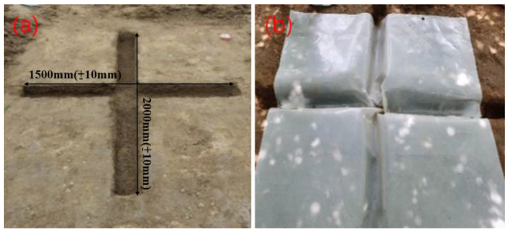
Cross-groove-shaped laying method. As shown in Figure 2a, the unidirectional recess is modified based on the recess-type slack preparation method by changing the unidirectional recess into a cross-groove-shaped bidirectional recess. In this case, the size of the recess must be determined according to the corresponding specifications [17,18,19]. When the geomembrane is subjected to tensile stress due to environmental changes, the geomembrane in the cross-shaped recess is lifted so that the geomembrane is not tight, even when subjected to tensile stress. Theoretically, when the geomembrane is subjected to tensile stress in any direction, the geomembrane hidden in the cross-shaped grooves will be pulled up. So, the cross-shaped groove can basically address tensile stresses in any direction of the geomembrane.
(2)
Cross-Z-shaped laying method. Based on the unidirectional Z-shaped technique, the geomembrane is folded in a direction perpendicular to the original Z shape to obtain a bidirectional Z shape, as shown in Figure 2b. The Z-shaped slackening reservation method is shown in Figure 2b.
(3)
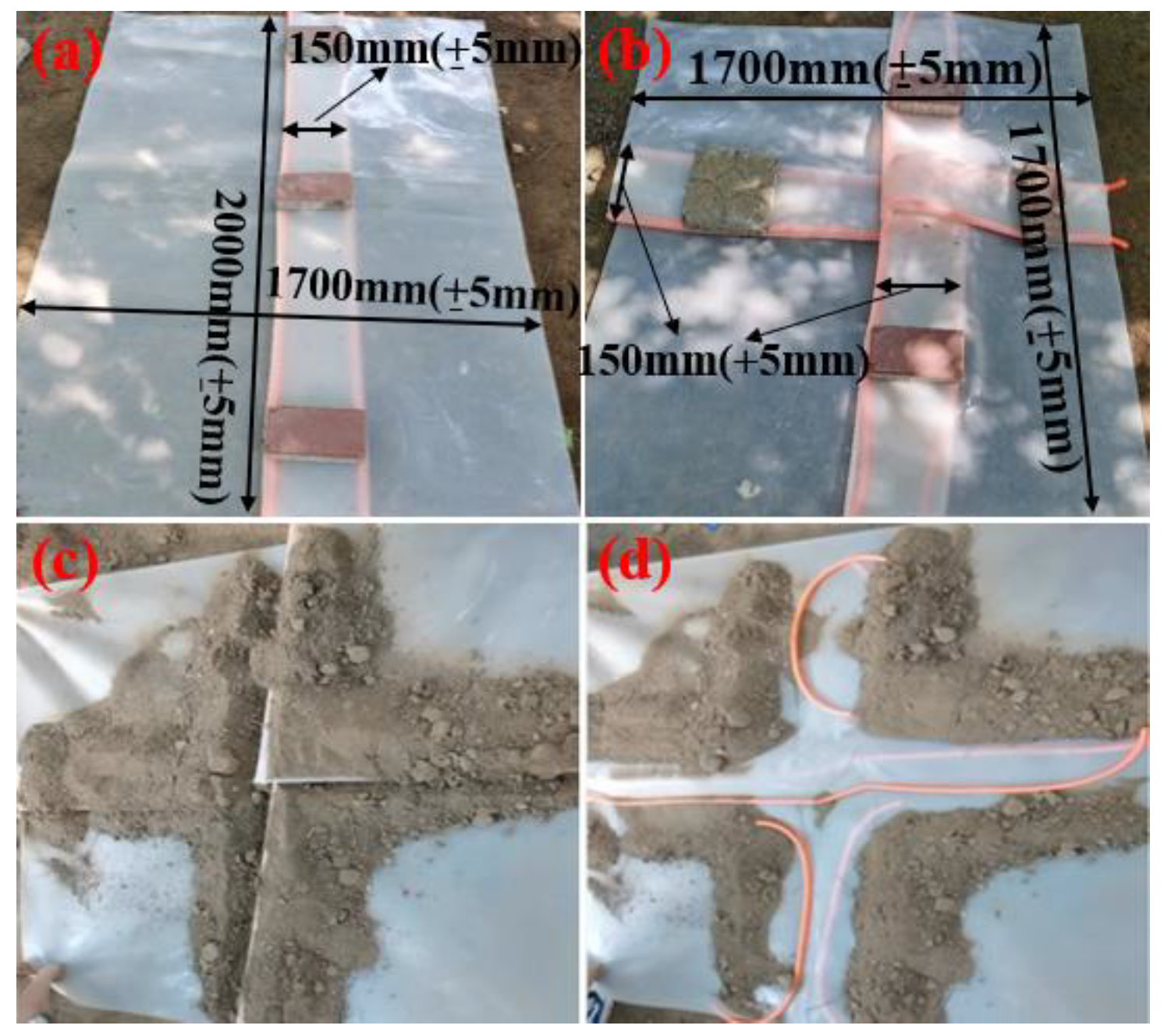
Combined Z- and groove-shaped laying method. By combining the unidirectional Z shape and unidirectional groove shape, a new bidirectional geomembrane slack reservation method can be obtained. As shown in Figure 2c, the unidirectional Z-folded geomembrane is laid on a foundation with a unidirectional groove. In this case, the zigzag folded strip is geometrically perpendicular to the recess.

3. Analysis and Comparison of Different Methods

To clarify the key issues and their feasible solutions in the practical application of the bidirectional reservation method for geomembranes proposed in this paper, field validation tests were conducted. HDPE geomembranes that have been used in a reservoir pan impermeability project from a plain reservoir in Xinjiang were used in this study. According to the manufacturer, the physical properties of the HDPE geomembranes are shown in Table 1.

3.1. Cross-Notch-Type Centralized Laying Relaxation Amount Method Analysis

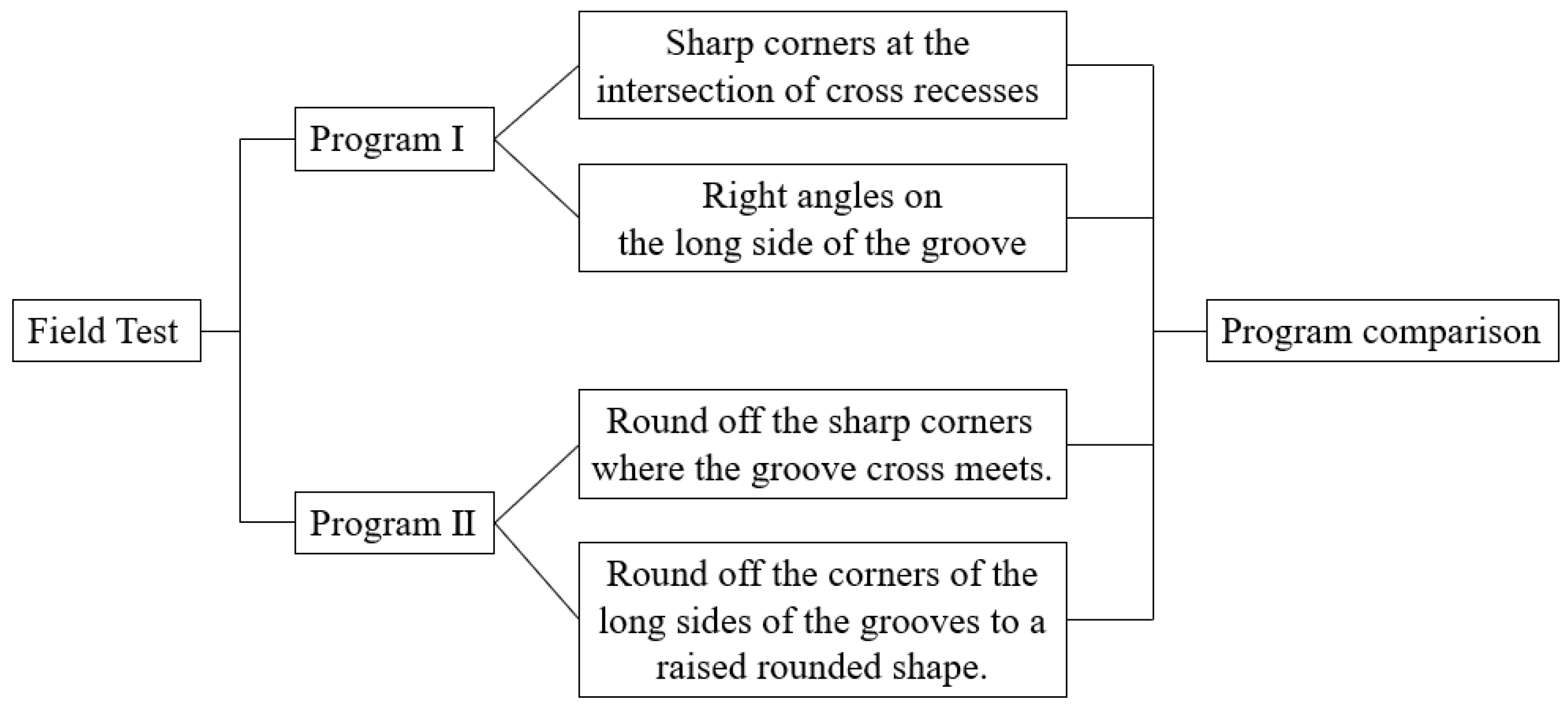
3.1.1. Program Design

The bidirectional cross-groove-shaped reservation method involves excavating a cross-groove-shaped recess with a cross-shaped bidirectional intersection. To explore the reliability of the cross-recess-type bidirectional reservation method, site earth excavation and geomembrane laying tests were conducted. First, a suitable site is selected, and the test site surface is cleaned with an SD160 bulldozer to remove roots, weeds, debris, rocks, and humus from the surface layer. Second, the cross-groove shape is excavated. The basic dimensions of the preliminary excavated test area are as follows: the length of the groove in the vertical direction is 2 m, the length of the groove in the horizontal direction is 1.5 m, the width of the groove is 0.15 m, the depth of the groove is 0.15 m, and the cross-groove is surrounded by right-angle edges. Finally, the geomembrane is laid on the cross-groove using the bidirectional reservation method.
To solve the problem of the bidirectional cross-shaped reservation method producing severe creasing at the intersection, setting wiping corners at the edges is proposed. The specific test program is shown in Figure 3 below.

3.1.2. Right Angle Program

The corners of the cross-recesses in Program I were not treated, and the cross-recesses were surrounded by right-angle edges. The results of the laying test are shown in Figure 4. From Figure 4a,b, with the original grooves, although the left and right banks of each do not show obvious folds, the membrane produces large folds at the cross-intersection, affecting the safety of geomembrane impermeability.
A theoretical analysis was conducted on the causes of folds to eliminate those that occur at the cross-intersection of cross-groove geomembranes. Folds occur when the geomembrane transforms from flat into recessed into the groove. After this transformation, the excess membrane does not fit the surface of the groove, and it is reflected in the form of folds. Figure 5 below shows a model of the principle of excess geomembrane generation when geomembranes are laid in a bidirectional manner in a cross-rectangular recess. As shown in Figure 5, when the geomembrane in a flat state plunges into the recess, the geomembrane in four directions (south, east, north, and west) moves toward the cross-intersection. According to the geometric relationship, the shaded part in Figure 5 represents the excess membrane area generated during the bidirectional laying of the cross-groove geomembrane. Therefore, the excess membrane area generated during the bidirectional laying of the cross-groove geomembrane is calculated as follows, where S m is the area of the geomembrane forming the fold, h is the depth of the groove, and b is the width of the groove.
S m = 2 h + b 2 b 2 = 4 h ( h + b )

3.1.3. Plastering Program

From the above formula, it is clear that the number of geomembrane folds generated by untreated cross-recesses is significantly increased. The best method for eliminating folds while bidirectionally reserving the geomembrane is to move the excess geomembrane generated by the recesses from all sides toward the center. Since the excess geomembrane is generated by the presence of cross-intersections, a cross-groove intersection grinding solution is adopted to find the optimum cross-intersection over-angle to substantially eliminate the excess membrane area.
A field corner-smoothing program (Program II) is conducted to allow the geomembrane to transition smoothly into the cross-recesses without creasing. According to the field test, the upper corners of the sidewalls of the cross-recesses and the four sharp corners at the intersection of the cross-recesses can be smoothed. Among these parts, the upper corners of the sidewalls are the easiest to handle, as they can be polished into rounded shapes. A difficulty of this study is the handling of the four sharp corners at the cross-intersection of the recess.
After preliminary field tests, we find that grinding the sharp corners of the recesses at the cross-intersections to create a spherical structure, as shown in Figure 6a, can effectively consume the extra concentrated geomembrane at the cross-intersections in the bidirectional recess reservation. As shown in Figure 6b, the number of geomembrane folds at the cross-intersections is significantly reduced. However, the geomembrane folds generated under this solution are still large and cannot guarantee the preservation of the geomembrane impermeability characteristic.
After wiping the corners and laying the geomembranes several times to evaluate the effects of corner wiping, we found a spherical shape that could remove the concentrated geomembrane folds in the center of the groove cross. The results of the treatment are shown in Figure 6c,d. After measurement, the dimensions of the structure are as shown in Figure 6e,f, with a slope arc of 35° and a total length of 1.3 m for the diagonal two-arc slope connection, which is approximately 6 times longer than the length of the rectangular diagonal at the cross-intersection before treatment.
Cross-recesses can meet the requirements of bidirectional geomembrane slack retention. After detailed corner wiping, the four sharp corners at the intersection of cross-recesses were treated as spherical footings with an arc of 35°, and the diagonal length of the footings was expanded 6 times. The cross-recesses can allow the geomembrane slack to enter the recesses approximately without folds, ensuring the safe laying of geomembranes. Therefore, we believe that the optimal wiping angle for the cross-groove-shaped technique is 35°. However, this method of reservation requires two cross-shaped grooves to be excavated at regular intervals, increasing civil construction costs to a certain extent. Moreover, to lay the geomembrane into cross-recesses without excess folding, the cross-intersections of the recesses need to be sharpened, increasing the difficulty of construction.

3.2. “Z” Cross-Type Two-Way Centralized Lay-Up Relaxation Amount Method Analysis

The geomembrane is cross-folded in both directions, as shown in Figure 7. The long red tube under the membrane is a substitute for the neoprene rod, which is softer than the neoprene rod and makes it easier to realize the second Z fold. For the convenience of description, the two directions of folding are the X and Y directions, as shown in Figure 7a,b. The specific folding steps are as follows: (1) take the line where the Y-axis is located as the crease for the first zigzag fold and (2) take the line where the X-axis is located as the crease for the second zigzag fold. The final formation of the Z crossover geomembrane, as shown in Figure 7b, is a bidirectional reservation method.
The key to the bidirectional Z-cross-shaped geomembrane reservation method is if and how easily the folded part can be separated when subjected to external stresses. To explore the effectiveness of the geomembrane bidirectional cross-Z-shaped reservation method, a bidirectional tensile test is conducted, as shown in Figure 7c,d.
The test results show that the geomembrane can be separated well after cross-Z-shaped folding and that the whole geomembrane is relatively flat after being separated. To carry out the test effectively, the neoprene rubber gang that prevents the geomembrane from breaking is replaced with a PE hose to achieve a 180-bend effect when the geomembrane is folded for a second time. However, the neoprene rods used in practice do not achieve a 180-degree bend. In addition, once the geomembrane slack is separated, the geomembrane cannot be restored to its original state once the force is removed. Moreover, the slackened part of the geomembrane may form folds under pressure, thus shortening the service life of the geomembrane.

3.3. Analysis of “Z” and Groove Combination-Type Two-Way Pre-Set Concentration Laying Slack Amount Method

Both the cross-Z-shaped and cross-groove bidirectional reservation methods have shortcomings, among which the cross-Z-shaped technique cannot achieve 180-degree bending when folding the second time. Once the slack in the geomembrane is separated when force is applied, the geomembrane cannot be restored to its original shape when the force is removed. The cross-groove method requires a large amount of excavation, increasing the civil construction cost to a certain extent. Due to the disadvantages of the cross-groove and bidirectional cross-Z-shaped reservation methods, the two methods were integrated, and a bidirectional and concentrated combined Z- and groove-shaped laying reservation method is proposed.
To explore the effects of the bidirectional reservation of the combined Z- and groove-shaped concentrated laying reservation method, an outdoor laying test is conducted, as shown in Figure 8. The test is conducted by excavating a U groove that is 2 m in length, 0.15 m in width, and 0.15 m in depth and by laying a piece of HDPE geomembrane that is 2 × 2 m in size and 0.8 mm in thickness in a unidirectional Z fold, as shown in Figure 8.
As shown in Figure 8, the bidirectional reservation method of combined Z- and groove-shaped geomembrane slack can avoid wrinkles in the cross-groove-shaped slack and neoprene rods that cannot complete 180-degree bending in the cross-Z-shaped slack. Moreover, since this bidirectional reservation method requires only one groove for excavation, the civil construction volume is reduced by half relative to the cross-groove shape.

3.4. Comparison of Different Methods

3.4.1. Comparison of Bidirectional and Unidirectional Slack Reservation Methods

In terms of cost: there is no doubt that the proposed bidirectional reservation of geomembrane slack will increase the construction cost to a certain extent.
Effectiveness perspective: compared with the existing unidirectional reservation of geomembrane relaxation, the bidirectional reservation of geomembrane relaxation proposed in this paper is more effective and can better protect the safe operation of the geomembrane. Because of one-way reserved geomembrane relaxation, at this time the geomembrane relaxation can only cope with a certain direction of tensile stress. This is a big gamble because in practice no one knows which direction of tensile stress the geomembrane will be subjected to as a result of changes in environmental factors.
Ease of implementation: compared to the existing unidirectional geomembrane relaxation, the bidirectional geomembrane relaxation proposed in this paper will make the construction procedure somewhat more difficult, but not by much.
It is more reasonable to carry out bidirectional geomembrane relaxation in terms of the safety performance of the project. And the safety of the project must be the first consideration.

3.4.2. Comparison between Different Bidirectional Relaxation Allowance Methods

As shown in Figure 6, when the geomembrane is laid with the bidirectional concentrated cross-groove reservation method, the geomembrane produces relatively small folds when the four corners of the cross-notch intersection are polished to 35°, which does not affect the safety of geomembrane impermeability. Moreover, when the geomembrane is subjected to tensile stress due to changes in environmental factors, the amount of geomembrane reservation hidden in the grooves is lifted to offset the tensile stress. When the tensile stress disappears, the lifted part of the geomembrane is pressed into the grooves under overlying pressure, forming a cycle of sustainable use. However, this method requires a large amount of excavation, increasing construction costs to a certain extent. In contrast, the bidirectional cross-Z-shaped reservation method shown in Figure 6 reduces civil construction work by laying the folded geomembrane directly on the foundation surface without the need for excavation. However, as seen in Figure 7, the Z-shaped intersection is a 6-layer geomembrane that is folded into a cross shape, and geomembrane folds are more serious and should not be solved. Moreover, this bidirectional cross-folding method requires a 180-degree bend of the first folded layer when folding for the second time. However, the existing neoprene rods on the market cannot meet the 180-degree bend requirement. Once the geomembrane is subjected to tensile stress and the folded layer is separated, the folded layer cannot be restored to its original state when the tensile stress disappears, and it cannot address the subsequent reappearance of the tensile stress. Relative to the first two cases, the geomembrane shown in Figure 8 can meet the requirement of bidirectional reservation of geomembrane slack, as the number of folds produced becomes almost negligible by laying the geomembrane in a concentrated manner with the combined Z- and groove-shaped method. However, once the cross-Z-shaped folded part is separated, it cannot be restored to its original state after the tensile stress disappears, and the bidirectional slack reservation becomes unidirectional. A comparative analysis of different geomembrane slack reservation methods in both directions is summarized as follows. This technical note does not quantitatively analyze the specific effects of different relaxation amount reservation methods for geomembranes. This technical note only presents a methodology for bidirectional retention of geomembrane relaxation and verifies the feasibility of the proposed new construction method for geomembranes through outdoor testing.

Advantages

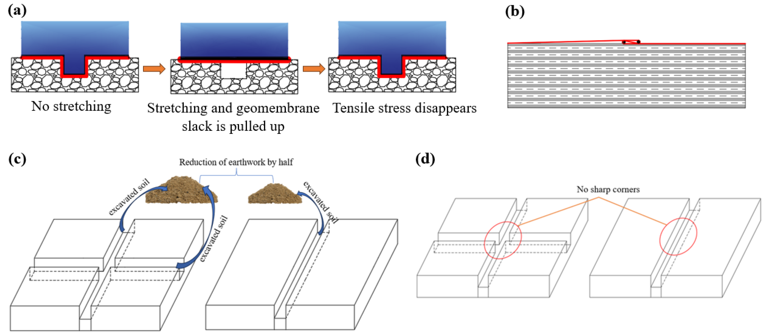
  • Bidirectional cross-groove-shaped method: as shown in Figure 9a, the groove-shaped slack can be restored to its original state after the stress disappears and used continuously.
  • Bidirectional cross-Z-shaped method: as shown in Figure 9b, the Z-shaped slack is laid directly on the ground. No trenching is needed, saving civil construction work.
  • Combined groove- and Z-shaped method: j as shown in Figure 9c, compared with the bidirectional cross-groove-shaped method that requires two grooves to be excavated, the combined groove- and Z-shaped method requires only one groove to be excavated, which saves civil engineering work. k As shown in Figure 9d, the method of combining groove- and Z-shaped methods has only one notch, there is no sharp corner at the intersection of the two notches. This eliminates the need for edge angle detailing.

Disadvantages

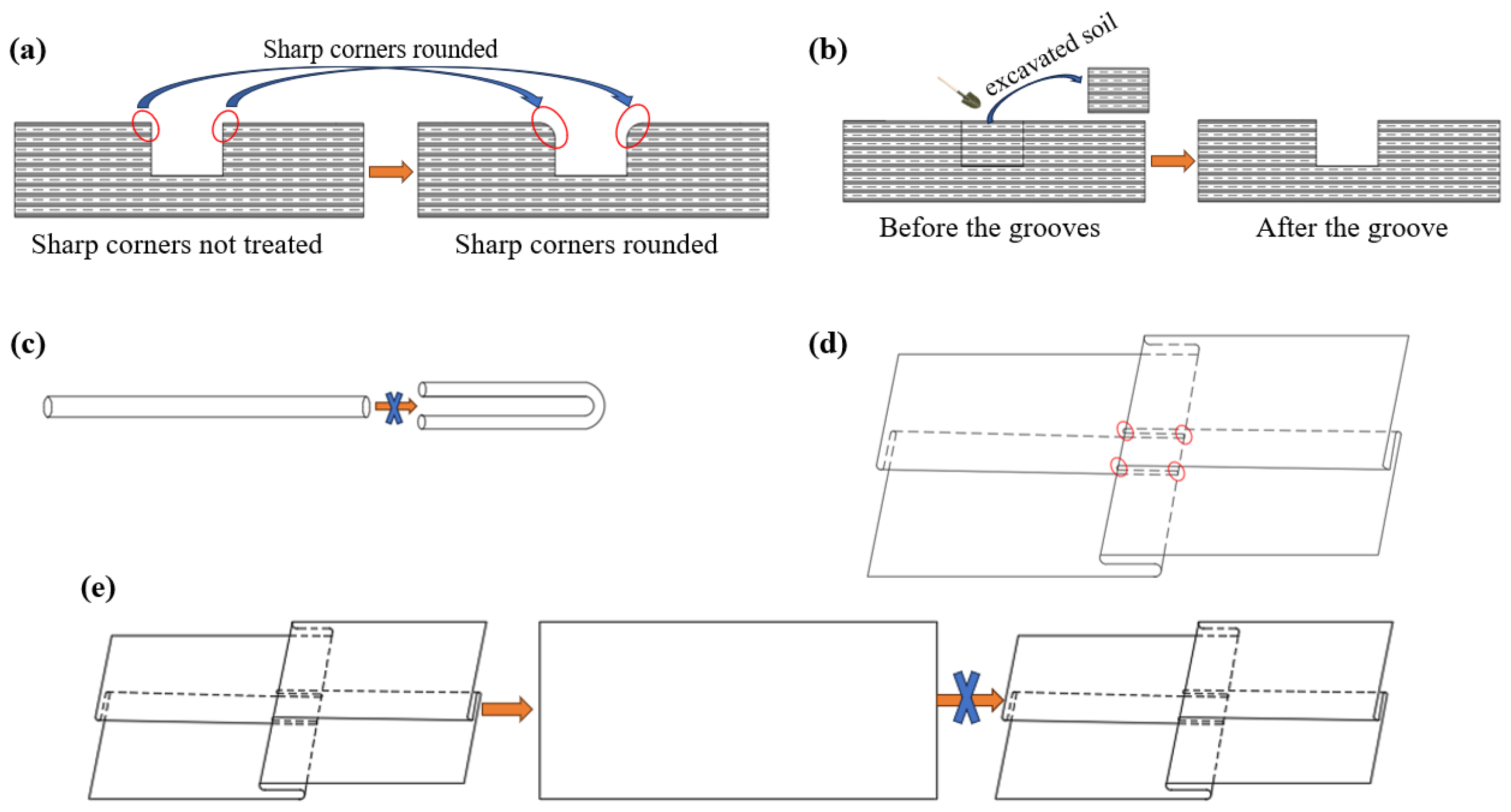
  • Bidirectional cross-groove-shaped method: j as shown in Figure 10a, the edge angles of the notches cause the geomembrane to crease, which is undesirable. However, the edge angle of the groove is cumbersome to deal with. k As shown in Figure 10b, the presence of grooves requires a large amount of earth excavation, increasing construction costs. l The difficulty of construction is increased.
  • Bidirectional cross-Z-shaped method: j as shown in Figure 10c, neoprene rods cannot be folded 180°. k As shown in Figure 10d, it is prone to geomembrane damage at the cross-intersections when folded. l As shown in Figure 10e, a bidirectional Z-shaped slack laid flat on a flat surface may not be restored to its original mount once it has been pulled apart. It cannot be continuously recycled.
  • Combined groove- and Z-shaped method: j the cross-Z-shaped method can be used only once. k After one use, it is easily broken under pressure with creases.
Comprehensively comparing the different geomembrane slack bidirectional reservation methods in the above, we find that only from the safety point of view should the bidirectional groove-type reservation be prioritized when laying the geomembrane slack.

4. Discussion

Geomembranes require a certain amount of slack when laid, but the existing geomembrane slack reservation method is a unidirectional technique that only addresses the impacts of stresses from a certain direction on the geomembrane. In practice, the tensile stresses generated by ambient temperature changes and uneven foundation settlement are directionally uncertain. Thus, the existing geomembrane slack reservation method is a poor solution to the problem of tensile stresses from different directions on the geomembrane. Therefore, in this paper, based on the existing geomembrane slack reservation methods, we have explored four techniques that can prevent tensile damage to geomembranes by tensile stresses from any direction. In terms of long-term effects, the proposed method in this paper (bidirectional reservation of geomembrane relaxation) can offset the tensile stresses on the geomembrane due to changes in environmental factors, thus achieving the protection of the geomembrane and enhancing the durability of the geomembrane.
The test described in this paper explores several feasible methods of bidirectional geomembrane slack retention, such as the magnitudes of tensile stresses that different techniques can manage under the same load, the magnitude of external tension required for the same reserved geomembrane slack to be eliminated under different loads, and the amount of external tension required to address different external tensions to protect the geomembrane. The problem of the size of the required slack allowance for geomembranes has not been effectively solved. Therefore, further research on this topic is needed to compile a set of relationships concerning different loads, geomembrane slack reservation methods, reserved geomembrane slack sizes, and external tensions that the geomembrane can manage when the reserved slack is completely consumed to provide a reference for the laying of geomembranes in actual engineering construction projects.

5. Conclusions

In this paper, the existing geomembrane relaxation unidirectional reservation method is modified on the basis of the proposed bidirectional reservation method of geomembrane relaxation. The feasibility of the proposed new geomembrane construction method was verified by a geomembrane-laying test, and the specific conclusions are as follows.
(1)
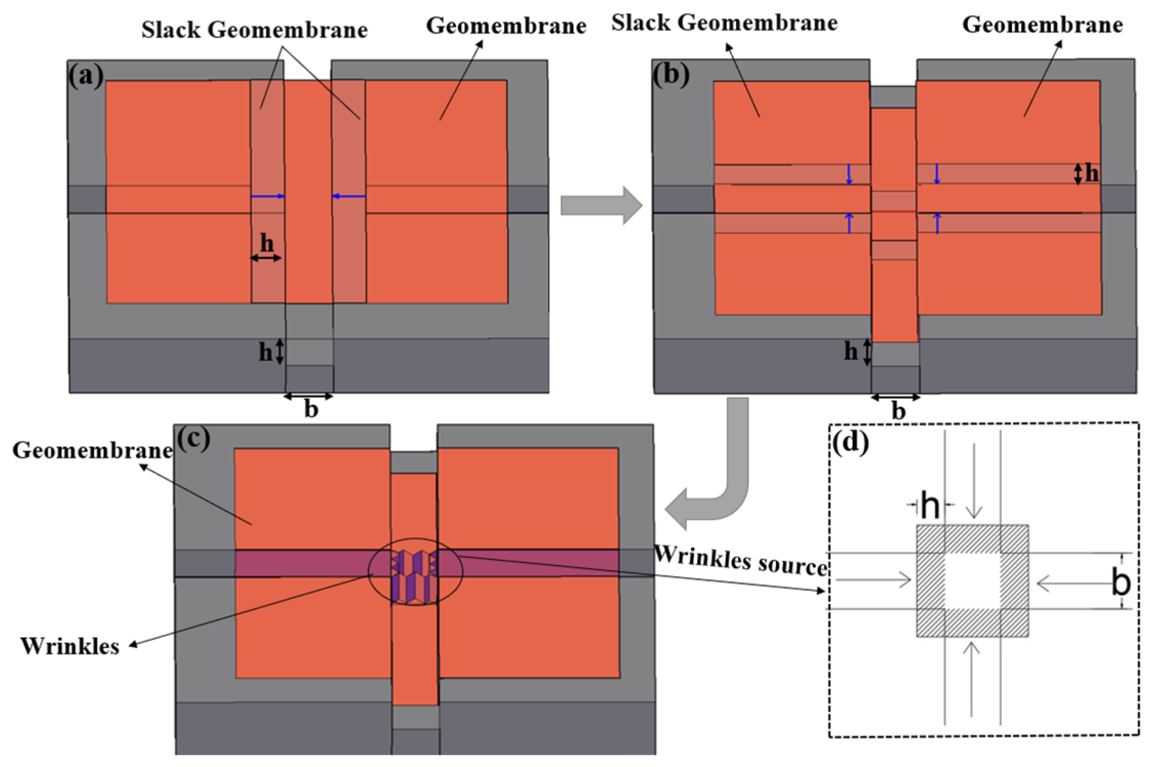
Geomembrane folds are concentrated at the cross-intersection of the groove in the bidirectional reservation method, and the space at the cross-intersection can be increased by grinding the four corners to consume excess geomembrane. The corners of the cross-intersection should be polished to a 35° angle of inclination, and the diagonal arc length of the cross-intersection should be 1/2 of the total length of the groove.
(2)
The cross-Z-shaped bidirectional folding and reservation method produces a negligible number of folds due to the excessive neoprene rods. However, the required neoprene rods cannot achieve 180-degree folding, which is the largest obstacle to the effective implementation of this method. Once the reserved portion is separated, the folded layer cannot be restored to its original state when the stress disappears, and there is no slack to protect the geomembrane when it is subjected to tensile stress.
(3)
The bidirectional reservation method combining the Z- and groove-shaped techniques produces a negligible number of folds, and it does not require a 180° folding layer of neoprene rods. Only a unidirectional U-shaped groove is provided, which greatly reduces the earthwork excavation cost. The disadvantage of this method is that once the unidirectional Z-shaped folded layer is separated, it cannot be restored to its original form and instead becomes a unidirectional reservation mode after one use.
(4)
For safety reasons only, bidirectional notch-type allowances should be prioritized for the amount of slack in geomembrane placement.

Author Contributions

Conceptualization, W.W. and X.X.; methodology, W.W.; software, Z.L.; validation, W.L., W.W. and X.X.; formal analysis, R.H.; investigation, Z.L.; resources, W.L.; data curation, Z.L.; writing—original draft preparation, W.W.; writing—review and editing, W.W.; visualization, X.X.; supervision, W.W.; project administration, W.L.; funding acquisition, W.L. All authors have read and agreed to the published version of the manuscript.

Funding

This work was financially supported by the Natural Science Foundation of Shandong Province, China (ZR2019MEE106).

Institutional Review Board Statement

Not applicable.

Informed Consent Statement

Not applicable.

Data Availability Statement

Data are contained within the article.

Acknowledgments

The authors would like to thank the reviewers for their critical reviews and suggestions for improving the quality of this manuscript.

Conflicts of Interest

The authors declare that they have no known competing financial interests or personal relationships that could have appeared to influence the work reported in this paper. Ruichen Han is an employee of Shandong Survey and Design Institute of Water Conservancy Co., Ltd., who provided methodology, situation analysis, and technical support for the work.

References

  1. Sharma, H.D.; Reddy, K.R. Geoenvironmental Engineering: Site Remediation, Waste Containment and Emerging Waste Management Technologies; John Wiley & Sons: Hoboken, NJ, USA, 2004. [Google Scholar]
  2. Li, W.L.; Li, Z.Q.; Su, X.C.; Xu, F.; Wei, R.C.; Zhang, B.F. Field Experimental of Eliminating Geomembrane Air Expansion by Vacuumizing for Plain Reservoir. Geotech. Test. J. 2019, 42, 221–231. [Google Scholar] [CrossRef]
  3. Yu, H.R.; Wei, R.C.; Li, C.; Li, W.L. Experimental Study on Air Expansion Deformation of Composite Geomembrane under Ring-Restrained Condition. Geotech. Test. J. 2020, 43, 1191–1200. [Google Scholar] [CrossRef]
  4. Lavoie, F.L.; Valentin, C.A.; Kobelnik, M.; Lins da Silva, J.; Lopes, M.D.L. HDPE Geomembranes for Environmental Protection: Two Case Studies. Sustainability 2020, 12, 8682. [Google Scholar] [CrossRef]
  5. Schmachtenberg, E.; Schoeche, N. Advances in calculating thermally induced stresses in nonlinear viscoelastic materials. Polym. Eng. Sci. 1999, 39, 767–777. [Google Scholar] [CrossRef]
  6. Imaizumi, S.; Kawamata, K.; Tsuboi, M. Study on thermal stress within the geomembrane liner induced by temperature decrease. In Proceedings of the 7th International Landfill Symposium, Cagliari, Italy, 4–8 October 1999; pp. 115–122. [Google Scholar]
  7. Krishnaswamy, R.K. Analysis of ductile and brittle failures from creep rupture testing of high-density polyethylene (HDPE) pipes. Polymer 2005, 46, 11664–11672. [Google Scholar] [CrossRef]
  8. Merry, S.M.; Bray, J.D.; Yoshitomi, S. Axisymmetric temperature- and stress-dependent creep response of ‘new’ and ‘old’ HDPE geomembranes. Geosynth. Int. 2005, 12, 156–161. [Google Scholar] [CrossRef]
  9. Zhang, X.; Ma, Z.; Wu, Y.; Liu, J. Response of Mechanical Properties of Polyvinyl Chloride Geomembrane to Ambient Temperature in Axial Tension. Appl. Sci. 2021, 11, 10864. [Google Scholar] [CrossRef]
  10. Wu, H.M.; Shu, Y.M.; Cao, M.J. Development and application of multi-functional biaxial tensile testing machine for geosynthetics. Chin. J. Geotech. Eng. 2014, 36, 170–175. [Google Scholar]
  11. Frost, J.D.; Karademir, T. Shear-induced changes in smooth geomembrane surface topography at different ambient temperatures. Geosynth. Int. 2015, 23, 113–128. [Google Scholar] [CrossRef]
  12. Giroud, J.P.; Soderman, K.L. Comparison of Geomembranes Subjected to Differential Settlement. Geosynth. Int. 1995, 2, 953–969. [Google Scholar] [CrossRef]
  13. Wu, H.; Feng, L.; Teng, Z.; Shu, Y. Model Test on Mechanical and Deformation Property of a Geomembrane Surface Barrier for a High Rockfill Dam. Appl. Sci. 2021, 11, 11505. [Google Scholar] [CrossRef]
  14. Xu, S.F.; Yang, Y.A.N.G.; Hong, B. Evaluation of temperature stress and stress relaxation properties of HDPE sheet. J. Southeast Univ. 2006, 36, 820–824. [Google Scholar]
  15. Fang, C.; Xu, S.; Yang, Y. Study on temperature stress of HDPE geomembrane. China Build. Waterproofing 2010, 6, 10–12. [Google Scholar]
  16. Gao, D.; Zhu, B.; Chen, Y.M. Mechanism and analytic model of wrinkled geomembranes around circular structures subjected to differential settlement. Chin. J. Geotech. Eng. 2008, 30, 1126–1132. [Google Scholar]
  17. GB50290-98; Brief Introduction of Technical Specification for Application of Synthetic Materials to Soil Engineering GB. China Plan Press: Beijing, China, 1998.
  18. DL/T 5743-2016; Code for Construction of Geosynthetics for Hydropower and Water Conservancy Projects. Code of China: Beijing, China, 2016.
  19. SL/T225-98; Standard for Applications of Geosynthetics in Hydraulic and Hydro-Power Engineering. China Water Power Press: Beijing, China, 1998.
  20. Zheng, X. Talk about evaporation pond laying geomembrane construction requirements. Shanxi Water Resour. 2016, 3, 79–80. [Google Scholar]
  21. Zhao, E.-H. Design Difficulties and Solutions for Water Supply Project in Tangshan Leting New District. Hebei Water Resour. 2017, 1, 41. [Google Scholar]
  22. Available online: https://www.docin.com/p-2699715481.html (accessed on 1 May 2023).
  23. Soong, T.Y.; Koerner, R.M. Behavior of waves in high density polyethylene geomembranes: A laboratory study. Geotext. Geomembr. 1999, 17, 81–104. [Google Scholar] [CrossRef]
  24. Chappel, M.J.; Rowe, R.K.; Brachman, R.W.I.; Take, W.A. A comparison of geomembrane wrinkles for nine field cases. Geosynth. Int. 2012, 19, 453–469. [Google Scholar] [CrossRef]
  25. Take, W.A.; Watson, E.; Brachman, R.W.I.; Rowe, R.K. Thermal Expansion and Contraction of Geomembrane Liners Subjected to Solar Exposure and Backfilling. J. Geotech. Geoenvironmental Eng. 2012, 138, 1387–1397. [Google Scholar] [CrossRef]
  26. Yang, P.; Xue, S.B.; Song, L.; Zhu, X.W. Numerical simulation of geomembrane wrinkle formation. Geotext. Geomembr. 2017, 45, 697–701. [Google Scholar] [CrossRef]
  27. Popova, M.B.; Iliev, V.D. Analytical model for anisotropic geomembrane composites. Geotext. Geomembr. 1990, 9, 269–280. [Google Scholar] [CrossRef]
  28. Duvall, D.E. Creep and Stress Rupture Testing of a Polyethylene Geomembrane Under Equal Biaxial Tensile Stress. In Proceedings of the Geosynthetics, Vancouver, BC, Canada, 30 March–1 April 1993; Volume 12, pp. 285–295.
  29. Lecompte, D.; Smits, A.; Sol, H.; Vantomme, J.; Van Hemelrijck, D. Mixed numerical–experimental technique for orthotropic parameter identification using biaxial tensile tests on cruciform specimens. Int. J. Solids Struct. 2007, 44, 1643–1656. [Google Scholar] [CrossRef]
  30. Yu, Y.; Rowe, R.K. Development of geomembrane strains in waste containment facility liners with waste settlement. Geotext. Geomembr. 2018, 46, 226–242. [Google Scholar] [CrossRef]
  31. Yuan, H.; Bai, X.; Zhao, H.; Wang, J. Experimental Study on the Influence of Aging on Mechanical Properties of Geogrids and Bearing Capacity of Reinforced Sand Cushion. Adv. Civ. Eng. 2020, 2020, 8839919.1–8839919.13. [Google Scholar] [CrossRef]
  32. ASTM D5199-12; Standard Test Method for Measuring the Nominal Thickness of Geosynthetics. ASTM International: West Conshohocken, PA, USA, 2019.
  33. ASTM D6693M-20; Standard Test Method for Determining Tensile Properties of Nonreinforced Polyethylene and Nonreinforced Flexible Polypropylene Geomembranes. ASTM International: West Conshohocken, PA, USA, 2020.
  34. ASTM D792-20; Standard Test Methods for Density and Specific Gravity (Relative Density) of Plastics by Displacement. ASTM International: West Conshohocken, PA, USA, 2020.
  35. ASTM D624; Standard Test Method for Tear Strength of Conventional Vulcanized Rubber and Thermoplastic Elastomers. ASTM International: West Conshohocken, PA, USA, 2020.
  36. ASTM D3192-09; Standard Test Methods for Carbon Black Evaluation in NR (Natural Rubber). ASTM International: West Conshohocken, PA, USA, 2019.
  37. ASTM D4833M-07; Standard Test Method for Index Puncture Resistance of Geomembranes and Related Products. ASTM International: West Conshohocken, PA, USA, 2020.
Figure 1. Diagram of existing slack allowance methods. (a) Wavy slack laying, (b) groove slack laying, (c) Z slack laying.
Applsci 13 12173 g001
Figure 2. Two-way reservation methods. (a) Cross-notch type, (b) double Z cross type, (c) Z and notch combination type.
Applsci 13 12173 g002
Figure 3. Preparation scheme of the bidirectional, concentrated, cross-groove-shaped slack-laying method for testing.
Applsci 13 12173 g003
Figure 4. Test results of Program I. (a) cross-groove, (b) laying test membrane.
Applsci 13 12173 g004
Figure 5. Calculation model of excess geomembrane in cross-notch bidirectional laying in Program I. (a) Geomembrane enters longitudinal groove, (b) geomembrane enters transverse groove, (c) bidirectional groove laying completed, (d) source of folds.
Applsci 13 12173 g005
Figure 6. Test results of Program II. (a) Preliminary determination of wiping method, (b) geomembrane-laying effect after preliminary wiping, (c) final cross-recess shape, (d) final geomembrane-laying effect, (e) slope foot curvature measurement, (f) diagonal two-arc slope connecting length measurement.
Applsci 13 12173 g006
Figure 7. Test results of “Z” cross-type two-way lay. (a) One-way fold, (b) two-way fold, (c) stretching process, (d) stretching completed figure.
Applsci 13 12173 g007
Figure 8. Test results of “Z” and groove combination type two-way laying. (a) One-way groove, (b) laying test film.
Applsci 13 12173 g008
Figure 9. Schematic diagram of the advantages of the three bidirectional reservation methods. (a) Work process for the geomembrane slack in the notch, (b) Z-shaped slack with no excavation required, (c) comparison of bidirectional notched earthmoving volumes, (d) comparison of combined groove- and Z-shaped method with bidirectional cross-groove-shaped corner disappearance.
Applsci 13 12173 g009
Figure 10. Schematic of the disadvantages of the three bidirectional reservation methods. (a) The process of grinding the sharp corners of the grooves, (b) the process of notch excavation, (c) neoprene rods cannot be folded 180°, (d) the sharp corner position of bidirectional Z-folded layer, (e) failure process of bidirectional cross-Z-shaped slack.
Applsci 13 12173 g010
Table 1. Characteristics of HDPE Geomembranes.
Material TypeCharacteristicsUnitValueStandard
HDPE GeomembraneThicknessmm0.8ASTM D5199-12 [32]
Fracture strengthN/mm21.2ASTM D6693M-20 [33]
Elongation at break%704ASTM D6693M-20 [33]
Densityg/cm30.940ASTM D792-20 [34]
Right angle tear strengthN/mm99.4ASTM D624 [35]
Carbon black content%2.2ASTM D3192-09 [36]
Puncture resistance strengthN257ASTM D4833M-07 [37]
Disclaimer/Publisher’s Note: The statements, opinions and data contained in all publications are solely those of the individual author(s) and contributor(s) and not of MDPI and/or the editor(s). MDPI and/or the editor(s) disclaim responsibility for any injury to people or property resulting from any ideas, methods, instructions or products referred to in the content.

