Performance Analysis of Polymer Additive Manufactured Gear Bearings

Abstract
:Featured Application
Abstract
1. Introduction
2. Materials and Methods
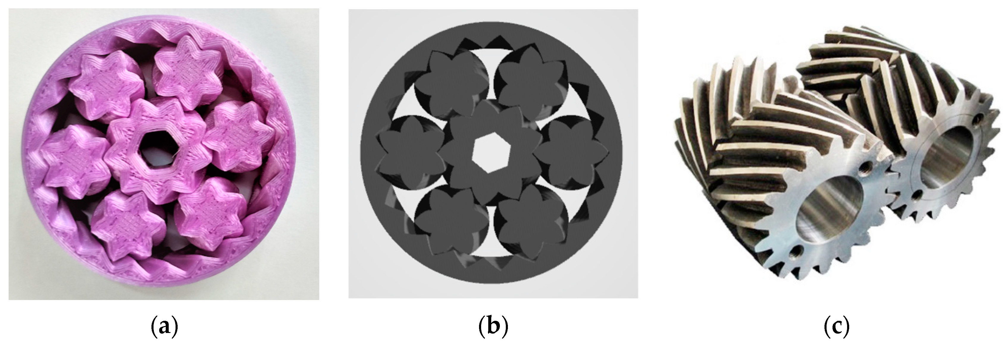
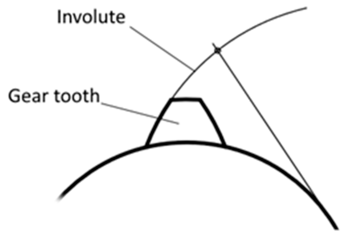
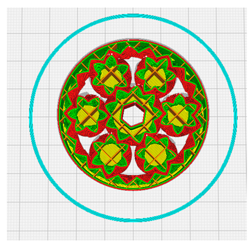
2.1. Gear Bearings: An Introduction—The Involute
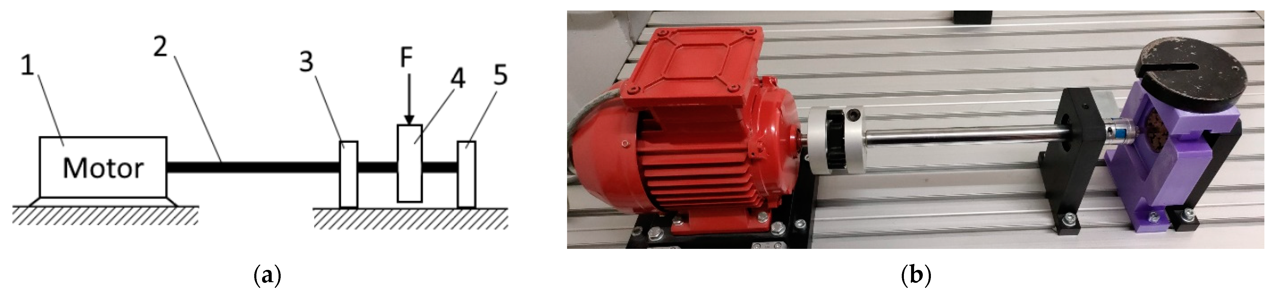
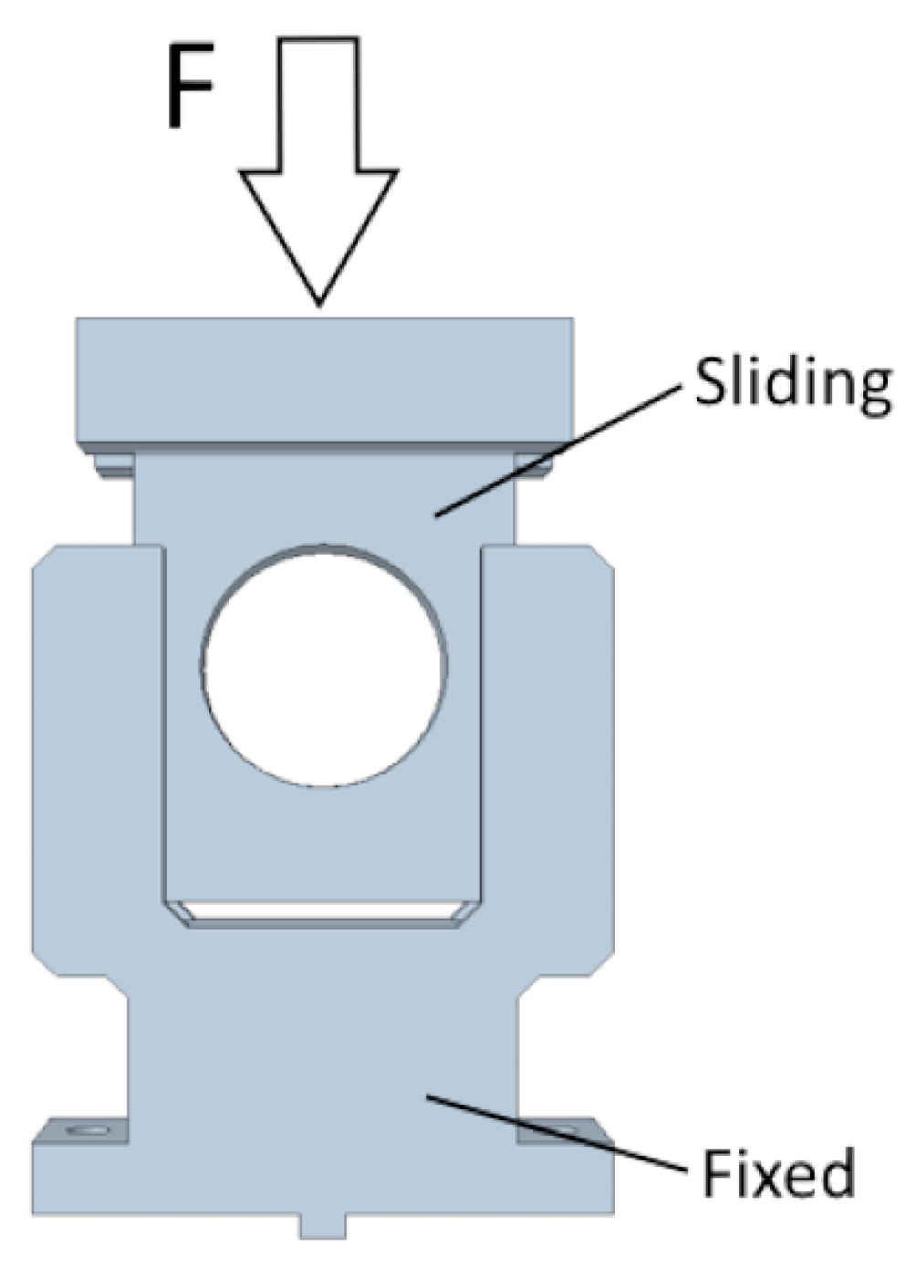
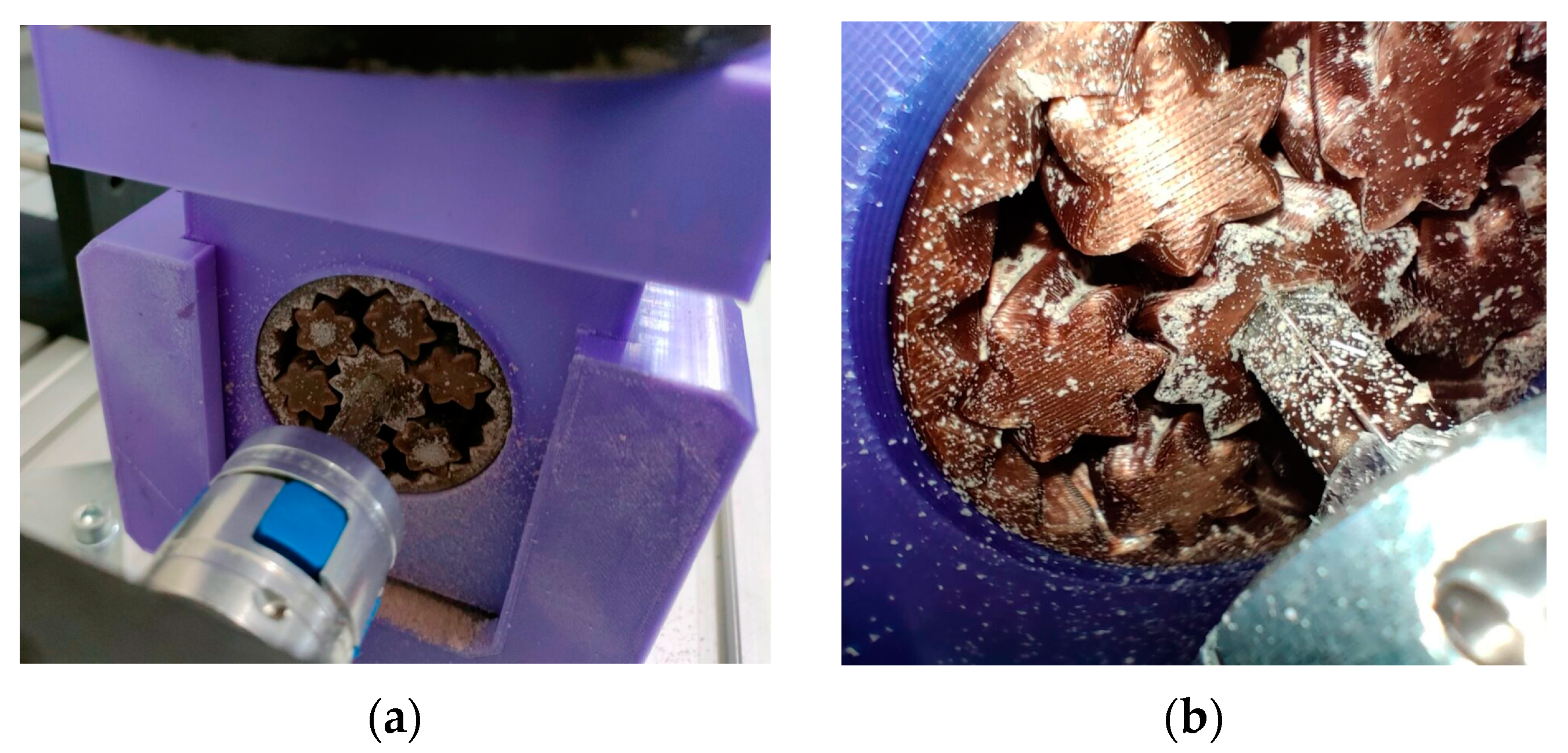
2.2. The Test Stand
2.3. Printer Settings
3. Results
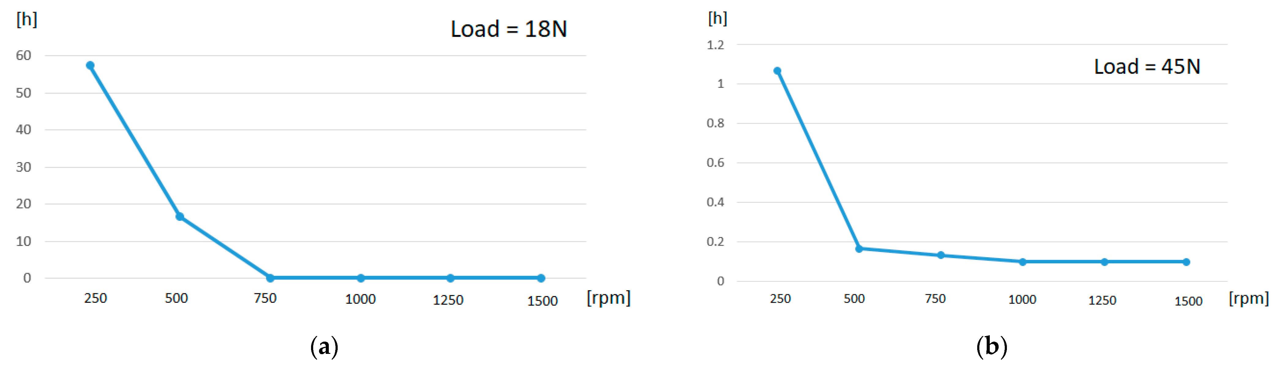
3.1. Lifetime
3.2. Temperature
3.3. Weight
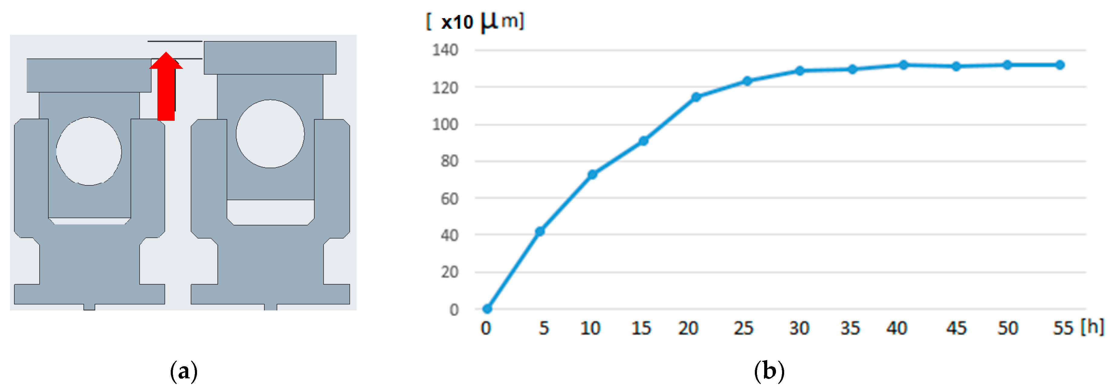
3.4. Radial Play
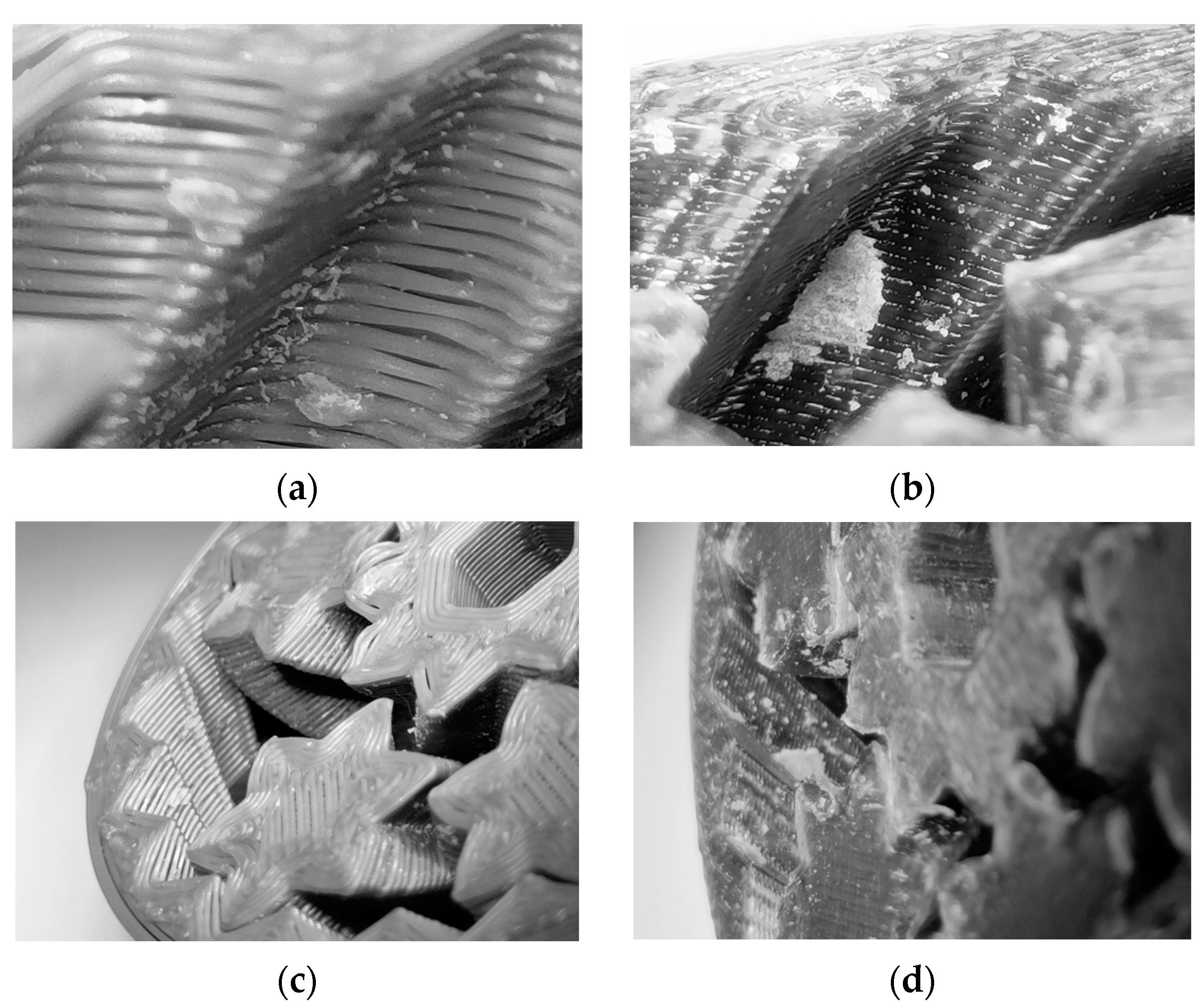
3.5. Failure Modes
- Gear jamming (J).
- Gear failure as a part (F).
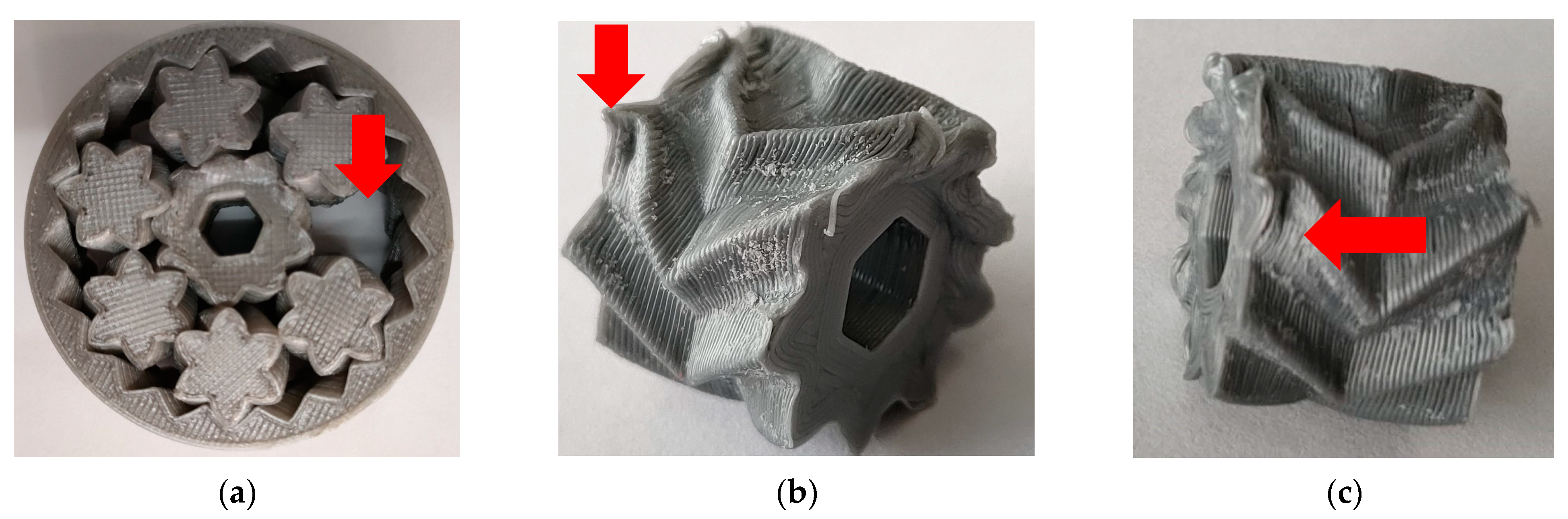
3.6. Material Abrasion and Buildup
3.7. Vibration
4. Conclusions
Author Contributions
Funding
Institutional Review Board Statement
Informed Consent Statement
Data Availability Statement
Conflicts of Interest
References
- NASA. Gear Bearings. Patent US6626792B2, 30 September 2003. [Google Scholar]
- NASA. Gear Bearing Drive. Patent US8016893B2, 13 September 2011. [Google Scholar]
- Walia, K.; Khan, A.; Breedon, P. Polymer-Based Additive Manufacturing: Process Optimisation for Low-Cost Industrial Robotics Manufacture. Polymers 2021, 13, 2809. [Google Scholar] [CrossRef]
- Mocan, M.; Mocan, B. Cardiac rehabilitation for older patients with cardiovascular pathology using robotic systems—A survey. Balneo Res. J. 2019, 10, 33–36. [Google Scholar] [CrossRef]
- Vranish, J.; Byrd, T. The High-Load Capacity of Gear Bearings Can Further Reduce Cost by Enabling the Use of Less Expensive, Lower Strength Materials. Available online: https://gearsolutions.com/features/the-future-of-gear-bearing-technology/ (accessed on 8 June 2023).
- Muminovic, A.J.; Pervan, N.; Delic Muratovic, E.; Mesic, E.; Braut, S. Failure analysis of nylon gears made by additive manufacturing. Eng. Fail. Anal. 2022, 137, 106272. [Google Scholar] [CrossRef]
- Maszybrocka, J.; Dworak, M.; Nowakowska, G.; Osak, P.; Łosiewicz, B. The Influence of the Gradient Infill of PLA Samples Produced with the FDM Technique on Their Mechanical Properties. Materials 2022, 15, 1304. [Google Scholar] [CrossRef] [PubMed]
- Hlebanja, G.; Hribersek, M.; Erjavec, M.; Kulovec, S. Durability Investigation of plastic gears. MATEC Web Conf. 2019, 287, 02003. [Google Scholar] [CrossRef]
- Singh, A.K.; Siddhartha; Singh, P.K. Polymer spur gears behaviors under different loading conditions: A review. Proc. Inst. Mech. Eng. Part J J. Eng. Tribol. 2018, 232, 210–228. [Google Scholar] [CrossRef]
- Prashant, K.S.; Siddhartha, A.K.S. An investigation on the thermal and wear behavior of polymer based spur gears. Tribol. Int. 2018, 118, 264–272. [Google Scholar] [CrossRef]
- Herzog, C.; Drummer, D. Test Rig for the In Situ Measurement of the Elastic Tooth Deflection of Plastic Gears. Polymers 2023, 15, 1732. [Google Scholar] [CrossRef] [PubMed]
- Tunalioglu, M.S.; Agca, B.V. Wear and Service Life of 3-D Printed Polymeric Gears. Polymers 2022, 14, 2064. [Google Scholar] [CrossRef] [PubMed]
- Lee, Y.J.; Lee, K.H.; Lee, C.H. Friction performance of 3D printed ball bearing: Feasibility study. Results Phys. 2018, 10, 721–726. [Google Scholar] [CrossRef]
- Rasmussen, E.; Rudolph, P.; Mamishev, A. An experimental study of 3D printed herringbone grooved journal bearings. In Proceedings of the ASME 2017 International Mechanical Engineering Congress and Exposition, Tampa, FL, USA, 3–9 November 2017. [Google Scholar]
- Igus—Wear-Resistant Polymers: 3D-Printed Components in the Tribology Test Lab. Available online: https://www.igus.com/info/3D-print-tribology-test (accessed on 12 October 2022).
- Rahul, R.; Abhijit, M. Tribological studies of 3D printed ABS and PLA plastic parts. Mater. Today Proc. 2021, 41, 856–862. [Google Scholar] [CrossRef]
- Bochnia, J.; Kozior, T.; Blasiak, M. The Mechanical Properties of Thin-Walled Specimens Printed from a Bronze-Filled PLA-Based Composite Filament Using Fused Deposition Modelling. Materials 2023, 16, 3241. [Google Scholar] [CrossRef] [PubMed]
- Involute. Available online: https://en.wikipedia.org/wiki/Involute (accessed on 23 January 2023).


| Quality | Layer height | 0.2 mm |
| Initial layer height | 0.2 mm | |
| Line width | 0.4 mm | |
| Walls | Wall thickness | 0.8 mm |
| Wall line count | 2 | |
| Top/bottom | Top/bottom thickness | 0.8 mm |
| Top/bottom layers | 4 | |
| Infill | Infill density | 15% |
| Infill pattern | Grid | |
| Infill overlap percent | 30% | |
| Infill overlap | 0.12 mm | |
| Material | Printing temp | 210 |
| Build plate temp | 60 | |
| Flow | 100% | |
| Build plate adhesion | Skirt |
| 250 rpm | 500 rpm | 750 rpm | 1000 rpm | 1250 rpm | 1500 rpm | |
|---|---|---|---|---|---|---|
| Test 1 (h) | 59 | 18 | 0.3 | 0.2 | 0.1 | 0.1 |
| Test 2 (h) | 58 | 16 | 0.1 | 0.1 | 0.1 | 0.1 |
| Test 3 (h) | 55 | 14 | 0.1 | 0.1 | 0.1 | 0.1 |
| Average (h) | 57.3 | 16 | 0.16 | 0.13 | 0.1 | 0.1 |
| 250 rpm | 500 rpm | 750 rpm | 1000 rpm | 1250 rpm | 1500 rpm | |
|---|---|---|---|---|---|---|
| Test 1 (h) | 1.1 | 0.2 | 0.2 | 0.1 | 0.1 | 0.1 |
| Test 2 (h) | 1.1 | 0.2 | 0.1 | 0.1 | 0.1 | 0.1 |
| Test 3 (h) | 1 | 0.1 | 0.1 | 0.1 | 0.1 | 0.1 |
| Average (h) | 1.06 | 0.16 | 0.13 | 0.1 | 0.1 | 0.1 |
| 18 N-250 rpm | 18 N-500 rpm | 18 N-750 rpm | 18 N-1000 rpm | 18 N-1250 rpm | 18 N-1500 rpm |
| J J J | J J F | J J J | J J J | J J J | J J J |
| 45N-250 rpm | 45 N-500 rpm | 45 N-750 rpm | 45 N-1000 rpm | 45 N-1250 rpm | 45 N-1500 rpm |
| J J J | J J J | J J F | J J J | J J J | J J J |
Disclaimer/Publisher’s Note: The statements, opinions and data contained in all publications are solely those of the individual author(s) and contributor(s) and not of MDPI and/or the editor(s). MDPI and/or the editor(s) disclaim responsibility for any injury to people or property resulting from any ideas, methods, instructions or products referred to in the content. |
© 2023 by the authors. Licensee MDPI, Basel, Switzerland. This article is an open access article distributed under the terms and conditions of the Creative Commons Attribution (CC BY) license (https://creativecommons.org/licenses/by/4.0/).
Share and Cite
Moldovan, C.; Sticlaru, C. Performance Analysis of Polymer Additive Manufactured Gear Bearings. Appl. Sci. 2023, 13, 12383. https://doi.org/10.3390/app132212383
Moldovan C, Sticlaru C. Performance Analysis of Polymer Additive Manufactured Gear Bearings. Applied Sciences. 2023; 13(22):12383. https://doi.org/10.3390/app132212383
Chicago/Turabian StyleMoldovan, Cristian, and Carmen Sticlaru. 2023. "Performance Analysis of Polymer Additive Manufactured Gear Bearings" Applied Sciences 13, no. 22: 12383. https://doi.org/10.3390/app132212383
APA StyleMoldovan, C., & Sticlaru, C. (2023). Performance Analysis of Polymer Additive Manufactured Gear Bearings. Applied Sciences, 13(22), 12383. https://doi.org/10.3390/app132212383