Article

Methodology for CubeSat Debris Collision Avoidance Based on Its Active ADCS System

by
Desiree González-Rodríguez
1,
Pedro Orgeira-Crespo
2,*,
Chantal Cappelletti
3 and
Fernando Aguado-Agelet
4
1
Doctoral Program in Aerospace Technology, Electromagnetic, Electronic, Computer and Mechanical Engineering, School of Telecommunications, University of Vigo, 36310 Vigo, Spain
2
Department of Mechanical Engineering, Heat Engines and Machines and Fluids, Aerospace Engineering School, University of Vigo, Campus Orense, 32004 Orense, Spain
3
Department of Mechanical, Materials and Manufacturing Engineering, University of Nottingham, Nottingham NG7 2RD, UK
4
Telecommunication Engineering School, University of Vigo, 36310 Vigo, Spain
*
Author to whom correspondence should be addressed.
Appl. Sci. 2023, 13(22), 12388; https://doi.org/10.3390/app132212388
Submission received: 5 October 2023 / Revised: 25 October 2023 / Accepted: 29 October 2023 / Published: 16 November 2023
(This article belongs to the Section Aerospace Science and Engineering)

Abstract

:
This research assesses the feasibility of a collision avoidance methodology for CubeSats lacking propulsion. The approach involves altering the satellite’s orientation to modify its cross-sectional area and, subsequently, the drag force. Examining altitudes within low Earth orbit (LEO) across 2U, 3U, and 6U CubeSat formats, maneuvers are considered two days before the Time to Closest Approach (TCA). Evaluation against the Conjunction Data Messages (CDMs) threshold miss distances reveals a minimum 7% and maximum 106% deviation in Vertical Distance Difference (VDD), and 68% to 1045% in Horizontal Distance Difference (HDD) concerning the notification threshold. These findings strongly endorse the practicality of the proposed collision avoidance methodology, utilizing CubeSat Attitude Determination and Control Systems (ADCS). Ongoing research focuses on assessing ADCS maneuver execution rates and implementation times, advancing our understanding and applicability of this innovative CubeSat collision avoidance approach.

1. Introduction

The number of functional satellites in low Earth orbit (LEO) is increasing rapidly, primarily due to the growth in commercial activities. The deployment of broadband mega-constellations is expected to double or even triple the number of operational satellites in the next five years.
The U.S. Joint Space Operations Center (JSpOC) is responsible for conducting conjunction assessments for all operational spacecrafts in relation to objects in the SSN catalogue. The results of these assessments are provided to the operators or owners of the vehicles involved in each conjunction. Based on this data, the International Space Station (ISS) has carried out 30 collision avoidance maneuvers since 1999, with three of them occurring in 2020 [1].
The International Space Station (ISS) recently executed the last collision maneuver on 24 August 2023, to avoid a potential collision with space debris. In response to the approaching debris, the Zvezda service module, a Russian component of the station, activated its engines for roughly 21.5 s. This action caused the ISS to shift its orbit downward by approximately 1640 feet (500 m), diverting it from the projected path of a fragment of orbital debris. Fortunately, this adjustment did not disrupt ongoing activities aboard the space station.
Deciding on the avoidance maneuver strategy is crucial to mitigate the risk of collision. Collision avoidance operations for operational satellites have become a routine and necessary task.
CubeSats, a type of nanosatellite that use a standard size and form factor for education and space exploration, have become more prevalent in recent years. Over 1600 CubeSats have been launched into LEO, with a projected launch of over 2500 nanosats in the next 6 years. Although the risk of collision from these small satellites is low due to their low mass and small collision areas, a collision could still have significant economic consequences for the institutions behind these satellites. Most CubeSat missions can be completed without propulsion.
Propulsion systems for small satellites provide the necessary capabilities for orbital maneuvering, maintaining their position, avoiding collisions, and implementing safe de-orbiting strategies. This enables these satellites to carry out longer, more functional missions beyond Earth’s orbit. There are some reviews of different types of electric propulsion systems for small satellites based on current research and knowledge, which present metrics to evaluate these propulsion systems and highlight the limitations and challenges of current electric propulsion technologies. They further suggest potential areas for future research to improve electric propulsion for small satellites [2].
As mentioned before, CubeSats can incorporate CubeSat Attitude Determination and Control Systems (ADCS), normally based on magnetorquers actuators, effective in their low altitude orbits.
The objective of this research is the development of a methodology to avoid predicted high-probability collisions with space debris, in the context of CubeSats in LEO, through the reaction wheel of their ADCS system. The idea is to modify the ballistic coefficient to result in a change in the drag coefficient, resulting in a slight change of height in orbit. This article presents a study to reduce the probability of a collision involving a CubeSat without a propulsion system, just using its active ADCS. Changing the orientation of the satellite, when the alert is received, will modify its cross section, increasing or reducing the drag force. This avoiding action will have a direct effect on the position of the satellite after a period of time. To analyze the effectiveness of this methodology, CubeSats of different sizes (2U, 3U and 6U) are simulated in circular orbits with three different altitudes within the typical range of operation of CubeSats.
Simulations will be performed in System Tool Kit (STK) to predict how the coefficient change will impact the drag and the slight change in orbit height. The difference in horizontal and vertical position of the satellite in a Local Vertical, Local Horizontal (LVLH) reference system at TCA is compared with threshold miss distances of Conjunction Data Messages (CDMs) to verify if a maneuver with ADCS could be useful. Also, a control algorithm will be implemented in the laboratory on a clean chamber setup and on an inert table, and with an Engineering Qualification Model (EQM) of a CubeSat (LUME).
This research introduces a novel application of the Extended Kalman Filter specifically tailored for the control of a reaction wheel in a CubeSat, designed addressing the specific constraints of CubeSats, such as limited computational resources, power constraints, and weight. The algorithm was tested in the lab to validate its effectiveness, confirming that this approach performed as expected under realistic conditions. It is a computationally efficient methodology and frugal in terms of power consumption, critical aspect of Cubesats that usually operate under limited resources.

2. State of the Art

2.1. Space Debris

Space debris is any human-made object orbiting that is useless or inactive. These objects can include fragments that are orbiting Earth or re-entering the atmosphere. Debris can be a non-functional or inactive spacecraft, parts of satellites or launch vehicles, fragments of spacecraft and rockets due to explosions or collisions, debris intentionally released during spacecraft separation from its launch vehicle or during mission operations, and so on.
Since the beginning of the space era, the number of objects, their combined mass, and their combined area has steadily increased, leading to the occurrence of unintentional collisions between operational payloads and space debris. The evolution of number of orbiting objects since then (October 1957) is captured in Figure 1 according to the European Space Agency (ESA)’s Annual Space Environment Report 2022 [3]. This figure shows the object count in the last sixty years, representing the actual objects on-orbit and the cumulative objects on-orbit in case they were not removed from orbit.
The data related to space debris, provided by ESA’s Space Debris Office at European Space Operations Centre (ESOC), in 2022, indicate that about 12,720 satellites have been launched into orbit with the help of approximately 6180 rockets (excluding failures) whose latest states and fairings have become part of orbiting space junk [4]. It also provides some other numbers, as the number of satellites still in space is about 8060; the number of satellites still functioning is about 5400; the total mass of all space objects in Earth orbit is more than 9800 tones; the number of debris objects estimated by statistical models to be in orbit is 36,500 objects greater than 10 cm, 1,000,000 objects from greater than 1 cm to 10 cm, and 130 million objects from greater than 1 mm to 1 cm.
The two worst incidents in space debris history were the intentional destruction of the Chinese anti-satellite missile test targeting the old Feng Yun-1C (FY-1C) weather satellite on 11 January 2007, and the first-ever accidental collision between two satellites, Iridium-33 and Cosmos-2251, on 10 February 2009. The first collision increased almost 20% of the entire population of catalogued human-made objects in orbit (almost 3300 fragments larger than 10 cm identified and tracked by the US Space Surveillance Network (SSN)) and the second generated the second and the fourth most important amount of space debris in space debris history [5]. The US space surveillance network (SSN) is a combination of different systems to detect, track, identify, and catalog all space debris orbiting the Earth and it is the main source of information on large space debris. Table 1 indicates the top debris contributor events by the National Aeronautics and Space Administration (NASA) [6] and this intentional breakup became the most severe orbital debris cloud in history [7]. The ranking shown in Table 1 is ordered by the number of catalogued debris, and heading this ranking is the intentional collision when China conducted its first anti-satellite missile test, destroying FY-1C with a kinetic kill vehicle.
The collision happened at a particularly problematic altitude in the LEO area, as it met two criteria: first, the altitude is such that it takes many decades or longer for atmospheric drag to remove debris from orbit; second, the area is already heavily populated with operational satellites and debris resulting from previous breakups. This substantial increase in fragments poses a significant threat to operational satellites in the region, as the severity of the impact primarily depends on the orbital lifetimes of the large fragments.
From microscopic particles to non-operating satellites and rocket bodies tens of meters in length, space debris can come in all sizes. When a collision occurs and space debris is created, it moves in various orbits that change over time. In the LEO, objects at the same altitude move in different directions at a speed of about 7.5 km per second. However, during a conjunction event, two objects can move close to each other, and their relative velocity can reach as high as 14 km per second. If the conjunction happens at an angle of approximately 45 degrees, the relative velocity is about 10 km per second, which is ten times faster than a rifle bullet’s speed. Even small objects can cause tremendous damage due to the kinetic energy at these speeds, with the potential damage transmitted being proportional to the debris object’s mass. Based on the potential damage, space debris is categorized according to size and mass.
Table 2 shows five categories of space debris based on their diameter: 1 mm, 3 mm, 1 cm, 5 cm, and 10 cm. It is shown the effect that a collision in each category produces in terms of kinetic energy and its equivalent in kg of TNT, comparing the energy with impacts of objects of daily life (i.e., a sphere of diameter 1 mm and a mass of 0.0014 g would have the same effect as the impact of a baseball ball). From bigger to smaller, the first category includes objects that are 10 cm or larger, which can cause explosive damage if they collide with a spacecraft. Debris smaller than 10 cm can still be tracked by the SSN, depending on the object’s composition and shape, but reliable tracking is limited to objects larger than 5 cm. The second category comprises debris between 1 and 10 cm, which cannot be tracked but can destroy a satellite or rocket body upon impact. The third category includes objects larger than 1 cm, which can completely fragment upon impact and add tens of thousands of new space debris fragments to the population. The fourth category contains debris between 3 mm and 1 cm, which cannot be tracked but can cause damage to critical components of a spacecraft, potentially ending its mission. The last category is made up of debris smaller than 3 mm, which cause localized damage but can still affect critical components such as solar arrays and optical systems. Protective measures can be taken to prevent this type of damage [8].
Even collisions with very small objects (a few centimeters in size) at orbital speed can cause tremendous damage with catastrophic consequences. Each explosion or collision with space junk produces additional debris, which can lead to a cascade of more collisions.
Space debris is a growing concern as the number of satellites and other objects in orbit increases, and the debris can potentially collide with other objects and create more debris, creating a chain reaction known as the “Kessler Syndrome”. In 1978, Kessler and Cour-Palais published the paper “Collision Frequency of Artificial Satellites: The Creation of a Debris Belt” [9], introducing a concept, called “Kessler Syndrome”, that indicates that a collision could cause a progressive avalanche in a chain that would increase the volume of space debris in orbit. The paper explained that the probability of collisions between satellites in orbit increases if the number of artificial satellites in Earth’s orbit also increases. Like a chain, satellite collisions would produce orbiting fragments, each of which would increase the probability of further collisions, leading to the growth of a belt of debris around the earth.
Orbiting space debris that is below 500 km typically falls back to earth in less than 25 years. At altitudes of 800 km, the orbital decay time is 100 to 150 years and above 1200 km or more it continues to orbit the earth for 2000 years or even more. This kind of generated debris cloud increases the likelihood of further collision, which could eventually lead to a long-feared Kessler syndrome phenomenon that could make space un-usable for the future. Nowadays [10], there is no doubt that the result of the so-called “Kessler Syndrome” is a significant source of future debris. The development of new operational procedures over the last 30 years has slowed the growth in orbital debris but these procedures have not been sufficient to prevent growth in the debris population from random collisions.
In order to prevent this growth, the space community has identified three different approaches to confront the challenge, i.e., mitigation (to limit the creation of more debris), remediation (to remove debris from orbit), and space situational awareness (to prevent operational satellite collision).

2.2. International Committees on Space Debris

The concern about the risk that the space environment might be dominated by space debris in the future has motivated the development of different mitigation procedures. In addition, the need to mitigate space debris and its effects on space operations motivated the development of numerous mitigation procedures. The most important are the IADC Space Debris Mitigation Guidelines, the United Nations Committee on the Peaceful Uses of Outer Space (COPUOS) Mitigation Guidelines, and the International Organization for Standardization (ISO) Space Debris Mitigation Standards, but there are some others national and international documents to limit the expected growth of the debris population in Earth’s orbit. The early implementation of debris mitigation methods is considered a necessary step in order to preserve the outer space environment for future generations.
The Inter-Agency Space Debris Coordination Committee (IADC) [11] is an international forum of governmental bodies for the coordination of activities related to the issues of man-made and natural debris in space. The primary purpose of the IADC is to exchange information on space debris research activities between member space agencies, to facilitate opportunities for co-operation in space debris research, to review the progress of ongoing co-operative activities, and to identify debris mitigation options. The IADC has a Steering Group and four specialized Working Groups covering the following information: Measurements; Environment and Data Base; Protection and Mitigation. The application of the IADC Space Debris Mitigation Guidelines is recommended during the mission planning and the design and operation of spacecraft and launch vehicles in order to minimize or eliminate generation of debris.
In 1959, the General Assembly of the United Nations established the Committee on the Peaceful Uses of Outer Space (COPUOS) to guide the exploration and use of space for the benefit of all humanity: for peace, security, and development. The Working Group on Space Debris set recommended guidelines based on the IADC Space Debris Mitigation guidelines, taking into consideration the United Nations treaties and principles on outer space. These guidelines aim to promote responsible and sustainable space practices to ensure the continued use of space resources for future generations.
To limit debris released during normal operations, spacecrafts should be designed with materials that are less prone to breaking apart, and potential sources of debris should be identified and addressed before launch. Additionally, spacecraft operators should plan for the safe disposal of any debris generated during operations. Minimizing the potential for break-ups during operational phases involves reducing the stresses on spacecrafts and launch vehicles during launch, orbit insertion, and other operational phases. This can be achieved through careful design, testing, and verification of the systems used during these phases. To limit the probability of accidental collisions in orbit, spacecraft operators should track their satellites and be aware of the positions of other objects in space. They should also take steps to minimize the risk of collisions, such as adjusting orbits or performing avoidance maneuvers. Avoiding intentional destruction and other harmful activities is crucial to ensure the long-term sustainability of space. Any intentional destruction of spacecraft or launch vehicle stages can generate debris that poses a risk to other space assets. If intentional break-ups are required, they should be carried out at lower altitudes to minimize the orbital lifetime of any resulting debris. Minimizing the potential for post-mission break-ups resulting from stored energy requires careful planning and design of spacecraft and launch vehicle disposal methods. This involves removing as much residual energy as possible before disposal to minimize the risk of post-mission break-ups. Finally, limiting the long-term presence of spacecraft and launch vehicle orbital stages in the LEO region after the end of their mission involves ensuring that disposal methods are effective and comply with international guidelines. This will help to minimize the amount of space debris in LEO and reduce the risk of collisions with other space assets [12].
International organizations have been researching and developing different technologies for systems of sensors and data centers to detect, catalogue, and process space debris and predict hazards to operational spacecraft, such as a potential collision with a debris object or even to any infrastructure on the ground during a reentering object. The main organizations involved in SSA are the U.S. military’s JSpOC, responsible for SSN, and the ESA, responsible for the Space Surveillance and Tracking (SST).
The SSN uses approximately 30 different systems with 4 main systems: satellites, radar systems, optical telescopes, and supercomputers. Continuous observational data are transmitted to the supercomputers to check the orbits of all satellites and catalogue space debris to check with days in advance, if there is any risk of future collision. The JSpOC is responsible for SSN and currently provides 72 h advance warning to satellite operators of approaches within 1 km for LEO and 5 km for GEO. One of the main limitations of the current SSA is that there is reduced space surveillance coverage of SSN in the southern hemisphere, which compromises SSA. This issue has been overcome with the newest ground radar (the Space Fence), operative since March 2020. This radar improves space surveillance due to its ability to detect small objects in LEO up to approximately 1 cm. Data from the Space Fence will feed into the SSN.
The analysis to decide the avoidance maneuver strategy to mitigate the risk of collision is essential.

2.3. Collision Avoidance

Nowadays, it is common and necessary for operational satellites to take action to avoid collisions in space. Space debris and other objects in orbit around the Earth pose a significant risk to operational satellites. Collisions can cause irreparable damage, rendering a satellite inoperable and generating more debris that can further threaten other space assets.
The use of CDMs has become a standard practice for operational satellites to avoid collisions with other objects in space. CDMs provide information on potential conjunctions between space objects, including the probability of a collision and the distance between the objects at the time of closest approach. Satellite operators can use this information to plan and execute avoidance maneuvers to reduce the risk of a collision. This may involve adjusting the satellite’s orbit or performing a course correction maneuver to avoid a potential collision.
The use of CDMs has become increasingly important as the number of objects in orbit around the Earth continues to grow. Space agencies and satellite operators must work together to ensure the safe and sustainable use of space resources for future generations. This requires responsible space practices, such as the use of CDMs, to avoid collisions and reduce the risk of generating more debris in orbit. If the risk of a collision is deemed high based on factors such as distance and probability (collision probabilities > 10−4 and miss distance < 1 km), an avoidance maneuver will be executed within one day before the closest approach. It is important to investigate potential critical situations beforehand to efficiently manage them and prevent collisions. CDMs are notified daily if the distance between the active satellite and the space object is less than the specific thresholds (1 km in cross and along tracks and 200 m for radial track) [13].
The CDMs have a standardized message format for exchanging warnings between the originators of Conjunction Assessments (CAs) and authorized parties, such as satellite owners/operators. They are used to notify satellite owners/operators of potential collisions between space objects, which may be detected by different organizations using various CA techniques [14]. This Recommended Standard is applicable to satellite operations where close approaches and collisions are a concern. The data types included in CDMs are Time of Closest Approach (TCA), miss distance (the proximity of the two objects at TCA), probability of collision, and closest approach relative position and velocity.
Figure 2 presents a timeline of collision avoidance operational activities at Geo-Informatics and Space Technology Development Agency (GISTDA) (started in 2008), describing the operations to be performed during the previous 3 days before the TCA, including the notification, the discussion and decision, the maneuver planning, the telecommand ready, and the execution maneuver.

2.4. CubeSats and Space Debris

Since their inception, CubeSats have proven to be a game-changer in the space industry. Due to their small size and low cost, they have opened up access to space to a wide range of groups. Initially intended to promote satellite development programs for educational institutions for research and training purposes, they have been adopted for science missions, small startups, technology demo flights, commercial applications, and even individual hobbyists.
CubeSats are not only easy to build and launch, but they can also be customized to meet the specific needs of different missions. In 1999, the CubeSat standard was created at California Polytechnic State University (Cal Poly) with the primary goal of making space exploration more accessible and affordable for university researchers. The CubeSat Design Specification (CDS) REV 14.1 [15] standard provides guidelines on the design of CubeSats, including their dimensions, mass, power requirements, communication interfaces, and potentially hazardous materials.
Any satellite with a weight below 10 kg is classified as a nanosatellite. CubeSats adhere to standardized dimensions known as “Units” or “U”, which measure 10 cm × 10 cm × 10 cm. These small satellites are available in six sizes: 1U, 1.5U, 2U, 3U, 6U, and 12U, and their weight is usually less than 2 kg per U [15]. Figure 3 shows the current CubeSat family as it is defined in the CDS. 1U, 1.5U, 2U, and 3U CubeSats have a base of 10 cm × 10 cm, changing the height to complete the number of units. For example, 6U CubeSats have a base of 10 cm × 20 cm and 12U CubeSats have a base of 20 cm × 20 cm, and both have the height of a 3U.
In addition to their versatility, CubeSats are also an ideal platform for testing new technologies and conducting scientific research in space. Many CubeSat missions have focused on Earth observation, remote sensing, and communication experiments, while others have studied the behavior of microorganisms in microgravity or tested new propulsion systems. In fact, the early versions of the CDS actually prohibited propulsion. That requirement has been eased, leading to many more complex missions that demand propulsion.
As the CubeSat industry continues to grow, more advanced capabilities are being added to these tiny spacecrafts, such as on-board computers, propulsion systems, and robotic arms. With their low cost and flexible design, CubeSats are poised to play an increasingly important role in space exploration and research in the years to come.
There are some facts about Nanosats (2023) [16], such as the number of Nanosats launched is 2138; the number of Cubesats launched is 1960; the Interplanetary CubeSats is 15; the number of NanoSats destroyed on launch is 115; the number of countries with NanoSats is 80; the forecast of NanoSats to launch in the next 6 years is 2080.
The limited orbital lifetime of CubeSats is a challenge that requires careful mission planning and monitoring. These satellites typically operate at low altitudes and have a high area-to-mass ratio, which makes them prone to atmospheric drag and orbital decay. As a result, their orbital lifetime is often limited to a few months to a few years. However, CubeSats are not only difficult to track but also pose a potential collision risk to other satellites in orbit. Due to their small size and frequent lack of propulsion systems (due to the mass and cost increment), they cannot perform collision avoidance maneuvers, making it crucial to detect and avoid any potential collisions in advance.
Despite these challenges, CubeSats have been designed with various advanced systems to enhance their functionality and effectiveness in low Earth orbit. Many CubeSats incorporate ADCS systems, and/or reaction wheels based on magnetorquer actuators, which enable them to maintain their orientation and stabilize their position in space. This system allows CubeSats to carry out a wide range of scientific and technological missions, from Earth observation and remote sensing to testing new technologies and materials in space. Overall, the small size and low cost of CubeSats make them an attractive option for a wide range of missions, but careful planning and monitoring are required to ensure their success and prevent potential hazards in orbit.
The ongoing challenge in the field of small satellites is to develop systems and capabilities that can perform technical tasks and deliver services reliably and efficiently while adhering to constraints of mass, volume, and cost. This often involves seeking alternative technologies or components to reduce these parameters. While certain missions necessitate large constellations of small satellites, others could be accomplished with fewer larger satellites, though this approach carries collision and reliability risks. Historically, satellite design began with a focus on accomplishing specific objectives, leading to the use of highly conservative safety factors and reliable components. However, experience has shown that smaller, off-the-shelf components and less demanding reliability criteria are feasible for shorter missions, enabling the development of smaller satellites.
In the field of small satellites, designers often start with constraints in mass and volume and then optimize the system to maximize operational capabilities. This approach has contributed to the emergence of “NewSpace” or “Space 2.0”, leading to significant advancements in productivity and technical design. Innovations such as additive manufacturing, cost-effective launch systems, and ground-based user devices like flat panel antennas have further fueled the growth of the small satellite industry [17].
Although CubeSats also receive CDMs, there is not a big concern regarding this issue. The most extended approach to face collision avoidance is the “cross-fingers” strategy, trusting that the small size of the satellite really makes difficult the possibility of an impact.
There are some projects that present a variation of drag in CubeSats, but always using external components. An example can be found in [18], where an ADCS for CubeSats is configured with an Exo-Brake Parachute. This paper presents an innovative attitude control strategy for a CubeSat spacecraft in Earth’s orbit. It leverages the exo-brake parachute to modulate atmospheric drag forces, thus enabling attitude control authority for orbital exo-sail maneuvers. This involves controlling the spacecraft’s attitude in pitch and yaw directions. NASA is planning to demonstrate exo-brake technology using TechEdSat platform satellites, aimed at safe reentry missions after they are released from the International Space Station (ISS). The objective is to utilize the exo-brake parachute in the exosphere to decelerate and slow down reentry speed for potential small payload return from LEO, as displayed in Figure 4, where a 3U CubeSat incorporates a deployed parachute, previously stored in the upper unit. The paper focuses on a specific Earth-orbiting CubeSat equipped with an exo-brake mechanism and proposes the development of a novel attitude control concept that integrates an adaptive disturbance estimator.
The ESA is collaborating with private enterprises to address the challenge of space debris removal by spearheading the development of innovative missions and technologies. Recognizing that the mitigation of space debris requires collective efforts, ESA acknowledges the necessity of both technological feasibility and economic viability to effectively safeguard our space environment. To this end, ESA’s General Support Technology Program has joined forces with the space technology company HPS GmbH to advance the development of ‘drag sails’ known as the Drag Augmentation Deorbiting Subsystem (ADEO). These drag sails expedite the descent of spacecrafts into Earth’s atmosphere, where they disintegrate upon reentry once their missions conclude. This approach reduces the risk of potential collisions and opens up valuable orbital space for the deployment of additional satellites [20].

2.5. STK Software

Ansys STK is a mission analysis software widely used in the aerospace industry, with a physics-based modelling environment for analyzing platforms and payloads visually and analytically. STK allows propagation of objects in orbit using the best-known propagators such as J2, J4, or Standard General Perturbations Satellite Orbit Model 4 (SGP4) and incorporates proprietary propagators such as High-Precision Orbit Propagator (HPOP), which uses numerical integration of the differential equations of motions to generate ephemeris.
The STK software (version 12.1.0) incorporates the Lifetime tool which estimates the amount of time a satellite can be expected to remain in orbit, before atmospheric drag and other perturbations cause it to decay. When using Lifetime, a report can be obtained with orbital element variations in each orbit until re-entry [21].

2.6. Attitude Determination and Control Systems

An ADCS is a system that enables a CubeSat to orient itself in space and perform various maneuvers to achieve its mission objectives. There are different types of ADCS for CubeSats, depending on the level of accuracy, complexity, and cost required. The ADCS for CubeSats are passive or active.
Passive ADCS relies on external forces, such as gravity gradient, magnetic field, or solar radiation pressure, to stabilize or align the CubeSat with a fixed reference frame. Passive ADCS does not require any active actuators or sensors, but it has limited pointing accuracy and stability. An example of passive ADCS is a permanent magnet that aligns the CubeSat with the Earth’s magnetic field.
Active ADCS uses active actuators, such as reaction wheels, magnetorquers, or thrusters, to generate torques that control the CubeSat’s attitude. Active ADCS also requires sensors, such as magnetometers, sun sensors, star trackers, or gyroscopes, to measure the CubeSat’s attitude and provide feedback for closed-loop control. Active ADCS can achieve higher pointing accuracy and stability than passive ADCS, but it also consumes more power and mass. An example of active ADCS is a three-axis reaction wheel system that can provide full attitude control.
Both types of ADCS can be combined into a Hybrid system, that mixes passive and active elements to achieve a balance between performance and efficiency. Generally, hybrid ADCS use passive elements to provide coarse attitude control and active elements to provide fine attitude correction. Hybrid ACS can also switch between different modes of operation depending on the mission phase or environmental conditions.
ADCS systems are composed of sensors, to measure the CubeSat’s attitude and provide feedback for the control system, and actuators, to generate torques or forces to change the CubeSat’s attitude. The most common sensors in CubeSats are magnetometers, that measure the magnetic field of the Earth and provide information about the CubeSat’s orientation relative to the magnetic north; sun sensors, that detect the direction of the Sun and provides information about the CubeSat’s orientation relative to the Sun; and star trackers, that capture images of the stars and identify them using a star catalog. It provides information about the CubeSat’s orientation relative to an inertial frame. The most frequently employed satellite actuators are magnetorquers and reaction wheels, with occasional utilization of thrusters. However, for the purpose of attitude control, the utilization of thrusters is infrequent due to the associated penalties of increased fuel mass and volume, as well as the irreversible nature of its depletion [22].

3. Materials and Methods

3.1. LUME CubeSat

In 2007, the University of Vigo inaugurated Spain’s inaugural CubeSat project, known as Xatcobeo. This endeavor brought together various interdisciplinary research groups to spearhead the development of the satellite. Since that milestone achievement, these collaborative efforts have persisted and flourished in numerous other projects centered around small satellite technology. Notably, the University of Vigo has been instrumental in conceiving, launching, and managing five satellites. The latest addition to their satellite portfolio is Lume-1, a pivotal component of the Fire-RS program. This satellite was specifically designed to establish an autonomous network encompassing satellites and Unmanned Aerial Vehicles (UAVs) for the purpose of wildfire detection and monitoring. On 27 December 2018, Lume-1 was successfully launched from the Vostochny Cosmodrome in Russia, sharing the journey with 27 other satellites aboard a Soyuz rocket.
Figure 5 shows the Lume-1 before its launch. It is an active, 2.1 kg, 2U-CubeSat, with a Sun Synchronous Orbit (SSO) with an inclination of 97.3° and a semi-major axis of 6878 km in the orbit insertion [22]. The reaction Wheel used is a GOMSpace NanoTorque GSW-600, with a mass of 180 g, a size of 44.0 × 44.0 × 27.0 (mm), and a flywheel inertia of 300 gm2.

3.2. ADCS System

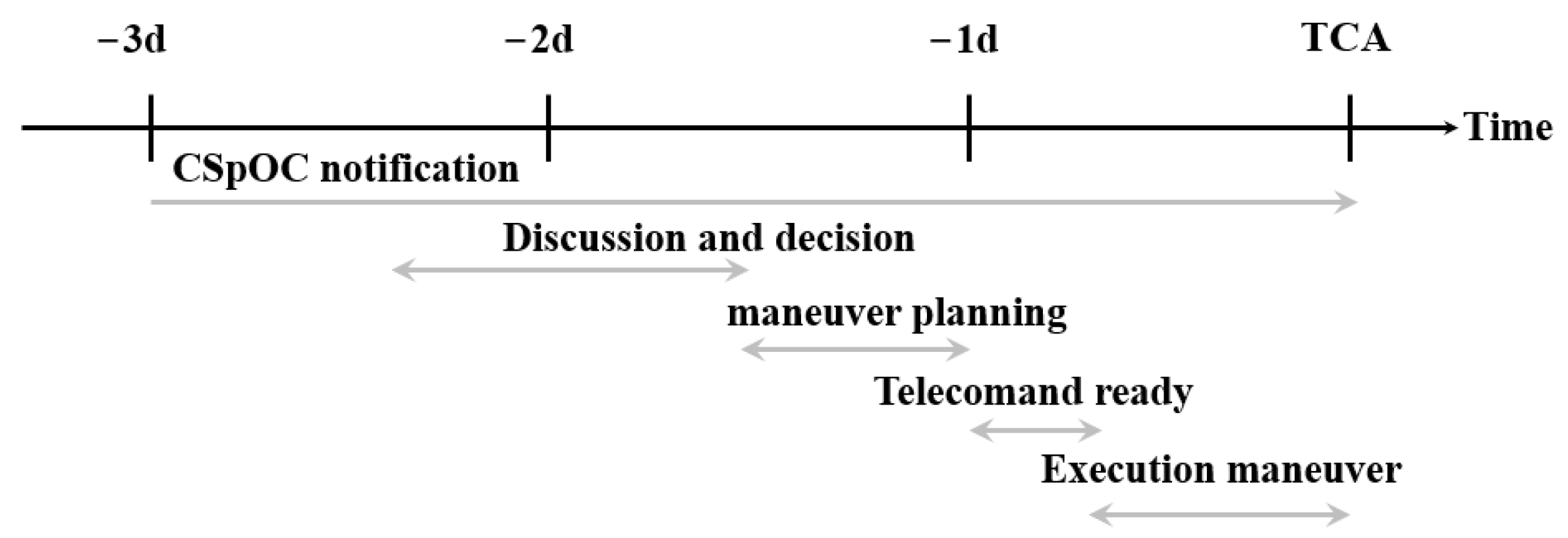
This study explores the potential for establishing a methodology aimed at minimizing the likelihood of a collision involving a CubeSat lacking a propulsion system, solely relying on its active ADCS. The fundamental concept revolves around the idea that altering the satellite’s orientation can influence its cross-sectional area, thereby either increasing or decreasing the drag force it experiences. This adjustment in orientation is intended to occur within the time frame spanning from the initial alert period (7 days prior to the Time of Closest Approach (TCA)) to the recommended limit for maneuvers (2 days before TCA). This action will change the orbital elements of the satellite, modifying the TCA conditions in the following alerts.
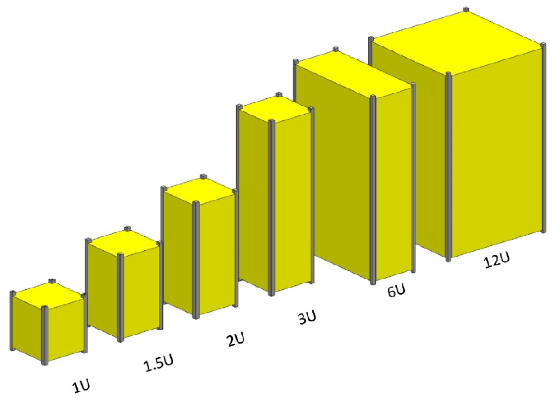
To assess the potential implementation of such a methodology in CubeSats, various formats (including 2U, 3U, and 6U) are subjected to analysis. The insert orbit of Lume-1 serves as the mission scenario. Two additional altitudes are considered in this investigation: one positioned 40 km lower and another situated 80 km lower, analyzing the influence of altitude in the performance. The Lifetime tool within the STK software package is employed to model orbit propagation, considering factors such as cross-sectional area, mass, and the satellite’s initial position.
The primary objective of this part of the methodology is to ascertain the discrepancy in horizontal and vertical satellite positions within a Local Vertical/Local Horizontal (LVLH) reference frame at the TCA. This disparity is then compared against the threshold miss distances prescribed by CDMs to assess the potential utility of employing an ADCS maneuver.
Three different satellites are defined for comparison. SAT-H (semi-major axis of Lume-1 in the orbit insertion: semi-major axis of 6878 km), SAT-M (40 km lower than SAT-H: semi-major axis of 6836 km), and SAT-L (80 km lower than SAT-H, semi-major axis of 6798 km).
The drag force computation relies significantly on the cross-sectional area in the direction of velocity, also known as the drag area. This cross-sectional area varies according to the orientation of the satellite, which can be controlled by the ADCS. Specifically, 2U and 3U CubeSats can adopt two different orientations, resulting in either a 1-unit or 2-unit face area for 2U CubeSats and a 1-unit or 3-unit face area for 3U CubeSats. In contrast, 6U CubeSats offer three possible orientation options, resulting in drag areas of 2-unit face area, 3-unit face area, or 6-unit face area.
It is worth noting that CubeSats adhere to a constrained mass budget, allowing for an estimated mass of 1 kg per unit. Consequently, a 2U CubeSat will have a mass of 2 kg, a 3U CubeSat will weigh 3 kg, and a 6U CubeSat will carry a mass of 6 kg (Table 3). Three different states, equivalent in drag force, A, B and C, can be defined considering the drag area–mass ratio. As an illustrative example, when calculating drag effects, a 6U satellite oriented with its 2-unit face aligned in the direction of velocity produces an equivalent impact to that of a 2U satellite oriented with its 1-unit face directed toward the velocity vector. This equivalence arises because the drag area-to-mass ratio remains constant in both cases.
Collision avoidance needs maneuvering, which means that the employment of the ADCS for this purpose must be expressed in terms of specific maneuvers. In the context of the satellites under examination, three distinct maneuvers are identified: for 2U satellites, a maneuver involves altering the orientation from the 1-unit face to the 2-unit face or vice versa; in the case of 3U satellites, a maneuver consists of transitioning the orientation from the 1-unit face to the 3-unit face or vice versa; and for 6U satellites, maneuvers can encompass changing the orientation from the 2-unit face to the 3-unit face or vice versa, from the 2-unit face to the 6-unit face or vice versa, and from the 3-unit face to the 6-unit face or vice versa.
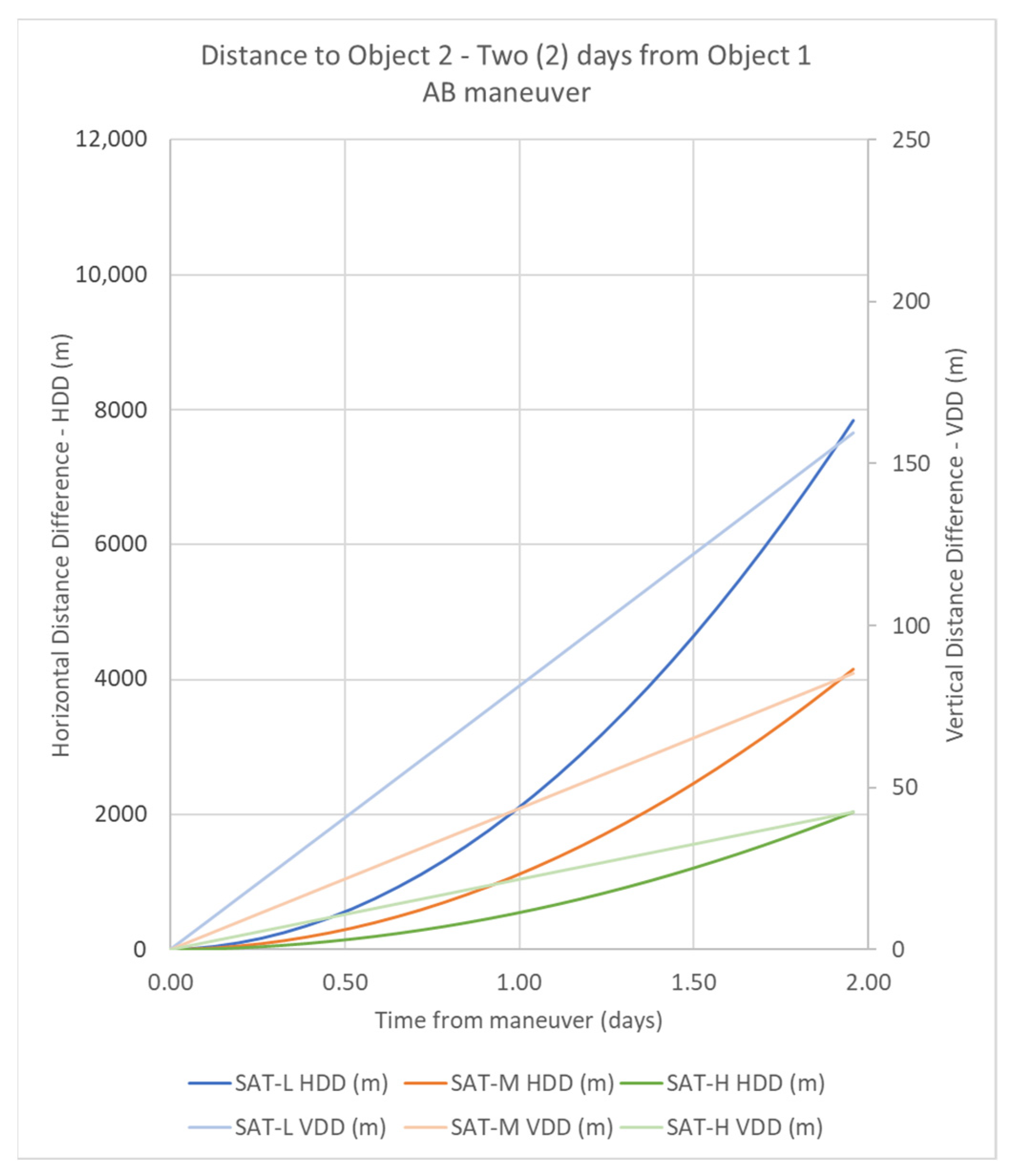
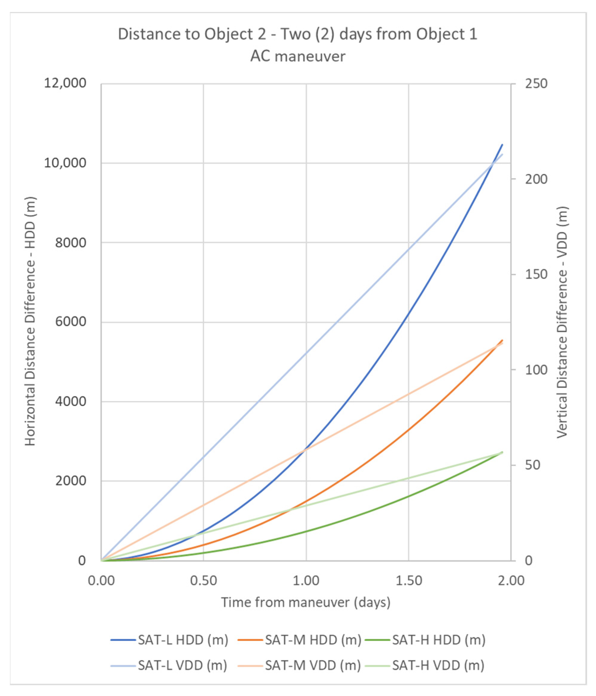
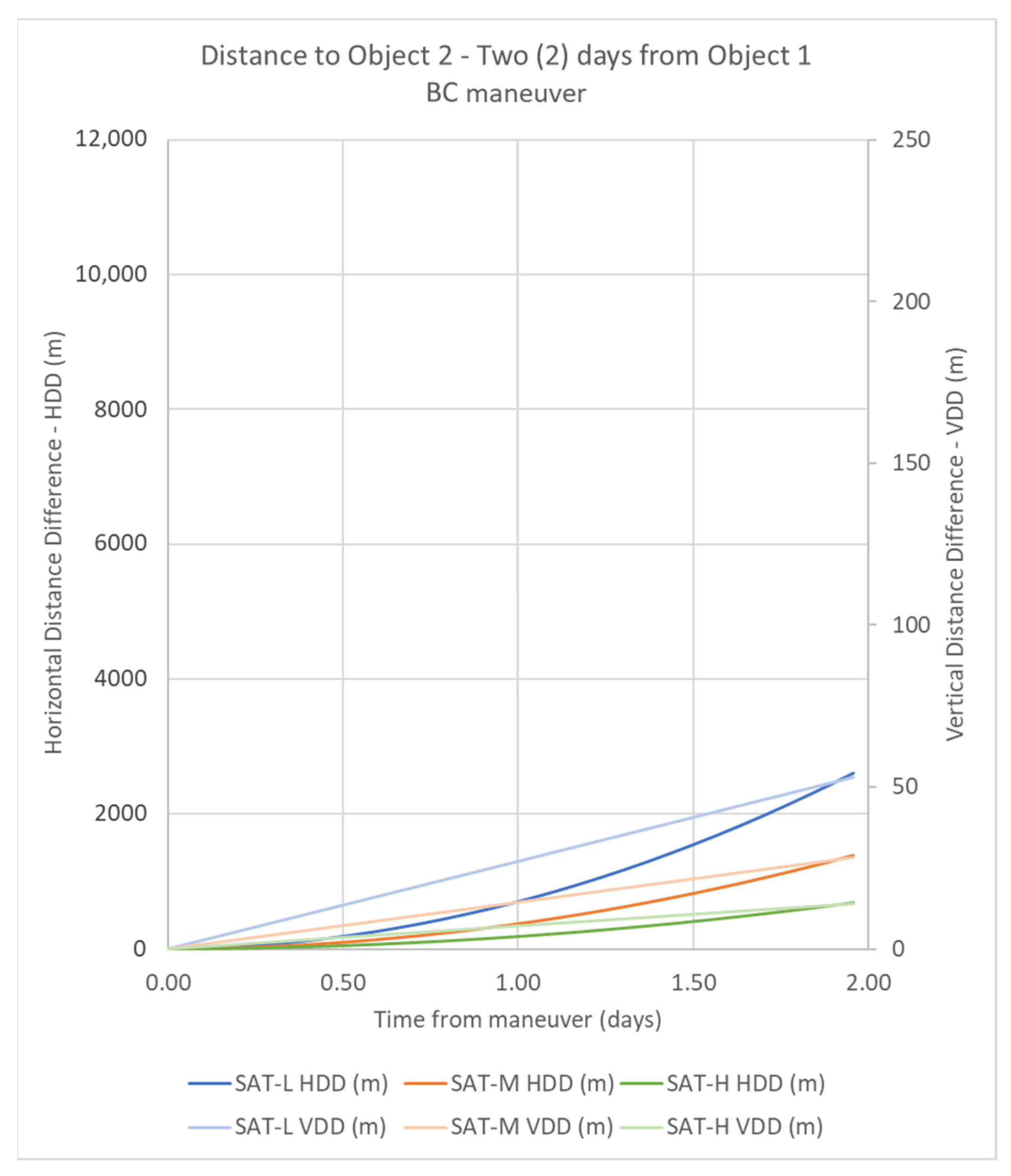
These pairs of maneuvers yield similar effects but with opposing outcomes. When we increase the drag area, it leads to a reduction in the semi-major axis and the period of the osculating orbit over time, compared to the values when the orientation remains unchanged. Conversely, when we decrease the drag area, it results in a larger semi-major axis and period than what would be expected without the maneuver. Consequently, after a period of time, the satellite will be situated lower or higher than initially anticipated, giving rise to what we term the Vertical Distance Difference (VDD).
Furthermore, these maneuvers also impact the overall distance traveled by the satellites. Surprisingly, an increase in the drag area leads to an acceleration in velocity, owing to the reduced period of the osculating orbit. Consequently, the satellite covers a greater distance than expected without the maneuver. Conversely, decreasing the drag area has the opposite effect, causing a reduction in velocity and, consequently, a shorter traveled distance. This phenomenon is referred to as the Horizontal Distance Difference (HDD).
In summary, the possible maneuvers are consolidated in Table 4, where we have three distinct maneuvers to analyze: AB, AC, and BC. In this table, the initial and final position states are shown, corresponding to a maneuver named after the combinations of both states (i.e., initial A position and final B position results in AB maneuver that can be applied to 2U and 6U CubeSats). Also, interchangeability between AB and BA maneuvers (i.e.) was considered because they would have the same effect but in opposite directions. These maneuvers exhibit intricate interactions between drag area, orbital parameters, and satellite trajectories, contributing to a comprehensive understanding of satellite behavior in collision avoidance scenarios.
The calculation of drag is conducted by utilizing the parameters incorporated within the STK Lifetime tool. This calculation encompasses both atmospheric and solar radiation drags. However, for the specific scope of this study, we focus solely on adjusting atmospheric drag parameters, while maintaining default data for solar flux pressure.
To establish a baseline for drag coefficient, a value of 2.2 is set, aligning with the typical default value for conventional satellites. While this value may appear somewhat elevated for CubeSats, it is within the same order of magnitude. The computation of atmospheric density is derived from the U.S. 1976 Standard Atmosphere model [24], ensuring accuracy and reliability.
To account for the diverse scenarios under examination, modifications are applied to the drag area and mass, as outlined in Table 3. These modifications serve as the foundation for the computation of drag force, including the effects of atmospheric drag force acceleration (1), which are then incorporated into the governing equations. This meticulous adjustment of parameters allows us to comprehensively analyze how variations in drag area and mass influence satellite behavior in different scenarios, contributing valuable insights to our study.
a d r a g = 1 2 ρ V 2 C D S m
The drag integration process is executed through the Lifetime tool, employing a meticulous approach involving nine-point Gaussian quadratures per orbit. To enhance precision, we set the value of “n” to 6. This process is pivotal for determining the satellite’s lifetime, as it approximates the integration of slowly evolving orbit elements over time.
The methodology involves integrating across a single orbit to establish the rate of change for each variable. Subsequently, this rate is assumed to remain constant for a specific number of orbits during each calculation. To further elevate the accuracy of this procedure, the integration process for a single orbit is subdivided into six sub-arcs, each maintaining a constant angular measure (in true anomaly, not time). Within each of these sub-arcs, a nine-point Gaussian quadrature is employed, signifying the presence of nine sample points for precise integration.

3.3. Control Algorithm

In this section, the fundamental control mechanism that drives the evasion maneuver in CubeSats will be detailed, focusing on the use of the reaction wheel. This essential component plays a key role in the CubeSat’s ability to modify its orientation, a critical requirement for controlled ballistic coefficient change. This strategy is integrated into a holistic approach that is based on the application of the extended Kalman filter (EKF). The application of this filter allows optimizing the precision of the CubeSat state estimates, thus enabling an effective and precise evasion maneuver in the face of the threat of collisions with space debris. The CubeSat’s reaction wheel control mechanism becomes the driving force of the evasion maneuver by allowing calculated changes in the satellite’s orientation. This capability is exploited to modify the ballistic coefficient, thus contributing to slight adjustments in orbital height and, consequently, mitigating the risk of collisions. The entire process is managed in a coordinated manner using the EKF.
In applications involving linear systems with known dynamics and Gaussian noise, the Kalman filter (KF) has become the tool par excellence. Its nonlinear counterparts, namely the EKF and the unscented Kalman filter (UKF), have found applications in real-time orientation estimation in various domains, despite their challenging implementation. In an effort to circumvent the complexities associated with the linearization procedure and the challenges posed by the EKF and UKF, this study presents a two-step filter architecture designed to mitigate noise and improve filter performance. In the first phase, the information provided by the Inertial Measurement Unit (IMU) (angular acceleration) is obtained in its quaternion form; this quaternion is then utilized as state vector in the KF, in order to determine the corresponding observation vector. With this precise value of the attitude of the spacecraft, the control law is applied to a linear quadratic regulator that implements the orientation control of the CubeSat to implement the collision avoidance maneuver.
The quaternion can be defined as:
Q = q 0 q 1 q 2 q 3
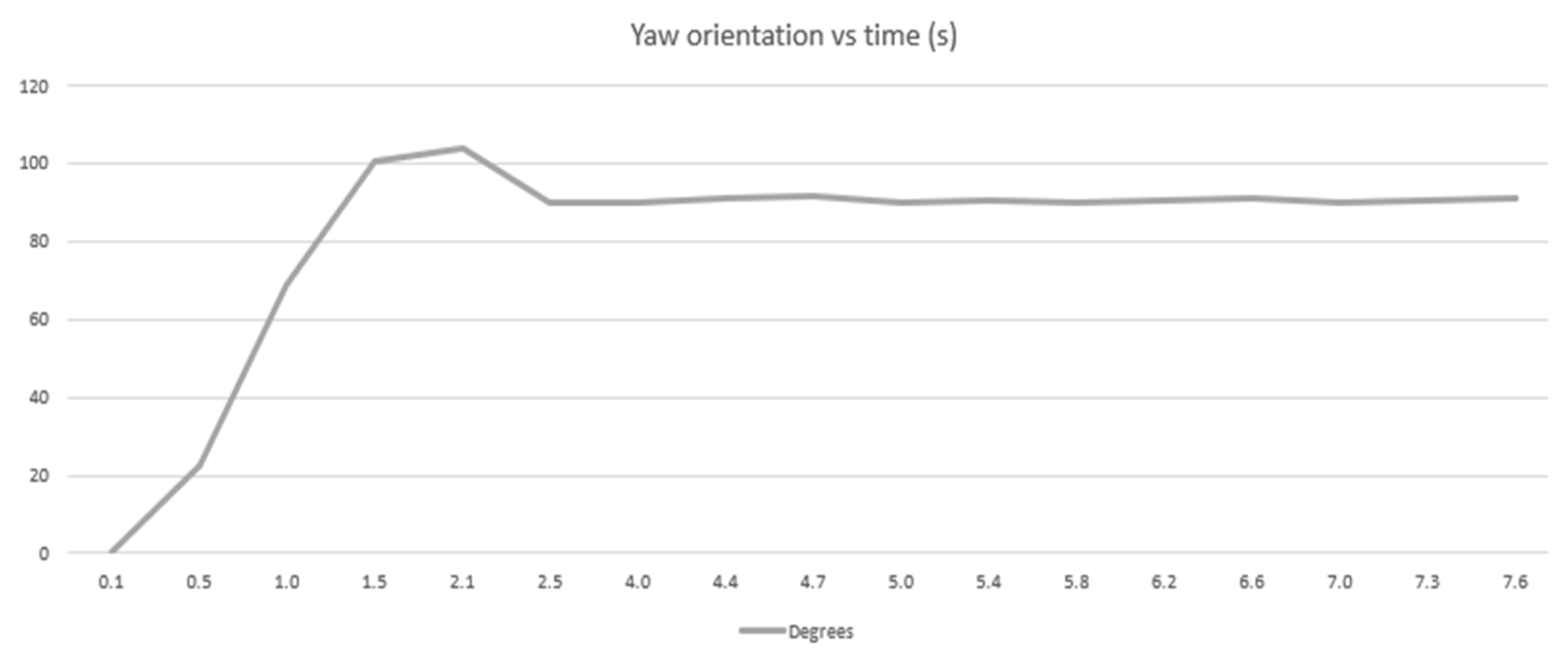
And, therefore, the Yaw Euler angle can be found as:
φ = tan 1 2 ·   ( q 0 q 3 + q 1 q 2 )   1 2 ( q 2 2 + q 3 2 )
The next step is to create the dynamic model in discrete time, rebuilding the signal using the attitude information obtained through the IMU, solving the uncertainty that comes from the noise in the measurement and the common bias that those reads come with. The dynamic equation that describes the attitude of the CubeSat can be written as:
d ω d t = I 1 .   ( ω . I . w )
where ω is the angular velocity, I is the velocity tensor, and is the resultant of the torques that the spacecraft is suffering, including the reaction wheel action and the perturbations.
Written in quaternion form, and discretizing the previous equation, we can rewrite the equations as:
I k + 1 = I ω k + Δ t ( [ I ω k ] x ω k + t )
Q k + 1 = Q t 2 exp ( ) I ω k + Δ t ( [ I ω k ] x ω k + t )
And the required dynamics that the spacecraft is demanded can be written as [24]:
Q ˙ r = Q d 2 0 w r T ω ω
We can now introduce the Quaternion Estimator to build the reconstruction of the attitude using the sensors in the IMU of the CubeSat, to provide the input for the KF. The idea is to minimize a cost function as:
C ( R ) = 1 2 j = 1 n s j v j B R T v j H 2
where v j B represents the normalized body-frame vectors that represent the j measurements, v j H is the corresponding inertial ones, and sj is the level of confidence for each of the measurements [25]. If we now define the observation vectors as:
p j = s j j = 1 n s j
We can then introduce the attitude profile matrix:
L = j = 1 n p j v j B v j H T
So that we can finally obtain:
Q f = 1 y j + y 2 y 0 y
where y 0 is a scalar and y is a vector given by:
y 0 = det ( ξ m a x + T r B I C
y = ( α 1 I + α 2 C + C 2 )
Having the Davenport matrix as:
C = T r { L } x T x C T r L I
where:
x = j = 1 n p j v j B × v j B
And:
α 1 =   ξ M a x 2 T r L 2 + T r [ a d j C ]
α 2 =   ξ M a x T r C
Having I as the identity matrix, C the sum of the L matrix and its transpose, and ξ M a x is the greatest characteristic of the Davenport matrix.
Now that the reconstruction step has been performed, the next phase will filter the uncertainties of the attitude estimated using an EKF. The EKF is an analytical method employed for the estimation of attitude in dynamic systems, leveraging both prior knowledge of the attitude and real-time sensor measurements to calculate the current attitude of the system. EKF has been chosen because of its ability to handle nonlinear systems by linearizing the differential equations that describe the system’s dynamics, addressing KF limitations by introducing a linearization step. By the use of linearization of the nonlinear equations (between the system’s attitude parameters and the sensor measurements) around the current estimated state, it will enable the application of standard Kalman filter techniques, providing accurate estimates even in the presence of nonlinear dynamics. The EKF will iteratively update its estimates, combining the information from both the prediction based on the system’s dynamics and the correction based on the actual sensor measurements, refining the attitude estimates over time.
Define the expected measurement on the predicted state x k + 1 ,   as:
y k = f 1 ( x k + 1 ,   ,   n k )
where f 1 is a non-linear differential function and n k is the measurement noise. And, having:
x k + 1 = f 2 ( x k ,   ,   m k )
where f 2 is a non-linear differential function and m k is the process noise.
The state model serves to forecast the subsequent state of a dynamic system based on the current state, while the measurement model anticipates the observation vector using the projected state. In the context of the EKF, the linearization process is applied around an estimated orientation that undergoes continuous updates through sensor observations. At each iteration, the EKF undertakes the process of linearization of the differential equations. This involves approximating the nonlinear relationships between system variables by their linear counterparts, allowing the EKF to iteratively update predictions and measurements with improved accuracy as it refines its estimation of the system’s state over time.
The filter uses the first initial state x k 1 , P k 1 as the state covariance matrix, z k as the measurements given by the IMU, Q k as the process noise covariance matrix, and R k as the measurement noise covariance matrix.
The maximum number of iterations of the process, denoted as N, is a parameter in the EKF that may be contingent on the specified error threshold or defined by the system designer. It is worth noting that all input parameters, excluding sensor measurements, were initialized based on certain assumptions, as in common scenarios where covariance data are unavailable. The EKF algorithm can be conceptually divided into two primary steps: prediction and measurement update.
During the prediction step, the algorithm forecasts the state using the past state ( x k 1 ) and the linearized function F (the Jacobian matrix of f ( x k 1 , k ) ) to find F k i :
x k + 1 = F k i x k 1
And, simultaneously, the state covariance matrix P is predicted based on F.
P k + 1 = F k i P k 1 ( F k i ) T + Q k
Subsequently, in the measurement update step, the differential equation of the measurement model is linearized by computing the Jacobian matrix h ( x k + 1 , k ) , to find H k i . This linearization is crucial for calculating the measurement prediction and determining the Kalman gain (K), given as:
K k i = P k i H k i T H k i P k + 1 i H k i T + R k i
The Kalman gain, along with the sensor measurements and the expected measurement based on the predicted state (y) is then employed to update the predicted state vector:
y k i = H k i x k + 1
Furthermore, the state covariance matrix undergoes an update using the gain (K) and the linearized observation matrix (H). The optimal estimate, denoted as x_k, represents the output of the filter and serves as the refined estimation of the system’s current state. This iterative process continues until the maximum number of iterations is reached, as determined by either the specified error threshold or the designer’s predetermined limit. The inclusion of the prediction and measurement update steps, along with the iterative nature of the algorithm, enables the EKF to continually refine its estimates, providing an optimal and accurate representation of the system’s evolving state over time.

4. Results and Discussion

4.1. Distances Calculation

The results of the simulations for the different maneuvers defined are presented in this section. HDD and VDD are computed for two days after the maneuver. Simulations are grouped by type of maneuver: AB, AC, and BC. Results are presented in figures where the axes have the same range, for the aim of visual comparison.

4.1.1. Maneuver AB

Maneuver AB is performed when the CubeSat changes its orientation from the initial position A to the final position B. This maneuver represents two different scenarios: for 2U CubSat from 2-unit drag face to 1-unit drag face and vice versa, or for 6U CubSat from 6-unit drag face to 3-unit drag face and vice versa. Figure 6 shows the results of HDD and VDD for the three different orbits under study.
The three CubeSats show similar evolutions during the two days regarding HDD and VDD, but with different effects. SAT-L, the one with the lowest orbit, shows the highest distance in each instant, and SAT-H, the one with the highest orbit, shows the lowest distance in each instant. SAT-M shows intermediate distances, between SAT-L and SAT-H. In all cases, the VDD varies proportionally with time and HDD shows an exponential behavior. The maximum VDD achieved by the maneuver corresponds to SAT-L, with 159.67 m, an intermediate value of VDD is reached by SAT-M with 85.36 m, and the minimum VDD is 42.33 m for SAT-H. On the other hand, the maximum HDD achieved by the maneuver corresponds to SAT-L, with 7.84 km, an intermediate value of HDD is reached by SAT-M with 4.16 km, and the minimum HDD is 2.06 km for SAT-H.

4.1.2. Maneuver AC

Maneuver AC is performed when the CubeSat changes its orientation from the initial position A to the final position C. This maneuver represents two different scenarios: for 3U CubSat from 3-unit drag face to 1-unit drag face and vice versa, or for 6U CubSat from 6-unit drag face to 2-unit drag face and vice versa. Figure 7 shows the results of HDD and VDD for the three different orbits under study.
The three CubeSats show similar evolutions during the two days regarding HDD and VDD, but with different effects. SAT-L, the one with the lowest orbit, shows the highest distance in each instant, and SAT-H, the one with the highest orbit, shows the lowest distance in each instant. SAT-M shows intermediate distances, between SAT-L and SAT-H. In all cases, the VDD varies proportionally with time and HDD shows an exponential behavior. The maximum VDD achieved by the maneuver corresponds to SAT-L, with 212.80 m, an intermediate value of VDD is reached by SAT-M with 113.79 m, and the minimum VDD is 56.43 m for SAT-H. On the other hand, the maximum HDD achieved by the maneuver corresponds to SAT-L, with 10.45 km, an intermediate value of HDD is reached by SAT-M with 5.54 km, and the minimum HDD is 2.72 km for SAT-H.

4.1.3. Maneuver BC

Maneuver BC is performed when the CubeSat changes its orientation from the initial position B to the final position C. This maneuver represents two different scenarios: for 6U CubeSat from 3-unit drag face to 2-unit drag face and vice versa. Figure 8 shows the results of HDD and VDD for the three different orbits under study.
The three CubeSats show similar evolutions during the two days regarding HDD and VDD, but with different effects. SAT-L, the one with the lowest orbit, shows the highest distance in each instant, and SAT-H, the one with the highest orbit, shows the lowest distance in each instant. SAT-M shows intermediate distances, between SAT-L and SAT-H. In all cases, the VDD varies proportionally with time and HDD shows an exponential behavior. The maximum VDD achieved by the maneuver corresponds to SAT-L, with 53.13 m, an intermediate value of VDD is reached by SAT-M with 28.42 m, and the minimum VDD is 14.10 m for SAT-H. On the other hand, the maximum HDD achieved by the maneuver corresponds to SAT-L, with 2.61 km, an intermediate value of HDD is reached by SAT-M with 1.38 km, and the minimum HDD is 0.68 km for SAT-H.

4.2. Laboratory Test

In this section, the experimental validation of the EKF algorithm in executing collision avoidance maneuvers using the reaction wheel is performed. An EQM of the CubeSat was used as a prototype, allowing to assess the performance of the algorithm in a controlled environment before deploying the solution to the real operational mission. The focus was on evaluating how effectively the filter, when integrated with the reaction wheel mechanism, can maneuver the spacecraft to avoid potential collisions with space debris.
Figure 9 displays the nanosatellite based on the successful CubeSat standard, weighing around 2 kg. This CubeSat contains the following typical spacecraft subsystems: Electrical Power, Command and Data Handling, Attitude Determination, and Control and Structure. It features a Wi-Fi communication system allowing connection with a PC, which was used to operate and control the experiments.
The experiments were based on the application of a control law to maneuver and modify the orientation of the CubeSat in order to modify the ballistic coefficient and thus reduce the height, avoiding possible contact with debris. The action must be fast and controlled, so as to avoid over oscillations, having a fast-settling time, and a steady state error tending to zero.
As Figure 10 displays, the rise time is obtained at 1.6 s after imposing the law control, with a peak overshot of 14% (in a peak time of 1.9 s), and a settling time of 2.8 s.

4.3. Discussion

Table 5 shows a summary of the values of HDD and VDD obtained for a two-day period after maneuver, obtained for the different maneuvers and orbits under study, indicating the semimajor axis of the orbit corresponding to SAT-H, SAT-M, and SAT-L.
The obtained results highlight the varying degrees of effectiveness among the studied maneuvers, with maneuver AC emerging as the most impactful across all three satellites. Conversely, maneuver BC exhibits the least effectiveness. Even in the most challenging scenario, which is represented by maneuver BC for SAT-H, we observe a HDD of 681.72 m and a VDD of 14.10 m. These values represent a 68% and 7% deviation, respectively, when compared to the notification threshold.
When we delve into the comparative analysis of these maneuvers across different satellites, an intriguing trend emerges. It becomes evident that the altitude of the satellite plays a crucial role in the maneuver’s effectiveness. The lower the satellite’s initial altitude, the more pronounced the impact of the maneuver. For instance, when we consider maneuver AC for SAT-L, we witness a substantial HDD of 10,456.91 m and a remarkable VDD of 212.80 m. These figures correspond to a staggering 1045% and 106% deviation, respectively, in relation to the notification threshold.
These findings underscore the nuanced dynamics at play when it comes to collision avoidance maneuvers, emphasizing the significance of tailoring these strategies to the specific characteristics and altitudes of the satellites involved in order to ensure the highest level of effectiveness and safety.
Figure 11 represents the values of HDD and VDD shown in Table 5. It can be seen that HDD and VDD are proportional for each satellite–maneuver combination. They are represented in Figure 11 using different scales for more clarity.
Interpreting Figure 11 and according to Equation (1), drag acceleration is proportional to the atmosphere density and the velocity squared. So, as altitude decreases, atmosphere density increases, so drag acceleration is higher, making the vehicle reduce its velocity faster. Also, the effect of velocity in drag acceleration is more relevant. It is well known that the lower the circular orbit, the higher the orbital velocity, so increasing the velocity when moving to a lower orbit has a higher effect on the drag acceleration, making the vehicle reduce its velocity even faster. So, the tendency that we can appreciate in Figure 11 makes perfect sense, due to the addition of both effects, increase in atmospheric air density and orbital velocity. So, we can conclude that each maneuver analyzed increases HDD and VDD as the altitude decreases, and the increment is exponential due to the variation of the air density and the velocity squared.
Regarding the values obtained for the different combinations, we must come back to the consideration made in Section 3.2, where the cases analysis was imposed for maneuvers between states where the area-to-mass ratio is constant. Also, interchangeability between AB and BA maneuvers (i.e.) was considered because they would have the same effect but in opposite directions. The results obtained, and reflected in Figure 11, confirm that this hypothesis is right, because for all the cases of study the VDD is very small compared with the orbital radius (four orders of magnitude smaller), so the effect in relative change in air density and vehicle velocity can be neglected for the computation of drag acceleration for each combination, according to Equation (1). So, we can consider that the drag acceleration would only depend on the area-to-mass ratio, at the time of analysis.

5. Conclusions

This research has undertaken a comprehensive examination of the feasibility of establishing a methodology aimed at mitigating the risk of collisions involving CubeSats lacking propulsion systems. The methodology hinges on the alteration of the satellite’s orientation, thereby modifying its cross-sectional area, which in turn influences the drag force. This dynamic adjustment has been explored across a spectrum of satellite altitudes within LEO and encompasses three CubeSat formats: 2U, 3U, and 6U. The effects of these orientation changes have been scrutinized in the context of maneuvers recommended two days before the TCA.
For each scenario under investigation, an assessment of the disparity in the satellite’s horizontal and vertical positions within a LVLH reference system at TCA has been conducted. This analysis entails a comparison with the threshold miss distances established by CDMs. The results are noteworthy, revealing a minimum deviation of 7% and a maximum deviation of 106% in the VDD, along with a minimum of 68% and a maximum of 1045% in the HDD, all concerning the notification threshold.
These findings provide compelling support for the practicality of the proposed collision avoidance methodology tailored specifically for CubeSats, utilizing their ADCS system. Ongoing efforts in this research endeavor are now focused on investigating the rate at which the ADCS system can execute these maneuvers and assessing the time required for their implementation, further advancing our understanding and applicability of this innovative approach to CubeSat collision avoidance.
An application of the application of the Extended Kalman Filter (EKF) is introduced, specifically customized for the precise control of reaction wheels in CubeSats. Unlike conventional applications, this algorithm has been meticulously designed to address the inherent constraints associated with CubeSats, including restricted computational resources, stringent power limitations, and the imperative consideration of weight. Recognizing that CubeSats typically operate within these challenging parameters, the algorithm’s adaptability to such constraints makes it a noteworthy advancement in the field. Rigorous testing in a laboratory setting has substantiated the algorithm’s efficacy, revealing its capability to perform seamlessly under realistic conditions. The validation process not only underscores the algorithm’s reliability but also positions it as a promising solution for the intricate task of managing the attitude control in CubeSats.
Of particular significance is the algorithm’s emphasis on computational efficiency and power frugality, two critical attributes in the context of CubeSat technology. Given the miniature scale of CubeSats and their reliance on limited resources, the algorithm’s efficiency becomes paramount. The research team’s dedication to developing a methodology that not only meets performance expectations but also operates within stringent power constraints sets a new standard for attitude control in small satellite systems. By demonstrating its computational efficiency and power thriftiness, this research not only contributes a valuable tool for CubeSat missions but also marks a substantial stride toward overcoming the persistent challenges associated with resource-constrained environments in the realm of space exploration.

Author Contributions

Methodology, P.O.-C., C.C. and F.A.-A.; Software, P.O.-C.; Validation, C.C.; Formal analysis, D.G.-R.; Investigation, D.G.-R.; Resources, P.O.-C., C.C. and F.A.-A.; Writing—original draft, D.G.-R. and P.O.-C.; Writing—review & editing, C.C. and F.A.-A.; Project administration, F.A.-A. All authors have read and agreed to the published version of the manuscript.

Funding

This research received no external funding.

Institutional Review Board Statement

Not applicable.

Informed Consent Statement

Not applicable.

Data Availability Statement

Data available on request due to restrictions.

Acknowledgments

The authors thank the University of Vigo for the use of the Educational version of ANSYS STK product.

Conflicts of Interest

The authors declare no conflict of interest.

Nomenclature

adragdrag force acceleration
ρatmospheric density
Vsatellite velocity
CDdrag coefficient
Sdrag area
msatellite mass
φ Yaw angle
ωAngular velocity
QQuaternioun
K k i Kalman gain
Acronyms/Abbreviations
LEOLow Earth Orbit
ADCSAttitude Determination and Control System
UUnit
STKSystem Tool Kit
CDMConjunction Data Message
ESAEuropean Space Agency
ESOCEuropean Space Operations Centre
IADCInter-Agency Space Debris Coordination Committee
COPUOSCommittee on the Peaceful Uses of Outer Space
ISOInternational Organisation for Standardisation
NASANational Aeronautics and Space Administration
JSpOCJoint Space Operations Center
SSNSpace Surveillance Network
ISSInternational Space Station
SSTSpace Surveillance and Tracking
CDSCubeSat Design Specification
UAVUnmanned Aerial Vehicle
SGP4Standard General Perturbations Satellite Orbit Model 4
HPOPHigh-Precision Orbit Propagator
CAConjunction Assessment
TCATime of Closest Approach
LVLHLocal Vertical, Local Horizontal
TLETwo-Line Element
VDDVertical Distance Difference
HDDHorizontal Distance Difference
EQMEngineering Qualification Model
GISTDAGeo-Informatics and Space Technology Development Agency
CDSCubeSat Design Specification
UAVUnmanned Aerial Vehicle
SSOSun Synchronous Orbit
KFKalman filter
EKFextended Kalman filter
UKFunscented Kalman filter
IMUInertial Measurement Unit
RWReaction wheel

References

  1. NASA Website: Space Debris and Human Spacecraft. Available online: https://www.nasa.gov/mission_pages/station/news/orbital_debris.html (accessed on 25 July 2022).
  2. O’Reilly, D. Scopus. Available online: https://www.scopus.com/record/display.uri?eid=2-s2.0-85099955214&origin=resultslist&sort=plf-f&src=s&st1=collision+avoidance+cubesat&sid=b08453557fa8a10a6244f7da8f05a4dc&sot=b&sdt=b&sl=42&s=TITLE-ABS-KEY%28collision+avoidance+cubesat%29&relpos=5&citeCnt=3 (accessed on 11 February 2023).
  3. S.D. Office. ESA’s Annual Space Environment Report; The European Space Agency: Darmstadt, Germany, 2022. [Google Scholar]
  4. ESA’s Space Debris Office. Available online: https://www.esa.int/Safety_Security/Space_Debris/Space_debris_by_the_numbers (accessed on 9 May 2022).
  5. Murtaza, A.; Pirzada SJ, H.; Xu, T.; Jianwei, L. Orbital Debris Threat for Space Sustainability and Way Forward. IEEE Access 2020, 8, 61000–61019. [Google Scholar] [CrossRef]
  6. NASA. Top ten satellite breakups reevaluated. In Orbital Debris Quarterly News; National Aeronautics and Space Administration: Washington, DC, USA, 2016; Volume 20. [Google Scholar]
  7. Liou, J.C.; Johnson, N.L. Characterization of the cataloged Fengyun-1C fragments and their. Adv. Space Res. 2009, 43, 1407–1415. [Google Scholar] [CrossRef]
  8. The Aerospace Corporation. Understanding Space Debris Causes, Mitigations and Issues; Crosslink: Los Angeles, CA, USA, 2015; Volume 16. [Google Scholar]
  9. Kessler, D.J.; Cour-Palais, B.G. Collision Frequency of Satellites: The Creation of a Debris Belt. J. Geophys. Res. 1978, 83, 2637–2646. [Google Scholar] [CrossRef]
  10. Kessler, D.J.; Johnson, N.L.; Liou, J.C.; Matney, M. The Kessler Syndrome: Implications to Future. Am. Astronaut. Soc. 2010, 137, 2010. [Google Scholar]
  11. Available online: https://www.iadc-home.org/ (accessed on 15 May 2023).
  12. COPUOS. Available online: https://www.unoosa.org/oosa/en/ourwork/topics/space-debris/compendium.html (accessed on 5 May 2023).
  13. Channumsin, S. Collision avoidance strategies and conjunction risk assessment analysis tool at GISTDA. J. Space Saf. Eng. 2019, 7, 268–273. [Google Scholar] [CrossRef]
  14. CCSDS 508.0-B-1. Conjunction Data Message; CCSDS: Washington DC, USA, 2023. [Google Scholar]
  15. C.P.C. Lab. Available online: https://www.cubesat.org/s/CDS-REV14_1-2022-02-09.pdf (accessed on 5 March 2022).
  16. Kulu, E. Nanosats Database. 2023. Available online: https://www.nanosats.eu/ (accessed on 5 May 2023).
  17. Pelton, J.N. Overview of Small Satellite Technology and Systems Design. In Handbook of Small Satellites: Technology, Design, Manufacture, Applications, Economics and Regulation; Springer: Arlington, TX, USA, 2020; pp. 125–144. [Google Scholar]
  18. Swei, S.S.-M.; Westfall, A.J. Attitude control system design for cubesats configured with exo-brake parachute. In Proceedings of the AIAA Space and Astronautics Forum and Exposition, Long Beach, CA, USA, 13–16 September 2016; AIAA SPACE: Long Beach, CA, USA, 2016. [Google Scholar]
  19. NASA. TechEdSat-4 with Deployed Exobrake. 2015. Available online: https://www.nasa.gov/image-article/techedsat-4-with-deployed-exobrake/ (accessed on 15 August 2022).
  20. ESA. ESA—SPACE SAFETY—Deploying a Drag Sail. 2021. Available online: https://www.esa.int/ESA_Multimedia/Images/2021/04/Deploying_a_drag_sail#:~:text=ESA%E2%80%99s%20General%20Support%20Technology%20Programme%20and%20the%20space,will%20burn%20up%20after%20its%20mission%20is%20over (accessed on 15 August 2022).
  21. Ansys Systems Tool Kit (STK). Available online: https://www.agi.com/products/stk (accessed on 22 July 2022).
  22. Pelton, J.N. Stability, pointing, and orientation. In Handbook of Small Satellites: Technology, Design, Manufacture, Applications, Economics and Regulation; Springer: Arlington, TX, USA, 2020; pp. 145–188. [Google Scholar]
  23. Alen Space. LUME-1: Nanosatellite of the University of Vigo for Firefighting. 2018. Available online: https://alen.space/lume-1-launch/ (accessed on 15 August 2022).
  24. National Oceanic and Atmospheric Administration. US Standard Atmosphere; National Oceanic and Atmospheric Administration: Washington, DC, USA, 1976.
  25. Lefferts, E.J.; Markley, F.L.; Shuster, M.D. Kalman filtering for spacecraft attitude estimation. J. Guid. Control. Dyn. 1982, 5, 417–429. [Google Scholar] [CrossRef]
Figure 1. Evolution of number of objects. Reprinted from ESA’s Annual Space Environment Report, 12 September 2023 [3].
Applsci 13 12388 g001
Figure 2. Example of timeline of collision avoidance operational activities [14].
Applsci 13 12388 g002
Figure 3. CubeSat family (1U–12U).
Applsci 13 12388 g003
Figure 4. NASA TechEdSat-4 with deployed exo-brake parachute [19].
Applsci 13 12388 g004
Figure 5. Lume 1 2U-satellite [23].
Applsci 13 12388 g005
Figure 6. Results for two days after Maneuver AB for all satellites under study.
Applsci 13 12388 g006
Figure 7. Results for two days after Maneuver AC for all satellites under study.
Applsci 13 12388 g007
Figure 8. Results for two days after Maneuver BC for all satellites under study.
Applsci 13 12388 g008
Figure 9. The CubeSat used in the laboratory tests. It is a nanosatellite based on the Cubesat standard, with an easy-to-assemble lightweight structure that allows the integration of custom subsystems and payloads. The attitude determination and control subsystem allow the implementation of different control laws, including a magnetometer, two magnetotorquers, a reaction wheel, and four sun sensors.
Applsci 13 12388 g009
Figure 10. Evolution of the attitude of the spacecraft with time, under the control law. The delay time (time to achieve the 50% of the final value is near a second; the rising time of the signal is achieved almost in two seconds, while settling time rounds 2.5 s with a maximum signal value with respect to the final value under 5%.
Applsci 13 12388 g010
Figure 11. HDD and VDD for satellite-maneuver combinations.
Applsci 13 12388 g011
Table 1. Top 10 breakups, January 2016.
RankInternational DesignatorCommon NameYear of BreakupAltitude of BreakupCataloged DebrisDebris in OrbitAssessed Cause of Breakup
11999-25Fengyun-1C71200785034282880intentional collision
21993-36Cosmos 2251200979016681141accidental collision
31994-29STEP-1 Rocket Body199662575484accidental explosion
41997-51Iridium 332009790628364accidental explosion
52006-26Cosmos 242120084105090unknown
61986-19SPOT-1 Rocket Body198680549832accidental explosion
71965-82OV2-1/LCS 2 Rocket Body196574047333accidental explosion
81999-57CBERS 1/SACI 1 Rocket Body2000740431210accidental explosion
91970-25Nimbus 4 Rocket Body19701075376235accidental explosion
102001-49TES Rocket Body200167037280accidental explosion
Table 2. The larger the debris size, the more dangerous will be the collision.
Debris SizeMass (g) Aluminum SphereKinetic Energy (J)Equivalent TNT (Kg)Energy Similar to
1 mm0.0014710.0003Baseball
3 mm0.03819100.008Bullets
1 cm1.4170,7000.3Falling anvil
5 cm176.78,840,00037Hit by bus
10 cm1413.770,700,000300Large bomb
Table 3. Case studies for 2U, 3U, and 6U CubeSats.
CubeSat FormatDrag Face Drag   Area   ( m 2 m 2 )Mass (kg)Drag Area/Mass (m2/kg)Case Study
2U1U0.0120.005B
2U0.020.010A
3U1U0.0130.003C
3U0.030.010A
6U2U0.0260.003C
3U0.030.005B
6U0.060.010A
Table 4. Type of maneuver for the cases studied.
Initial PositionFinal PositionManeuverCubeSat Format
ABAB2U, 6U
BAAB2U, 6U
ACAC3U, 6U
CAAC3U, 6U
BCBC6U
CBBC6U
Table 5. HDD and VDD for satellite–maneuver combinations.
Orbits/ManeuversSemi-Major Axis (km)VDD (m)HDD (m)
SAT-H-AB6878.7842.332046.32
SAT-M-AB6838.7885.364160.12
SAT-L-AB6798.78159.677845.10
SAT-H_BC6878.7814.10681.72
SAT-M_BC6838.7828.421385.67
SAT-L_BC6798.7853.132611.81
SAT-H_AC6878.7856.432728.04
SAT-M_AC6838.78113.795545.80
SAT-L_AC6798.78212.8010,456.91
Disclaimer/Publisher’s Note: The statements, opinions and data contained in all publications are solely those of the individual author(s) and contributor(s) and not of MDPI and/or the editor(s). MDPI and/or the editor(s) disclaim responsibility for any injury to people or property resulting from any ideas, methods, instructions or products referred to in the content.

