Switchable Fiber Ring Laser Sensor for Air Pressure Based on Mach–Zehnder Interferometer

 , , ,
, , ,  , ,
, ,  , and
, and
Abstract
:1. Introduction
2. Principle of Operation and Its TCFMI Pressure Analysis
3. Results and Discussion
4. Conclusions
Author Contributions
Funding
Institutional Review Board Statement
Informed Consent Statement
Data Availability Statement
Conflicts of Interest
References
- Zhu, J.J.; Zhang, A.P.; Xia, T.H.; He, S.; Xue, W. Fiber-optic high-temperature sensor based on thin-core fiber modal interferometer. IEEE Sens. J. 2010, 10, 1415–1418. [Google Scholar]
- Díaz-Lucas, S.; San-Fabian, N.; Socorro-Leranoz, A.B.; Matias, I.R. Temperature sensor using a multiwavelength erbium-doped fiber ring laser. Hindawi J. Sens. 2017, 2017, 8187451. [Google Scholar]
- Zhou, Y.; Zhou, W.; Chan, C.C.; Wong, W.C.; Shao, L.-Y.; Cheng, J.; Dong, X. Simultaneous measurement of curvature and temperature based on PCF-based interferometer and fiber Bragg grating. Opt. Commun. 2011, 284, 5669–5672. [Google Scholar] [CrossRef]
- Pei, L.; Liu, C.; Li, J.; Zheng, J.; Yu, S.; Wu, L. Highly sensitive axial strain fiber laser sensor based on all-fiber acousto-optic tunable filter. IEEE Photonics Technol. Lett. 2014, 26, 2430–2433. [Google Scholar] [CrossRef]
- Liu, Z.; Zhang, X.; Gong, Z.; Zhang, Y.; Peng, W. Fiber ring laser-based displacement sensor. IEEE Photonics Technol. Lett. 2016, 28, 1723–1726. [Google Scholar] [CrossRef]
- Cheng, X.; Bonefacino, J.; Guan, B.O.; Tam, H.Y. All-polymer fiber-optic pH sensor. Opt. Express 2018, 26, 14610–14616. [Google Scholar] [CrossRef] [PubMed]
- Kronenberg, P.; Rastogi, P.K.; Giaccari, P.; Limberger, H.G. Relative humidity sensor with optical fiber Bragg gratings. Opt. Lett. 2002, 27, 1385–1387. [Google Scholar] [CrossRef] [PubMed]
- Town, G.E.; Yuan, W.; McCosker, R.; Bang, O. Microstructured optical fiber refractive index sensor. Opt. Lett. 2010, 35, 856–858. [Google Scholar] [CrossRef] [PubMed]
- Berthold, J.W. Historical review of microbend fiber-optic sensors. J. Light. Technol. 1995, 13, 1193–1199. [Google Scholar] [CrossRef]
- Dong, X.; Liu, Y.; Liu, Z.; Dong, X. Simultaneous displacement and temperature measurement with cantilever-based fiber Bragg grating sensor. Opt. Commun. 2001, 192, 213–217. [Google Scholar] [CrossRef]
- Wu, C.; Fu, H.Y.; Qureshi, K.K.; Guan, B.O.; Tam, H.Y. High-pressure and high-temperature characteristics of a Fabry–Perot interferometer based on photonic crystal fiber. Opt. Lett. 2011, 36, 412–414. [Google Scholar] [CrossRef] [PubMed]
- Jin, L.; Guan, B.O.; Wei, H. Sensitivity characteristics of Fabry-Perot pressure sensors based on hollow-core microstructured fibers. J. Light. Technol. 2013, 31, 2526–2532. [Google Scholar]
- Yu, Q.; Zhou, X. Pressure sensor based on the fiber-optic extrinsic Fabry-Perot interferometer. Photonic Sens. 2011, 1, 72–83. [Google Scholar] [CrossRef]
- Zhu, Y.; Wang, A. Miniature fiber-optic pressure sensor. IEEE Photonics Technol. Lett. 2005, 17, 447–449. [Google Scholar]
- Bock, W.J.; Chen, J.; Mikulic, P.; Eftimov, T. A novel fiber-optic tapered long-period grating sensor for pressure monitoring. IEEE Trans. Instrum. Meas. 2007, 56, 1176–1180. [Google Scholar] [CrossRef]
- Vitoria, I.; Zamarreño, C.R.; Ozcariz, A.; Matias, I.R. Fiber optic gas sensors based on lossy mode resonances and sensing materials used therefor: A comprehensive review. Sensors 2021, 21, 731. [Google Scholar] [CrossRef]
- Zhou, J.; Liao, C.; Wang, Y.; Yin, G.; Zhong, X.; Yang, K.; Sun, B.; Wang, G.; Li, Z. Simultaneous measurement of strain and temperature by employing fiber Mach-Zehnder interferometer. Opt. Express 2014, 22, 1680–1686. [Google Scholar] [CrossRef]
- Liao, C.R.; Wang, D.N.; Wang, Y. Microfiber in-line Mach–Zehnder interferometer for strain sensing. Opt. Lett. 2013, 38, 757–759. [Google Scholar] [CrossRef]
- Jiang, L.; Yang, J.; Wang, S.; Li, B.; Wang, M. Fiber Mach–Zehnder interferometer based on microcavities for high-temperature sensing with high sensitivity. Opt. Lett. 2011, 36, 3753–3755. [Google Scholar] [CrossRef]
- Socorro, A.B.; Del Villar, I.; Corres, J.M.; Arregui, F.J.; Matias, I.R. Mode transition in complex refractive index coated single-mode–multimode–single-mode structure. Opt. Express 2013, 21, 12668–12682. [Google Scholar] [CrossRef]
- Liu, Y.; Wei, L. Low-cost high-sensitivity strain and temperature sensing using graded-index multimode fibers. Appl. Opt. 2007, 46, 2516–2519. [Google Scholar] [CrossRef] [PubMed]
- Tripathi, S.M.; Kumar, A.; Varshney, R.K.; Kumar, Y.B.P.; Marin, E.; Meunier, J.-P. Strain and temperature sensing characteristics of single-mode–multimode–single-mode structures. J. Light. Technol. 2009, 27, 2348–2356. [Google Scholar] [CrossRef]
- Gong, Y.; Zhao, T.; Rao, Y.J.; Wu, Y. All-fiber curvature sensor based on multimode interference. IEEE Photonics Technol. Lett. 2011, 23, 679–681. [Google Scholar] [CrossRef]
- Wang, K.; Dong, X.; Kohler, M.H.; Kienle, P.; Bian, Q.; Jakobi, M.; Koch, A.W. Advances in optical fiber sensors based on multimode interference (MMI): A review. IEEE Sens. J. 2020, 21, 132–142. [Google Scholar] [CrossRef]
- Yin, B.; Wang, M.; Wu, S.; Tang, Y.; Feng, S.; Wu, Y.; Zhang, H. Fiber ring laser based on MM, F-PMFBG-MMF filter for three parameters sensing. Opt. Express 2017, 25, 30946–30955. [Google Scholar] [CrossRef] [PubMed]
- Tian, Z.; Yam, S.S.H.; Loock, H.-P. Single-mode fiber refractive index sensor based on core-offset attenuators. IEEE Photonics Technol. Lett. 2008, 20, 1387–1389. [Google Scholar] [CrossRef]
- Yang, J.; Jiang, L.; Wang, S.; Li, B.; Wang, M.; Xiao, H.; Lu, Y.; Tsai, H. High sensitivity of taper-based Mach–Zehnder interferometer embedded in a thinned optical fiber for refractive index sensing. Appl. Opt. 2011, 50, 5503–5507. [Google Scholar] [CrossRef] [PubMed]
- Mao, C.; Huang, B.; Huang, Y.; Zhang, L.; Shao, Y.; Wang, Y. High-sensitivity gas pressure sensor based on hollow-core photonic bandgap fiber Mach-Zehnder interferometer. Opt. Express 2018, 26, 30108–30115. [Google Scholar] [CrossRef]
- Li, Z.; Liao, C.; Wang, Y.; Xu, L.; Wang, D.; Dong, X.; Liu, S.; Wang, Q.; Yang, K.; Zhou, J. Highly-sensitive gas pressure sensor using twin-core fiber based in-line Mach-Zehnder interferometer. Opt. Express 2015, 23, 6673–6678. [Google Scholar] [CrossRef]
- Sun, M.; Xu, B.; Dong, X.; Li, Y. Optical fiber strain and temperature sensor based on an in-line Mach–Zehnder interferometer using thin-core fiber. Opt. Commun. 2012, 285, 3721–3725. [Google Scholar] [CrossRef]
- Xu, B.; Li, J.; Li, Y.; Xie, J.; Dong, X. Ultrasensitive temperature sensor based on refractive index liquid-sealed thin-core fiber modal interferometers. IEEE Sens. J. 2013, 14, 1179–1184. [Google Scholar] [CrossRef]
- Fu, H.; Zhao, N.; Shao, M.; Li, H.; Gao, H.; Liu, Q.; Yong, Z.; Liu, Y.; Qiao, X. High-sensitivity Mach–Zehnder interferometric curvature fiber sensor based on thin-core fiber. IEEE Sens. J. 2014, 15, 520–525. [Google Scholar]
- Martin-Vela, J.A.; Sierra-Hernandez, J.M.; Jauregui-Vazquez, D.; Estudillo-Ayala, J.M.; Hernandez-Garcia, J.C.; Reyes-Ayona, J.R.; Garcia-Mina, D.F.; Rojas-Laguna, R. Highly sensitive fiber ring laser sensor for curvature using a modal interferometer. IEEE Sens. J. 2020, 20, 9864–9870. [Google Scholar] [CrossRef]
- Xia, H.T.; Zhang, A.P.; Gu, B.; Zhu, J.J. Fiber-optic refractive-index sensors based on transmissive and reflective thin-core fiber modal interferometers. Opt. Commun. 2010, 283, 2136–2139. [Google Scholar] [CrossRef]
- Liu, Y.; Lin, H.; Dai, Y.; Zhou, A.; Yuan, L. Fiber in-line Mach–Zehnder interferometer for gas pressure sensing. IEEE Sens. J. 2018, 18, 8012–8016. [Google Scholar] [CrossRef]
- Xu, B.; Li, J.Q.; Li, Y.; Dong, X.Y. A thin-core fiber modal interferometer for liquid-level sensing. Chin. Phys. Lett. 2012, 29, 104209. [Google Scholar] [CrossRef]
- Gu, B.; Yin, M.J.; Zhang, A.P.; Qian, J.W.; He, S. Low-cost high-performance fiber-optic pH sensor based on thin-core fiber modal interferometer. Opt. Express 2009, 17, 22296–22302. [Google Scholar] [CrossRef]
- Wu, Q.; Semenova, Y.; Mathew, J.; Wang, P.; Farrell, G. Humidity sensor based on a single-mode hetero-core fiber structure. Opt. Lett. 2011, 36, 1752–1754. [Google Scholar] [CrossRef]
- Huang, X.; Li, X.; Yang, J.; Tao, C.; Guo, X.; Bao, H.; Yin, Y.; Chen, H.; Zhu, Y. An in-line Mach-Zehnder interferometer using thin-core fiber for ammonia gas sensing with high sensitivity. Sci. Rep. 2017, 7, 44994. [Google Scholar] [CrossRef]
- Zhao, Y.; Li, H.; Li, J.; Zhou, A. Cascaded fiber MZIs for simultaneous measurement of pressure and temperature. Opt. Fiber Technol. 2021, 66, 102629. [Google Scholar] [CrossRef]
- Zhao, Y.; Cai, I.; Li, X.-G. In-Fiber Mach-Zehnder Interferometer Based on Up-Taper Fiber Structure with Er3+ Doped Fiber Ring Laser. J. Light. Technol. 2016, 34, 3475–3481. [Google Scholar] [CrossRef]
- Xie, W.-G.; Zhang, Y.-N.; Wang, P.-Z.; Wang, J.-Z. Optical Fiber Sensors Based on Fiber Ring Laser Demodulation. Technol. Sens. 2018, 18, 505. [Google Scholar] [CrossRef]
- Contreras, M.A. Temperature Sensor Using Fiber Ring Laser Based On a Core-Offset Mach-Zehnder Interferometer. Supl. Rev. Mex. Fis. 2021, 2, 109–115. [Google Scholar] [CrossRef]
- Jasim, A.A.; Ahmad, H. A highly stable and switchable dual-wavelength laser using coupled microfiber Mach-Zehnder interferometer as an optical filter. Opt. Laser Technol. 2017, 97, 12–19. [Google Scholar] [CrossRef]
- Shi, J.; Wang, Y.; Xu, D.; He, Y.; Jiang, J.; Xu, W.; Zhang, H.; Su, G.; Yan, C.; Yan, D.; et al. Remote gas pressure sensor based on fiber ring laser embedded with Fabry–Perot interferometer and sagnac loop. IEEE Photonics J. 2016, 8, 1–8. [Google Scholar] [CrossRef]
- Yin, Z.; Gao, L.; Liu, S.; Zhang, L.; Wu, F.; Chen, L.; Chen, X. Fiber ring laser sensor for temperature measurement. J. Light. Technol. 2010, 28, 3403–3408. [Google Scholar]
- Zhao, Z.Q.; Lu, Y.; Duan, L.C.; Wang, M.T.; Zhang, H.W.; Yao, J.Q. Fiber ring laser sensor based on hollow-core photonic crystal fiber. Opt. Commun. 2015, 350, 296–300. [Google Scholar] [CrossRef]
- Yamashita, S.; Hotate, K. Distributed pressure sensor with a mode-locked fiber-ring laser. Opt. Lett. 2001, 26, 590–592. [Google Scholar] [CrossRef]
- Talataisong, W.; Wang, D.N.; Chitaree, R.; Liao, C.R.; Wang, C. Fiber in-line Mach-Zehnder interferometer based on an inner air-cavity for high-pressure sensing. Opt. Lett. 2015, 40, 1220–1222. [Google Scholar] [CrossRef]


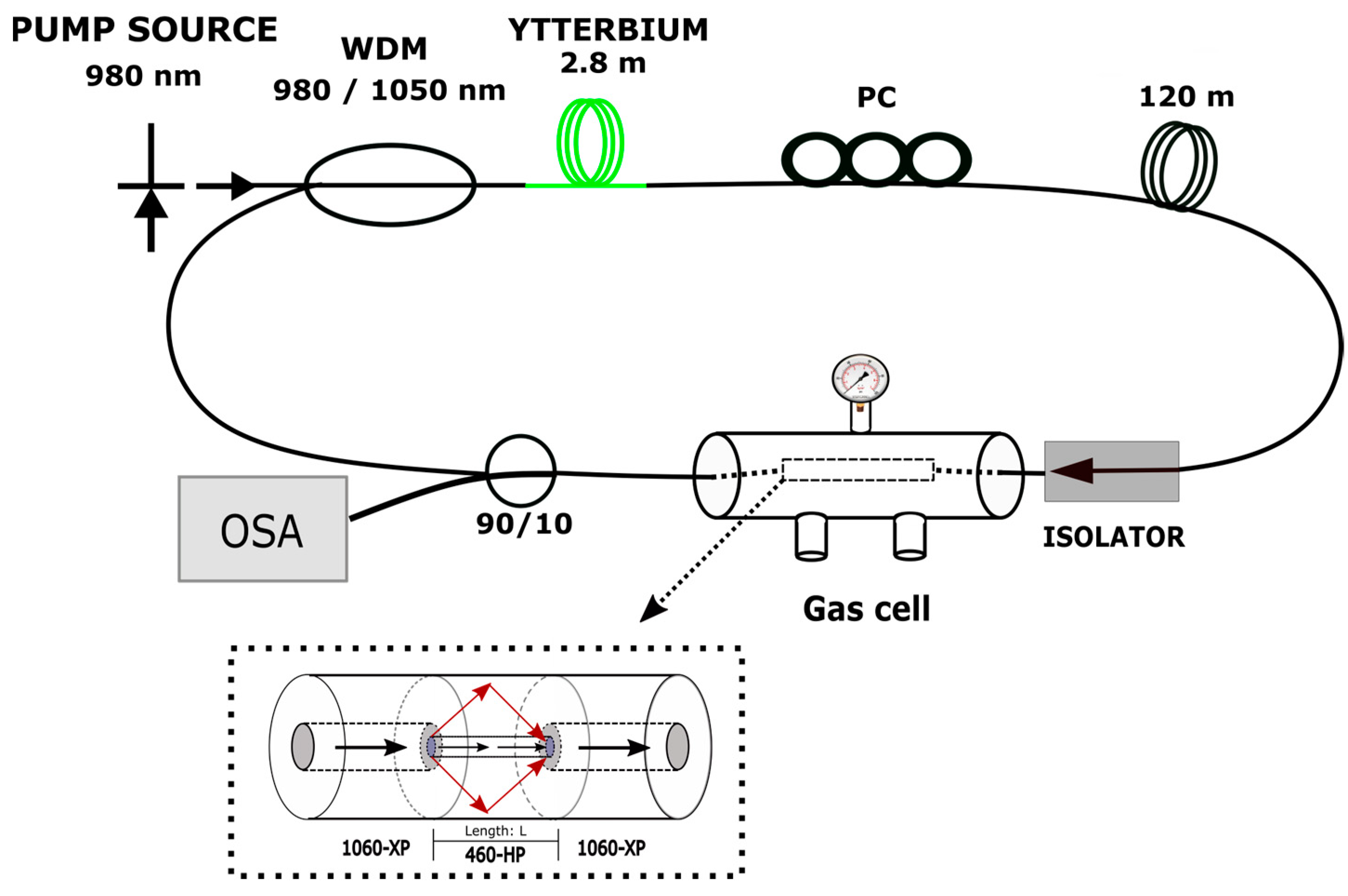
| Items | SMF | TCF |
|---|---|---|
| Core diameter (μm) | 5.8 | 2.5 |
| Cladding diameter (μm) | 125 | 125 |
| Refractive index of core | 1.4512 | 1.4505 |
| Refractive index of cladding | 1.447 | 1.447 |
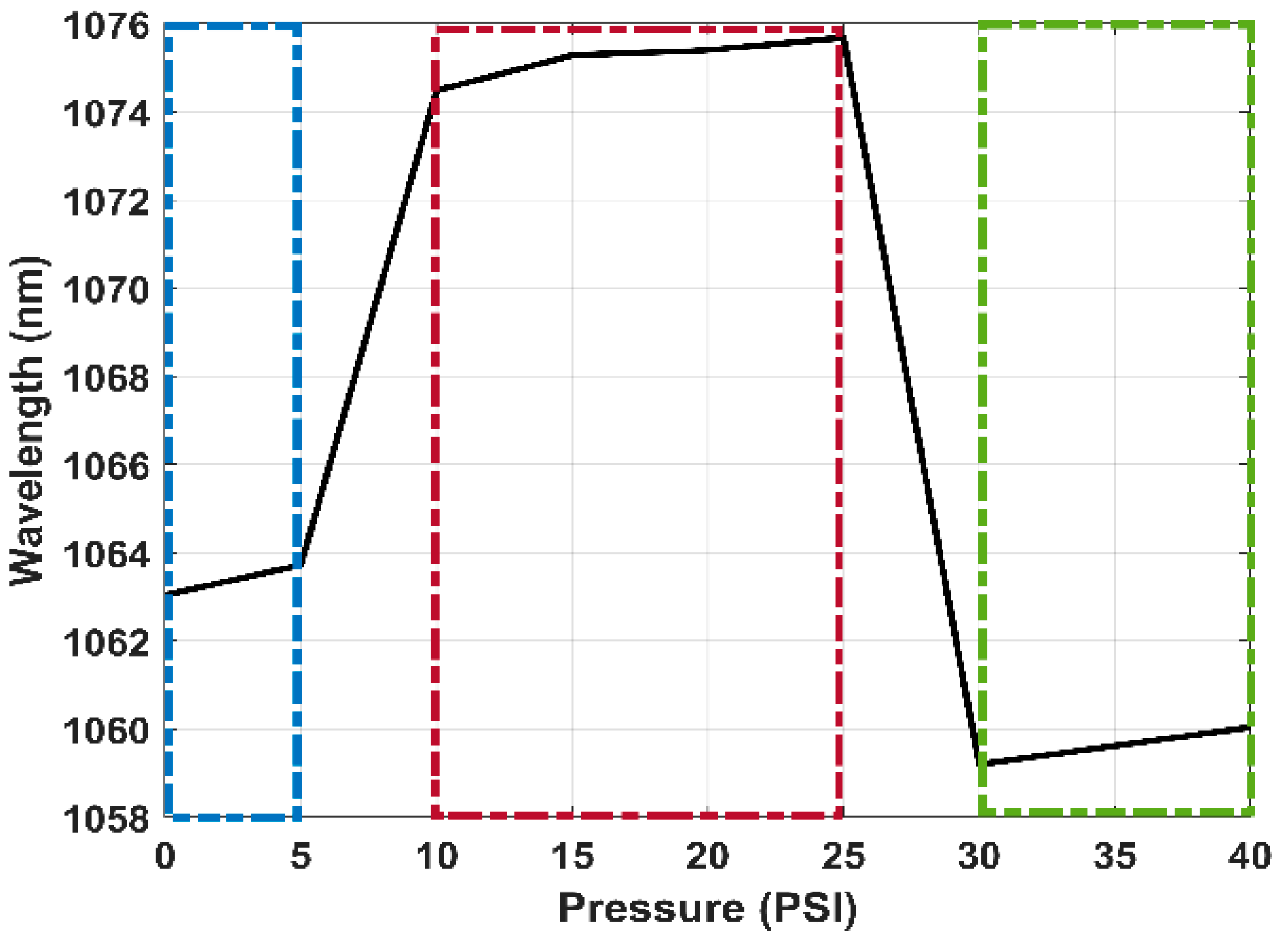
 REF REF | λ1 = 1063.04 nm |
 5 PSI 5 PSI | λ2 = 1063.72 nm |
 10 PSI 10 PSI | λ3 = 1074.48 nm |
 15 PSI 15 PSI | λ4 = 1075.28 nm |
 20 PSI 20 PSI | λ5 = 1075.40 nm |
 25 PSI 25 PSI | λ6 = 1075.68 nm |
 30 PSI 30 PSI | λ7 = 1059.20 nm |
 40 PSI 40 PSI | λ8 = 1060.04 nm |
| Pressure Sensor | Sensitivity |
|---|---|
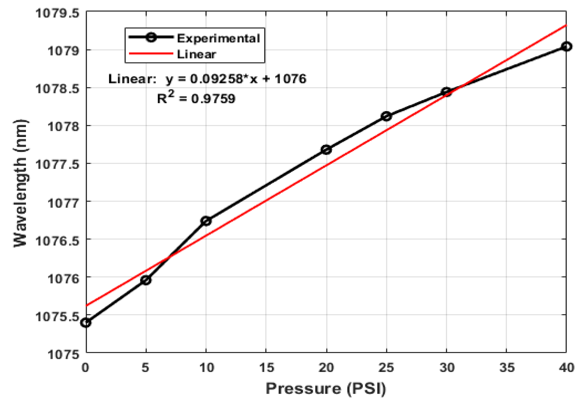
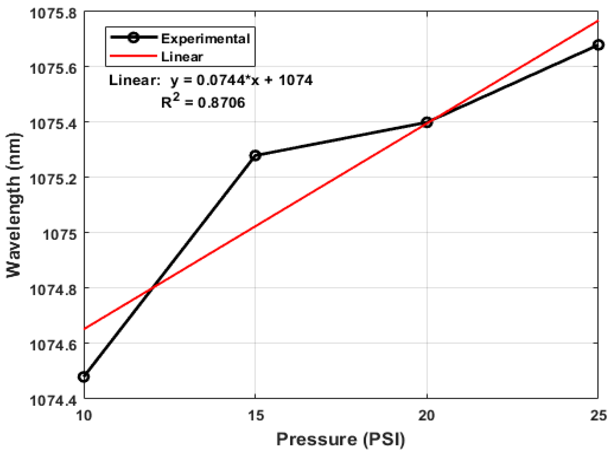
| This work—TCFMI | 0.0925 nm/PSI ≈ 13.23 nm/MPa |
| Twin-core fiber with a micro-channel in one core [29] | −9.6 nm/MPa |
| An MZI based on core-cladding interference with a pair of off-axis twisted distortion points [35] | −5.183 nm/MPa |
| Cascaded fiber MZIs for simultaneous measurement of pressure [40] | 78.553 nm/MPa |
| MZI with a micro-channel across the fiber core [49] | ~8.239 nm/MPa |
Disclaimer/Publisher’s Note: The statements, opinions and data contained in all publications are solely those of the individual author(s) and contributor(s) and not of MDPI and/or the editor(s). MDPI and/or the editor(s) disclaim responsibility for any injury to people or property resulting from any ideas, methods, instructions or products referred to in the content. |
© 2023 by the authors. Licensee MDPI, Basel, Switzerland. This article is an open access article distributed under the terms and conditions of the Creative Commons Attribution (CC BY) license (https://creativecommons.org/licenses/by/4.0/).
Share and Cite
Perez-Guzman, A.; Estudillo-Ayala, J.M.; Jauregui-Vazquez, D.; Hernandez-Garcia, J.C.; Martin-Vela, J.A.; Lozano-Hernandez, T.; Filoteo-Razo, J.D.; Sierra-Hernandez, J.M.; Rojas-Laguna, R. Switchable Fiber Ring Laser Sensor for Air Pressure Based on Mach–Zehnder Interferometer. Appl. Sci. 2023, 13, 12607. https://doi.org/10.3390/app132312607
Perez-Guzman A, Estudillo-Ayala JM, Jauregui-Vazquez D, Hernandez-Garcia JC, Martin-Vela JA, Lozano-Hernandez T, Filoteo-Razo JD, Sierra-Hernandez JM, Rojas-Laguna R. Switchable Fiber Ring Laser Sensor for Air Pressure Based on Mach–Zehnder Interferometer. Applied Sciences. 2023; 13(23):12607. https://doi.org/10.3390/app132312607
Chicago/Turabian StylePerez-Guzman, Adalberto, Julian M. Estudillo-Ayala, Daniel Jauregui-Vazquez, Juan C. Hernandez-Garcia, Javier A. Martin-Vela, Tania Lozano-Hernandez, Jose D. Filoteo-Razo, Juan M. Sierra-Hernandez, and Roberto Rojas-Laguna. 2023. "Switchable Fiber Ring Laser Sensor for Air Pressure Based on Mach–Zehnder Interferometer" Applied Sciences 13, no. 23: 12607. https://doi.org/10.3390/app132312607
APA StylePerez-Guzman, A., Estudillo-Ayala, J. M., Jauregui-Vazquez, D., Hernandez-Garcia, J. C., Martin-Vela, J. A., Lozano-Hernandez, T., Filoteo-Razo, J. D., Sierra-Hernandez, J. M., & Rojas-Laguna, R. (2023). Switchable Fiber Ring Laser Sensor for Air Pressure Based on Mach–Zehnder Interferometer. Applied Sciences, 13(23), 12607. https://doi.org/10.3390/app132312607