Article

Simplified Calculation Method for Active Anti-Floating of Elliptical Basements by Relief Wells

1
School of Civil Engineering and Transportation, South China University of Technology, Guangzhou 510640, China
2
State Key Laboratory of Subtropical Building Science, South China University of Technology, Guangzhou 510640, China
*
Authors to whom correspondence should be addressed.
Appl. Sci. 2023, 13(23), 12647; https://doi.org/10.3390/app132312647
Submission received: 27 October 2023 / Revised: 19 November 2023 / Accepted: 23 November 2023 / Published: 24 November 2023
(This article belongs to the Special Issue Advanced Research on Tunnel Slope Stability and Land Subsidence)

Abstract

:
Currently, there are two main types of anti-floating methods for underground structures; one is the passive anti-floating method represented by anti-draft piles, the other is the active anti-floating method which focuses on interceptor-discharge pressure-reducing (IDPR). In the design of an IDPR anti-floating system, the relief well system situated within the cut-off wall serves as the primary drainage channel. The determination of the seepage field distribution within the multi-well system is vital for the overall design. For the seepage field analysis of the IDPR anti-floating multi-well system, currently numerical analysis is usually used, and there is a lack of simplified analysis methods. The simplified analysis methods already available are based on the uniform distribution of wells in circular pits, while the conversion of non-circular pits into circular pits produce large errors, which are not conducive to promoting the use of the method. To address this, we propose a simplified calculation approach suitable for multi-well systems (arbitrary layout) within elliptical pits. The analytical solution of non-uniformly distributed wells in circular pits is deduced through the principle of superposition. Then, the ellipse is mapped into a circle by using conformal mapping. The resistance coefficient method is adopted, and the internal and external seepage fields are connected in series to obtain the total flow rate, as well as the distribution of the seepage field. This is based on the consideration of the permeability of the waterproof curtains and the bypassing seepage. According to the verification of the calculation example, the results of the simplified algorithm are similar to the results of the finite element method, which proves the accuracy of the method; at the same time, when applied to the actual engineering, the obtained calculation results coincide with the measured data, which proves the practicability and reliability of the method. The simplified method can provide an effective way to design an IDPR anti-floating system.

1. Introduction

In recent years, with the development of the city, increasing attention has been paid to the development of underground space, and a series of large-scale, complete functional systems of underground complexes, underground facilities, urban renovation, and new construction areas has emerged. The construction of these super-large and super-deep basements inevitably faces the problem of calculating the flotation resistance of the underground structure and selecting anti-floating measures. Kong Dezhi et al. [1] pointed out that when a sudden high-water level occurs, a single anti-buoyancy measure cannot actively reduce the water load on the underground structure, and the basement will suffer from wall cracking and floor arching. Wu Yongxia et al. [2] investigated the risk of impact instability of the structure caused by the buoyancy force of groundwater due to the increase in head in the pressurized aquifer in the Shanghai area. Sun Weixin et al. [3] conducted a comprehensive study on the design of shield tunnel cover thickness from the aspects of working surface and anti-buoyancy stability. Li Yang et al. [4] introduced the failure reasons and laws of anti-buoyancy structure through engineering examples of anti-buoyancy accidents. Zheng Yuchao et al. [5] ensured that the large air shafts between the Olympic Sports Centre Station and the Century Avenue Station of Lanzhou Metro Line No. 1 were fitted with anti-float safety devices. The traditional anti-floating measures for underground structures mainly use anti-draft piles or anti-floating anchors, which provide a tensile force to resist the water load acting on the structural base plate. I.H.Wong [6] discussed various methods of passive flotation resistance and explained the conditions applicable to each method. Zhou Tonghe et al. [7] designed a composite pile with a lower expanded section applicable to engineering flotation resistance, analyzed the mechanism of its resistance to pull-out, and proposed a theoretical model of single pile pull-out capacity and calculation parameters for this type of pile. Zhang Minxia et al. [8] conducted field pile pull-out tests of bored and grouted piles and proposed an MMF growth curve model that accurately describes the pull-out load-displacement curve of pull-out resistant piles and predicts the ultimate capacity of piles for underground engineering. Jia Jinqing et al. [9] investigated the shear stress distribution of the anchor in geotechnical soil through destructive tests of pull-out anchors, and pointed out that increasing the length of the anchor has a limited effect on the shear stress of the anchor in the geotechnical soil, while increasing the length of the anchor has only a limited effect on improving its bearing capacity. However, there exists an alternative to this passive ‘resistance’ based approach—an active ‘drainage’ based approach to decompression and flotation [10,11]. In this method, the design water level is lowered and the water load on the bottom of the structure is reduced by installing a hydrophobic layer, a drainage ditch, a relief well below the bottom of the structure or a drainage corridor around the structure to drain the water. By reducing or eliminating the water load, most (or all) of the anti-draft piles or anti-floating anchors can be omitted, and the thickness and reinforcement of the floor slab can be reduced, while the drainage water from the system can be used for other purposes. This is sufficient to offset the cost of long-term pumping. Therefore, compared to conventional passive anti-floating, active drainage relief anti-floating has great economic advantages [12,13,14,15,16,17].
The design of the IDPR anti-floating system primarily addresses four crucial issues: the arrangement of drainage structures, water discharge, pressure distribution on the bottom plate, and environmental impact. To tackle these challenges, the seepage field is divided into inner and outer sections, with the cut-off wall serving as the boundary. The total flow rate is consistent on both sides and is then unified appropriately at the cut-off wall. The calculation of the seepage field on the outer side is relatively straightforward, with the focus being on the inner measurement of the seepage field [18,19]. Currently, numerical methods are typically employed for analysis, and there is a noticeable absence of practical simplified calculation methodologies.
The fundamental concept of simplified calculation for IDPR anti-floating primarily involves three stages. First, the pressure reduction target, which is the average anti-floating water level within the basement floor, is established. The determination of this water level should factor in the characteristics of the structure and the site, the environmental impact of the drainage, the durability of the drainage structure, as well as the volume of the drainage, among other elements. Once the water level is set, the active anti-flooding structure can be designed. In the simplified calculation approach presented in this paper, the anti-floating water level is treated as a known input parameter.
Next is the calculation of the drainage volume. In the simplified calculation of a multi-well system, the superposition principle is commonly used. When there is no impermeable boundary, the drawdown at any point in the multi-well system is the sum of the drawdowns caused by each well at that point [20,21]. Based on the principle of superposition, Mao [22] proposed a method to solve the water depth drop at any point in a pressurized and unpressurized multi-well system under arbitrary arrangement: the group of wells is virtualized as a “big well” and the “big well formula” is used for calculation. The water depth and flow rate can be obtained when the group of wells is approximately circularly distributed. However, in an IDPR environment with cut-off wall to intercept seepage, the big well formula is no longer applicable. In addition, Wu [23] proposed the mirror superposition method to solve the seepage field of a pit with a completely watertight cut-off wall boundary. In fact, the cut-off wall of the pit is not a completely water-insulated boundary, and there is both bypass seepage and through seepage. Wang [24] used the conformal transformation method to find the head and flow in the case of bypass seepage when the thickness of the cut-off wall is taken into account. Hu [25] carried out both approximate calculations and numerical simulations for comparative verification of the mirror superposition method in the case of permeability. However, the above studies did not consider the working conditions of relief wells. Under the condition of cut-off wall, the arrangement of relief wells mainly affects the pressure distribution on the inner side of the cut-off wall, while the influence on the flow rate on the outer side of the cut-off wall is smaller, so the inner and outer seepage flow fields can be decoupled, which provides the feasibility for simplifying the proposed calculation method. For seepage calculations in multi-well systems with the presence of a cut-off wall, a coefficient of resistance method is used which takes the cut-off wall into account; This method was proposed by P.P.Чyгaeв [26] in 1957 on the basis of the theory of Pavlovsky’s segmentation method and the theory of Numeroff’s calculations of rapidly changing seepage zones, and is an approximation of constant seepage in the non-rocky foundations of a lock and dam. It can be used to determine seepage elements at various points in a seepage zone, including the seepage pressure, seepage gradient, and seepage flow rate. Zhu et al. [18] obtained the discharge by solving the seepage field on the inside of the cut-off wall by solving the resistance coefficient. Luo et al. [27] proposed a new computational model to simplify the calculation of water inflow in pits with impermeable walls based on the concept of segmental resistance coefficients under the assumption of two-dimensional seepage in the profile, and gave the formula of segmental resistance coefficients. This is highly accurate and can be used for both watered and unwatered, confined and unconfined, and single-layer and double-layer systems. Mei et al. [28] proposed a simplified method for solving the seepage problem (including wall leakage and wall bypass) in weakly permeable layers by using the solutions of two types of models, namely wall leakage only and wall bypass only, when the effects of permeability and thickness of impermeable walls are considered simultaneously.
Lastly, the outlet height of the drainage structure, its arrangement, and the pressure distribution beneath the basement slab are determined. Various drainage structures such as relief wells, drainage corridors, ditches, etc., are considered in the drainage relief and anti-floating analysis and calculation. The first two steps are consistent across these structures, and mature calculation methods are desired. The primary distinction lies in the final step, which also presents the main challenge in the simplified analysis of IDPR anti-floating. This paper focuses on the calculation and analysis for the relief well. Zhu et al. [18] derived the head distribution of a uniformly distributed multi-well system inside a circular pit, assuming a constant head on the inner boundary of the cut-off wall. However, in practical engineering, the wells within the pit are often unevenly distributed and most have irregular shapes. These need to be mapped into a circle following the Schwarz–Christoffel transform in complex function theory, a process that is quite intricate [29,30,31].
In light of this, based on the conformal mapping method from an ellipse to a unit circle, we propose a simpler and more universally applicable simplified algorithm. This algorithm is designed for the IDPR anti-floating design of elliptical pits under arbitrary well deployment conditions.

2. Simplified Calculation of Multi-Well System for Elliptical Pit

2.1. Basic Assumptions of Simplified Calculations

  • Owing to the function of the cut-off wall, the water inflow of drainage relief depends on the average water level difference between the inside and outside of the pit post-relief and is independent of the specific arrangement of the relief well. Hence, the seepage field is divided into two sections—inside and outside the pit by the cut-off wall. This paper simplifies the calculation method by treating these two parts separately, first calculating the internal seepage field. Subsequently, the pit is equated into a circle based on the area [18], and the equivalent internal seepage field is solved in series with the external seepage field.
  • The seepage field on the inner side of the cut-off wall is pressurized.
  • The primary aquifer layers outside the cut-off wall are categorized into two scenarios: the pressure-bearing mode and the submerged mode. In cases where there are multiple layers of highly permeable strata with negligible variations in permeability coefficients, equivalent permeability coefficients can be employed.
  • The material of each soil layer and cut-off wall is homogeneous and isotropic [32].
  • The inner edge line of the cut-off wall is an equal head line.

2.2. Seepage Field Inside a Circular Pit

For the simplified calculation of unevenly distributed wells in non-circular pits, the first step is to find the analytical solution of the seepage field of unevenly distributed wells in circular pits and then to map it to the non-circle by means of a conformal transformation.
In order to obtain the seepage field on the inside of the cut-off wall of a circular pit, this paper adopts the conformal transformation [33,34] to solve the potential function at any point in the pit. First, a pumping well M 1 with a distance e from the center of the circle and a flow rate q is placed in a circular pit with a radius R . As shown in Figure 1, its coordinates are given as the following:
z = x 1 + i y 1
Next, an injection well M 1 with the same flow rate is placed symmetrically around the circumference of well M 1 ; the inverse mapping of well M 1 gives well M 2 , i.e.,:
z 2 / R = R / z 1
since well M 1 is symmetric with well M 2 about the real axis, the coordinates of well M 1 are obtained:
z 2 ¯ = R 2 / z 1 ¯
then the potential function between well M 1 and well M 1 is calculated as follows:
ω = q 2 π ln ( z z 1 z R 2 / z 1 ¯ ) + C
since in the IDPR conditions, the point on the cut-off wall is taken for the zero point of the potential function, that is, when z = R , the point on the cut-off wall potential function ω = 0 . At this time, the characteristic point is taken on the circumference of z = R and with substitution into the above equation, the following solution is obtained:
C = ln ( R / z 1 )
According to the principle of well superposition, in the case of mutual interference between several relief wells on the site, the potential function at any point within the site is equal to the superposition of the potential functions of several relief wells at that point. Therefore, by the principle of superposition, the potential functions of n relief wells within the circular pit cut-off wall, sorted as i = 1, 2, 3, …, with coordinates ω w i , are superposed to obtain the potential function of the circular pit multi-well system for a cut-off wall at any point ω on the inside of the curtain, as shown below:
φ = i = 1 n q i 2 π ln ( Ξ Ξ w i Ξ R 2 / Ξ w i ¯ R Ξ w i )

2.3. Ellipse to Circle Mapping

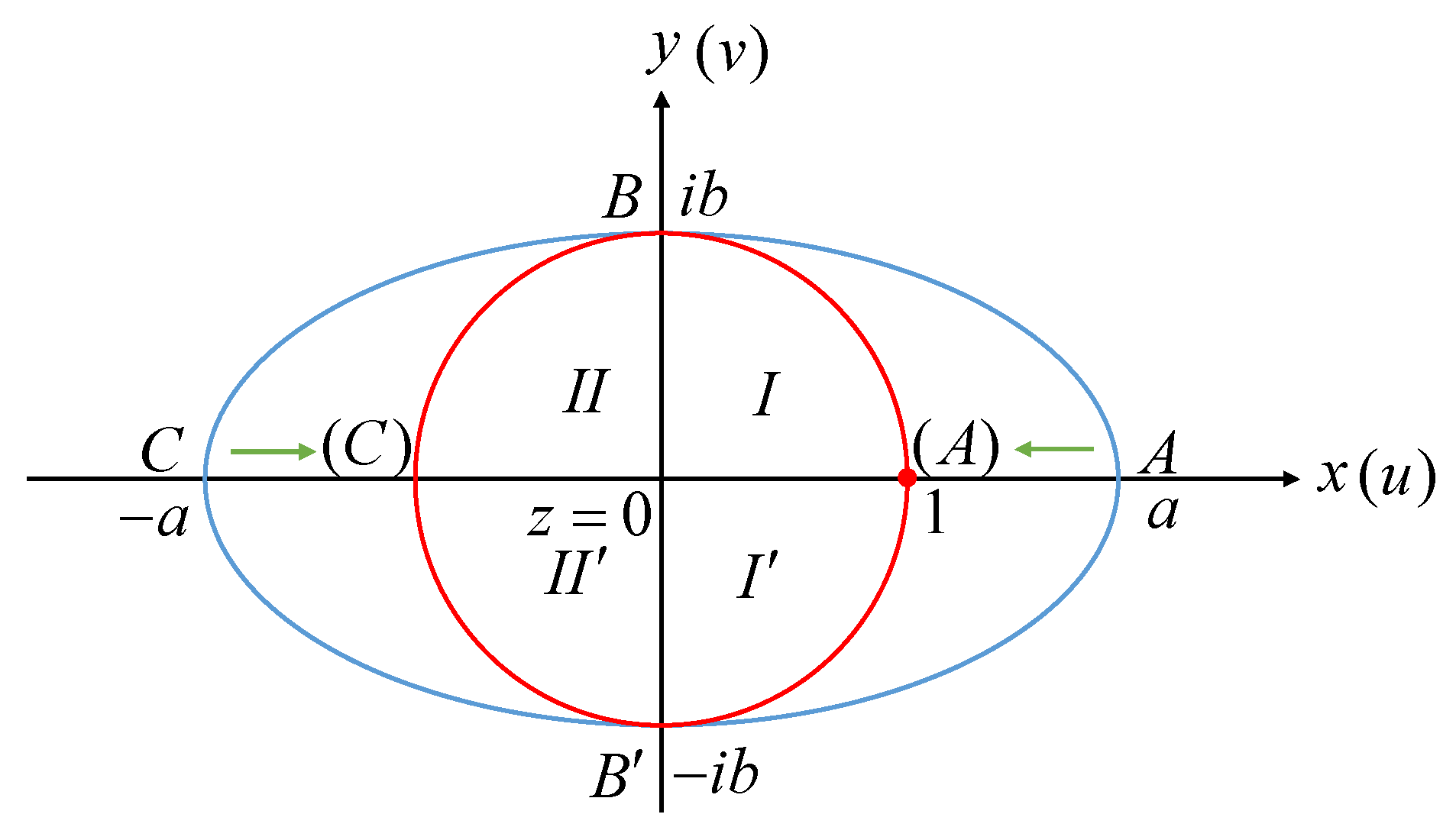
Let the length of the semi-long axis of the ellipse be a, the length of the semi-short axis be b , and ( z = x + y i ) be the coordinates of the points in the plane inside the ellipse. The conformal mapping transformation from ellipse to unit circle is then as follows [34]:
Ξ = k s n ( 2 K π arcsin z a 2 b 2 )
The transformation of an ellipse into a unit circle by the above conformal mapping is shown in Figure 2:
where the parameter k in the elliptic function and the elliptic integral K of the first type are calculated as follows [35]:
k = 2 q 1 4 + 2 q 9 4 + 2 q 25 4 + 1 + 2 q + 2 q 4 + 2 q 9 + 2
K = 0 π / 2 d t 1 k 2 sin 2 t = F ( k , π 2 )
q = ( a b ) ( a + b ) 2
For elliptic functions, the calculation of each function is shown below:
s n   u = m 1 4 θ 1 ( z 0 , q ) θ 4 ( z 0 , q )
where u = 2 K z 0 / π ; m = k 2 , and
θ 1 ( z 0 , q ) = 2 n = 0 ( 1 ) n q ( n + 1 2 ) 2 sin n + 1 2 2 z 0
θ 4 ( z 0 , q ) = 1 + 2 n = 1 ( 1 ) n q n 2 cos ( 2 n z 0 )
First, the coordinates of the elliptical pit ( z = x + y i ) are conformally mapped by the above equation. Second, the equivalent coordinates Ξ after the transformation are substituted into Equation (6) to calculate the potential function of the seepage field inside the circular pit cut-off wall. If there are n wells, there are n equations, and the n flow rates q i are taken as a 1 × n vector x to be solved, and the n equations on the right side of the equations are taken as the n×n matrix A. The n water heads φ on the left side of the equation are used as a n × n vector b. Finally, the matrix equation A x = b is solved using the linalg.solve command in the numpy library in Python to obtain the vector x. The water discharge from each individual well under the water head inside the target pit cut-off wall, and then the seepage field inside the cut-off wall can be obtained by superimposing the seepage field of each individual well distribution.
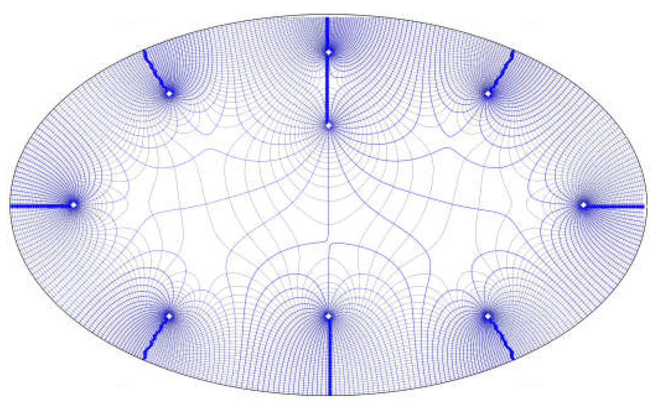
Figure 3 shows the seepage field flow network inside the pit waterproof curtain of an elliptical pit under a non-uniformly arranged relief well, where the blue line is the seepage field flow line and the black line is the seepage field equipotential line.
After obtaining the seepage field distribution inside the cut-off wall of the target pit, the equivalent radius of the elliptical pit is found according to the area equivalent to the circular pit by R d = ( a × b × π ) / π = a b .Then the seepage field inside and outside the pit cut-off wall is solved in series by the resistance coefficient method. Finally the total flow and head of the target pit is obtained.

2.4. Inside-Outside Seepage Field Solved in Series

After obtaining the analytical solution of the inner seepage field, the resistance coefficient method can be used to solve the seepage field of the inner and outer sides of the pit in series using the fsolve module of the scipy library in Python. The resistance coefficient method has three resistance coefficients: ξ 1 , ξ 2 , ξ 3 , can be obtained through the solution of these three coefficients of the total flow Q , so as to calculate the seepage field distribution of the pit under the system of multiple wells, for the underground structure of the interception of the IDPR anti-floating system to provide a basis for design. Depending on the stratigraphic environment in which the pit is located, the calculations can be divided into the pressure-bearing mode and the submerged mode. As shown in Figure 4, the outer head is H d , the inner head is H R , the thickness of the cut-off wall is d , the permeability coefficient is K w , the head at the edge of the affected area is H 0 , the permeability coefficient of the weakly permeable layer at the bottom of the waterproof curtain is K 1 , the thickness is D , the thickness of the outer side is T 1 , the thickness of the inner side is T 2 , and the water level of the relief well is h w . In Figure 4a, K 0 and T 0 are the permeability coefficient and thickness of the pressure-bearing highly permeable layer on the outside of the cut-off wall, and K and T are the permeability coefficient and thickness of the pressure-bearing highly permeable layer on the inside of the cut-off wall. In Figure 4b, K 0 and T 0 are the permeability coefficients and thicknesses of the submerged layer on the outside of the cut-off wall, and K and T are the permeability coefficients and thicknesses of the hydrophobic layer on the inside of the cut-off wall. The specific calculation procedure can be found in the literature [18], only the main formulae are given here.
In pressure-bearing mode, the main aquifer outside the pit cut-off wall is the pressurized soil layer. Among them, the thickness of the relatively highly permeable layer is the thickness of the pressurized highly permeable layer on the outside of the cut-off wall, i.e., T q = T 0 , the permeability coefficient is K 0 , and ξ 1 is the external seepage resistance coefficient, at which time there is the following [23]:
H 0 H d = Q K 0 ξ 1 ξ 1 = 1 2 π T 0 ln R 0 R d
If in submerged mode, then
T 0 = ( h 0 h d ) / 2 h 0 = H 0 z 0 h d = H d z 0
depending on the main aquifer outside the pit cut-off wall, the total flow rate of the seepage field outside the pit cut-off wall can be obtained from the given site head by selecting the above formulae for calculating the seepage field outside the pit cut-off wall in pressure-bearing or submerged mode.
The next step is to calculate the seepage field at the cut-off wall. In pressure-bearing mode, the thickness of the relatively highly permeable layer at this point is T q = ( T 0 / 2 + T / 2 ) and the permeable part of the wall is calculated as follows:
Q 1 = ( H d H R ) 2 π R K w ξ a ξ a = d T 0 / 2 + T / 2
The calculations for the leached part of the wall base are as follows:
Q 2 = ( H d H R ) 2 π R K 1 ξ b ξ b = d D + 2 π T 1 D ln T 1 + D T 1 D + ln T 1 2 D 2 D 2
in submerged mode, the relative high permeability layer thickness is T q = ( H d z 0 + T ) .
The total flow rate at the pit cut-off wall can be found by adding the flow rate of the permeability of the wall and the seepage bypass at the bottom of the wall. ξ s is the resistance coefficient of the permeability and the seepage bypass, i.e., the following:
H d H R = Q 2 π R ξ s ξ s = ξ a ξ b K w ξ b + K 1 ξ a
Finally, the seepage field on the inner side of the cut-off wall can be determined as follows: in Equation (7), let φ = H R h w , q = Q / K T , and ξ 2 is the internal seepage resistance coefficient, then the seepage on the inner side of the pit cut-off wall is calculated as follows:
H R h w = Q K ξ 2 ξ 2 = 1 2 π T Q i = 1 n Q i ln z z w i z R 2 / z w i ¯ R z w i
Equations (14), (18) and (19) can be added together to give:
H 0 h w = Q ξ 1 K 0 + ξ 2 K + ξ s 2 π R
The above equation can be solved to obtain the total flow rate Q , which can be calculated to obtain the distribution of the seepage field in the pit of the multi-well system under the condition of IDPR anti-floating.

2.5. Processes to Simplify Calculations

Based on the previous discussion, the simplified calculation can be summarized into the following steps.
  • Determine the parameters: first, determine whether the seepage calculation mode of the outside of the cut-off wall is pressure-bearing or submerged; second, determine the seepage parameters of the site, such as the area of influence of the seepage field R 0 , the height of the edge of the area of influence H 0 , the thickness of the gravelly sand layer T 0 , the thickness of the powdery clay layer T 1 , the depth of the relief wells and the thickness of the water-reducing layer T , the thickness of the cut-off wall in the pit d , the permeability coefficients of the highly permeable layer and the water-reducing layer K , the permeability coefficient of the weakly permeable layer K 1 , the permeability coefficient of the highly permeable layer K 2 , the permeability coefficient of the cut-off wall K w , the thickness of the weakly permeable layer at the bottom of the cut-off wall D , and the shape of the pit, etc. Finally, the location of the relief wells, the diameter of the wells r w , and the height of the wellhead h w are adjusted.
  • Simplify an arbitrarily shaped pit to an ellipse according to its area and map it to a unit circle. First, according to the shape of the target pit, which is equivalent to the ellipse that it most closely resembles, the target pit is transformed to a unit circle by conformal mapping.
  • Internal seepage field calculation. After obtaining the equivalent coordinates of the pit through conformal transformation, assuming the water head height on the inner side of the cut-off wall and the wellhead elevation, let φ = H R h w .Together with the transformed equivalent coordinates, substitute them into Equation (6) for calculating the potential function of the internal seepage field in the circular pit with a curtain. This will yield a system of equations A x = B , where A is an n × n matrix representing wellbore information, and B is a 1 × n matrix representing the difference in water head. Solve this system of equations to obtain the 1 × n matrix x, which represents the discharge flow rate of each well under the assumed water head conditions, i.e., the ratio of discharge flow rates between wells. Finally, the distribution of the seepage field inside the target pit’s curtain under the assumed water head can be obtained by the superposition principle.
  • Serial solution of seepage fields on the inner and outer sides. The elliptical pit is transformed into an equivalent circular pit based on the equal area, obtaining the equivalent radius R d of the pit. By using the resistance coefficient method, the assumed water head in step 2 is related to the actual water head at the site. The resistance coefficient formulas for internal seepage Equation (19), external seepage Equation (14), and seepage and bypass resistance at the cut-off wall Equation (18) are connected in series using the resistance coefficient method formula Equation (20). Finally, the distribution of actual water head heights at the site, as well as the total flow rate and the actual discharge of each well, are solved.
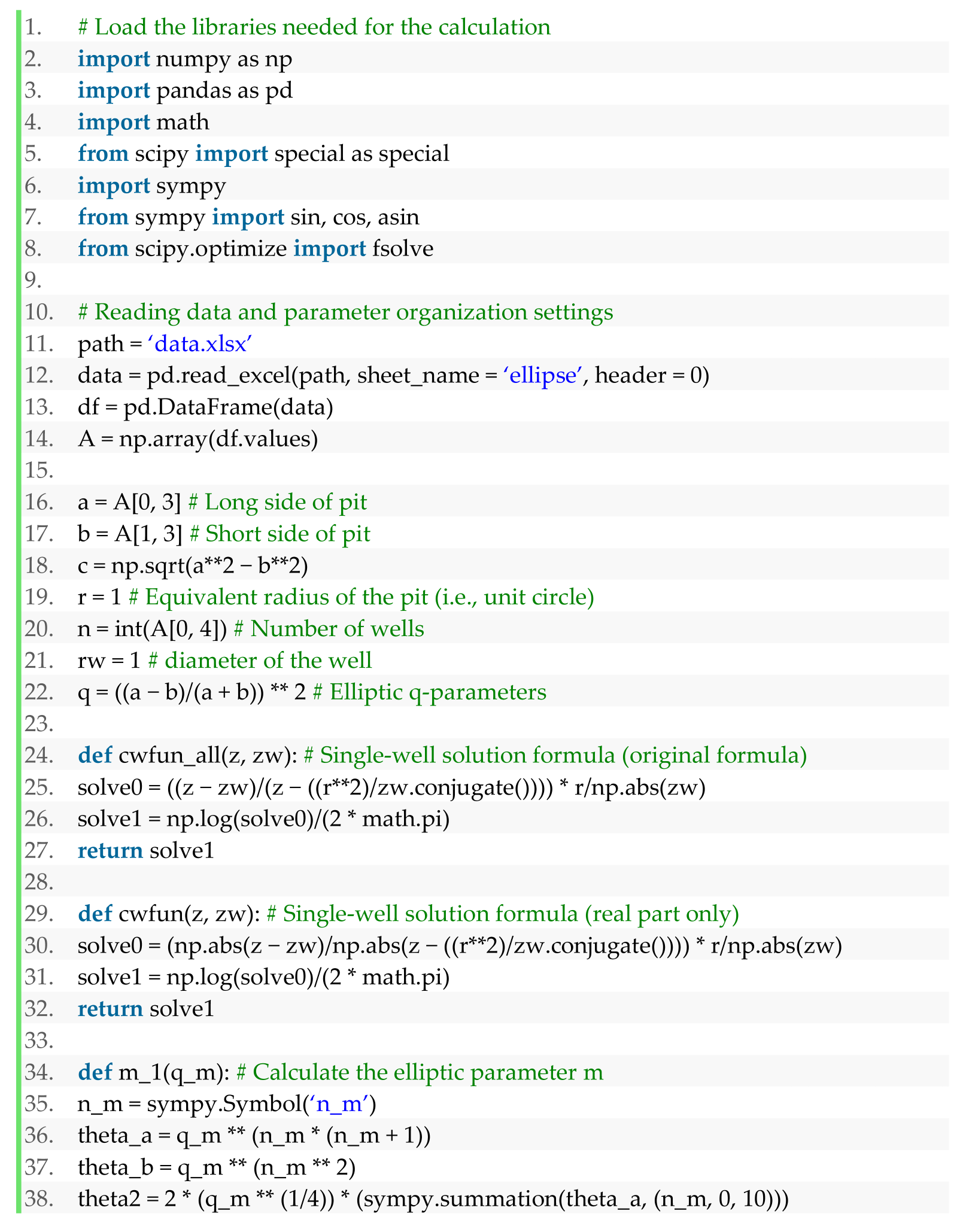
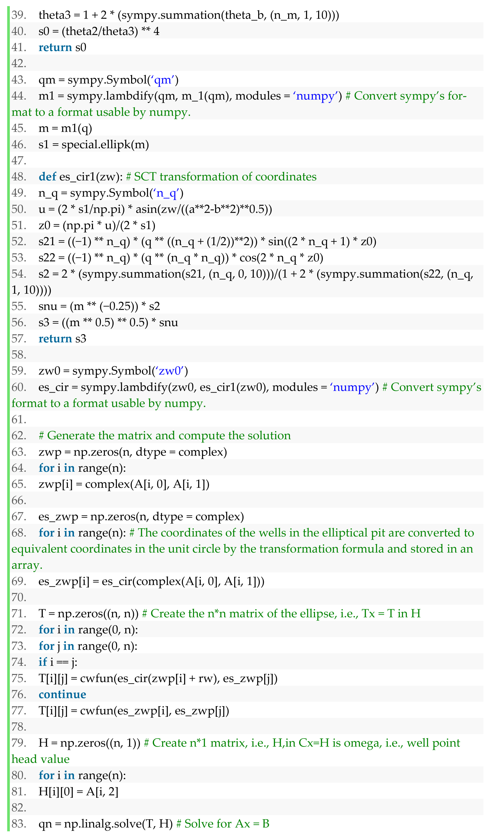
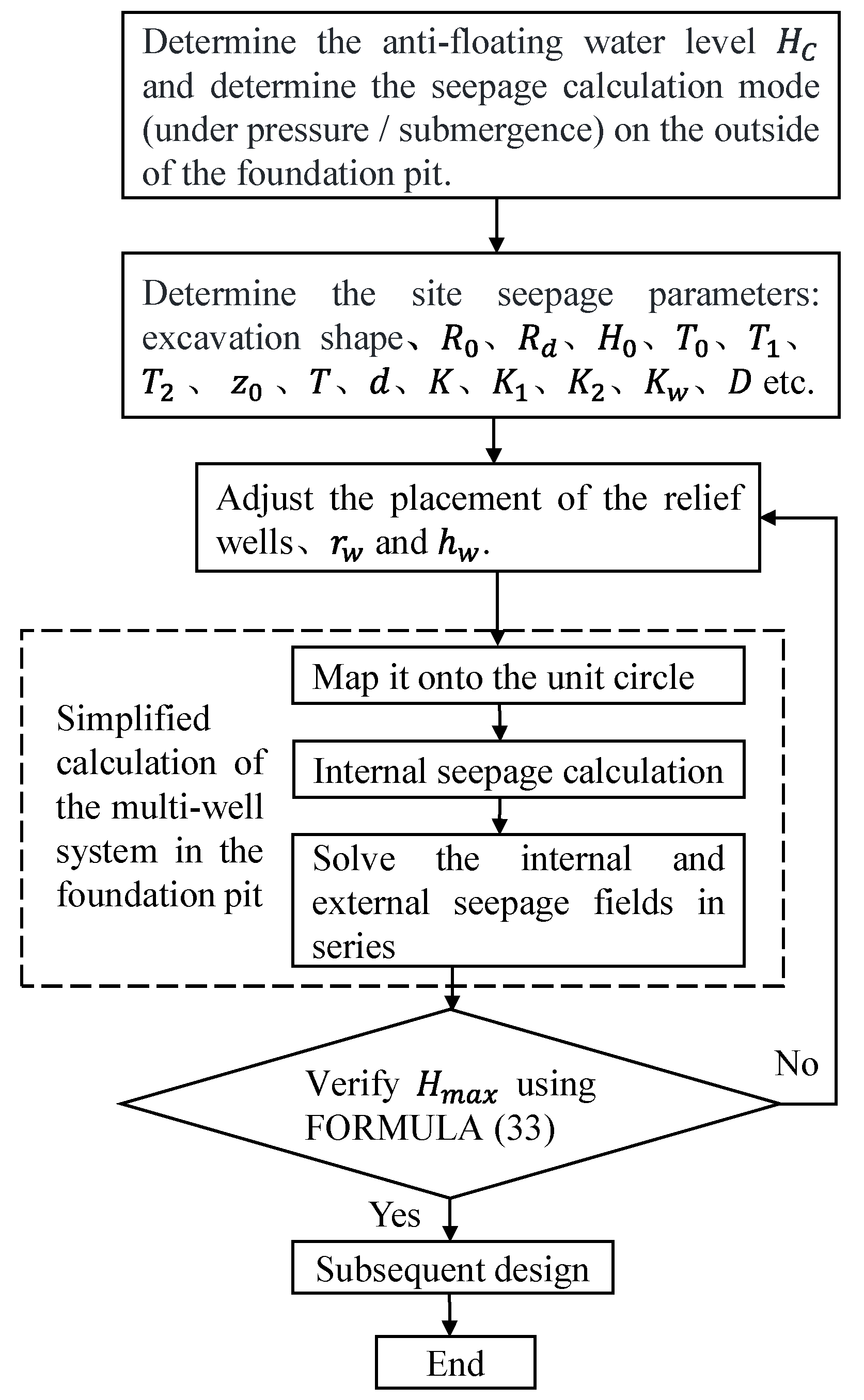
In summary, the application process of this simplified calculation in the design of IDPR anti-floating is shown in Figure 5. See Appendix A for details of calculation codes.

3. Algorithm Validation

3.1. Arithmetic Parameters for Simplified Calculations

The normal operating program is divided into pressure-bearing and submerged modes with fixed parameters as shown in Table 1. Other parameters for the pressure-bearing and submerged modes are given in Table 2 and Table 3. The 20 relief wells in different shapes of elliptical pits were arranged by three different methods: single-circle homogeneous, double-circle homogeneous, and non-homogeneous, while the distribution of the wells is shown in Figure 6.

3.2. Flow Verification

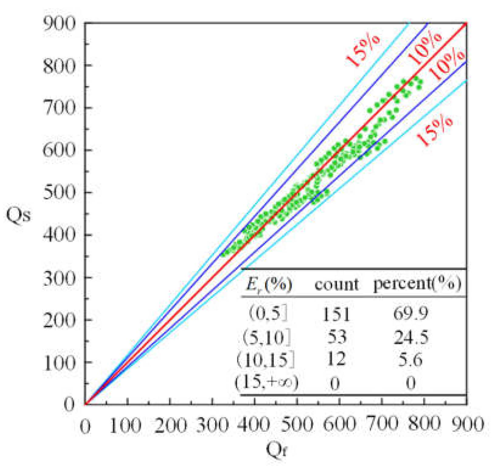
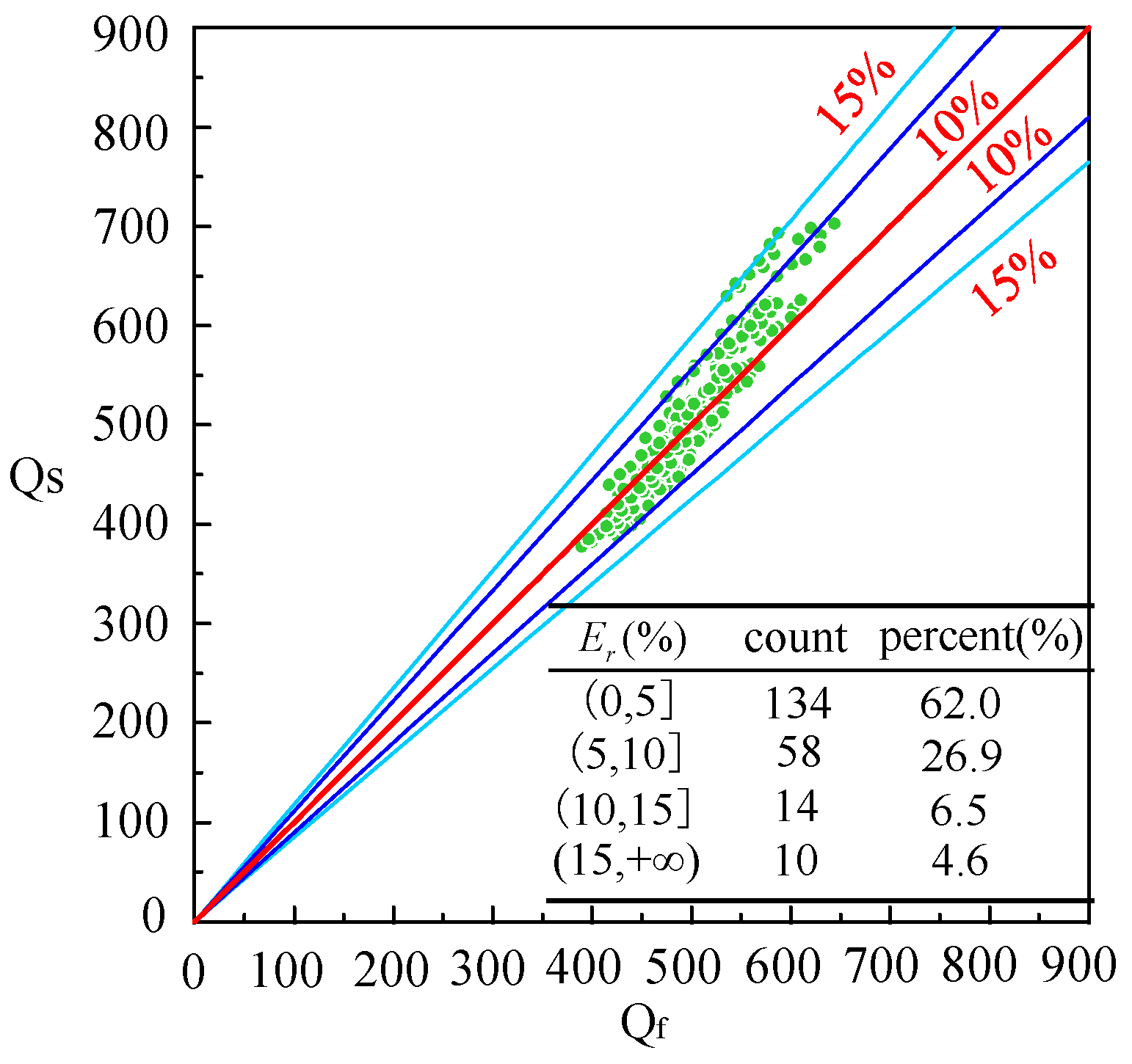
The simplified calculation method and the finite element method were used to calculate the scheme groups in the pressure-bearing mode and the submerged mode, respectively. The simplified calculated total flow Q s of elliptical pits and the total flow Q f of elliptical pits calculated by finite element numerical simulation under different parameters were obtained, and the results of comparison and distribution of the two, with a total of 432 calculation cases.
The distribution of simplified calculation errors for the pressure-bearing mode under different parameter conditions is shown in Figure 7. The majority of the cases in the pressure-bearing mode exhibit errors within 10%, with only a small portion exceeding this threshold. In these cases, the simplified calculation results are generally lower than the finite element calculation results. This is because the circumference of an ellipse is greater than that of a circle with the same area. After the shape transformation, the total length of the cut-off wall in the pit is reduced. Consequently, the seepage around the bottom of the cut-off wall and the permeable flow through the wall are also reduced. As a result, the simplified calculation tends to yield lower results compared to the finite element calculation. However, overall, the accuracy of the simplified calculation for the multi-well system’s seepage field in an elliptical pit under normal operating conditions in the pressure-bearing mode is generally high and meets engineering requirements.
The calculation results for the submerged mode are shown in Figure 8. The majority of the cases exhibit errors within 10%, with only a very small portion exceeding 15%. This indicates that under the condition of IDPR, the simplified calculation results for the seepage field of an elliptical pit in the submerged mode under normal operating conditions are highly accurate. Moreover, most of the simplified calculation examples with errors exceeding 10% tend to overestimate the results. This suggests that the simplified calculation results are relatively conservative compared to the finite element calculation, thereby meeting both engineering and safety requirements.

3.3. Hydraulic Pressure Distribution Verification

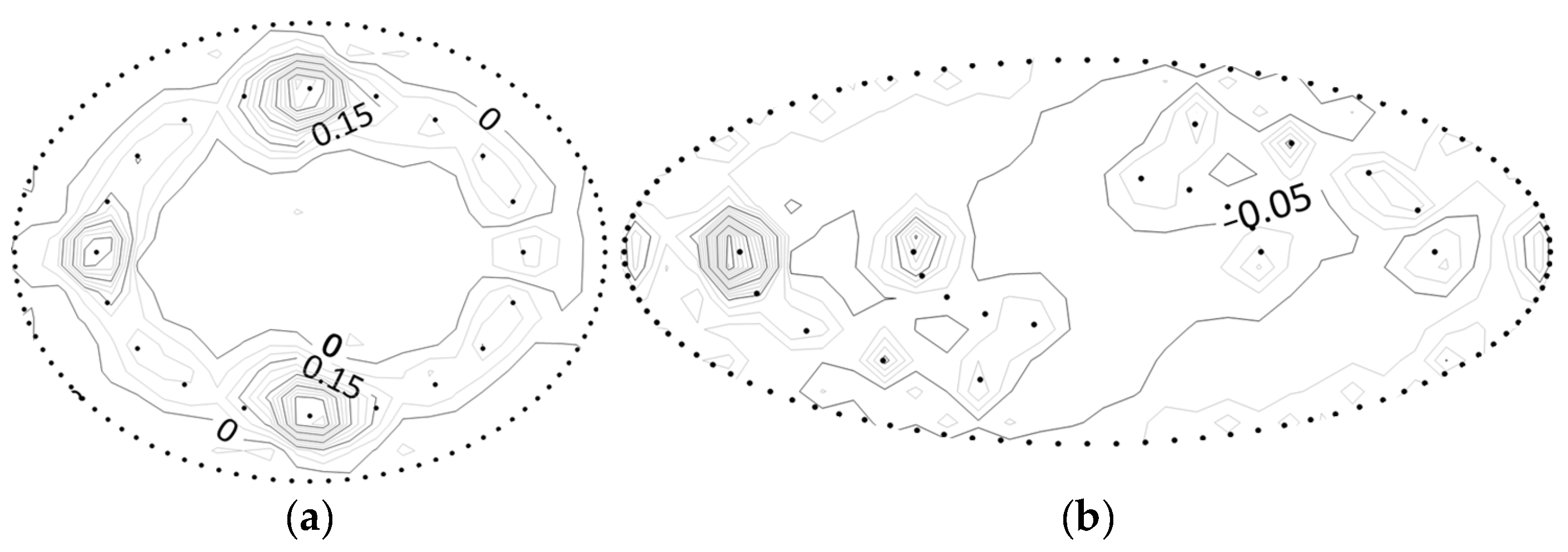
As shown in Figure 9, in the pressure-bearing mode, the overall head error is minimal when the A well layout is used in the elliptical foundation pit with the smallest aspect ratio, while the maximum overall head error occurs when the C well layout is used in the elliptical foundation pit with the largest aspect ratio. This is because the simplified calculations in this paper assume a constant head for the cut-off wall. If the well locations are relatively uniform and there is a large number of wells, the head distribution of the cut-off wall will be relatively uniform, basically consistent with the assumed uniform head. Additionally, when the aspect ratio of the ellipse is small, the head near the cut-off wall is more uniformly affected by the relief wells and is closer to the assumed uniform head, resulting in a smaller overall head error in the calculations. The overall head errors in the numerical examples are relatively small, but there are larger errors in the areas close to the relief wells. This is because the vicinity of the relief wells is treated as a “singular region” in the simplified calculations, leading to larger head errors. However, in the areas farther away from the relief wells, the head errors are all within 10%, and the calculated values are larger than the finite element results, making them relatively safe for construction and generally suitable for engineering applications.
As shown in Figure 10, in the submerged mode, the scenarios and reasons for the maximum and minimum overall head errors are the same as those in the aforementioned pressure-bearing mode. When the head distribution of the cut-off wall is relatively uniform, it is closer to the assumed uniform head, resulting in a smaller overall head error in the calculations. The overall head errors in the numerical examples are relatively small, but there are larger errors in the areas close to the relief wells. However, in the areas farther away from the relief wells, the head errors are all within 10%, and the calculated values are larger than the finite element results, making them relatively safe for construction and generally suitable for engineering applications.

3.4. Error Analysis of a Pit Simplified to an Ellipse

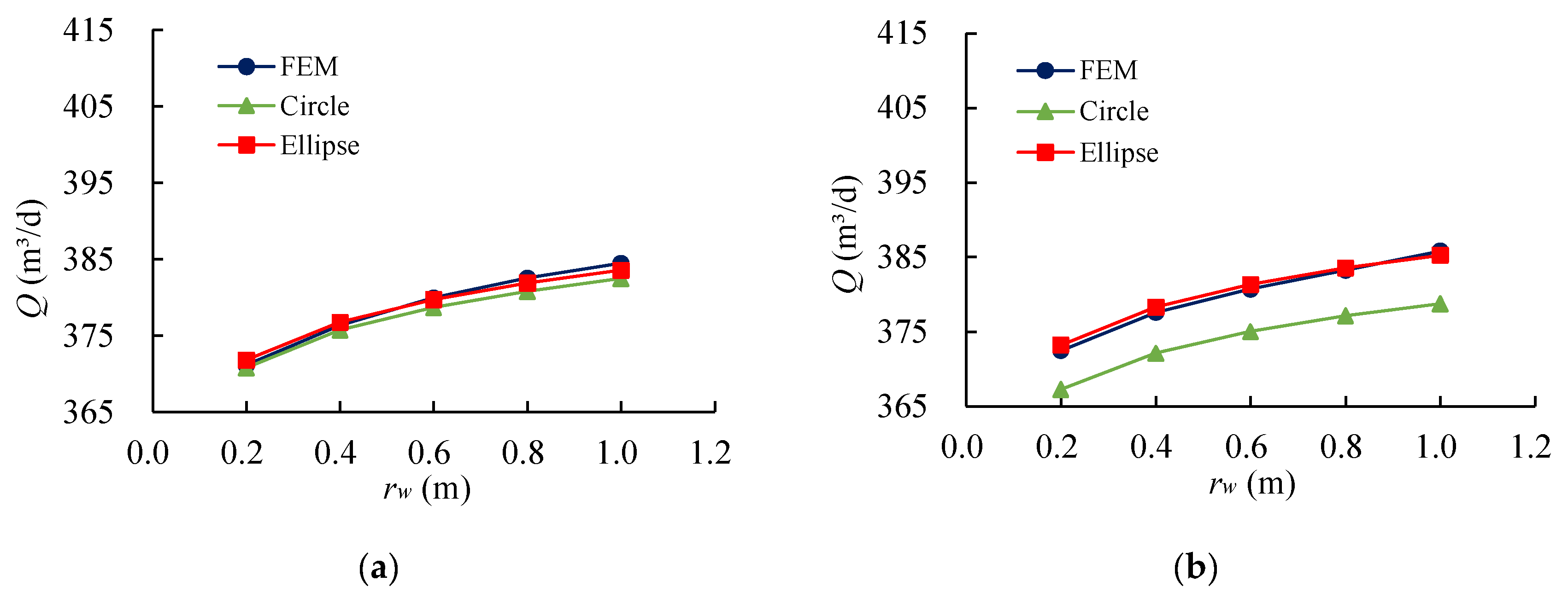
Various simplified calculation methods are used to calculate the pressure-bearing elliptical pit. The elliptical pit model used is the same as the pressure-bearing pit in the elliptical pit example used in the previous section with the same fixed parameters. The elliptical pit has the half-long axis length of a, the half-short axis length of b , the thickness of the strongly permeable layer of T0 = 2 m, the thickness of the weakly permeable layer of T1 = 5 m, the thickness of the hydrophobic layer of T = 0.6 m, the diameter of the borehole rw = 0.5 m, the thickness of the pit cut-off wall d = 1.6 m. The results of this pit calculated by different shapes of simplified calculation methods are shown in Figure 10.
As can be seen from Figure 11, when the length-to-width ratio of the elliptical pit is small in the pressure-bearing mode, the results calculated by the elliptical simplified calculation method are close to those calculated by the circular simplified calculation method and the finite element calculation results with high accuracy. As the aspect ratio of the elliptical pit further increases, the error of the circular simplified calculation method gradually increases, while the elliptical simplified calculation method can maintain a small error.
Similar conclusions were reached for the submerged mode as for the pressure-bearing mode. That is, when the pit is closer to a circle, both simplified calculation methods are more accurate, but as the elliptical aspect ratio increases, the elliptical simplified calculation method is more accurate than the circular simplified calculation method.

4. IDPR Anti-Floating Design and Case Application

4.1. Control Parameters for Anti-Floating Design

In the design of the IDPR anti-floating system, the head value of the bottom plate should be controlled by the following formula in order to ensure the safety of the structure [36]:
H max · κ H c = G + F t A γ w
Among them, H max represents the maximum head beneath the bottom plate. The safety coefficient κ is typically equal to or greater than 1. H c denotes the anti-floating control level. G accounts for the self-weight of the structure. F t represents the buoyancy resistance provided by passive anti-floating measures such as anchors. A corresponds to the area of the structural bottom. γ w signifies the gravitational weight of the groundwater.
After the simplified calculation of the pit, it is judged whether the maximum head of the bottom plate H max meets the design requirements by using the above formula, if not, it must be redesigned. If it meets the requirements, the calculation results are used of the total water flow from the pit Q and the water from a single well Q i to design the pump power, head and drainage pipe, and the maximum head of the site H max is used to check the reinforcement of the bottom plate and the width of the cracks, etc.

4.2. Verification of Actual Engineering Case

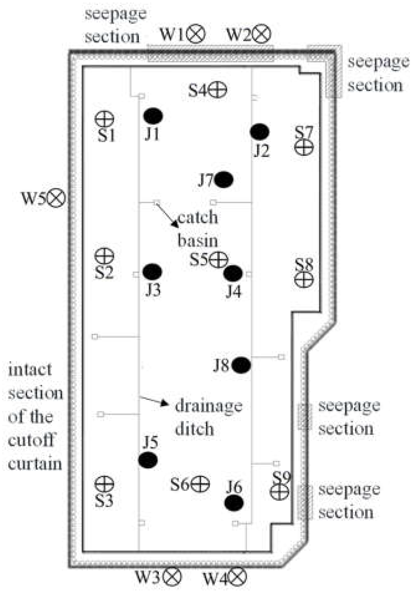
Taking the engineering case in literature [12] as an example, the project is located in the underground car park of a hospital in Huadu District, Guangzhou City, and the distribution of the relief wells is shown in Figure 12, where J1~J8 are the relief wells, S1~S9 are the pressure measuring tubes of the base plate, and W1~W5 are the peripheral water level observation holes.
According to the statistics, the final parameters for each seepage calculation for this case are as follows: influence zone of seepage field R0 = 300 m; the head height at the edge of the impact area is assumed to be H01 = 9.5 m under normal working conditions; H02 = 9.5 m under extreme rainfall conditions; the diameter of the relief well is rw = 1 m; and the well head height is hw = 0.05 m; thickness of gravelly sand layer T0 = 11 m; thickness of powdery clay layer T1 = 18 m; depth of relief well and thickness of hydrophobic layer T = 1.7 m; thickness of cut-off wall d = 0.77 m; permeability coefficient of highly permeable and hydrophobic layer K = 2.2 × 10⁻¹ cm/s; permeability coefficient of weakly permeable layer K1 = 2 × 10⁻⁴ cm/s; permeability coefficient of highly permeable layer K2 = 2.2 × 10⁻¹ cm/s; permeability coefficient of pit cut-off wall Kw = 5 × 10⁻¹ cm/s; thickness of the weakly permeable layer at the bottom of the pit waterproof curtain D = 16 m; number of wells n = 8.
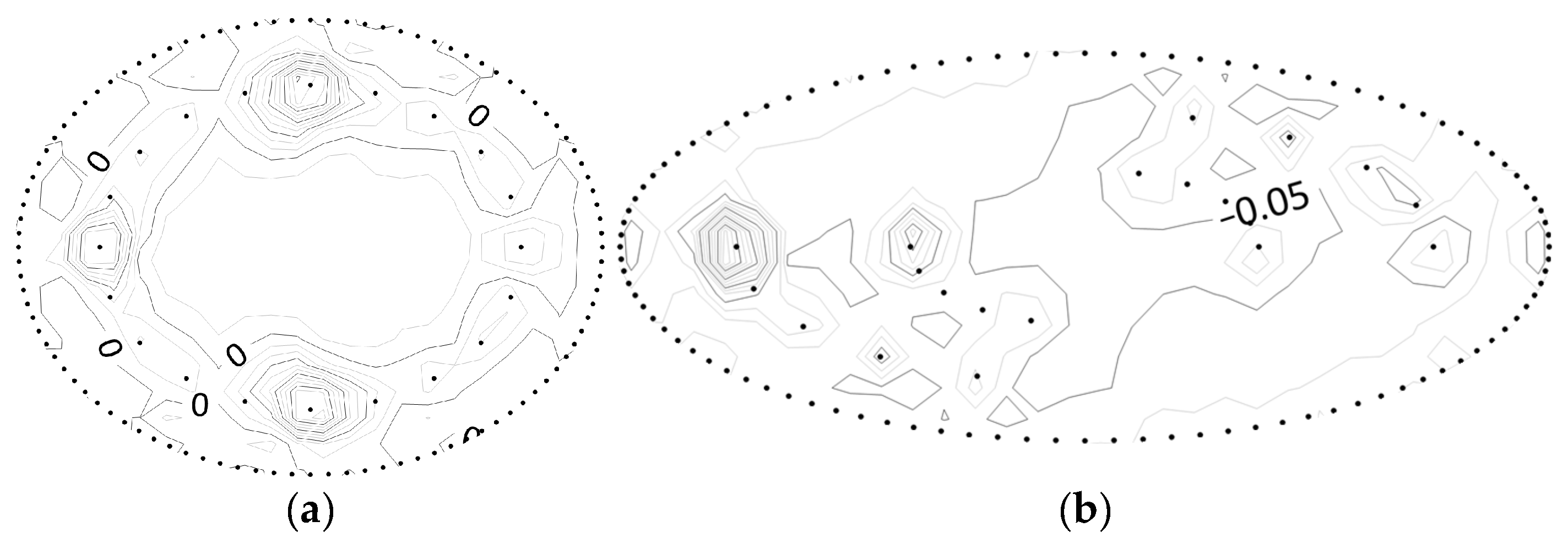
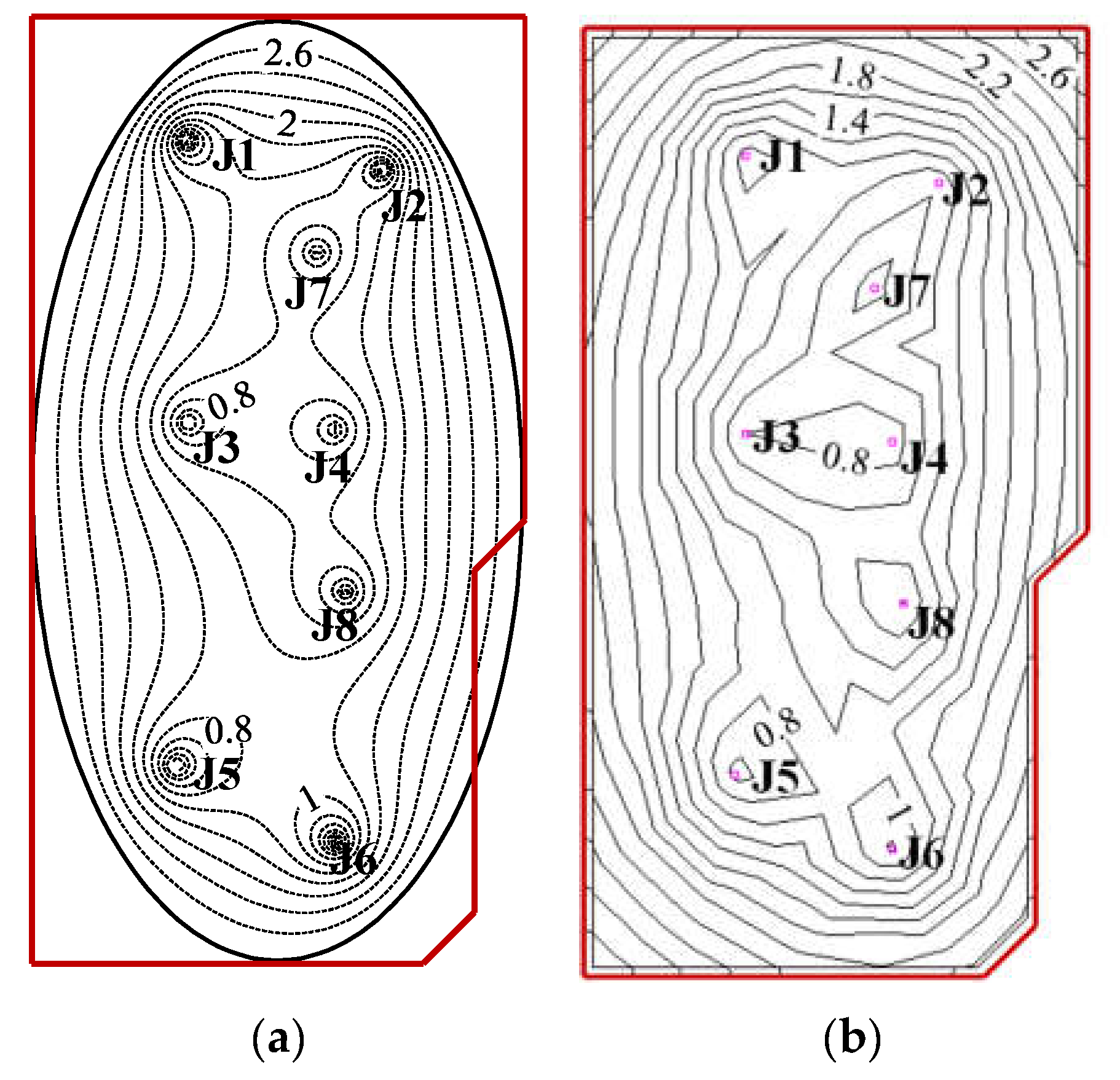
The total flow rate of the site is 1606 m3/d in the final calculation, the total flow rate of the site is 1622 m3/d in the finite element calculation, and the average value of the measured total flow rate is 1563 m3/d. The distribution of the seepage field inside the pit curtain under the different calculation methods is shown in Figure 13, from which it can be seen that the simplified calculation is accurate and can be safely used in the project with high reliability and practicality.

5. Conclusions

Combined with the conformal mapping, a simplified calculation method was proposed for the multi-well system of an elliptical pit under the condition of IDPR anti-floating. This solves the problem whereby the existing calculation method focuses on the circular pit under the condition of uniformly distributed wells; the principle of calculation is clear and easy to understand, and the process is simple. The results of the calculations were compared with those of the finite element calculations to validate the reasonableness of the simplified calculation method. The following conclusions were drawn:
  • For the elliptical pit, it is transformed into a unit circle by conformal mapping, and after obtaining the equivalent coordinates after the transformation, the seepage field of the pit is solved by combining with the resistance coefficient method, so as to obtain the simplified calculation method for the multi-well system of the elliptical pit.
  • By comparing the results of the simplified calculation method with the seepage field distribution obtained from finite element calculations, as well as the total flow rate and head, it is observed that the seepage field distribution inside the pit is nearly identical. This demonstrates the high accuracy of the simplified calculation method for the multi-well system of elliptical pits under IDPR conditions. Furthermore, the simplified calculation method was successfully applied to real-world engineering cases. By comparing the results of the simplified calculation with both the finite element calculations and the actual measured data, the reasonableness and practicality of the simplified calculation method were further validated.
  • This simplified calculation method is suitable for sites with relatively uniform soil thickness and permeability, such as sites with artificial hydrophobic layers, but its accuracy needs to be further improved for sites with large variations in soil distribution.

Author Contributions

Conceptualization, G.L. and F.Y.; methodology, G.L. and F.Y.; software, H.L.; validation, H.C. and H.P.; formal analysis, F.Y.; data curation, F.Y. and H.L.; writing-original draft preparation, F.Y.; writing-review and editing, H.P.; All authors have read and agreed to the published version of the manuscript.

Funding

This research was funded by National Natural Science Foundation of China (Grant No. 51978282, No. 52308343, No. 52308353) and the Guangdong Basic and Applied Basic Research Foundation (Grant No. 2023A1515011571, No. 2023A1515011683, No. 2019A1515110837).

Informed Consent Statement

Not applicable.

Data Availability Statement

The data presented or analyzed in this study are available on request from the corresponding author. The data are not publicly available due to engineering and construction requires confidentiality.

Conflicts of Interest

The authors declare that there are no known conflicts of interest associated with this publication and there has been no significant financial support for this work that could have influenced its outcome.

Appendix A

Calculation codes written in python.
Applsci 13 12647 i001
Applsci 13 12647 i002
Applsci 13 12647 i003

References

  1. Dezhi, K.; Yanan, G.; Hua, Y. Study on the anti-floating water level of the underground structure’s comprehensive anti-floating. Structures 2023, 56, 104921. [Google Scholar] [CrossRef]
  2. Wu, Y.; Yang, T.; Li, P.; Lin, J. Investigation of groundwater withdrawal and recharge affecting underground structures in the Shanghai urban area. Sustainability 2019, 11, 7162. [Google Scholar] [CrossRef]
  3. Sun, W.; Liu, H.; Zhang, W.; Liu, S.; Gao, X. Investigation on overburden thickness considering face and anti-floating stability of shallow shield tunnel. Comput. Geotech. 2023, 160, 105562. [Google Scholar] [CrossRef]
  4. Yang, L.H.; Wang, H.; Han, Z.G. Analysis and reinforcement on the up-floating accident of the basement of a large commercial complex. Appl. Mech. Mater. 2014, 578, 240–243. [Google Scholar] [CrossRef]
  5. Zheng, Y.; Xiong, J.; Liu, T.; Yue, X.; Qiu, J. Performance of a deep excavation in Lanzhou strong permeable sandy gravel strata. Arab. J. Geosci. 2020, 13, 156. [Google Scholar] [CrossRef]
  6. Wong, I.H. Methods of resisting hydrostatic uplift in substructures. Tunn. Undergr. Space Technol. 2001, 16, 77–86. [Google Scholar] [CrossRef]
  7. Zhou, T.; Gao, X.; Guo, Y.; Sun, Y. Design method and experimental study of uplift bearing capacity of the lower enlarged composite pile. Rock Soil Mech. 2019, 40, 3778–3782+3788. [Google Scholar] [CrossRef]
  8. Zhang, M.; Fan, K.; Liao, S.; Xu, P.; Li, J.; Chen, C. Prediction of ultimate antifloating force of bored piles in urban road crossing overpass. Geofluids 2022, 2022, 8170585. [Google Scholar] [CrossRef]
  9. Jia, J.; Song, E. The design and test on anti-floating anchorage of large substructure in coastal region. Chin. J. Geotech. Eng. 2002, 24, 769–771. [Google Scholar] [CrossRef]
  10. Xu, Z.; Lai, Y.; Mei, G. Numerical simulation of water-discharging pressure-relief technology on anti-floating of swimming pools. Chin. J. Geotech. Eng. 2013, 35, 451–455. [Google Scholar]
  11. Yang, B.; Li, Y.; Gan, Q.; Liu, W.; Kong, Q.; Huang, J. Orthogonal analysis of factors affecting the anti-floating effect of draining decompression. J. Chang. River Sci. Res. Inst. 2016, 33, 121. [Google Scholar] [CrossRef]
  12. Zhu, D.; Cao, H.; Luo, G.; Pan, H.; Mei, J. Application of interception and drainage anti-floating system in treatment of uplift accidents. Chin. J. Geotech. Eng. 2018, 40, 1746–1752. [Google Scholar] [CrossRef]
  13. Ling, C.; Dong, J.; Xie, J.; An, X.; Luo, H.; Dong, J. Experimental study on anti-floating model by drainage in underground metro station of the tertiary terrace of Yangtze River in Wuhan. Eng. J. Wuhan Univ. 2023, 56, 1088–1095. [Google Scholar] [CrossRef]
  14. Cao, Y.; Yuan, X.; Zhang, M.; Lu, C.; Su, P.; Zhao, Y. Design and analysis of drainage depressurization and floatation reduction in the basement of a building on a slope. Build. Struct. 2022, 52, 105–110. [Google Scholar] [CrossRef]
  15. Luo, Y.; Chen, J.; Wang, Y.; Shen, P. Anti-floating failure mechanism of underground structures in expansive soil area and application of active anti-floating measures. Hydrogeol. Eng. Geol. 2022, 49, 64–73. [Google Scholar] [CrossRef]
  16. Zhu, D.; Luo, C.; Li, J. Understanding and thinking about “Technical Standard for Building Engineering against Uplift”. Chin. J. Undergr. Space Eng. 2022, 18, 628–634. [Google Scholar]
  17. Li, J.; Zhu, G.; Wang, J.; Zeng, P. Application of active anti-floating in underground structure based on automatic drainage system. In Proceedings of the International Conference on Civil, Architecture and Engineering Management, Taiyuan, China, 16–18 October 2020. [Google Scholar] [CrossRef]
  18. Zhu, D.; Cao, H.; Luo, G.; Pan, H.; Luo, C. Simplified calculation and design method of multi-well system for anti-uplifting based on intercepting and discharging water. Chin. J. Geotech. Eng. 2021, 43, 1986–1993. [Google Scholar] [CrossRef]
  19. Li, Y.; Chen, D.; Liu, X.; Xie, X.; Tong, X.; Zhang, J. Simplified calculation method of decompression dewatering for deep excavation with suspended waterproof curtain. Rock Soil Mech. 2021, 42, 826–832. [Google Scholar] [CrossRef]
  20. Yuan, H.; Zhang, Q. Optimization design and application of dewatering-recharge system in deep excavation. J. Shanghai Jiao Tong Univ. 2013, 47, 1424–1429. [Google Scholar] [CrossRef]
  21. Gao, Y.; Dai, F.; Lei, B.; Zeng, C.; Sun, H. Calculation of saturation curve under the action of dewatering and recharge in foundation pit. Acta Geol. Sin. 2019, 93, 127–132. [Google Scholar] [CrossRef]
  22. Mao, C. Seepage Computation Analysis & Control, 2nd ed.; China Water&Power Press: Beijing, China, 2003. [Google Scholar]
  23. Wu, L. Design and Execution of Dewatering & Theory of Seepage in Deep Excavation; China Communication Press: Beijing, China, 2003. [Google Scholar]
  24. Wang, R. The effect of omitting the thickness of fluidised bed sheet piling on the calculation of filtration (seepage) flow. J. Zhejiang Univ. 1957, 3, 9–27. [Google Scholar]
  25. Hu, Y. Study on Calculation Method of Well Considering Impervious Structure of Foundation Pit. Master’s Thesis, South China University of Technology, Guangzhou, China, 2018. [Google Scholar]
  26. P.P.Чyгaeв. Percolation Theory; Higher Education Press: Beijing, China, 1959. [Google Scholar]
  27. Luo, G.; Qiu, J.; Cao, H.; Pan, H. Simplified method for calculating inflow into a deep excavation with consideration of the effects of cutoff walls. Hydrogeol. J. 2018, 26, 2853–2865. [Google Scholar] [CrossRef]
  28. Mei, J.; Cao, H.; Luo, G.; Pan, H. Analytical method for groundwater seepage through and beneath a fully penetrating cut-off wall considering effects of wall permeability and thickness. Water 2022, 14, 3982. [Google Scholar] [CrossRef]
  29. Wang, Y.; Ji, A.; Cui, J. Numerical solution of Schwarz-Christoffel transformation from rectangles to arbitrary polygonal domains. Appl. Math. Mech. 2019, 40, 75–88. [Google Scholar] [CrossRef]
  30. Squire, W. Computer implementation of the Schwarz-Christoffel transformation. J. Frankl. Inst. 1975, 299, 315–322. [Google Scholar] [CrossRef]
  31. Delillo, T.K. On some relations among numerical conformal mapping methods. J. Comput. Appl. Math. 1987, 19, 363–377. [Google Scholar] [CrossRef]
  32. Yu, J.; Zhang, Y.; Zheng, J.; Zhang, Z. Analytical solution of two-dimensional steady-state seepage field in a pit considering a diving surface. Rock Soil Mech. 2023, 44, 1–8. [Google Scholar] [CrossRef]
  33. Fornberg, B. A numerical method for conformal mappings. SIAM J. Sci. Stat. Comput. 1980, 1, 386–400. [Google Scholar] [CrossRef]
  34. Driscoll, T.; Trefethen, L. Schwarz-Christoffel Mapping; Cambridge University Press: Cambridge, UK, 2002. [Google Scholar]
  35. Fenton, J.; Gardiner-Garden, R.S. Rapidly-convergent methods for evaluating elliptic integrals and theta and elliptic functions. ANZIAM J. 1982, 24, 47–58. [Google Scholar] [CrossRef]
  36. Manual, E. Design, Construction, and Maintenance of Relief Wells; US Army Corps of Engineers: Washington, DC, USA, 1994. [Google Scholar]
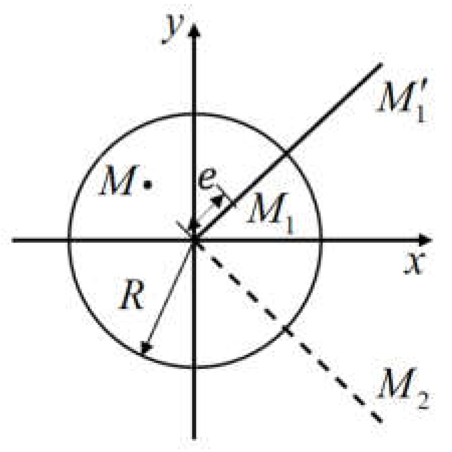
Figure 1. Schematic diagram of a seepage field inside a circular pit.
Applsci 13 12647 g001
Figure 2. Schematic diagram of conformal mapping of ellipsoids.
Applsci 13 12647 g002
Figure 3. Seepage field inside elliptical pit cut-off wall.
Applsci 13 12647 g003
Figure 4. Schematic of pit profiles under the IDPR scheme: (a) Pressure-bearing mode; (b) submerged mode. “Reproduced with permission from Zhu D. et al. [18], Simplified calculation and design method of multi-well system for anti-uplifting based on intercepting and discharging water; published by Chinese Journal of Geotechnical Engineering, 2021”.
Applsci 13 12647 g004
Figure 5. Design flowchart for IDPR anti-floating system.
Applsci 13 12647 g005
Figure 6. Schematic diagram of relief well scheme for elliptical pit arrangement: (a) Pit 1 using the A-well distribution method; (b) Pit 1 using the B-well distribution method; (c) Pit 1 using the C-well distribution method; (d) Pit 2 using the A-well distribution method; (e) Pit 2 using the B-well distribution method; (f) Pit 2 using the C-well distribution method; (g) Pit 3 using the A-well distribution method; (h) Pit 3 using the B-well distribution method; (i) Pit 3 using the C-well distribution method.
Applsci 13 12647 g006
Figure 7. Comparison of flow results in pressure-bearing mode (m3/d).
Applsci 13 12647 g007
Figure 8. Comparison of flow results in submerged mode (m3/d).
Applsci 13 12647 g008
Figure 9. Distribution of site head error inside the elliptical pit cut-off wall in pressure-bearing mode (%): (a) The working condition with the minimum total head error; (b) the working condition with the maximum total head error.
Applsci 13 12647 g009
Figure 10. Distribution of site head error inside the elliptical pit cut-off wall in submerged mode (%): (a) The working condition with the minimum total head error; (b) the working condition with the maximum total head error.
Applsci 13 12647 g010
Figure 11. Comparison of results of elliptical pits with different aspect ratios calculated using different simplified methods in the pressure-bearing mode: (a) Elliptical pit with a = 90 m, b = 70 m; (b) elliptical pit with a = 100 m, b = 60 m; (c) elliptical pit with a = 120 m, b = 50 m; (d) elliptical pit with a = 160 m, b = 40 m.
Applsci 13 12647 g011aApplsci 13 12647 g011b
Figure 12. Schematic diagram of the location of the relief wells in the garage. “Reproduced with permission from Zhu D. et al. [12], Application of interception and drainage anti-floating system in treatment of uplift accidents; published by Chinese Journal of Geotechnical Engineering, 2018”.
Applsci 13 12647 g012
Figure 13. Comparison of seepage field distributions on the inside of the cut-off wall: (a) Seepage field obtained from simplified calculations; (b) seepage field obtained from finite element calculations.
Applsci 13 12647 g013
Table 1. Normal working condition fixed value parameters.
R0 (m)nhw (m)H0 (m)D (m)K (cm/s)K0 (cm/s)K1 (cm/s)Kw (cm/s)
400.00200.006.002.50 5 × 10 2 5 × 10 2 5 × 10 4 5 × 10 5
Table 2. Pressure-bearing model program parameters.
a (m)b (m)T0 (m)T1 (m)Distributionrw (m)T (m)d (m)
90702.005.00A0.500.600.80
100603.004.00B1.001.001.60
120504.003.00C---
Table 3. Submerged model program parameters.
a (m)b (m)T0 (m)T1 (m)z0 (m)Distributionrw (m)T (m)T2 (m)d (m)
90702.507.507.50A0.500.503.500.80
100603.007.007.00B1.000.803.201.60
120503.506.506.50C----
Disclaimer/Publisher’s Note: The statements, opinions and data contained in all publications are solely those of the individual author(s) and contributor(s) and not of MDPI and/or the editor(s). MDPI and/or the editor(s) disclaim responsibility for any injury to people or property resulting from any ideas, methods, instructions or products referred to in the content.