Article

Study on the Effect of Rock Mass Structure on CO2 Transient Fissure Excavation

1
Institute of Geology and Geophysics, Chinese Academy of Sciences, Beijing 100029, China
2
College of Geoscience and Surveying Engineering, China University of Mining and Technology (Beijing), Beijing 100083, China
3
Research Institute of Highway Ministry of Transport, Beijing 100088, China
4
University of Chinese Academy of Sciences, Beijing 100049, China
5
China Earthquake Disaster Prevention Center, China Earthquake Administration, Beijing 100029, China
*
Authors to whom correspondence should be addressed.
Appl. Sci. 2023, 13(23), 12666; https://doi.org/10.3390/app132312666
Submission received: 15 September 2023 / Revised: 17 November 2023 / Accepted: 18 November 2023 / Published: 25 November 2023

Abstract

:
As a new rock breaking method, CO2 transient cracking has been widely used in rock excavation projects in recent years. However, in the actual construction process, there are often situations where the fracturing effect varies due to different rock mass structures. Through theoretical analysis and on-site cracking tests, this article studies the effect of CO2 transient cracking under the control of different rock mass structures. The results show that: (1) the dynamic compressive strength of rock directly determines the number and range of dynamic impact fractures; the original fractures of rock mass and those caused by dynamic impact in the first stage jointly determine the effect of high-pressure gas expansion in the second stage. (2) The arrangement of holes along the strata is conducive to the action of high-pressure expanding gas along the soft structural plane in the rock mass, which is conducive to the fracturing of the rock mass; the amount of crack formation is small, but the influence range is large. (3) The cracking effect of carbon dioxide transient cracking applied to massive rock mass is better than that of monolithic rock mass, while the cracking effect of layered rock mass with soil interlayer is poor. The research results are of great significance for improving the effectiveness of carbon dioxide transient-induced cracking excavation and guiding actual construction.

1. Introduction

In recent years, the quantity of construction sites in the urban region, including subway construction, building foundation pit excavation, etc., has increased. Enslaved to the strict requirements of the construction environment, improvement of work efficiency based on the guarantee of construction safety has become an important task of the current kind of engineering project in construction. It has been urgent to comprehensively promote the rock cracking excavation technology in the engineering field. Seeking some efficient and safe rock cracking technologies is deemed one of the most important development directions for rock excavation at present and even in the future [1].
Common rock cracking excavation methods can be mainly divided into the blasting method and the non-blasting method. Explosive rock breaking, which is widely used, belongs to the blasting method. The blasting method is good for the rock breaking effect, high in cost performance, etc., but many significant problems exist, including the flying stone, vibration, dust, noise, etc. The non-blasting method includes the static crushing method with an expansive agent, the mechanical crushing method with a hammer, etc. [2,3]. Static rock cracking refers to the method of adding a static expansion agent with calcium oxide as the basic component to crack a hole. Due to its expansion effect, under the constraint of a hole wall, expansion pressure is generated along the radial direction to crack the rock mass. Due to low efficiency, long construction time, high construction cost, etc., the method is difficult to apply to large-scale construction. The mechanical crushing method refers to the use of mechanical equipment (such as a rock drill), impact rock, and dynamic rock crushing. This method has some problems, such as high fuel consumption and high equipment wear. The transient cracking technology of liquid carbon dioxide, a kind of new non-blasting rock excavation method, is simple and convenient in operation, safe, efficient, etc. [4]. Its small scope of vibration and low strength would avoid the strong vibration, which can damage buildings and overcome the drawback of the traditional rock breaking method.
Originating from the 1950s and proposed by American researcher Langelle Doakes for the first time [5], such technology is mainly used to exploit the high-gas coal mine. China introduced the cracking technology at the beginning of the 1990s [6]. Many researchers have deeply researched the control mechanism of the cracking effect. The research results of Shao Peng et al. show that, in the isothermal condition, the entire process of the high-pressure gas blast could be deemed the cooling and expansion process of high-pressure gas. He proposes that, with the increase of medium strength, the pressure needed for crushing of the medium presents nonlinear growth [7]. Guo Zhixing et al. propose such technology is most applicable to the porous and fragile materials for cracking [6]. The research results of the foreign S.P.Singh show that the cracking rock aims to form the penetrating cone-shaped fissure [8]. Zhou Xihua et al. start from the theoretical level to divide the entire cracking process into the rapid gasification stage, slow rising stage, dramatic decrease stage of energy leakage, and remaining stage [9]. Xiao Chengxu et al. carry out a multigroup contrast test, which starts from the difference in tube body structure. The research results indicate that the thickness of a constant pressure sheet would significantly affect the transient cracking role effect of carbon dioxide [10]. Ma Haipeng et al. think that the method of improving the cracking effect by increasing the filling weight of carbon dioxide is relatively applicable to the rock, which is loose and poor in leakproofness as a whole [11].
After the analysis of the existing research results, it is easy to find that the restriction mechanism of rock structure effect in transient cracking rock has not been clear and has become the key factor of low benefit and instability in the rock cracking excavation process. Therefore, in the theoretical analysis, etc., the cracking difference of distinct rock structures is researched, and the control mechanism of different rock structures for the transient cracking effect of rock is ascertained, combined with different rock statuses and the field test at different cracking working conditions, which is of important significance in improving the transient cracking excavation effect of carbon dioxide and in guiding the actual construction.

2. Theoretical Analysis

2.1. Fundamental of Cracking Role

The carbon dioxide in daily life mostly exists in the form of gas, but at high pressure (8~10 MPa) and at normal temperature (below 25 °C), the carbon dioxide exists in the form of a liquid state. At this very time, when the transient temperature surpasses 31.2 °C with the change of status, the liquid carbon dioxide would rapidly gasify, and its volume would also rapidly swell 500 times at most. Under the high-pressure swelling, the gas crushes the cracking pipe and rushes out of the pipe body, then the shock airstream formed by high-pressure gas is generated and directly acts on the rock touched by the cracking pipe in the form of dynamic load [12,13]. In this process, lots of fissures will be generated in rock [14]. Newly generated fissures and the original fissure of the rock constitute the fracture mesh [15]. Cracks exist alone, and there is no connection between cracks and cracks. When the cracks are connected to each other, a fracture mesh is formed. The penetration of the fracture mesh eventually leads to the fragmentation and separation of the rock mass. On account of the very short change time, the entire phase change process could be basically accomplished within 0.4~0.5 s. Therefore, the cracking role could be called the transient cracking role of carbon dioxide.

2.2. Analysis of Cracking Process

The transient cracking of carbon dioxide generally adopts the step working surface [16]. The transient cracking pipe of carbon dioxide is embedded at the bottom of the cracking hole, and the transient cracking also acts on the inside of the rock; therefore, it is difficult to intuitively analyze the cracking process inside the rock. Currently, in the academic circle, the following theory is acknowledged widely: the transient cracking rock process of carbon dioxide could be mainly divided into two stages [17]. The first stage implicates the impact effect of dynamic load; the second stage implicates the swelling role of gas.

2.2.1. Impact Effect of Dynamic Load

The transient cracking of carbon dioxide mainly acts on the inside of the rock. After crushing the cracking pipe, the shock airstream formed by high-pressure gas directly acts on the rock contacted by the cracking pipe. The rock mass is fractured by fracturing when the fracturing pipe is broken, and the shock wave produced by the impact gas flow exceeds the dynamic compressive strength of the rock mass. The areas showing different distances with the cracking hole present an obvious division scope of cracking characteristics at the macro level [18]. As shown in Figure 1, the action zone of a dynamic load of transient cracking of liquid carbon dioxide could mainly be divided into three parts: 1-crushed zone close to the cracking hole, 2- fissure zone formed due to fissure expansion in the crushed zone, 3- vibration zone away from the cracking zone.

2.2.2. High-Pressure Gas Expansion

After the completion of the dynamic load impact effect at the first stage of transient cracking of carbon dioxide, the high-pressure swelling gas would rapidly enter the rock fissure for expansion. When the high-pressure gas expands into the rock mass fracture, the expansion force generated exceeds the mechanical strength required for the fracture tip to maintain stability, and the fracture expands. Only when the swelling gas pressure is decreased till it is difficult to drive the fissure for continuous expansion or till the fissure forms the fissure channel connecting the surface of the rock can the high pressure of swelling gas be completely released. At this time, the transient cracking process of carbon dioxide completely ends.
Therefore, the structural surface existing in the natural rock and the fissure generated in the dynamic load impact affect the role at the first stage of transient cracking of carbon dioxide, which would play the main control role in the dynamic swelling process of high-pressure gas at the second stage of transient cracking.

2.3. Control of Rock Mass Structure

In general conditions, the rock structure effect existing in the field of explosive rock breaking is also applicable to the transient cracking process of carbon dioxide. The rock of massive structure is classified as the rock with difficulty in blasting. With the increase of the crushing degree of rock structure, the cracking difficulty of rock decreases accordingly. The dynamic load impact effect at the first stage would decrease to some extent, and the shock wave generated in the transient cracking role of carbon dioxide would unavoidably speed up the attenuation velocity due to the increase of the quantity of structural surface. However, with the increase in the quantity of structural surfaces, the subsequent high-pressure gas swelling role at the second stage would generate a better effect at the expansion-break-through stage of the fissure. Of course, a larger quantity of structural surfaces certainly would not generate a better effect. When the rock is crushed to a certain degree, the transient cracking role of carbon dioxide will cause the inside of the rock to rapidly generate the fissure connecting the free surface. It is too late for the high-pressure swelling gas at the second stage of transient cracking to act on the rock, and then the high-pressure swelling gas would release in the connecting fissure, so the cracking effect would decrease accordingly.
To sum up, the transient cracking of the carbon dioxide effect would tend to increase at first and then decrease with the development of the rock’s structural surface and the increase of the crushing degree of rock structure. The crushing degree of rock controls the cracking effect at the critical point with the optimal cracking effect.

3. Influence of Angles between Different Structural Surfaces (Test 1)

The structural surface with significant development often exists in the rock. In the actual construction process, the cracking hole is drilled generally in the method of being perpendicular to the ground to facilitate the construction [19]. However, the influence of different cracking holes and different included angles on the significant structural surface on the cracking effect cannot be ignored. The No. 1 test site with different cracking holes and different included angles on the significant structural surface is arranged to research the influence of different included angles between cracking holes and structural surfaces on the cracking effect.

3.1. Overview of No. 1 Test Site

The No. 1 test site is situated at a certain limestone mine in Qingzhen City, Guizhou Province. Qingzhen City is one of the more developed regions in Guizhou Province in terms of economy and culture [20]. Many documents and literature concerning the research results of the region show that the region is mainly the karst topography [21,22]. In the subsequent site survey process, it was also found that the underground karst in the test field area is relatively developed, there is a cavity in the rock at the mine location, the overall fissure is relatively developed, and the brown dip-dyeing phenomenon exists near the fissure and on the surface of some rocks mainly due to the intrusion of underground water. The weathering surface presents a yellow and yellowish brown, and few secondary minerals exist in the joint fissure.
The vertical height of the free face for the test site is 3.12 m–4.68 m. The exposed rock stratum on the step’s working face could be divided into two layers of parallel rocks. The thickness of the single layer is 1~1.5 m, and the attitude of the bed is 90°∠15°.

3.2. Test Presentation

3.2.1. Integral Test Procedure

1.
Preparation before the test starts
According to the actual situation of the mine site, the appropriate location is selected as the test area, and the location of the crack hole is demarcated. In the calibration process of the cracking hole, ensure that the resistance line (the distance from the cracking hole to the free surface) and the hole depth in the test process are the same, and carry out a field test.
2.
Arrange the cracking device
Drilling is carried out by the rig at the designated position according to the established scheme. Professional technicians will test the tightness of the crack tube, lower the assembled crack tube to the bottom of the crack hole, and check the line connectivity. After confirming that all line connections are correct, backfill and seal holes. The red carpet is placed at a distance of 5~10 m from the crack hole in the upper step area as a reference.
Inform the site construction personnel and other equipment to withdraw from the test site 200 m away and connect the crack pipeline with the detonator.
3.
Perform field cracking test
The remote control flew the drone to a position 40 m above the crack test area, and the camera of the drone was vertical to the ground for a 4K camera. In order to avoid damage to the UAV caused by accidents such as “flying tube” and “flushing tube”, the UAV avoids directly above the crack hole.
After the professional and technical personnel confirm again, the explosion begins. After the carbon dioxide transient cracking effect is completed, the drone camera and photo are ended, and the drone is recovered.
4.
Obtain test data
After the technicians reconfirm the safety of the site, they enter the test site, measure the size of the rock one by one, and calculate the effective cracking square amount and the influence range of the cracking. Take images of fissures in the air surface of the scene. To be further analyzed and processed in the laboratory.

3.2.2. Layout Parameters

The test adopts the method of “joint detonation and analysis one by one”. To reduce the mutual influence among joint detonation and to facilitate distinguishing the difference among single-hole cracking, the hole pitch is increased in the test layout. Parameters of the cracking pipe and actual hole layout are are shown in Table 1 and Figure 2.
The direction of level determines three kinds of hole layout methods, namely the hole layout of consequent rock stratum, the hole layout vertical to the ground, and the hole layout of inverse rock stratum. At the construction site, the cracking hole of the inclination angle is drilled based on the right-angle side ratio of 1:10. The calculation results of the trigonometric function show that the inclination angle is about 6°.

3.3. Analysis of Cracking Effect

The simultaneous initiation method is adopted, so the cracking effect of different pipes shall be divided. The frame-wise interception method is adopted to capture the videos shot in the cracking process into pictures. Based on the rock bulging in the cracking process, the crushing trend, rock tumbling, etc., the cracking influence zones of different pipes are divided. The rock is recognized and annotated with the exclusive MIPS software of the Institute of Geology and Geophysics, Chinese Academy of Sciences, based on the image gray value difference [23]. Based on the site and image information, the cracking effect of this cracking test is analyzed, with the following parameters mainly considered: the cracking influence scope, effective cracking square amount, fractal dimension, bounder yield, bulk factor, the farthest distance of flying stone, and free face after blasting.
Finally, the rock recognition image is shown in Figure 3. To facilitate the observation, only the rock with a size of more than 1m is annotated on the image.

3.3.1. Division of Cracking Influence Zone

The effective area of cracking refers to the visible significant rock disturbance area generated in the cracking role, including the rock crushing zone and fissure extension zone. The rock crushing zone concretely refers to the zone separating from the rock on account of the carbon dioxide transient cracking and direct crushing. The fissure extension zone refers to the influence zone developed and extended by the fissure generated due to the carbon dioxide transient role and is demarcated by the farthest distance of fissure extension. The division scope after cracking and the site plane before cracking are fit via site calibration and combined with the processing and analysis of the cracking effect plan in the later period. As shown in Figure 4, the scope on the left of the black dotted line is the blast heap scope after the cracking of the cracking hole, while the scope on the right of the black dotted line is the effective cracking scope of the corresponding cracking hole. The blue round near the digital is the position of the cracking hole.
The effective cracking zone of the No. 1 hole is 5.11 m2; the effective cracking zone of the No. 2 hole is 13.20 m2; the effective cracking zone of the No. 3 hole is 8.68 m2; the effective cracking zone of the No. 4 hole is 28.08 m2, with the largest scope, mainly because the large-scope fissure influence area is formed due to fissure extension. The No. 4 cracking pipe adopts the attitude hole layout on the inverse rock stratum, and the cracking finally leads to the 30 cm width fissure. The surface of the rock on both sides of the fissure is relatively smooth, and the fissure extension length reaches about 11.30 m. There is an effective cracking of the rock in No. 1, 2, and 3 holes, but no extension fissure is generated. No. 4 hole generates wide fissures under the cracking role, mainly due to the following causes: the hole layout on the inverse rock stratum cannot effectively keep away from the rock after the rock cracking and crushing. Moreover, due to the original weathering interface, the high-pressure swelling gas expands the fissure along the structural surface of thin and soft rock.

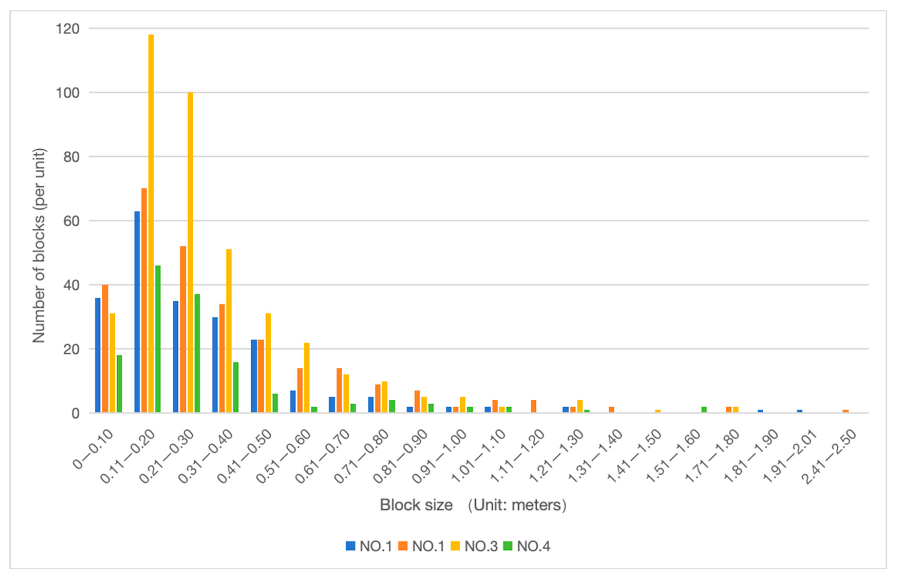
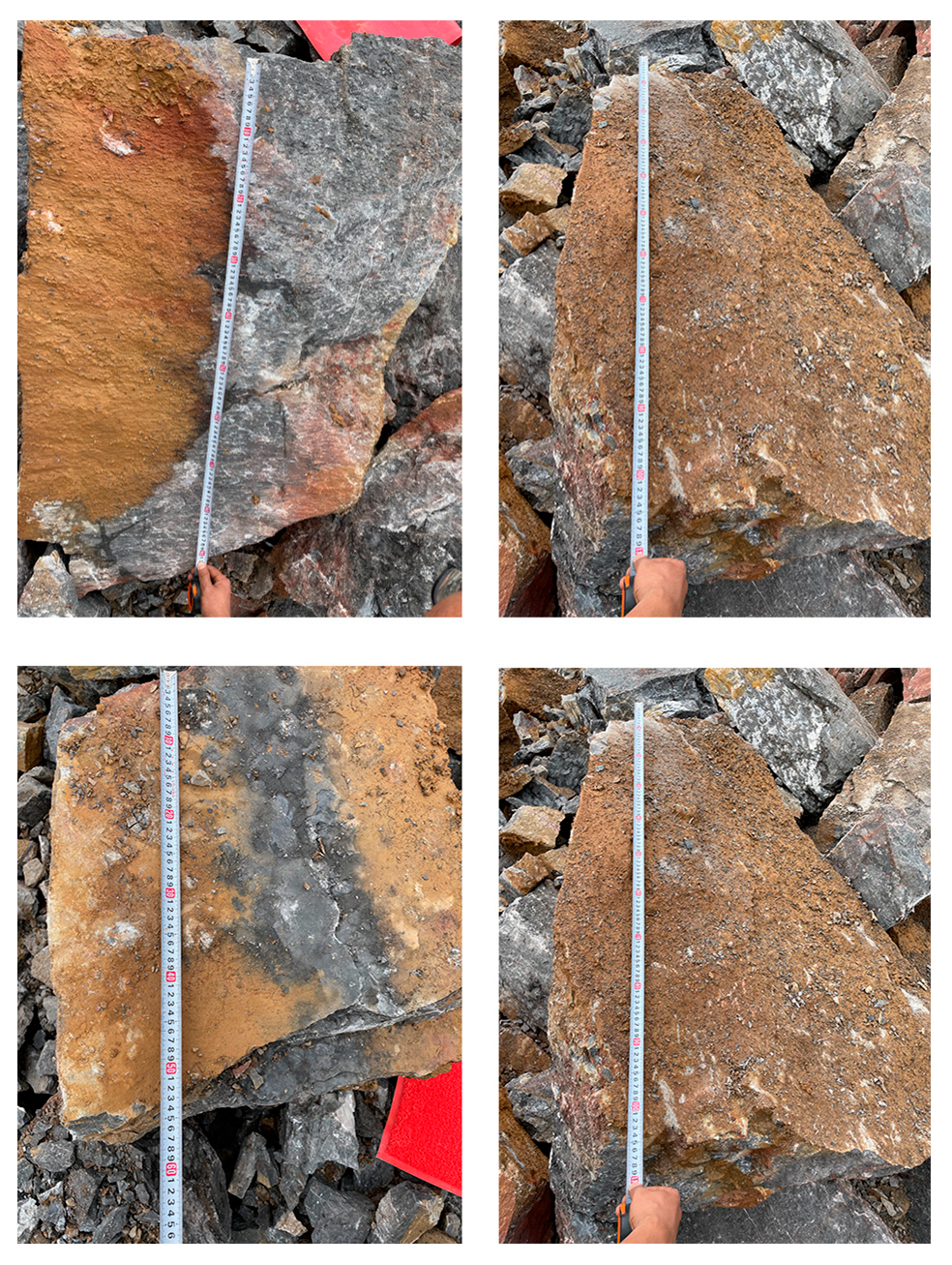
3.3.2. Effective Cracking Square Amount

Effective cracking square amount, deemed an important index to characterize the rock cracking effect, means the total square amount of rock block that is crushed and completely keeps away from the original rock body under the transient cracking role of carbon dioxide.
As shown in Figure 5, No. 1 hole’s effective cracking square amount is 4.53 m3; No. 2 hole’s effective cracking square amount is 20.80 m3; No. 3 hole’s effective cracking square amount is 14.60 m3; No. 4 hole’s effective cracking square amount is 8.64 m3. No. 1 and No. 4 holes adopt the vertical hole layout, in which No. 1 fails to give full play to the cracking effect because its free face height is less than 4m, corresponding to the minimum square amount. No. 2, 3, and 4 holes adopt the attitude hole layout of the consequent rock stratum, vertical hole layout, and attitude hole layout of the inverse rock stratum, respectively. The No. 2 cracking square amount is 1.42 times the cracking square amount of the No. 3 cracking hole and 2.41 times the cracking square amount of the No. 4 cracking hole. Thus, it can be seen that, in terms of the cracking square amount, the consequent rock stratum presents the optimal hole layout and cracking effect.
Combined with the above theoretical analysis, the hole layout of the consequent rock stratum is conducive to the high-pressure swelling gas generated by cracking acting on the structural surface of the rock and beneficial to the collapse and unloading of upper layer rock along the rock stratum under the double action of gravity and high-pressure gas expansion.

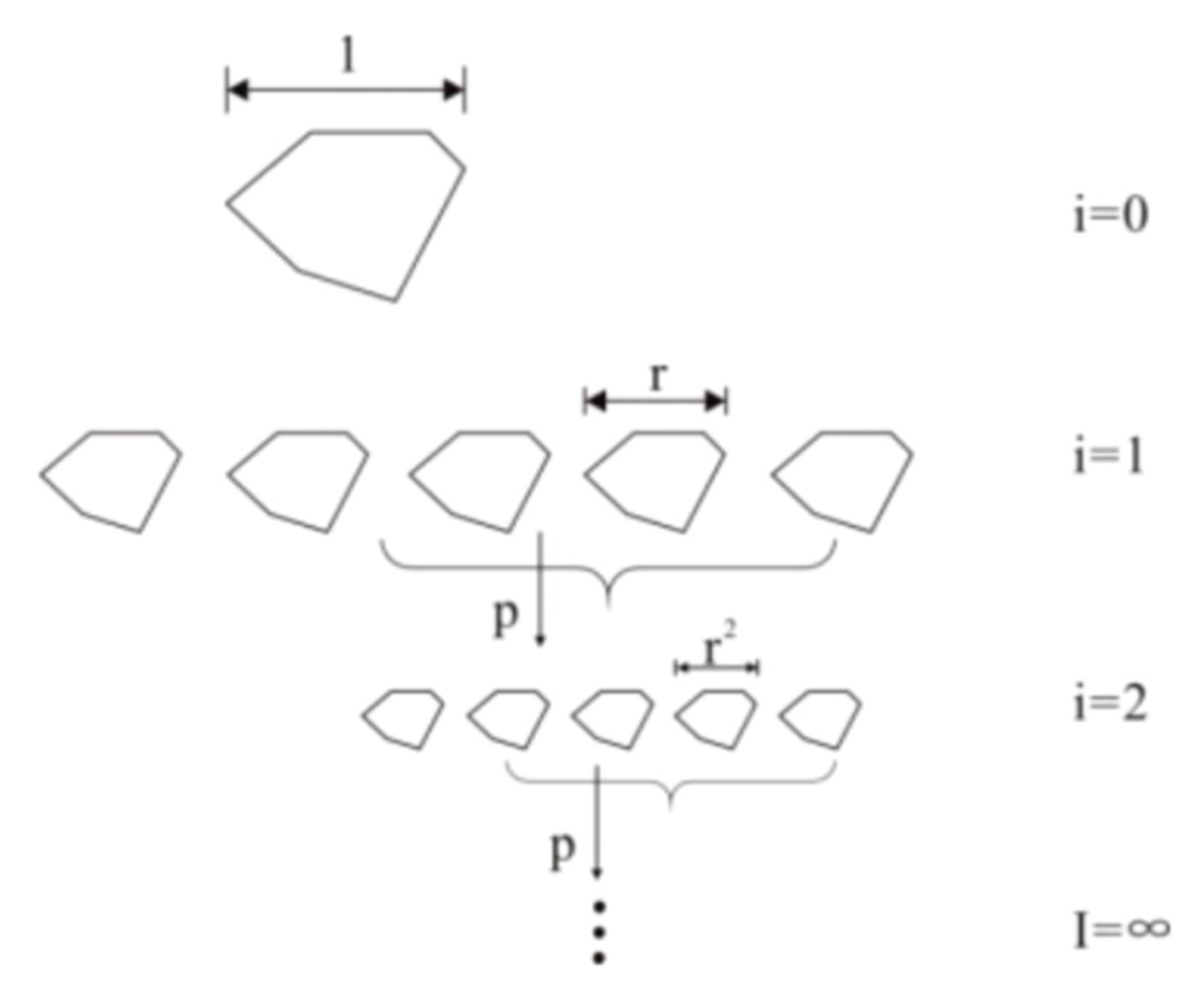
3.3.3. Evaluation of Fractal Dimension

The fractal dimension is the quantitative index to measure the block lumpiness distribution. The analysis results of geometrical shape show that several rocks formed after rock breakage in the natural state own similar characteristics to the original rock shape, as shown in Figure 6. The analysis results of size show that the secondary rock formed after rock breakage in its natural state could be considered to be formed by the original rock crushed as per a certain proportional length. To sum up, the rock formed by a rock after the transient cracking and crushing of carbon dioxide is similar. The rock mass distribution of different cracking tubes measured on-site is shown in Figure 7.
Xie Heping et al. deeply analyze the rock fracture and the crushing fractal [24]. Based on the rock rupture theory, the fractal dimension calculation function between rock crushing size and quantity is proposed:
N = N 0 R / R m a x D
Type in the
D is the fractal dimension;
N is the number of fragments whose size is above R;
R is the feature size selected according to the actual situation, unit: m;
Rmax is the maximum size of the rock block after fracturing (unit: m);
N0 The number of rock fragments of maximum size.
The fractal dimension of rock after cracking of cracking pipes is basically between 1.3~1.9, as shown in Table 2, in which the fractal dimension of the No. 2 pipe is the maximum one, namely 1.86, and the fractal dimension of the No. 3 pipe is the minimum one, namely 1.37. The fractal dimension of each cracking pipe after the action is more than 1 and presents a good fractal feature.

3.3.4. Bounder Yield

The bounder yield generally refers to the rock proportion that does not conform to the size and volume requirements in the reprocessing process. In this test, the rock with a single-side size of more than 1m is selected as an unqualified block based on the rock size requirement of the site limestone processing equipment. The rock with a size of more than 1m shall be crushed again. The measurement of a part of large rock mass after cracking is shown in Figure 8. Detailed mass data are shown in Table 3.
The massive rock generated by single-hole cracking is large in volume. Yellow, moist soil exists on the surface of the massive rock after cracking inordinately. The surface of the soil is mainly considered as the weathering fissure surface of the original step rock formed due to water intrusion. The weathering fissure surface is the dominant action surface of the cracking process. The weathering penetrated surface restricts the transient cracking of carbon dioxide, and the high-pressure gas expands along the fissure of the surface after swelling. As a result, the massive rock resulting from cracking is oversized.

3.3.5. The Loose Coefficient

The coefficient of looseness is deemed the basis for rock cleaning and transportation after cracking. Based on the site measurement and the image division in the later period, the corresponding blast heap volume of the No. 1–4 cracking hole is 7.34 m3, 25.70 m3, 20.46 m3, and 13.64 m3, respectively. There is a gap between the broken stones, so the total volume of blast heap formed by each cracking pipe is more than the total square amount of effective fracking. The loosening coefficient of each hole blasting pile after cracking is shown in Table 4: the coefficient of looseness of the blast heap of each hole after cracking is more than 1.2, which certifies that, after the cracking, the rock is good in looseness degree, which is conducive to cleaning and carrying on the site.

3.3.6. Statistics of Flying Stone Distance

Since the rock at the bottom is crushed and deformed, the overlaid rock breaks away from the rock under the high-pressure swelling gas and collapses, tumbles down, and separates from the rock to form the flying stone. The farthest distance of the flying stone from the No. 1 hole is 11.76 m, and the rock size is 0.49 m; the farthest distance of the flying stone from the No. 2 hole is 15.60 m, and the rock size is 0.44 m; the farthest distance of the flying stone from the No. 3 hole is 34.20 m, the flying stone size is 1.10 m, and flying stone volume reaches 0.38 m3. The flying stone is deemed the one with the maximum volume. The nearest distance of the flying stone from the No. 4 hole is 7.44 m, and the rock size is 0.33 m.
For this test only, the flying stone distance of the vertical hole layout is the largest (as shown in Figure 9), and that of the reverse hole layout is the smallest.

3.3.7. Free Face after Blasting

As shown in Figure 10, the comparison results of the free face before and after cracking and the free face after cleaning and carrying show that:
In the No. 1 cracking pipe action zone, the rock at the bottom of the free face at the rear edge is crushed, and the size of the crushed rock is relatively collective. At the development position of the original rock fissure, the crushing effect is better, and the rocks focus on small size more. The rock on the rear edge of the free face is crushed mainly because the burial depth of the No. 1 pipe is larger than the height of the free face, and some energy destroys the free face on the rear edge.
Lots of yellow soil exists on the surface of the rock after blasting in the No. 2~3 cracking pipe action area, and the free face after blasting regards the yellow moist soil as the interface. Such weathering-penetrated surfaces obstruct the destruction of the rear edge of the rock by the cracking role and control the total square amount of cracking to some extent. Although there are large-size rocks in the No. 4 cracking pipe zone, which do not break away from the original rock, the large-size rocks can be effectively cleaned up after being loosened by an excavator. The rear edge free face in the No. 2~4 cracking pipe action zone is relatively neat to facilitate the progress of the subsequent step working face.

3.4. Analysis of Cracking Effect

This test could work out that the rock structural surface and the included angle of the cracking hole generate significant influence on the cracking effect:
(1)
The coefficient of looseness of each pipe after cracking conforms to the requirements. In addition, the bounder yield of each cracking pipe surpasses 5% of standard requirements. The hole layout cracking of the consequent rock stratum owns maximum cracking square amount and maximum fractal dimension.
(2)
When there is an apparent level in rock, the hole layout effect of the consequent rock stratum is optimal; the vertical-dipping bed attitude is second in the cracking effect; the inverse rock stratum attitude is worse in the cracking effect and cannot carry out effective cracking of rock, but generates farther range. The hole layout of the consequent rock stratum is conducive to rock unloading: High-pressure gas could expand the fissure along the thin and soft rock stratum, and the rock easily separates from the rock body along the formed fissure.
(3)
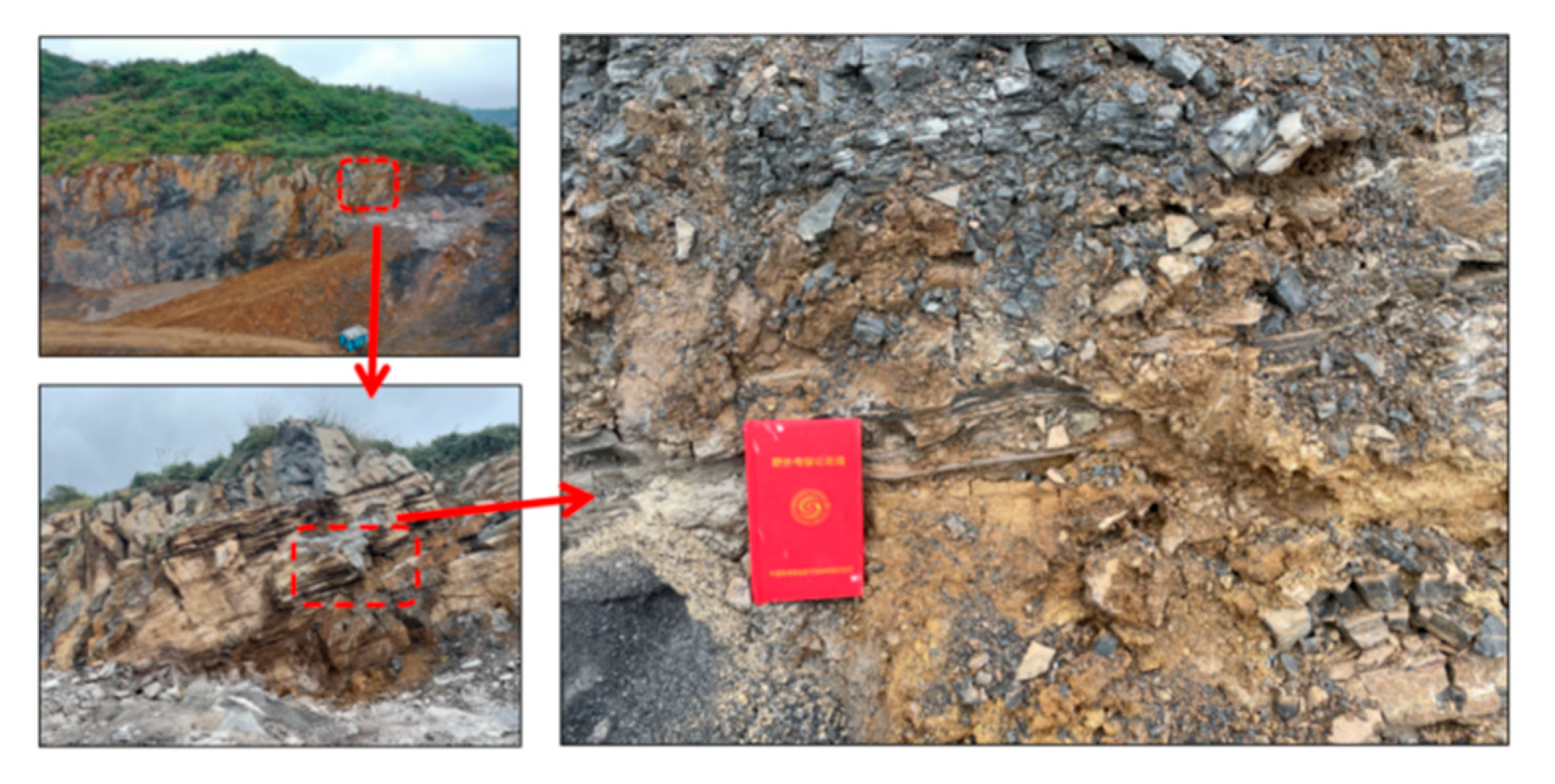
The old weathering surface existing in the rock contains the total square amount of cracking to some extent. Lots of wet yellow soil exists on the surface of the rock after blasting. The free face after blasting deems such yellow wet soil as the interface. Such weathering of a surface controls the total square amount of cracking to some extent.

4. Control Role of Different Rock Structures

To research the control role of the cracking effect by different rock structures, the check test is supplemented. The No. 2 test is situated in a certain limestone mine, Qingzhen City, Guizhou Province, and the layered structure rock is selected for the test. The No. 3 test and No. 4 test are situated at a certain granite mine in Yiyang, Hunan. The overall process concerning site test layout is the same as the above test process, which is not repeated in the subsequent contents, and only the difference is supplemented.

4.1. Limestone with Layered Structure

4.1.1. Overview of Site

The No. 2 test site is still situated at the limestone mine of the No. 1 test site. The rock in the transient cracking role zone of carbon dioxide is adopted as a layered structure in the test zone (as shown in Figure 11). The free face height of the site is 8 m, and there is a 4 m blocky structure in the upper zone; there is a 4 m layered structure in the lower zone, and the thickness of the thin layer is 1 cm.

4.1.2. Test Layout

Parameters of the cracking pipe and actual hole layout are shown in Table 5 and Figure 12.

4.1.3. Cracking Effect

The No. 1 and No. 2 cracking pipes act and generate a “washpipe”, and the high-pressure gas emits from the cracking hole. Such cracking fails to reach the ideal effect and cannot effectively crush the rock. The No. 3 cracking hole releases high-pressure gas at the bottom of the rock and smoothly crushes the layered rock at the bottom. The high-altitude overhead shot after cracking of hole No. 3 is shown in Figure 13. The “washpipe” between the No. 1 and No. 2 cracking pipe mainly results from the loose hole sealing. The cracking energy generates the spillage, so the No. 1 and No. 2 cracking pipe would not be mainly analyzed. The role effect of the No. 3 cracking pipe is mainly analyzed.
The situation after cracking on site is shown in Figure 14. After completion of cracking, the No. 3 hole acts on the lower middle position of the local zone, the rock is crushed in a small scope, and the soil in the rock erupts from the interlayer. Lots of fresh yellow soil blocks in the rock spurts due to being swollen and extruded by high-pressure gas, and the diffusion region of loss extruded from inside of the rock is crushed in the thin layer of flake rock. The size of the crushed thin layer rock is 4–20 cm, and the thin layer rock is crushed mainly along the bedded rock. The total square amount of fractured and crushed rock is 1.10 m3. In addition, no apparent rock fissures and remote flying stones are generated.

4.2. Granite of Whole Structure

4.2.1. Overview of Site

A certain granite mine in Taojiang County, Hunan Province, is selected as site II. The overall condition of the site is shown in Figure 15. The second intrusive body, Taojiang granite rock in the later period of Caledon, is mainly exposed in the mine. The construction site of the mine has been mined to the bottom rock, which belongs to the slightly weathered rock, and the rock in that zone could be divided into a massive structure [25,26]. The rock is abnormally stiff, and the rock joint fissure is not developed. The residual slope accumulation layer is sporadically distributed in the surrounding area; the developed fissure could be seen in partial location, mostly in front of the mountain or at the toe of the side slope. The No. 3 and No. 4 test adopt the hole layout vertical to the ground.

4.2.2. Parameter Layout

The concrete hole layout parameters of the No. 3 and No. 4 tests are shown in Table 6.

4.2.3. Cracking Effect

The rock could not be effectively cracked in the No. 3 test, and no new fissure was generated in the site cracking without an obvious cracking effect. In the cracking process, each cracking pipe generates the “washpipe”, namely the high-pressure gas emitted from the cracking hole, as shown in Figure 16, which causes the flushing hole mouth height of broken stones and stone powder backfilled in the pipe to reach over 20 m.
As shown in Figure 17, the No. 4 test only generates one deep, large penetrating fissure with a width of 0.30 cm. The free face extends for about 5 m in the vertical direction, and the upper step surface extends for 4 m in the horizontal direction.

4.2.4. Analysis of Test Results

The No. 3 and No. 4 tests failed to obtain effective cracking, mainly due to the following causes: ① The granite is hard in rigidity and good in intactness, without a weak structural surface. The rock has great dynamic compressive strength of power, the impact effect generated by transient cracking cannot crush the rock and form a fissure net, and the high-pressure gas is emitted along a single fissure. ② There is little waterlogging in the drilling hole, which cannot be completely compacted and reduces the backfilling seal effect of cracking the hole, leading to a “washpipe”. The above analysis results show that the carbon dioxide transient cracking is the fissure net generated by the rock fissure connecting the original fissure of rock to reach the cracking. The rock structure plays a certain role in controlling the carbon dioxide transient cracking effect.

5. Comprehensive Comparison and Analysis

The transient cracking role of liquid carbon dioxide acts on the step rock. In the first step, the high-pressure gas is released from the pipe and ejected into the cracking hole wall rock to form the dynamic load role. The second step is the dynamic physical interaction after the expansion of high-pressure gas. The former leads to the damage and fracture of rock, forming lots of fissures; the latter extends the fissure, making rock fragments separate from the rock body. It shall be noted that, on account of the transient cracking role of carbon dioxide, some rock bodies in the upper area of the free face tumble under self-weight conditions, thus becoming crushed. After the rock in the local horizontal area of the cracking pipe is effectively crushed and separated from the original step rock body, the overlying rock may be damaged even with sufficient cracking.
The comprehensive comparison results of four tests show that the rock structure plays a significant role in controlling the cracking effect. The specific analysis results are as follows:
(1)
The comparison results of the cracking effect of three kinds of hole layout methods in the No. 1 test show that the hole layout of the consequent rock stratum is conducive to giving play to the role of high-pressure swelling gas along the soft (weak) structural surface in the rock, and is beneficial to the cracking and crushing of rock and separating from the original rock. The rock after cracking is great in fractal dimension, large in the effective square amount of cracking, and good in the cracking effect. The hole layout cracking on the inverse rock stratum is small in square amount, but the formed fissure is large in area and influence scope.
(2)
The comparison results of the No. 1 and No. 4 tests show that the cracking effect of carbon dioxide transient cracking role in the massive structure rock is superior to that in the whole structure rock. The carbon dioxide transient cracking is “lazy” because it would crush the weak position in the rock in priority. For the rock with good intactness, the rock structure controls the cracking effect in the dynamic pressure resistance of rock and tensile strength. The larger the mechanical strength of the rock is, the more difficult the rock is cracked under the role of transient cracking of the first stage. At this time, the cracking role mainly implicates the “fissure creation.” When the rock is poor in intactness, the rock structure controls the cracking effect in the development condition of the structural surface. The cracking role mainly expands the detritus along the original deep fissure weathering surface. The transient cracking focuses on the dynamic impact effect.
(3)
When the cracking pipe fails to crack the rock and form the fissure connecting to the surface, the high-pressure swelling gas cannot be emitted in the rock, then acts on the backfilling position of the cracking hole, leading to the “washpipe” and “flying tube”. At this time, compared with the first generation of disposable cracking pipe, the second generation of recyclable cracking pipe’s safety decreases greatly.
(4)
The soil interlayer in the rock would severely weaken the cracking effect, deepen the weathering surface, and certainly control the effective square amount of cracking.

6. Conclusions

The above test could work out the following conclusions:
(1)
The carbon dioxide transient cracking role could be divided into two processes. The dynamic impact effect is mainly reflected in the rock crushing and fissure producing, while the static swelling role mainly acts on the fissure expansion and promotion of connection, thus reaching the rock cracking effect. The dynamic pressure resistance strength of rock directly determines the quantity and scope of “fissure created” under the dynamic impact effect.
(2)
The hole layout on the consequent rock stratum is conducive to the high-pressure swelling gas-crushing rock, with a good cracking effect. The hole layout cracking on the inverse rock stratum is small in square amount, but the formed fissure is large in area and influence scope.
(3)
The cracking effect of carbon dioxide transient cracking role in layered structure rock is superior to that in massive structure rock. The rock structure plays a significant control role in the carbon dioxide transient cracking effect.

Author Contributions

Conceptualization, R.H.; Methodology, H.S.; Validation, Y.Q.; Formal analysis, F.C. and W.G.; Investigation, Y.Q.; Resources, Y.L. and F.C.; Writing—review & editing, Y.L. and H.S.; Project administration, R.H.; Funding acquisition, R.H. All authors have read and agreed to the published version of the manuscript.

Funding

This research was funded by the National Natural Science Foundation of China, grant number: 41977251.

Institutional Review Board Statement

No applicable.

Informed Consent Statement

No applicable.

Data Availability Statement

No new data were created or analyzed in this study. Data sharing is not applicable to this article.

Conflicts of Interest

The authors declare no conflict of interest.

References

  1. Liu, W. Research on Engineering Quality Evaluation of Rock Mass in Underground Excavation Space and Optimization Technology of Support Scheme. Master’s Thesis, Central South University, Changsha, China, 2013. [Google Scholar]
  2. Dai, Y.; Zhao, X.; Yuan, J.; Liu, W.; Sun, X. Static blasting agent and its construction scheme design. J. Silic. Bull. 2015, S1, 5. [Google Scholar]
  3. Tanzawa, C. Study on Crack Morphology and Influencing Factors Induced by Liquid Carbon Dioxide Phase Transition. Master’s Thesis, China University of Mining and Technology, Xuzhou, China, 2018. [Google Scholar]
  4. Xie, X.; Zhang, X. Review of research on non-blasting rock breaking. Coal Mine Blasting 2017, 19–23. [Google Scholar]
  5. Gong, Q.; Xu, Z.; Wang, M.; Qin, J. Numerical investigation on wellbore temperature and pressure during carbon dioxide fracturing. Appl. Therm. Eng. 2019, 157, 113675. [Google Scholar] [CrossRef]
  6. Guo, Z. Liquid carbon Dioxide blasting cylinder and field test Explosion. Blasting 1994, 72–74. [Google Scholar]
  7. Shao, P.; Xu, Y.; Cheng, Y. Research on High pressure gas blasting experimental System. Blasting Mater. 1997, 6–8. [Google Scholar]
  8. Du, M.; Sun, X.; Dai, C.; Li, H.; Wang, T.; Xu, Z.; Zhao, M.; Guan, B.; Liu, P. Laboratory experiment on a toluene-polydimethyl silicone thickened supercritical carbon dioxide fracturing fluid. J. Pet. Sci. Eng. 2018, 166, 369–374. [Google Scholar] [CrossRef]
  9. Zhou, X.; Men, J.; Song, D.; Li, C. Research on optimal drilling parameters for anti-reflection of coal seam by liquid CO2 blasting. Chin. J. Rock Mech. Eng. 2016, 35, 524–529. [Google Scholar]
  10. Xiao, C.; Deng, S.; Li, H.; Xia, X.; Zhou, Q.; Li, Z.; Zeng, Y. Experimental study on phase transition cracking of liquid CO2. Coal Technol. 2018, 37, 190–192. [Google Scholar]
  11. Ma, H.; Yu, Y. Cracking technology of carbon dioxide. Min. Technol. 2020, 20, 106–107+115. [Google Scholar]
  12. Sun, X.; Huang, Y.-Y.; Ni, H. Analysis of energy leakage process of CO2 crack generator. Coal Technol. 2015, 34, 263–265. [Google Scholar]
  13. Han, Y.-B. Research on Cracking and Anti-Reflection Mechanism of Liquid Carbon Dioxide Phase Transition. Master’s Thesis, Henan Polytechnic University, Jiaozuo, China, 2014. [Google Scholar]
  14. Wang, M.Y. Research and Application of Crack Growth Law in Liquid Carbon Dioxide Phase Change Blasting. Master’s Thesis, China University of Mining and Technology, Beijing, China, 2018. [Google Scholar]
  15. Sun, W. Principle and application of high efficiency gas extraction in low permeability coal seam with CO2 pre-cracking and anti-reflection. Coal Sci. Technol. 2017, 45, 6. [Google Scholar]
  16. Hu, Y. Mechanism and Experimental Study of Shale Fracturing with Supercritical Carbon Dioxide. Ph.D. Thesis, Wuhan University, Wuhan, China, 2017. [Google Scholar]
  17. Sun, X. Study on Effect of Liquid Carbon Dioxide Phase Transition Cracking through Layer Drilling to Strengthen Pre-Gas Extraction. Master’s Thesis, Henan Polytechnic University, Jiaozuo, China, 2014. [Google Scholar]
  18. Xu, M. Research on Cracking Radius of Liquid Carbon Dioxide Phase Transition in Coal Seam. Master’s Thesis, Henan Polytechnic University, Jiaozuo, China, 2016. [Google Scholar]
  19. Bai, X. Study on Anti-Reflection Mechanism and Application of Liquid Carbon Dioxide Phase Change Perforation Induced Cracking of Coal and Rock Mass. Ph.D. Thesis, Chongqing University, Chongqing, China, 2019. [Google Scholar] [CrossRef]
  20. Wu, K.; Zhou, Y.; Cai, X.; Xiao, J.; Tian, D. Study on zoning of agricultural land use under geological conditions: A case study of Qingzhen City. J. Guizhou Univ. Technol. (Soc. Sci. Ed.) 2008, 10, 69–72+79. [Google Scholar]
  21. Wu, K. Zoning of Agricultural Land Use in Karst Region Based on Geological Conditions. Master’s Thesis, Guizhou University, Guiyang, China, 2009. [Google Scholar]
  22. Wang, S.; Zhang, Z.; Fan, P.; Wang, M. Surface deformation monitoring in karst area of Guizhou based on time-series InSAR: A case study of Qingzhen City. Mod. Surv. Mapp. 2021, 44, 38–45. [Google Scholar]
  23. Sui, H.; Hu, R.; Gao, W.; Cheng, Y. Rapid acquisition and characterization of rock mass fragmentation caused by liquid CO2 transient cracking. J. Harbin Inst. Technol. 2019, 51, 106–114. [Google Scholar]
  24. Xie, H.; Gao, F.; Zhou, H.; Zuo, J. Fractal study of rock fracture and fracture. J. Disaster Prev. Reduct. Eng. 2003, 1–9. [Google Scholar]
  25. Yin, X.K. Study on the Suitability of Human Settlements in Hunan Province Based on GIS. Master’s Thesis, Hunan Normal University, Changsha, China, 2010. [Google Scholar]
  26. Liu, G.S. Verification Report on Reserves of Granite Ore for Construction in Shatianwan, Fuqiushan Mining Area, Taojiang County, Hunan Province; Hunan Institute of Nonferrous Geological Exploration: Changsha, China, 2018. [Google Scholar]
Figure 1. Schematic diagram of the fissure action area.
Applsci 13 12666 g001
Figure 2. No. 1 test surface condition and hole layout diagram.
Applsci 13 12666 g002
Figure 3. Distribution of rock blocks after fracturing.
Applsci 13 12666 g003
Figure 4. Demarcation of effective area of cracking and explosion range.
Applsci 13 12666 g004
Figure 5. Cracking quantity statistics.
Applsci 13 12666 g005
Figure 6. Block fractal diagram.
Applsci 13 12666 g006
Figure 7. Rock mass distribution after fracturing by different cracking tubes.
Applsci 13 12666 g007
Figure 8. Size of block rock measured on-site (intercept part).
Applsci 13 12666 g008
Figure 9. Furthest flying stone (from hole no. 3).
Applsci 13 12666 g009
Figure 10. Air surface after cracking (a): Not cleaned; (b): After cleaning.
Applsci 13 12666 g010
Figure 11. Conditions at test site two.
Applsci 13 12666 g011
Figure 12. Schematic diagram of hole layout in test no. 2.
Applsci 13 12666 g012
Figure 13. Plane condition after cracking in test no. 2.
Applsci 13 12666 g013
Figure 14. Surface condition after cracking in test no. 2.
Applsci 13 12666 g014
Figure 15. Yiyang Granite Mine in Hunan province.
Applsci 13 12666 g015
Figure 16. Image of the cracking process in Test 3.
Applsci 13 12666 g016
Figure 17. Image of the cracking process in Test 4.
Applsci 13 12666 g017
Table 1. Crack parameters.
Tube typeTube diameter/mmThe length of the pipe/mFill with CO2 mass/kgFilling pressure/Mpa
90901.5059
Height of the frontage/mDrill hole depth/mHole spacing/mDistance of resistance line/mDrone shooting height/m
441.5120
Table 2. Fractal dimension of each tube after cracking.
The Number of the Hole0.5 m Block ProportionMaximum Rock Size after Fracturing/mFractal Dimension
D
NO.118.22%2.111.82
NO.216.01%2.481.86
NO.313.20%1.761.37
NO.412.68%2.111.57
Table 3. Bulk percentage after cracking.
The Number of the HoleNumber of BlocksThe Average Volume of the Bulk/m3The Square Amount of Cleavage/m3Large Rate
NO.160.224.530.29
NO.2140.4620.80.31
NO.3100.3314.60.23
NO.450.248.640.14
Table 4. Loose coefficient statistics.
The Number of the HoleThe Loose Coefficient
NO.11.62
NO.21.24
NO.31.40
NO.41.58
Table 5. Crack parameters.
Tube typeTube diameter/mmThe length of the pipe/mFill with CO2 mass/KgFilling pressure/Mpa
90901.5059
Height of the frontage/mDrill hole depth/mHole spacing/mDistance of resistance line/mDrone shooting height/m
8622.040
Table 6. Crack parameters.
Test 3Test 4
Tube type9090
Tube diameter/mm9090
The length of the pipe/m1.501.50
Fill with CO2 mass/kg55
Filling pressure/Mpa99
Height of the frontage/m4.55
Drill hole depth/m44
Hole spacing/m1.51.5
Distance of resistance line/m1.51.4
Drone shooting height/m82
Disclaimer/Publisher’s Note: The statements, opinions and data contained in all publications are solely those of the individual author(s) and contributor(s) and not of MDPI and/or the editor(s). MDPI and/or the editor(s) disclaim responsibility for any injury to people or property resulting from any ideas, methods, instructions or products referred to in the content.

