Abstract
This study presents the development of insoles using 3D scanning and additive manufacturing; additionally, the feasibility of implementing cellular structures in their design was evaluated. Using finite element models, the displacements and Von Mises stresses in the insoles were obtained considering the exerted pressures of a person during walking. The insoles developed in this work presented a decrease of 91.48% in deformation while the maximum Von Mises stress increased by 32.62%, compared with what other authors reported. The Von Mises stresses and displacements in the insole were calculated when two cellular topologies, triply periodic minimal surfaces (TPMS) and body-centered cubic (BCC), and different relative densities (10.33%, 14.67%, and 20.19%) were implemented. When compared to solid insoles, the Von Mises stresses and displacements for the models with cellular structures increased. The maximum Von Mises stresses and displacements resulted for the insoles with a relative density of 10.33%; for the insole with the BCC cellular structure, the displacement was 2.06 mm, and the Von Mises stress was 22.17 MPa, while for the TPMS structure, these were 2.7 mm and 23.84 MPa, respectively. The designs were additively manufactured, and the printing defects were visually characterized.
1. Introduction
Synthetic cellular solids are designed structures with a particular distribution of matter and voids. Selecting matter arrangement and void shape can tailor their effective characteristics or even uncommon properties in natural materials [1,2]. One classification of cellular structures is according to planes in which the intended porosity is encountered. These include 2D structures or honeycombs, and 3D structures. The latter often includes foams and triply periodic minimal surfaces. They also are classified according to their distribution as: (i) periodic, (ii) stochastic, or (iii) functionally graded [3,4]. Architected cellular materials can be employed in biomedical, aerospace, and automotive applications where the inclusion of porosity is beneficial and necessary [5].
Architected cellular materials are frequently formed by the periodic repetition of representative elements known as unit cells. When struts or beams constitute these unit cells, these are commonly known as lattice materials [6], e.g., the body-centered cubic (BCC) structure.
The BCC is a strut-based 3D lattice studied in various published works. Ushijima et al. [7], using analytical and experimental methods and the finite element method (FEM), predicted the compressive mechanical properties in BCC structures fabricated with the selective laser melting (SLM) process. Liu et al. [8] demonstrated the mechanical properties’ sensitivities to the unit-cell size of a BCC cellular structure; they proposed a “large unit cell” to study the mechanical properties of different arrangements. Zhao et al. [9] identified the deformation mechanism of the BCC lattice to be influenced by the bending of the constituent struts.
As opposed to struts in lattices, other elements that have been used to constitute cellular materials are surfaces, e.g., Schwartz primitive, IWP, Neovius, gyroid, Fischer–Koch, and diamond are triply periodic minimal surface (TPMS) structures [10]. These structures are formed with continuous and interconnected surfaces. These topological features result in reduced stress concentrations that could lead to advantages for fatigue loading conditions [11].
In general, the design of architected cellular materials often demands complex shapes and forms that are difficult to fabricate with conventional manufacturing methods. Hence, additive manufacturing (AM) emerges as an alternative with a high potential for manufacturing cellular materials [8]. This group of manufacturing processes builds objects with complex 3D geometries in a layer-by-layer procedure. Among the various AM technologies, fused filament fabrication (FFF) is the most popular due to its simplicity and economic accessibility.
Biomedicine is one field that has benefited from the advent of additively manufactured cellular materials [12]. Applications such as tissue engineering, where the voids are needed for cells to grow [13], or prosthetics, where the mechanical properties to be met are those of the bone [14], are just some examples. Another potential application is the use of these in insoles [15]. Moeini et al. [16] developed a computationally finite element (FE) model to characterize and predict the mechanical behavior of honeycomb-lattice foot orthotics. They demonstrated that the homogenized model had the same level of accuracy as the explicit FE model with 3D elements. Ha et al. [17] presented an inverse design process for the development of cellular structures using machine learning and experimental data from stress–strain curves. To demonstrate the functionality of their method, they designed a shoe midsole based on stress–strain curves measured on commercial soles and achieved the fabrication of the midsole with optimal rigidity parameters according to the load requirement.
According to the Ministry of Health, between and of Mexicans have flat feet [18]. Different studies have been conducted on the design of insoles that generate a solution to this condition. Su et al. [19] evaluated the biomechanical effects of the material and the support height of the insole; as a result of the study, it was found that the correction of the arch of the foot and the plantar pressure increased with the hardness of the material; on the other hand, the tension of the ligaments increased with soft materials. Amorim et al. [20] designed the shoe sole using different cellular structures and distributed them according to the pressure of the person in the sole during a walk; the soles were manufactured via FFF. Janisse et al. [21] concluded that the insole design for the diabetic foot should include an evaluation of the biomechanics of the lower limb, identification of areas of excessive plantar pressure, and selection of appropriate insole materials. Salles et al. [22] explored the use of AM by proposing a fabrication methodology for insoles. Hu et al. [23] developed custom 3D-printed insoles to improve longitudinal traction and replace the rigid arch with a flexible one. Flexible arch compression improved the efficiency of gait mechanics.
The literature review revealed that AM has been successfully employed in developing insoles. For instance, there are some commercially available additively manufactured insoles, e.g., Materialise®. These have already implemented cellular structures (primarily honeycombs) in their models. The range of possibilities in terms of cellular and porous topologies is still vast; many of these are still subject of various studies. As a contribution to this, here, cellular structure topologies, i.e., BCC and TPMS at various levels of relative density, were analyzed under static conditions as an initial attempt to understand their properties and performance for these applications. The results presented in this work are primarily computational and numerical. Both the stress and deformation analyses were carried out using finite element models of the architected materials studied both in samples designed for compression simulations and within insoles models. These results were compared with those previously published to discuss the feasibility of using cellular structures in the development of insoles. Insole designs were additively manufactured and further inspected visually to report on the obtained results and intrinsic defects. Experimental work related to testing the insoles under conditions that replicate the loading conditions developed during a person’s gait cycle is not covered in this work but it is still an open issue that must be addressed before these insoles can be used.
2. Materials and Methods
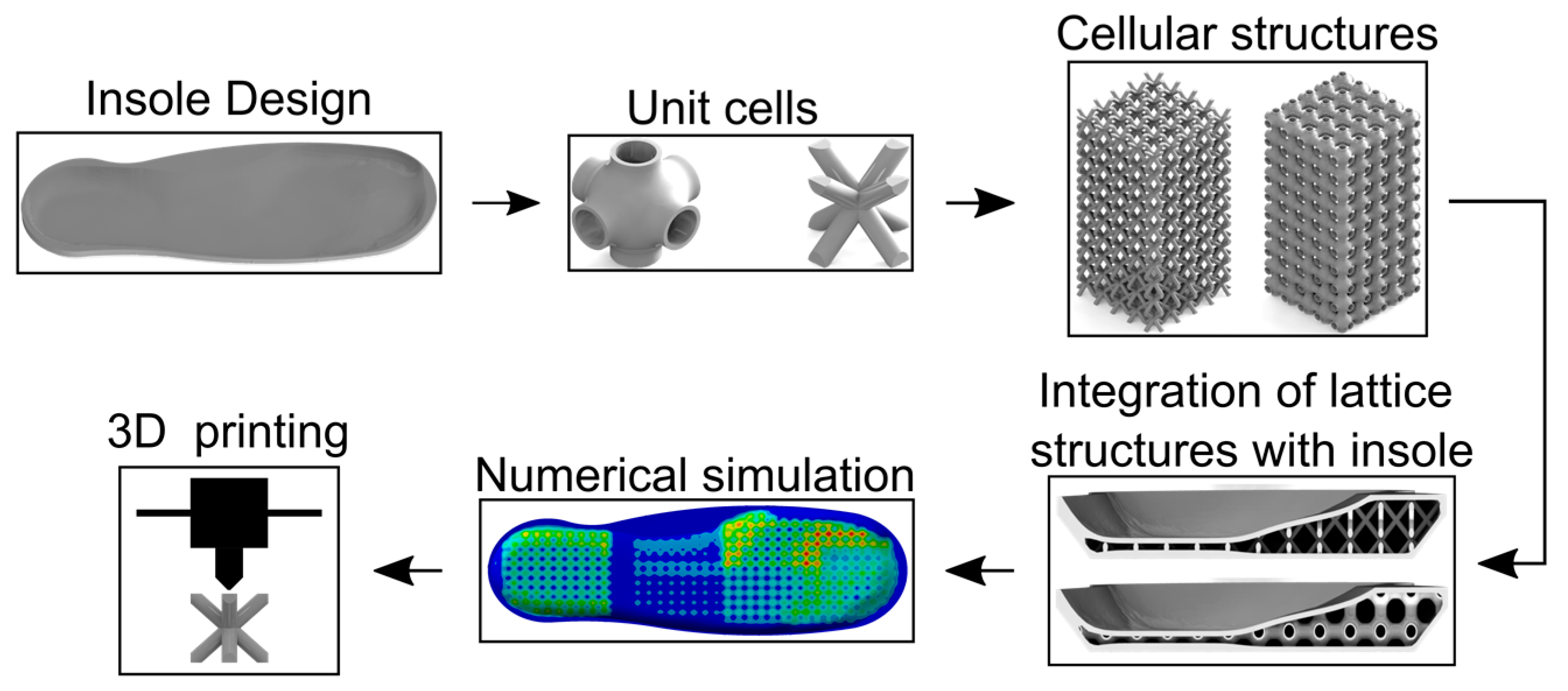
The complete methodology followed in this work is summarized in Figure 1. The design process of the cellular insoles started with the 3D scanning of the foot. Using computational design software, the cellular structures employed in the insole were modeled and integrated into the insole model. Finite element studies of the different cellular-insole models were carried out to characterize the deformation and Von Mises stresses under the applied pressures. Finally, cellular insoles were fabricated via AM using FFF.

Figure 1.
Study methodology: insole modeling, unit cells, cellular structure modeling, cellular structure integration, numerical simulation, and additive manufacturing.
2.1. Computational Insole Design
Insole modeling begins with a foot scan with a Sense® 3D scanner (3D Systems, Rock Hill, SC, USA). In the software Sense® V2.0, the initial repair of the model was carried out, eliminating the surfaces on the periphery of the model inherent to the scanning process; later, the model was refined in Meshmixer® (V3.5.474, Autodesk, Mill Valley, CA, USA) to generate a smooth surface. The digital model (STL file) is exported to the software Gensole® (Beta, Gyrobot, UK), where an insole is built according to the mesh-modifying parameters, e.g., length, significant and minor thickness. Finally, the STL file of the insole is exported to Solidworks® (v2020, Dassault Systèmes, Waltham, MA, USA), to incorporate the cellular structures with a periodic distribution in the internal part of the insole, as shown in Figure 2.
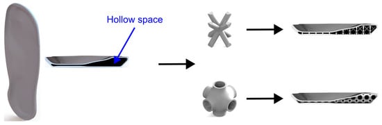
Figure 2.
Hollow insole and insole with cellular structure implemented.
2.2. Computational Design of Unit Cells and Characterization under Compressive Loading via Simulations of Cellular Structures
Depending on their deformation mechanism, cellular structures can be classified as stretch-dominated and bending-dominated. According to the Maxwell criterion [3], BCC is bending-dominated, and this structure is often used in energy absorption applications [24]. In contrast, some TPMS respond primarily by shortening or stretching of their constituent elements. This results in higher stiffness and strength when the TPMS structure is compared with bending-dominated topologies [25]. The nature of the deformation mechanisms of these two topologies brings an interesting comparison when these are employed in insoles.
To characterize the porosity–property relationship, three unit cells with different relative densities were proposed for each topology. In the BCC unit cell, the relative density was modified with the variation in the strut diameter, and in the TPMS, it was achieved with the change in the thickness of the walls. Figure 3 shows the dimensions for both topologies and the different relative densities. The cellular structures were built in Solidworks®, and were composed of a cuboid of 5 unit cells in the X- and Y-axes and 10 unit cells in the Z-axis (see Figure 3). The unit-cell size was defined by two features. First, its size considers the space allowed in the insole limited by medial midfoot and medial forefoot. Second, the resolution of the 3D printer machine, which was between and .
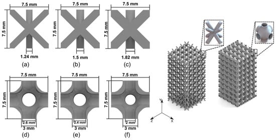
Figure 3.
Parameterization of unit cells. (Left) (a) BCC ; (b) BCC ; (c) BCC ; (d) TPMS ; (e) TPMS ; and (f) TPMS . (Right) 3D model of the cellular structure and unit cell.
All the models were subjected to compressive loading. Their relative density was calculated as the volume fraction , where is the overall volume of the cellular structure and is the volume of the actual space occupied by the cellular structure. The apparent elastic modulus was calculated by , where is the force applied to the structure, is the original length of the cell structure along the loading direction, is the apparent area (considering it as continuous and homogeneous, including voids) where the force is applied, and is the displacement of the cell structure due to the applied load.
The boundary conditions used to characterize the cellular structures via simulation are shown in Figure 4. All the models were meshed with quadratic tetrahedrons. To determine the element size used in the simulation, the solution time and precision of results of meshes with element sizes of , , and were evaluated. According to the results, elements were selected.
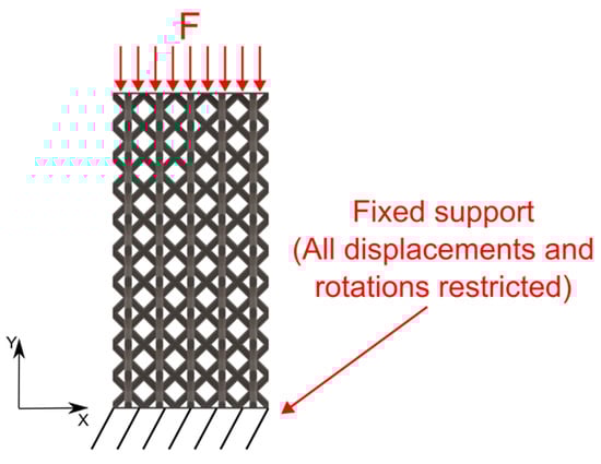
Figure 4.
Boundary conditions for the characterization of the cellular structures under compressive load F.
2.3. Numerical Simulation of the Insole under Compression
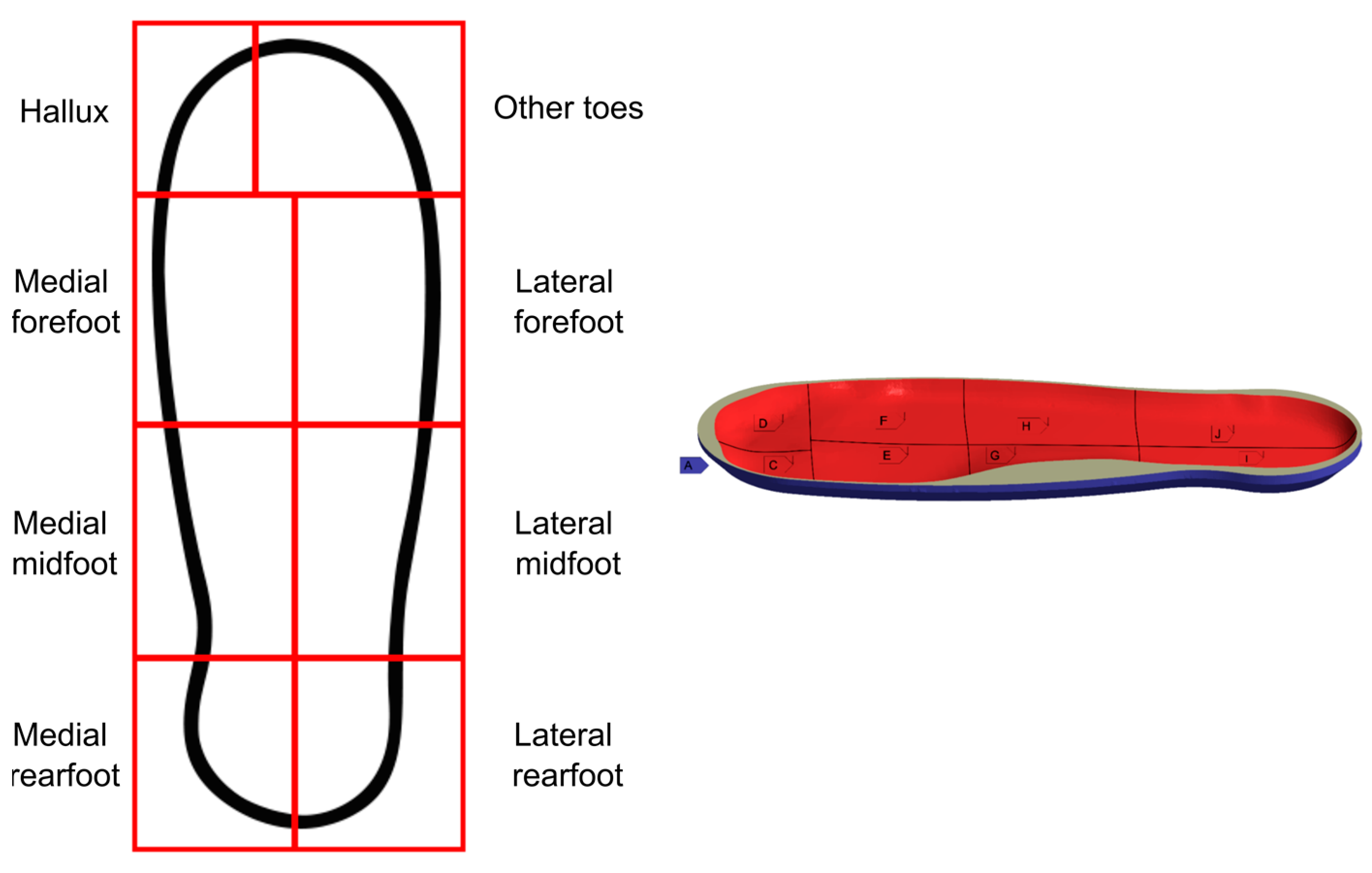
The loading conditions on the insoles were selected according to the zones where the foot is anatomically divided, as mentioned in [26] (see Figure 5). The zones proposed by Jonely et al. [26] were generated by dividing the foot longitudinally by drawing a line from distal to proximal between the first and second phalanx: the hallux area was defined by a rectangle enclosing the pressure zone observed under the hallux; the medial forefoot area was determined by a rectangle including the pressure zone observed under the first metatarsophalangeal joint, and bounding the hallux area proximally and the line dividing the first and second phalanx medially; the medial midfoot zone was bounded by a rectangle enclosing a longitudinal arch pressure zone medial to the line separating the first and second phalanges, and lateral to a line parallel to the medial edge of the medial forefoot zone; and the medial area of the rear foot was fixed from a rectangle enclosing a pressure zone under the calcaneus, which was medial to the line dividing the first and second phalanges, and lateral to a line parallel to the medial area of the midfoot. The pressures and boundary conditions were based on the loads proposed by Che et al. [27], as shown in Figure 5 and Table 1; the mechanical properties of TPU were obtained from [28] and are shown in Table 2.

Figure 5.
Boundary conditions applied in simulation. (Left) Split areas of the right foot are used for pressure placement. (Right) Boundary conditions according to Che et al. [27], including A Bottom area of the insole, C Hallux area, D Other toes area, E Medial forefoot area, F Lateral forefoot area, G Medial midfoot area, H Lateral midfoot area, I Medial rearfoot area, and J Lateral rearfoot area.

Table 1.
Applied pressures in the static simulation.
Table 2.
Mechanical properties of TPU material.
2.4. Additive Manufacturing of Insole Samples
Insole prototypes were manufactured via FFF using a Creality® 3D printer model CR-10. The digital models (STL files) were processed in Ultimaker Cura® v4.8.0 software, and TPU filament (Xpectro 3D®, China) was used as the raw material with a diameter of Figure 6 depicts the lamination process of the insole in the software and the 3D print process.
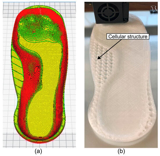
Figure 6.
Additive manufacturing of insoles via FFF. (a) Lamination process in software Ultimaker Cura® V4.8.0 and (b) 3D print process.
The rest of the printing parameters used are listed in Table 3. The nozzle size, layer height, and printing speed were non-constant printing parameters for the manufacture of the insoles with BCC and TPMS topology. Due to the thickness of the wall, it was necessary to use a nozzle to manufacture the insole with TPMS topology. For the BCC topology, it was necessary to decrease the printing speed to accurately form the unit-cell strut.
Table 3.
Printing parameters for insole manufacturing.
3. Results and Discussion
This section presents and discusses the effective mechanical properties characterized numerically for the cellular structures and the insoles, including simulation results of the insoles under the load conditions shown in Section 2.4. AM defects of the insole prototypes are also presented.
3.1. Mechanical Characterization of Cellular Structures and Insoles
This section includes the results of the computational characterization of the cellular structures and the insoles. The apparent Young´s modulus is presented and related to the structural behavior of the insoles that used cellular structures.
3.1.1. Insole Modeling and Apparent Compressive Stiffness via FEM for the Cellular Structures
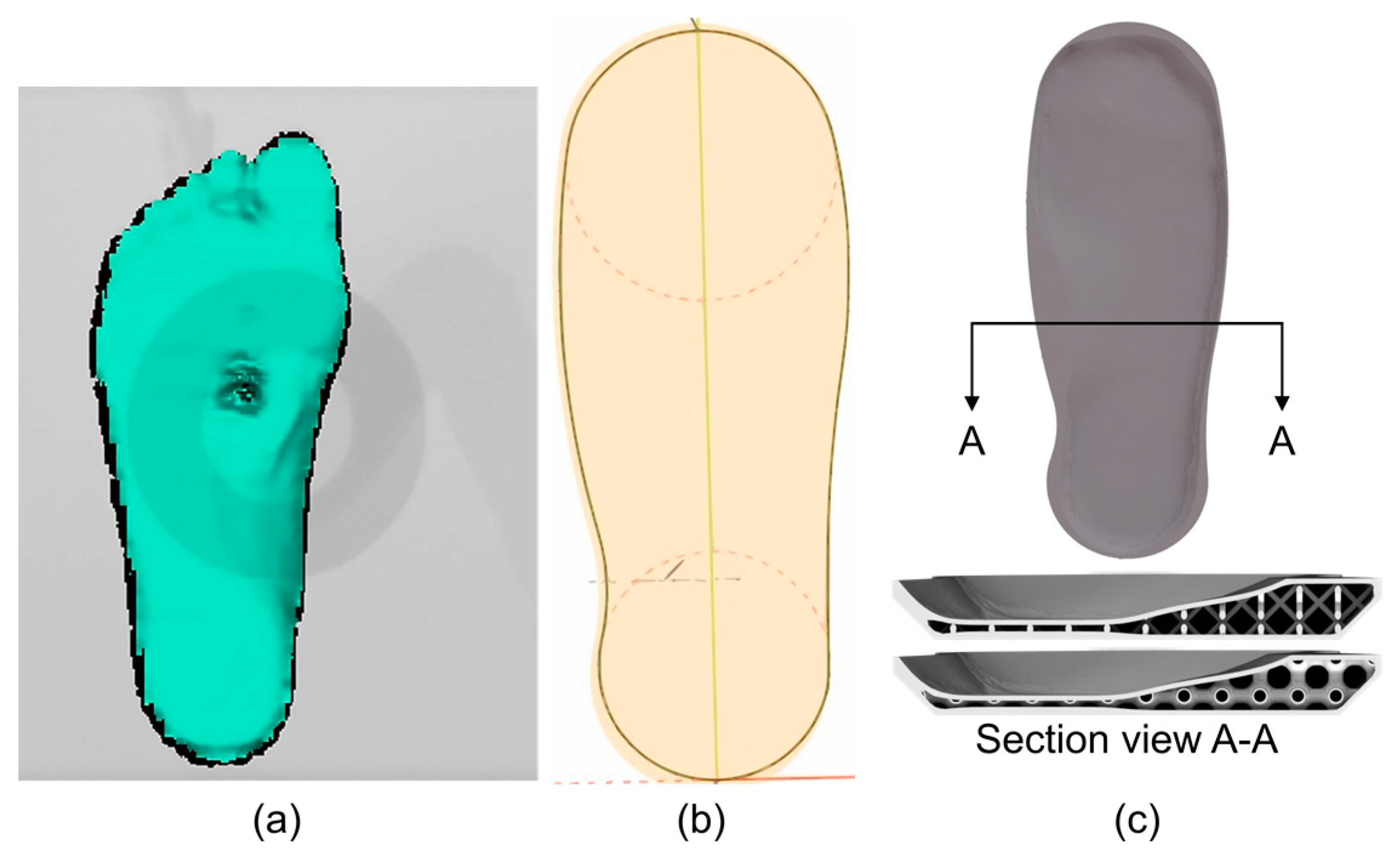
Figure 7a shows the surface obtained from the scanning process. The scanning process was performed on a person standing, of weight and height . The insole profile was obtained from the Gensole® software (see Figure 7b), where the insole profile was selected, and the top surface shape was generated from the surface obtained from the scanning process. Figure 7c shows the computational model of the insole; in the section view, the integration of the cellular structure in the internal part of the insole is displayed. Due to the thickness of the insole, the medial forefoot and medial midfoot areas were the only parts where the unit cells were fully integrated (there is no trim to fit the external geometry). In the thinnest part of the insole, the upper and lower surfaces were practically in contact; therefore, there were no unit cells in this area.
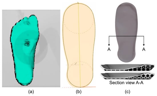
Figure 7.
Insole 3D modeling. (a) Scanning process, (b) profile of the insole, and (c) final insole model.
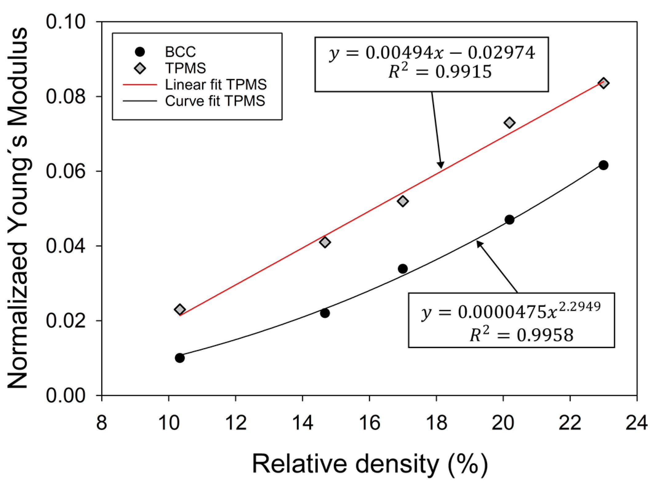
The apparent Young’s modulus () of the cellular structures was calculated using the displacement results obtained from the FE models under the compressive loads described in Section 2.2; these were then fed to the equation also described in Section 2.2 and normalized with the modulus of the constituent material (). The material properties used were listed in Table 2. The resulting apparent Young’s modulus and its relation to the corresponding relative density are summarized in Figure 8. Figure 9 includes the deformation of the structures; the structures with lower density have higher deformation.
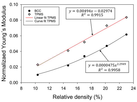
Figure 8.
Normalized apparent Young´s modulus for BCC and TPMS topologies to different relative densities.
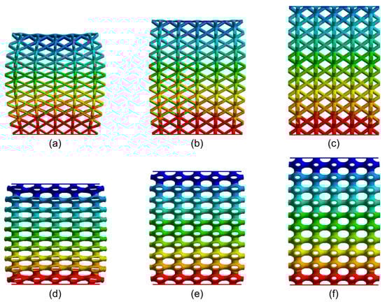
Figure 9.
Static simulation displacement results in cellular structure. (a) BCC 10.33%, (b) BCC 14.67%, (c) BCC 20.19%, (d) TPMS 10.33%, (e) TPMS 14.67%, and (f) TPMS 20.19%.
Figure 8 includes the stiffness–volume fraction results for both topologies studied. These types of curves enable the identification of the deformation mechanism by means of characterizing the scaling law that governs the property-volume fraction relationship [2]. For porous media, this relationship can be defined by the expression , where is a constant that depends on the cellular material topology, and is the scaling factor that takes a value for bending-dominated structures [29]. Note from the interpolation included in Figure 8 that the BCC structures show a scaling factor of , commonly obtained in other bending-dominated structures [1,9]. On the contrary, the primitive TPMS resulted in , commonly attributed to stretch-dominated topologies. Finally, for strut-based topologies, as the BCC, the Maxwell’s criterion can be applied to corroborate its deformation mechanism. Taking Maxwell’s criterion involves the calculation of the parameter using the expression , where is the number struts in the unit cell and is number the joints between struts. Now, if the topology is bending dominated; here the BCC unit cell has eight struts and nine joints; therefore, [30]. Additionally, note from Figure 9a–c that struts bent upon the application of the compressive load. On the other hand, in Figure 9d–f, the constituent elements shorten. These results are in agreement to previously reported data for BCC and primitive porous structures [8,31,32,33].
3.1.2. Deformation and Stress Analysis via FEM of Insoles
The comparison of the displacement and Von Mises stress results of the solid insole, with those of the BCC and TPMS cellular structures with different relative densities, are presented in Table 4.
Table 4.
Displacement and Von Mises stress resulting from simulation for the insole with BCC and TPMS topologies and different relative densities.
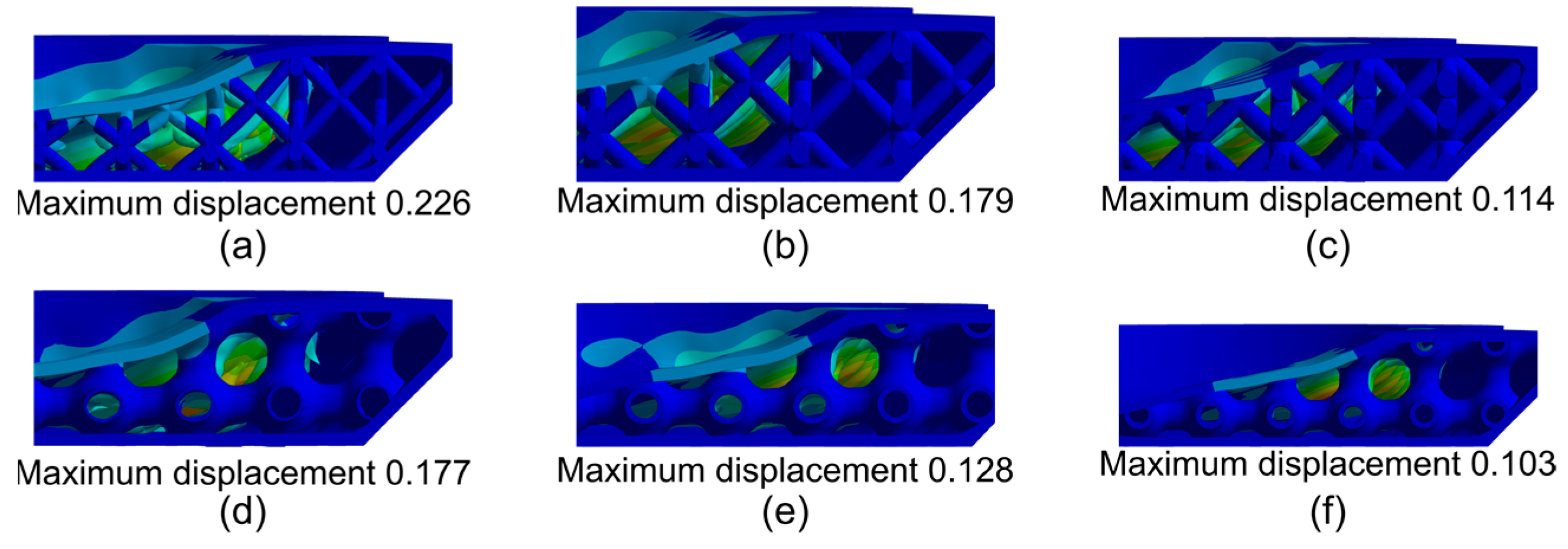
Figure 10 shows the local deformation of the cellular structure within the insole when applying the boundary conditions described in Section 2.3. Note in Figure 10 that the displacement of the BCC structures within the insole was higher than the TPMS structures; this result was related to the information presented in Figure 8, where it was shown that the BCC structure is more flexible than the TPMS structure.

Figure 10.
Static simulation displacement results in cellular structures in the insole: (a) insole with BCC cellular structure, 10.33%; (b) insole with BCC cellular structure, 14.67%; (c) insole with BCC cellular structure, 20.19%; (d) insole with TMPS cellular structure, 10.33%; (e) insole with TPMS cellular structure, 14.67%; and (f) insole with TPMS cellular structure, 20.19%.
Figure 10a–c show the displacement in the BCC structures with a relative density of , , and , respectively. Bending is observed in the unit-cell struts and a slight displacement of the unit cells to the right. Figure 10d–f show the displacement in the TPMS structures with a relative density of , , and , respectively. It can be seen that the unit cell tends to shorten as the circular feature of the TPMS unit cell is deformed (losing its circular form).
The displacement results are reported in Table 4. Note that the highest displacement in the insole resulted in the upper surface in all insole models. The upper surface of the insole deformed mostly over the voids formed by the cellular structure; this deformation was related to the geometry of the unit cell and not to the stiffness of the cellular structure. For example, the BCC structure has its struts at , forming a smaller gap between the unit cells compared to the TPMS structures; due to this, the maximum insole displacement is lower in the BCC structure than in the TPMS. Despite that, the BCC structure is still more flexible.
Figure 11a–c show maximum displacement in the hallux and medial forefoot areas. The upper surface of the insole was deformed in the gaps generated by the distribution of cellular structure in the internal part of the insole. The upper surface of the insole was in contact with the struts of the BCC structure when the insole was deformed. When these parts came into contact, the struts prevented further surface displacement.
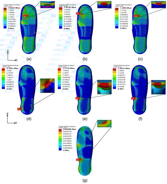
Figure 11.
Static simulation displacement results in cellular structures in the insole: (a) insole with BCC cellular structure, 10.33%; (b) insole with BCC cellular structure, 14.67%; (c) insole with BCC cellular structure, 20.19%; (d) insole with TMPS cellular structure, 10.33%; (e) insole with TPMS cellular structure, 14.67%; (f) insole with TPMS cellular structure, 20.19%; and (g) solid insole.
Figure 11d–f show maximum displacement in the medial midfoot and medial rearfoot areas. When the upper surface of the insole was deformed, contact of the deformed area with the walls of the TPMS unit cells occurred; therefore, even where the TPMS cellular had the highest compression stiffness, the insoles with TPMS cellular structure exhibited larger displacements due to the geometry of the unit cell. Figure 11g shows that the maximum displacement occurred on the solid insole in the medial forefoot and medial rear foot areas.
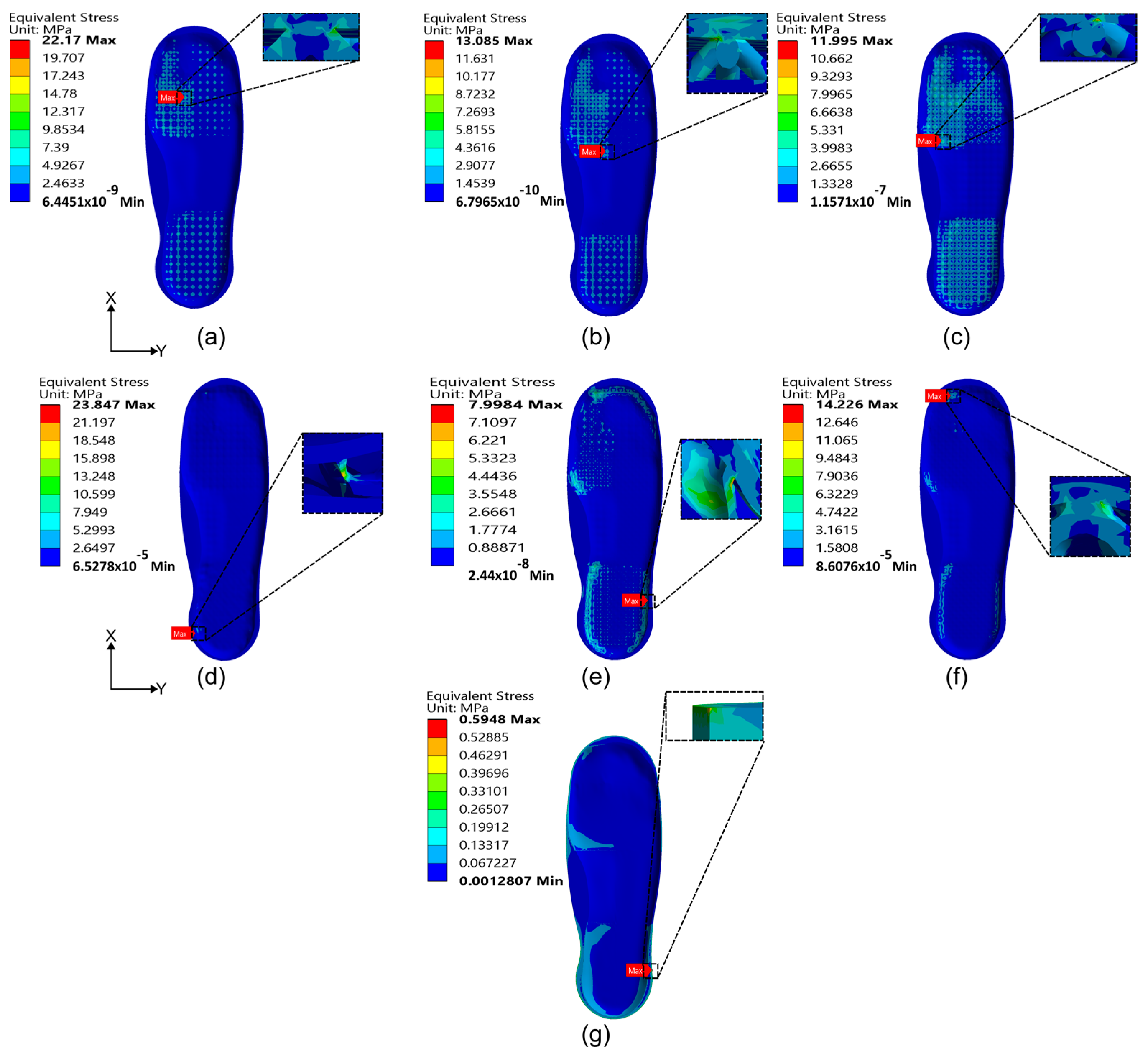
The maximum Von Mises stress in the insole with BCC cellular structure occurred in the medial forefoot (see Figure 12a–c), the stress was concentrated in the node of the unit cell, and the union of the top surface of the insole with the unit cell. In the insole with TPMS cellular structure with relative density, the stress was concentrated on the walls of the unit cells because the walls were thin, approximately (see Figure 12d). For the insoles shown in Figure 12e,f, the stress was concentrated in the union of the top surface of the insole with the unit cell. The walls in these insoles were thicker. Figure 12g shows that the stress was concentrated on the periphery of the insole near the lateral rear foot area.
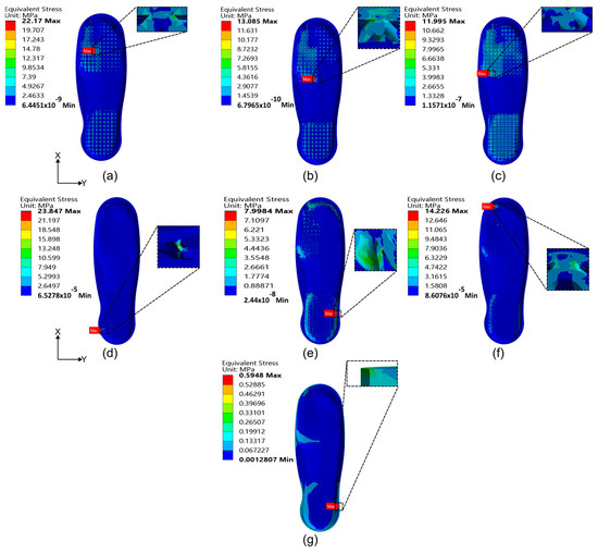
Figure 12.
Static simulation Von Mises stress results in an insole with cellular structures into the insole: (a) insole with BCC cellular structure, 10.33%; (b) insole with BCC cellular structure, 14.67%; (c) insole with BCC cellular structure, 20.19%; (d) insole with TMPS cellular structure, 10.33%; (e) insole with TPMS cellular structure, 14.67%; (f) insole with TPMS cellular structure, 20.19%; and (g) solid insole.
In the insoles with BCC cellular structure, the Von Mises stress increased as the relative density decreased. This effect occurred because the cellular structure with lower relative density had thinner struts in its unit cell. This resulted in a higher stress concentration between the top of the surface and the strut (see Figure 12a–c). The insoles that used TPMS cellular structure did not exhibit this tendency; the cellular structure with lower relative density had a stress concentration in the walls of the unit cells because they were thin (see Figure 12d). The other insoles with TPMS cellular structure concentrated the stress between the surface of the insole and the unit cell (see Figure 12e,f).
In light of a potential exposure to variable loading conditions, such as the those encountered when the person is walking or jogging, insoles must provide impact absorption. It has been shown that bending-dominated structures offer a more cushioning response that could benefit these conditions [34]. Hence, the topology that presents the bending-dominated deformation mechanism is the best option to be implemented in the insole, since it is the one that absorbs the highest energy.
According to Table 4, the insoles with the lowest displacement and Von Mises stress were the solid insole and the insole with the BCC cellular structure with relative density. The results of these models were compared with the insoles designed by Salles et al. [35], Rosas [36], and Ganesan et al. [37] in Table 5.
Table 5.
Comparison of simulation results with other works.
The solid insoles had stress concentrations lower than , the same as the models reported in [35,36,37] (see Table 5). The stress was concentrated on the periphery of the insole, near the area where the fixed support was placed. Furthermore, the stresses in the solid insole were evenly distributed over its entire surface (see Figure 12g). On the other hand, in the model with cellular structure, it is observed that the stress distribution was uneven; stress concentration was observed in regions of the cellular materials. The stress is concentrated at the joint of the struts of the unit cell with the surface of the insole and is transferred to the external part of the insole. Identifying stress concentrations in porous materials allows the designer to iterate between various topologies, while keeping the same volume fraction but targeting the region of the stress concentration.
The stress presented in these insoles does not exceed the elastic limit of the material. Therefore, under the conditions simulated, the implementation of cellular structures is feasible. On the other hand, the solid model proposed in the present work had stress levels similar to those reported by other authors [35,36,37] (see Table 5), indicating that the proposed model is satisfactory.
Table 5 shows that the insole made of solid TPU material showed and less deformation than those made of EVA and latex materials [36], respectively. These solid models also resulted in similar values for stiffness. In such solid or fully-filled models, any stiffness adjustment or tailoring can only be achieved through modifying the model design (geometry) or changing the base material. One advantage of implementing cellular structures in insoles is that their effective properties, e.g., stiffness, can be tuned by changing the topology or density of the structure, avoiding the modification of the geometry model of the insole or constituent material (see Table 4). Additionally, with the use of cellular structures, the deformation of the insole can be controlled, providing higher comfort to the person when walking or running.
The results listed in Table 4 and Table 5 show that a solid insole presents high levels of stiffness, while insoles with cellular structures tend to have higher deformation, that is, insoles with cellular structures can be useful for applications where energy absorption is sought and solid insoles are useful in applications where less flexible response is required.
3.2. Additive Manufacturing Results
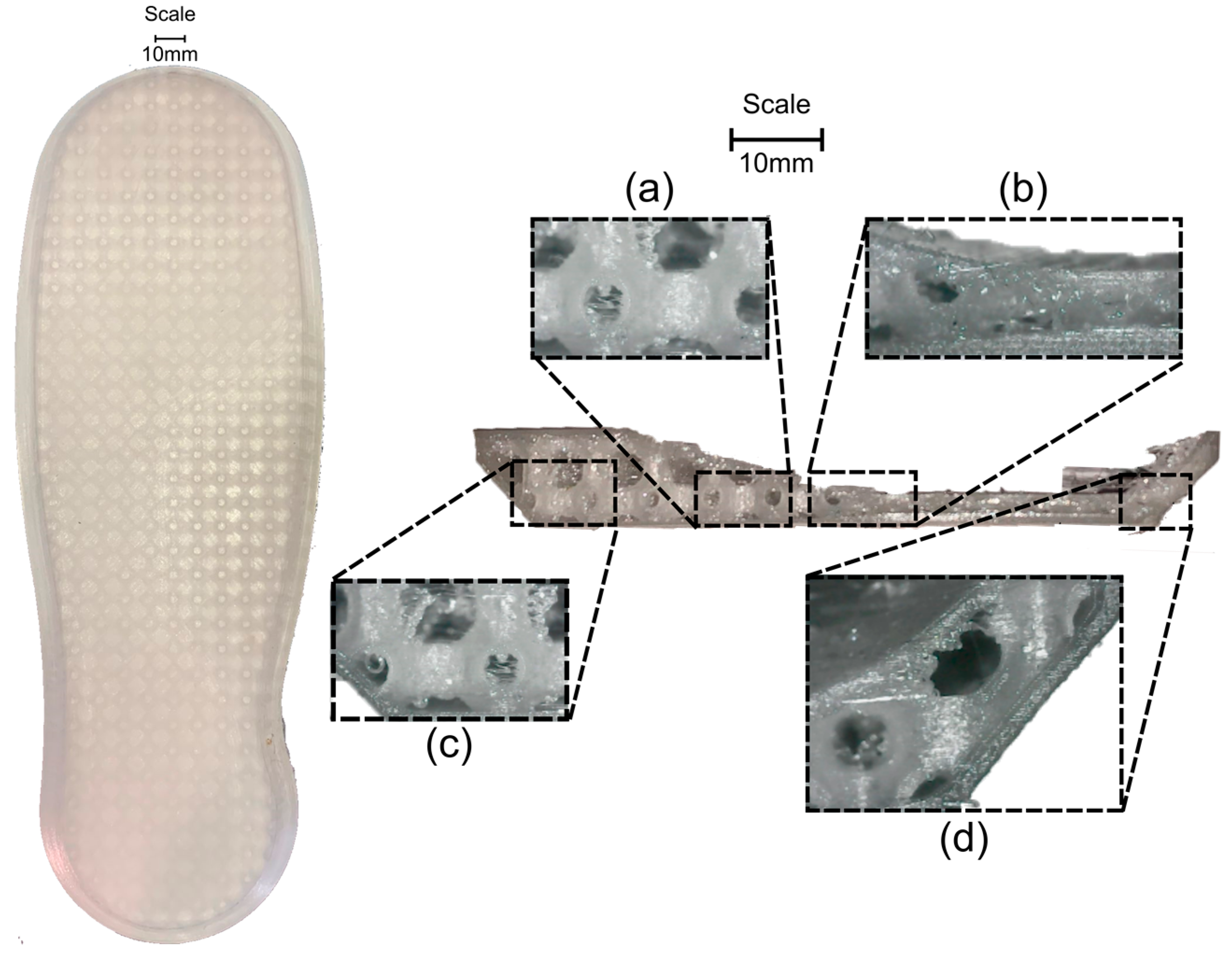
To visualize printing defects in the cellular structures incorporated in the internal part of the insole and calculate their printing time, the insole was manufactured with BCC and TPMS cellular structure with relative density (see Figure 13 and Figure 14, respectively). The printing time for the BCC cell structure was h, while, for the TPMS cell structure, it was h. The difference could be attributed to the fact that the insole with surface structure was fabricated with a layer height of because the geometry of the unit cell is more complex.
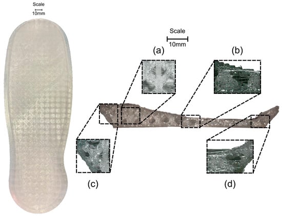
Figure 13.
Insole resulting from additive manufacturing by the FFF method. (Left) Insole with BCC cellular structure. (Right): Cross-section of the BCC cellular structure insole: (a) BCC cellular structure; (b) narrow zone; (c) arc periphery; (d) sloping periphery.
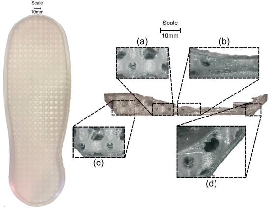
Figure 14.
Insole resulting from additive manufacturing by the FFF method. (Left) Insole with TPMS cellular structure. (Right) Cross-section of the TPMS cellular structure insole: (a) TPMS cellular structure; (b) narrow zone; (c) arc periphery; (d) sloping periphery.
A sectioned insole model was printed, as presented in Figure 13 and Figure 14, to observe the printing quality corresponding to the insoles with BCC and TPMS cellular structure, respectively. Selected areas were used for analysis. In Figure 13a, it can be observed that the joining between the BCC cells presented threads and that the size of the struts varies between unit cells. In contrast, in Figure 14a, a difference between the internal circumferences of the surface structure can be appreciated, presenting the “stair-stepping” effect, causing the curvatures not to be smooth. This effect is common in cellular structures manufactured via FFF. The authors of [38,39] analyzed the manufacture of various cellular structures and reported that all of them presented this effect regardless of the printing parameters, although the effect is more notable when the layer height is greater.
Comparing Figure 13a and Figure 14a, note that the layer height used in the printing process has a direct impact on the building of the unit cell. For instance, for the BCC topology with a layer height of was used and the constituent strut resulted in various diameter variations along their length. On the other hand, in the TPMS structure, a layer height of was implemented and the geometry of the cellular structure was formed with higher accuracy, except for a slight accumulation of excess material near the edges of the insole outer surface. The resulting variation in layer height between the models (and other defects) could affect both the accuracy of the building of the cellular topology and the stress concentration and distribution. Figure 13 and Figure 14 were obtained from intentionally designed sectioned insole models. These were designed and used for demonstration purposes, allowing visual inspection of the printing results at the inner zones of the insole.
Figure 13b and Figure 14b show where the unit cells were partially located. As the hollow of the insole area narrowed, the geometry presented more deformations while a quasi-solid area was generated. The areas shown in Figure 13c,d and Figure 14c,d show the contact between the unit cells and the periphery of the insole. There was complete contact between the surface and the unit cell because a periodic cellular structure was implemented; incomplete unit cells can be observed and, in the perimeter of the insole, there was an accumulation of material in the struts of the BCC cellular structure.
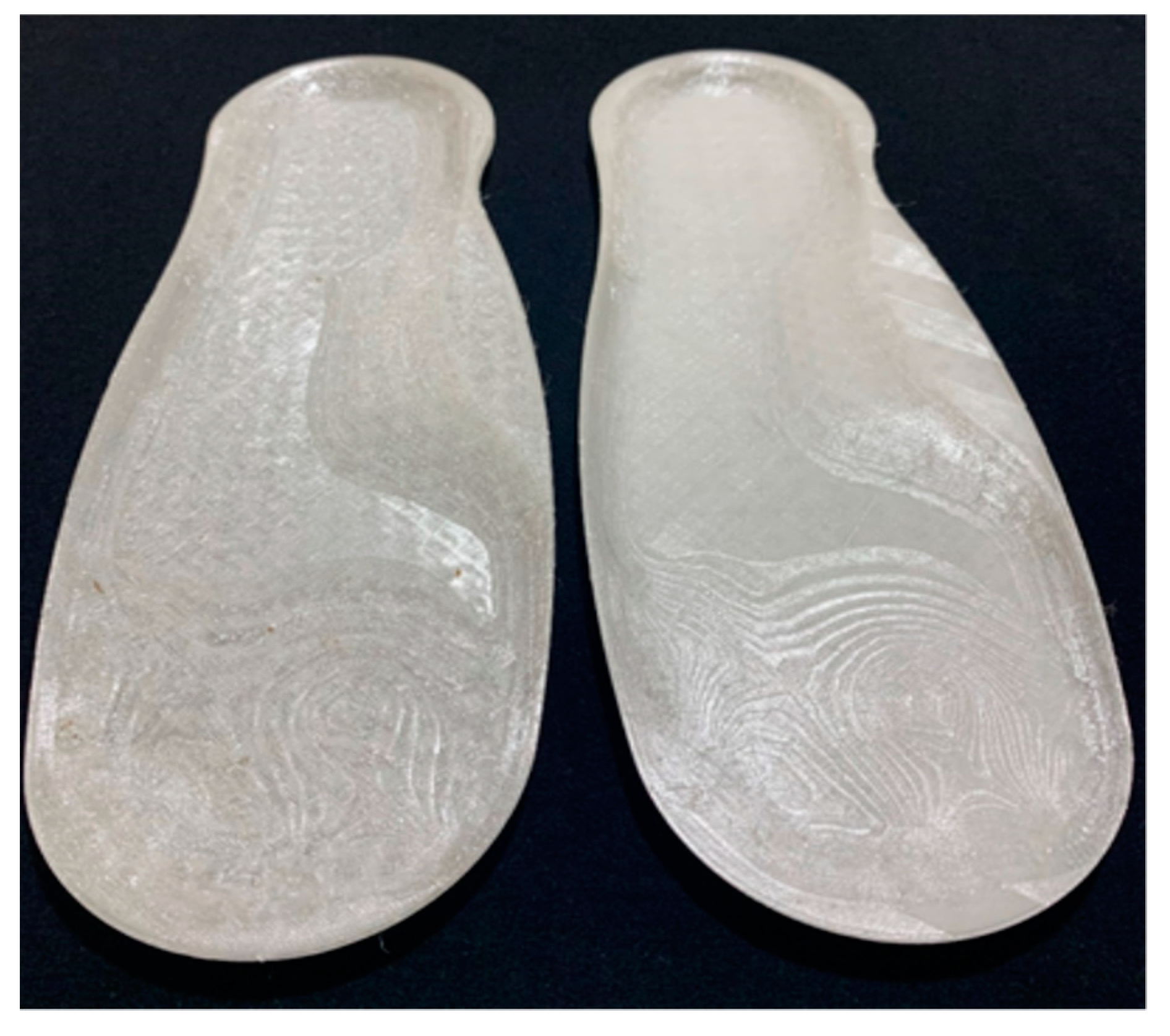
Employing FFF usually leaves burrs and barbs on the surfaces [40]. Figure 15 shows that the most affected surface areas presented as low quality as more irregularities in the design (toes and forefoot) can be observed, causing unwanted surface traces in the insole.

Figure 15.
Surface irregularities resulting from the fabrication of the insole.
4. Conclusions
In this work, insoles with cellular structures were designed and studied using 3D scanning and AM. The main conclusions obtained from this work were:
- A methodology for the manufacture of insoles was developed with the use of innovative tools such as 3D scanning and AM; it was shown that the model obtained from the 3D scan is functional for the creation of insoles, and the FFF method is a good alternative for manufacturing.
- Simulation results demonstrate that the insoles proposed in this work presented stresses and displacements similar to those reported in other works, applying pressures developed when a person is standing. This indicates that the solid insole model was adequate.
- The feasibility to adapt two cellular structures (BCC and TPMS) to the interior of the insoles was demonstrated; these insoles presented a higher displacement of their upper surface than the solid insoles due to the spaces generated between the unit cells of the cellular structure. The insole design that incorporated the BCC cellular structure had a lower displacement of its surface than the TPMS because the geometry of the unit cells prevented a higher displacement. It was observed that the displacement of the top surface of the insoles depends on the geometry of the unit cell and not on the rigidity of the cellular structure.
- The stiffness of the cellular structures was characterized via FEM, and the TPMS cell structure was stiffer than the BCC; however, the insoles that integrated the BCC cellular structure presented lower displacement due to the geometry of the cellular structure.
- Using cellular materials in the model could help enhance the performance of the insoles towards more personalized products. Different cellular topologies could be beneficial for different performance demands and results. Specifics of the intended use should be considered in order to select the cellular topology.
- Defects, such as the star-case effect obtained on the upper sections of the insoles could be reduced with the use of curved-layered FFF. This method has shown to be efficient for this purpose, while enhancing the mechanical properties of the fabricated part. This is achieved by ensuring raster continuity that conforms precisely to the targeted surface.
- The results of the static simulation showed that the topologies and models proposed here showed promising performances. However, insoles could also be exposed to high frequency loading scenarios (especially for sport users). Therefore, future research should focus on understanding and characterizing the dynamic response to such structures. For dynamic loading scenarios, surface-based structures have shown better performance as they reduce stress concentrators [10,41].
- Concerning the development of personalized products, functionally graded structures offer a solution to very specific desired responses. Preliminary tests and scans showed areas with higher pressure concentrations; depending on the desired performance, these could be filled with specific topologies or volume fractions, while, in other less demanding regions, alternatives could be explored.
With the methodology used in this work, the fabrication of a functional insole was achieved, and the use of technologies (3D scanning and AM) can help to reduce the manufacturing time and costs of the insole, being a viable alternative for its fabrication. This work presented a preliminary study on the validation of the computational design in static conditions using FEM. Therefore, to complement the validation of the design and manufacturing of the insole, future work should characterize the properties under dynamic loading conditions of the 3D printed insoles. This will allow the evaluation of their performance under loading conditions produced in the gait cycle while considering the possible printing defects inherent to the FFF process.
Author Contributions
Conceptualization, G.R.-B. and E.C.-U.; methodology, G.R.-B.; formal analysis, G.R.-B. and E.C.-U.; investigation, G.R.-B. and E.C.-U.; resources, K.A.C.-G. and L.A.M.-H.; data curation, L.A.M.-H.; writing—original draft preparation, G.R.-B.; writing—review and editing, E.C.-U., G.I.P.-S. and K.A.C.-G.; visualization, G.R.-B.; supervision, G.I.P.-S. and K.A.C.-G.; project administration, K.A.C.-G. All authors have read and agreed to the published version of the manuscript.
Funding
Support from the Mexican Humanities, Sciences and Technologies (CONAHCyT) for Ph.D. studies of the first author (grant number 735037).
Institutional Review Board Statement
Not applicable.
Informed Consent Statement
Not applicable.
Data Availability Statement
All data generated and analyzed in this article are included within the article.
Conflicts of Interest
The authors declare no conflict of interest.
References
- Tancogne-Dejean, T.; Mohr, D. Stiffness and Specific Energy Absorption of Additively-Manufactured Metallic BCC Metamaterials Composed of Tapered Beams. Int. J. Mech. Sci. 2018, 141, 101–116. [Google Scholar] [CrossRef]
- Lakes, R.S. Cellular Solids. J. Biomech. 1989, 22, 397. [Google Scholar] [CrossRef]
- Bhate, D.; Penick, C.A.; Ferry, L.A.; Lee, C. Classification and Selection of Cellular Materials in Mechanical Design: Engineering and Biomimetic Approaches. Designs 2019, 3, 19. [Google Scholar] [CrossRef]
- Gibson, L.J. Biomechanics of Cellular Solids. J. Biomech. 2005, 38, 377–399. [Google Scholar] [CrossRef] [PubMed]
- Surjadi, J.U.; Gao, L.; Du, H.; Li, X.; Xiong, X.; Fang, N.X.; Lu, Y. Mechanical Metamaterials and Their Engineering Applications. Adv. Eng. Mater. 2019, 21, 800864. [Google Scholar] [CrossRef]
- Bhate, D. Four Questions in Cellular Material Design. Materials 2019, 12, 1060. [Google Scholar] [CrossRef] [PubMed]
- Ushijima, K.; Cantwell, W.J.; Mines, R.A.W.; Tsopanos, S.; Smith, M. An Investigation into the Compressive Properties of Stainless Steel Micro-Lattice Structures. J. Sandw. Struct. Mater. 2011, 13, 303–329. [Google Scholar] [CrossRef]
- Liu, Y.; Dong, Z.; Ge, J.; Lin, X.; Liang, J. Stiffness Design of a Multilayer Arbitrary BCC Lattice Structure with Face Sheets. Compos. Struct. 2019, 230, 111485. [Google Scholar] [CrossRef]
- Zhao, M.; Liu, F.; Fu, G.; Zhang, D.Z.; Zhang, T.; Zhou, H. Improved Mechanical Properties and Energy Absorption of BCC Lattice Structures with Triply Periodic Minimal Surfaces Fabricated by SLM. Materials 2018, 11, 2411. [Google Scholar] [CrossRef]
- Benedetti, M.; du Plessis, A.; Ritchie, R.O.; Dallago, M.; Razavi, S.M.J.; Berto, F. Architected Cellular Materials: A Review on Their Mechanical Properties towards Fatigue-Tolerant Design and Fabrication. Mater. Sci. Eng. R Rep. 2021, 144, 100606. [Google Scholar] [CrossRef]
- Kapfer, S.C.; Hyde, S.T.; Mecke, K.; Arns, C.H.; Schröder-Turk, G.E. Minimal Surface Scaffold Designs for Tissue Engineering. Biomaterials 2011, 32, 6875–6882. [Google Scholar] [CrossRef] [PubMed]
- Limmahakhun, S.; Oloyede, A.; Sitthiseripratip, K.; Xiao, Y.; Yan, C. 3D-Printed Cellular Structures for Bone Biomimetic Implants. Addit. Manuf. 2017, 15, 93–101. [Google Scholar] [CrossRef]
- Wang, H.V.; Johnston, S.R.; Rosen, D.W. Design of a Graded Cellular Structure for an Acetabular Hip Replacement Component. In Proceedings of the 17th International Solid Freeform Fabrication Symposium, Austin, TX, USA, 14–16 August 2006; pp. 111–123. [Google Scholar]
- Alkhatib, S.E.; Tarlochan, F.; Mehboob, H.; Singh, R.; Kadirgama, K.; Harun, W.S.B.W. Finite Element Study of Functionally Graded Porous Femoral Stems Incorporating Body-Centered Cubic Structure. Artif. Organs 2019, 43, E152–E164. [Google Scholar] [CrossRef] [PubMed]
- Mandolini Aya AlAjjan, M.; Iqbal Mohammed, M. 3D Printable Insole with TPMS Lattice for Relieving Foot Plantar Pressure and Shear Forces. Master’s Thesis, Faculty of Engineering, Università Politecnica delle Marche, Rome, Italy, 2022. [Google Scholar]
- Moeini, M.; Ménard, A.L.; Yue, L.; Hajizadeh, M.; Begon, M.; Lévesque, M. Computationally Efficient Model to Predict the Deformations of a Cellular Foot Orthotic. Comput. Biol. Med. 2022, 146, 105532. [Google Scholar] [CrossRef] [PubMed]
- Ha, C.S.; Yao, D.; Xu, Z.; Liu, C.; Liu, H.; Elkins, D.; Kile, M.; Deshpande, V.; Kong, Z.; Bauchy, M.; et al. Rapid Inverse Design of Metamaterials Based on Prescribed Mechanical Behavior through Machine Learning. Nat. Commun. 2023, 14, 5765. [Google Scholar] [CrossRef] [PubMed]
- Zolfagharian, A.; Lakhi, M.; Ranjbar, S.; Bodaghi, M. Custom Shoe Sole Design and Modeling toward 3D Printing. Int. J. Bioprint. 2021, 7, 396. [Google Scholar] [CrossRef]
- Su, H.; Mo, Z.; Guo, J.; Fan, Y. Corrigendum to “The Effect of Arch Height and Material Hardness of Personalized Insole on Correction and Tissues of Flatfoot”. J. Healthc. Eng. 2018, 2018, 4136246. [Google Scholar] [CrossRef]
- Amorim, D.J.N.; Nachtigall, T.; Alonso, M.B. Exploring Mechanical Meta-Material Structures through Personalised Shoe Sole Design. In Proceedings of the 3rd Annual ACM Symposium on Computational Fabrication, Pittsburgh, PA, USA, 16–18 June 2019. [Google Scholar] [CrossRef]
- Janisse, D.J. A Scientific Approach to Insole Design for the Diabetic Foot. Foot 1993, 3, 105–108. [Google Scholar] [CrossRef]
- Salles, A.S.; Gyi, D.E. The Specification of Personalised Insoles Using Additive Manufacturing. Work 2012, 41, 1771–1774. [Google Scholar] [CrossRef]
- Hu, C.W.; Nguyen, C.T.; Hölbling, D.; Pang, T.Y.; Baca, A.; Dabnichki, P. A Novel 3D Printed Personalised Insole for Improvement of Flat Foot Arch Compression and Recoil—Preliminary Study. Proc. Inst. Mech. Eng. Part L J. Mater. Des. Appl. 2022, 237, 329–342. [Google Scholar] [CrossRef]
- Bai, L.; Yi, C.; Chen, X.; Sun, Y.; Zhang, J. Effective Design of the Graded Strut of BCC Lattice Structure for Improving Mechanical Properties. Materials 2019, 12, 2192. [Google Scholar] [CrossRef] [PubMed]
- Simsek, U.; Akbulut, A.; Gayir, C.E.; Basaran, C.; Sendur, P. Modal Characterization of Additively Manufactured TPMS Structures: Comparison between Different Modeling Methods. Int. J. Adv. Manuf. Technol. 2021, 115, 657–674. [Google Scholar] [CrossRef]
- Jonely, H.; Brismée, J.M.; Sizer, P.S.; James, C.R. Relationships between Clinical Measures of Static Foot Posture and Plantar Pressure during Static Standing and Walking. Clin. Biomech. 2011, 26, 873–879. [Google Scholar] [CrossRef] [PubMed]
- Che, H.; Nigg, B.M.; de Koning, J. Relationship between Plantar Pressure Distribution under the Foot and Insole Comfort. Clin. Biomech. 1994, 9, 335–341. [Google Scholar] [CrossRef]
- Qi, H.J.; Boyce, M.C. Stress-Strain Behavior of Thermoplastic Polyurethanes. Mech. Mater. 2005, 37, 817–839. [Google Scholar] [CrossRef]
- Cuan-Urquizo, E.; Shalchy, F.; Bhaskar, A. Compressive Stiffness of Staggered Woodpile Lattices: Mechanics, Measurement, and Scaling Laws. Int. J. Mech. Sci. 2020, 187, 105932. [Google Scholar] [CrossRef]
- Austermann, J.; Redmann, A.J.; Dahmen, V.; Quintanilla, A.L.; Mecham, S.J.; Osswald, T.A. Fiber-Reinforced Composite Sandwich Structures by Co-Curing with Additive Manufactured Epoxy Lattices. J. Compos. Sci. 2019, 3, 53. [Google Scholar] [CrossRef]
- Jia, H.; Lei, H.; Wang, P.; Meng, J.; Li, C.; Zhou, H.; Zhang, X.; Fang, D. An Experimental and Numerical Investigation of Compressive Response of Designed Schwarz Primitive Triply Periodic Minimal Surface with Non-Uniform Shell Thickness. Extrem. Mech. Lett. 2020, 37, 100671. [Google Scholar] [CrossRef]
- Balabanov, S.V.; Makogon, A.I.; Sychev, M.M.; Evstratov, A.A.; Regazzi, A.; Lopez-Cuesta, J.M. 3D Printing and Mechanical Properties of Polyamide Products with Schwartz Primitive Topology. Tech. Phys. 2020, 65, 211–215. [Google Scholar] [CrossRef]
- Dar, U.A.; Mian, H.H.; Abid, M.; Topa, A.; Sheikh, M.Z.; Bilal, M. Experimental and Numerical Investigation of Compressive Behavior of Lattice Structures Manufactured through Projection Micro Stereolithography. Mater. Today Commun. 2020, 25, 101563. [Google Scholar] [CrossRef]
- Jin, N.; Wang, F.; Wang, Y.; Zhang, B.; Cheng, H.; Zhang, H. Failure and Energy Absorption Characteristics of Four Lattice Structures under Dynamic Loading. Mater. Des. 2019, 169, 107655. [Google Scholar] [CrossRef]
- Salles, A.S.; Gyi, D.E. Delivering Personalised Insoles to the High Street Using Additive Manufacturing. Int. J. Comput. Integr. Manuf. 2013, 26, 386–400. [Google Scholar] [CrossRef]
- Rosas, A. Diseño de Una Plantilla Ergonómica Que Regule La Presión Plantar En Jóvenes Practicantes de Baloncesto Femenil: Análisis Biomecánico y de Elemento Finito; CIATEC: Tallin, Estonia, 2021. [Google Scholar]
- Ganesan, S.; Ranganathan, R. Design and Development of Customised Split Insole Using Additive Manufacturing Technique. Int. J. Rapid Manuf. 2018, 7, 295. [Google Scholar] [CrossRef]
- Guerra Silva, R.; Torres, M.J.; Zahr Vinuela, J.; Zamora, A.G. Manufacturing and Characterization of 3D Polymer Lattice Structures Using Fused Filament Fabrication. Polymers 2021, 13, 635. [Google Scholar] [CrossRef]
- Karamooz Ravari, M.R.; Kadkhodaei, M.; Badrossamay, M.; Rezaei, R. Numerical Investigation on Mechanical Properties of Cellular Lattice Structures Fabricated by Fused Deposition Modeling. Int. J. Mech. Sci. 2014, 88, 154–161. [Google Scholar] [CrossRef]
- Cendrero, A.M.; Fortunato, G.M.; Munoz-Guijosa, J.M.; De Maria, C.; Lantada, A.D. Benefits of Non-Planar Printing Strategies towards Eco-Efficient 3d Printing. Sustainability 2021, 13, 1599. [Google Scholar] [CrossRef]
- García-Ávila, J.; Cuan-Urquizo, E.; Ramírez-Cedillo, E.; Rodríguez, C.A.; Vargas-Martínez, A. Novel Porous Structures with Non-Cubic Symmetry: Synthesis, Elastic Anisotropy, and Fatigue Life Behavior. Math. Mech. Solids 2023, 28, 943–972. [Google Scholar] [CrossRef]


Disclaimer/Publisher’s Note: The statements, opinions and data contained in all publications are solely those of the individual author(s) and contributor(s) and not of MDPI and/or the editor(s). MDPI and/or the editor(s) disclaim responsibility for any injury to people or property resulting from any ideas, methods, instructions or products referred to in the content. |
© 2023 by the authors. Licensee MDPI, Basel, Switzerland. This article is an open access article distributed under the terms and conditions of the Creative Commons Attribution (CC BY) license (https://creativecommons.org/licenses/by/4.0/).