Article

Influence of Hot Isostatic Pressing on Microstructure and Tensile Properties of Nickel-Free Stainless Steel for Metal Binder Jetting

1
Institute of Applied Powder Metallurgy and Ceramics at RWTH Aachen e.V. (IAPK), 52062 Aachen, Germany
2
Institute for Materials Applications in Mechanical Engineering (IWM), RWTH Aachen University, 52062 Aachen, Germany
3
GKN Powder Metallurgy Engineering GmbH, 53177 Bonn, Germany
*
Author to whom correspondence should be addressed.
Appl. Sci. 2023, 13(23), 12676; https://doi.org/10.3390/app132312676
Submission received: 27 September 2023 / Revised: 2 November 2023 / Accepted: 15 November 2023 / Published: 26 November 2023
(This article belongs to the Section Additive Manufacturing Technologies)

Abstract

:

Featured Application

Highly complex jewelry, watches and medical instruments with skin contact to avoid nickel allergies.

Abstract

Additive manufacturing processes continue to grow in popularity. Hereby, metal binder jetting (MBJ) has a high potential for series production of highly complex parts with added value compared to other production technologies. Applications already exist in thermal management, filtering, or fluid distribution. As with beam-based additive manufacturing processes, the materials available for MBJ are still limited. Especially in the area of nickel-free stainless steels; for example, for medical applications, there are hardly any options available. Therefore, this study investigates a newly developed nickel-free stainless steel specifically designed for the MBJ process. Particular attention is paid to the microstructure and the mechanical properties such as hardness and tensile strength. In addition, the investigation focuses on the potential of hot isostatic pressing (HIP) after sintering to favorably influence the microstructure and the mechanical properties. The results show that in the as-sintered state, a maximum porosity of 2.8% is present, which can be completely removed by hot isostatic post-densification. HIP post-densification improves both the yield strength and the tensile strength by about 10%. The increase in elongation at break is around 50%.

1. Introduction

Metal binder jetting (MBJ) is a powder bed-based additive manufacturing (AM) process in which metal powder is deposited layer by layer onto a build platform. An organic binder is selectively injected into this powder bed within a predetermined geometry. This is followed by thermal curing of the binder, depowdering, debinding, and sintering. During sintering, the MBJ green bodies are consolidated, which is accompanied by a linear shrinkage of about 15–20% [1,2,3]. Sometimes, anisotropic shrinkage behavior is reported [4,5], which could be attributed to the layered structure and a not-optimally adjusted binder saturation [1,6]. MBJ components can already be found in many applications in aerospace, energy, and automotive sectors [7,8,9,10]. Compared to beam-based AM technologies, such as powder bed fusion with laser beam (PBF-LB) or electron beam (PBF-EB), the MBJ process offers several advantages: low residual stresses since no high temperature gradients occur in the process, a significantly reduced need for support structures, and easy up-scaling of the process for larger production quantities due to high build-up rates of more than 2000 cm3/h.
However, achieving almost complete densification during sintering is still a challenge, and MBJ components often have lower mechanical properties than conventionally manufactured parts due to their residual porosity [11]. This is known from other sinter-based technologies such as metal injection molding (MIM) or powder compaction. While these drawbacks limit the range of application, they can be overcome to a certain extent by post-treatment with hot isostatic pressing (HIP) [12,13].
HIP is a widely established manufacturing process in powder metallurgy, in which powder materials enclosed in a metallic capsule are consolidated to absolute density by the simultaneous application of high pressure and high temperatures [14]. In addition, HIP is very commonly used to post-densify components that may exhibit process-induced pores and defects, as is often the case with cast components. Highly loaded safety-relevant components are HIP post-densified by standard. One example are turbine blades for aircraft engines. Additionally, for materials produced by AM processes such as laser powder bed fusion (PBF-LB), HIP post-densification can provide remarkable improvement in reliability and mechanical properties [15,16,17,18,19]. To achieve densification without encapsulating the materials in the HIP process, no open porosity is permitted in the component, as the applied gas pressure would also act within the pores and these could not be closed. Only inner pores and thus a closed porosity can be densified. At a so called critical density, pore closure appears during sintering, which means that pores are no longer interconnected. According to theoretical models and experimental verifications, the critical density ranges from 89 to 94% [20]. The residual porosity of components produced by MBJ is exactly in this range between open and closed porosity and known to scatter locally [21]. Therefore, a high sinter density and a residual porosity not connected to the surface are highly important for achieving successful HIP densification of MBJ parts.
Even though additive manufacturing has come a long way in recent years, the materials available are still limited. For conventional manufacturing using subtractive processes, there are well over 2000 different types of steel; in additive manufacturing, the range of commercially available steels for AM processes is much smaller. Within the portfolio of the common AM machine manufacturers, the average number of qualified materials offered for the PBF-LB and MBJ processes is around 30, of which, between 12 and 14 are steel grades. One reason could be that many materials are not directly suitable for the AM process because, for example, they tend to crack in laser-based additive manufacturing or have poor sintering properties in sinter-based additive manufacturing. A review article from the year 2020 lists only 10 materials processed with MBJ that could be sintered to relative densities above 90% by that time [22]. Often, individual material adaptations are necessary. Several materials with good sintering properties are known from metal injection molding (MIM), but MIM powder is usually finer than the powder used in the MBJ process, thus both are not directly comparable. Next to Co-Cr alloys, Cu alloys, Ni-based alloys, WC-Co, and Ti6Al4V, the most commonly used steels in the MBJ process are 316L [3,23,24], 304L [22,25], 17-4PH [13,26,27], 420 [22,28], and H13 [29].
However, when it comes to medical applications, where AM can particularly offer the major advantage of customized parts, there is limited availability of possible materials and, to the best of the authors’ knowledge, the only material investigated in the literature in the field of nickel-free stainless steel for binder jetting is the material used in this study [30]. Since other stainless steels, such as 316 L, contain high amounts of nickel, they are of limited use for medical applications, jewelry, and watches. Nickel can trigger allergies and cause undesirable reactions in connection with the human body. However, nickel is also an important element for ductility in stainless steel as it acts as an austenite stabilizer. Several approaches in literature describe how nickel-free stainless steels can achieve the desirable properties by adding nitrogen, which also stabilizes the austenite [31]. In powder metallurgy, there are already developments regarding nickel-free stainless steels for MIM [30,32,33].
In summary, by reviewing the existing literature, it can be stated that the range of materials for additive manufacturing is limited so far. In particular, special materials such as Ni-free steels for medical applications are limited. One reason in the MBJ area is that many conventional materials are not designed for additive manufacturing, and in the binder jetting area, are lacking in good sintering properties. As a result, residual porosity remains in the material, which reduces the mechanical properties. One way of improving the properties is hot isostatic post-densification with HIP.
The present study investigates the microstructure and mechanical properties of a newly developed high-nitrogen nickel-free stainless steel produced by MBJ. A particular focus is on the question of the extent to which subsequent heat treatment via hot isostatic pressing (HIP) can close the remaining residual porosity in the material and whether this is accompanied by an improvement in the mechanical properties, such as hardness and tensile strength and elongation at fracture.

2. Materials and Methods
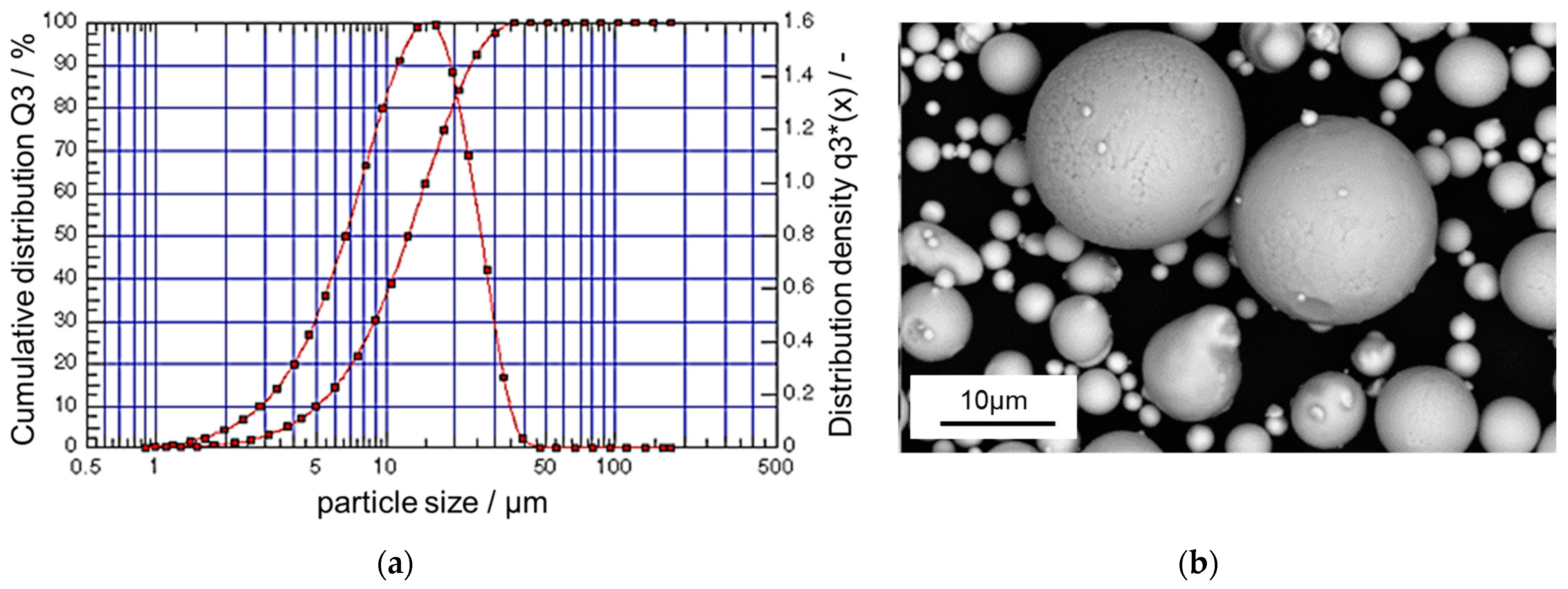
2.1. Material

The material used in this study is a novel, gas-atomized, non-magnetic, and nickel-free stainless steel (Ancor AM Ni-free SS, X15CrMnMoNi17-11-3), supplied by GKN Hoeganaes Corporation (Cinnaminson, NJ, USA). A scanning electron microscopy (SEM) image of the powder as well as the measured particle size distribution are shown in Figure 1.
The material is specially designed for printing with MBJ technologies by using a small particle size fraction (particle diameter 10–25 µm) to increase the sintering activity. The chemical composition is given in Table 1.
Since the material is nickel-free, the amount of nitrogen (0.349 wt.-%) and manganese (11.52 wt.-%) is increased to stabilize the fcc-phase. It is expected that additional nitrogen must be absorbed during sintering or further heat treatment to fully stabilize the fcc-phase. Cr, Ni, Mo, and Mn were measured by ICP-OES, and C, O, and N measurements were conducted by the combustion method.
Due to the high Cr, N, and Mo contents, this alloy achieves a pitting resistance equivalent number (PREN) of 33.6, which indicates high corrosion resistance.
Equilibrium calculations were performed using Thermo-Calc software 2021b (Thermo-Calc Software, Stockholm, Sweden) and the TCFE9 database [34]. The resulting phase fractions were discussed with respect to the sinter and HIP temperatures.

2.2. Binder Jetting Processing

An HP Metal Jet (HP Inc., Palo Alto, CA, USA) was used for 3D printing of tensile specimens. The following critical printing parameters were investigated within the printing process development for Ni-free stainless steel at GKN Additive and were kept constant for this study: recoater parameters (roller speed and rotation), layer thickness, printing temperature, and curing properties (temperature and time).

2.3. Sintering and Post-Processing

Debinding and sintering were conducted in a vacuum batch sintering furnace MIM-Vac Series (Centorr Vacuum Industries, Nashua, NH, USA) under a 100% N2-atmosphere at a sintering temperature of 1270 °C. Uncontrolled furnace cooling with an average cooling rate of 10 K/min was used for the cooling process.
After sintering, half of the specimens were post-treated by HIP. A maximum temperature of 1150 °C was held for 320 min at 1030 bar argon pressure. The cooling rate in the HIP unit was 10 K/min. The selected HIP cycle corresponds to a standard cycle for the post-densification of many steels. With these HIP parameters, for example, complete densification of the porosity along with improved mechanical properties was demonstrated in earlier work for 17-4PH produced via binder jetting [13].

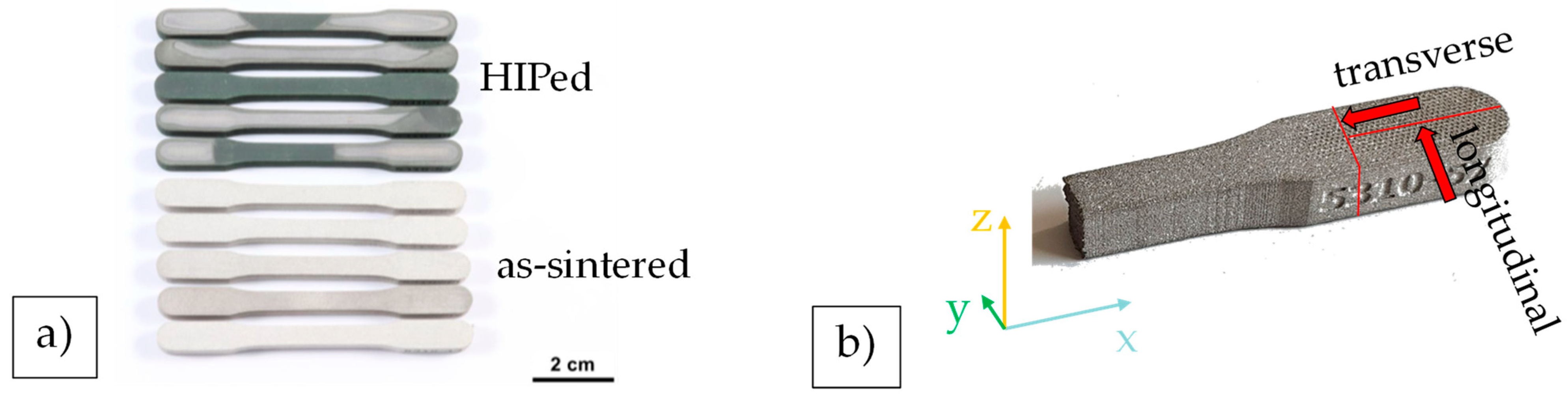
2.4. Tensile Testing

Tensile tests were carried out both at IWM on a universal tensile machine (Zwick Roell, Ulm, Germany) with a load cell of 100 kN, and at GKN Sinter Metals on an identical testing machine (Zwick Roell 100 kN). The test conditions were also identical and thus all results could be evaluated together afterward. A total of 18 specimens were tested, of which 10 specimens were post-treated by HIP and 8 specimens were in the as-sintered condition. The surface of the specimens was not machined after sintering. Figure 2a shows the dark discolored specimens that were subjected to HIP post-treatment in contrast to the light-colored specimens in as-sintered condition. The geometry of the tensile test specimens in Figure 2 was selected in accordance with the DIN EN ISO 2740 standard [35] for sintered metal materials, excluding hardmetals—tensile test pieces (ISO 2740: 2023).
To obtain information about the type of failure, the fracture surfaces of the specimens were analyzed macroscopically and microscopically after the tensile tests. The microscopic analysis was performed via scanning electron microscope (SEM) (Helios Nanolab G3 CX, FEI Company). Individual areas on the fracture surface, such as inclusions, were also studied by energy dispersive X-ray spectroscopy (EDX) (Oxford Instruments ‘Inca 7353, Oxford, UK).

2.5. Microstructure Analysis

The microstructure was examined metallographically at the mounting heads of the fractured tensile specimens. Since the microstructure of AM specimens is usually strongly dependent on the building direction, the microstructural analyses were carried out in different section planes, as defined in Figure 2b. In the further text, the y–z plane is referred to as the transverse section, and the x–z plane as the longitudinal section.
All specimens were prepared using standard metallographic procedures including cutting, grinding, polishing, and for some specimens, chemical etching (7s, Beraha 2). Sections were examined using light optical microscopy (LOM) (Zeiss Axio Imager M2m and Leica DM4000, Jena, Germany), SEM, and EDX (same equipment as in Section 2.4).
To determine the porosity, specimens in the as-sintered condition and after the subsequent HIP process were subjected to image-based pore analysis. In addition to the absolute value of porosity, the pore size distribution and the circularity of the pores were measured. For the image-based analyses, LOM images of unetched cross-sections at 200× magnification were examined using Image J 1.53 software [36]. For both conditions, two specimens in the longitudinal and transverse sections were examined. Ten different randomly selected areas were analyzed in each section.

2.6. Hardness

Hardness measurements were conducted at IWM on a Mitutoyo AVK-C2 hardness tester according to DIN EN ISO 6507 [37], with a load of HV10. For each condition, 3 specimens with 5 indentations each were examined to obtain significant statistics. The hardness indentations were measured by using LOM.

3. Results and Discussion

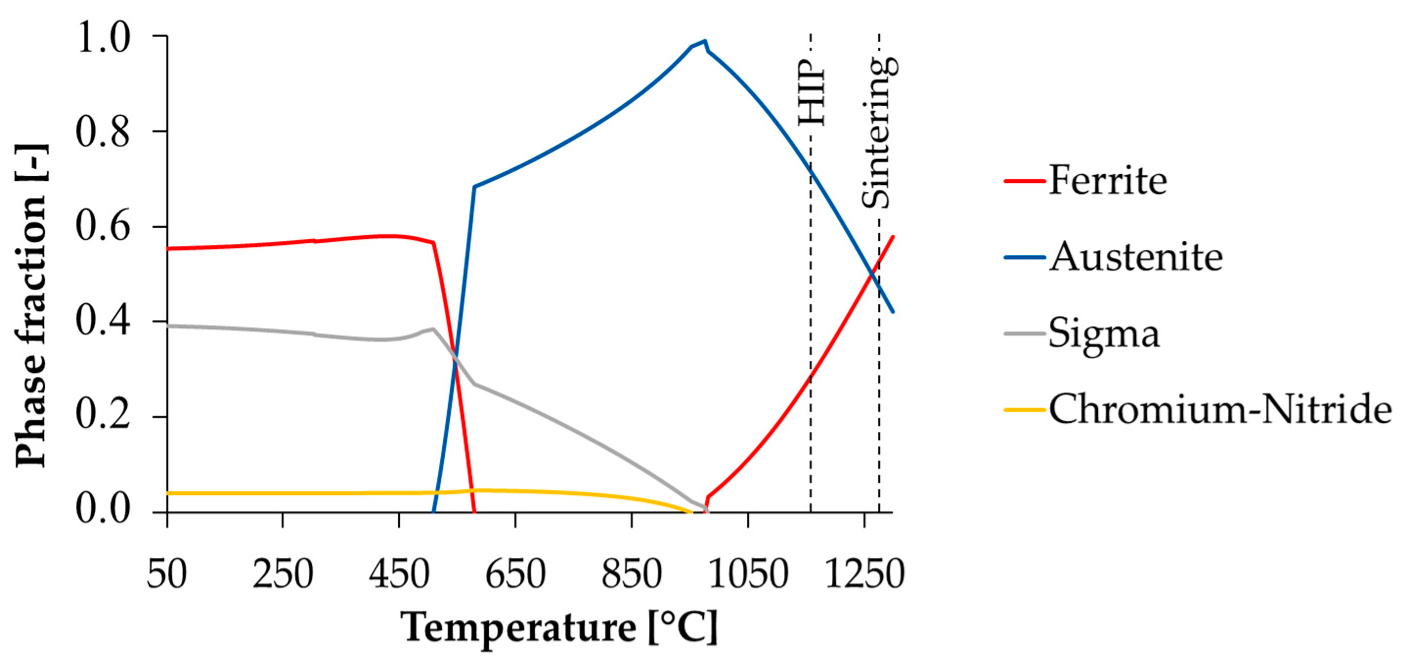
3.1. Equilibium Phases

The results of the thermodynamic modeling are presented in Figure 3 and indicate a duplex structure of 50% austenite and 50% delta ferrite at the sintering temperature of 1270 °C. This is in general very favorable for sintering and quite intentional, as diffusion in the bcc lattice is higher than in the fcc lattice and thus sintering activity can be increased to achieve a high density after sintering. Below the sintering temperature, the austenite content increases until an almost full austenitic microstructure is present at 975 °C. During further cooling, the embrittling sigma phase and small amounts of chromium nitride form in equilibrium. The formation of brittle sigma phase is a problem known in particular from duplex steels. However, the sigma phase generally forms only after long dwell times at high temperatures, so rapid cooling in the process can usually prevent its precipitation.

3.2. Microstructure

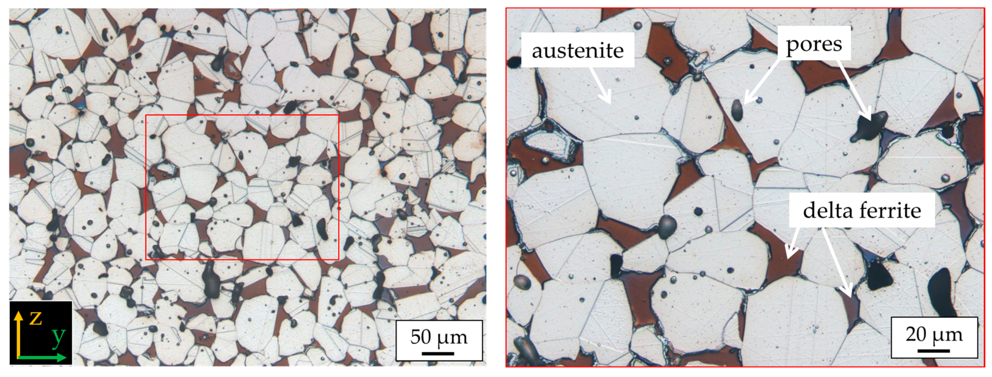
3.2.1. Microstructure in the As-Sintered Condition

Figure 4 shows a light microscopic overview image of a transverse section (a) and a longitudinal section (b) of a specimen after sintering.
In both cases, increased porosity can be seen, which appears to be randomly distributed. However, very close inspection in details 2 and 3 reveals isolated pore bands in the horizontal direction, as sometimes described for the MBJ process in literature [13,38]. On the bottom side, the porosity seems to be locally increased. Qualitatively, no significant difference between the porosity in the transverse section and the longitudinal section is visible. As a first impression, the visible residual porosity of the specimen is comparable in quantity to sintered components from other processes, such as MIM [39,40,41].
A more detailed examination with SEM in Figure 5 shows that other phases are found in addition to the porosity, that appear as edgy triple-point phases in the image.
The etched microstructure in Figure 6 identifies this phase as delta ferrite, as it was predicted by thermodynamic modeling. The amount of delta ferrite was determined by image analysis to be 10 vol.-% in the center of the specimen. The dark grey seam around the delta ferrite could possibly be sigma phase. However, this was not finally proven. Additionally, the appearance of chromium nitrides in the material could not be approved.
The EDX mapping in Figure 7 reveals the distribution of alloying elements in a randomly picked area of an as-sintered specimen. It can be seen that Al-rich oxides are present at the inner surfaces of pores. Additionally, certain areas are enriched in molybdenum. These are possibly delta ferrite regions. However, seams with even more Mo are visible around the Mo-rich areas. These seams were already visible in the etched microstructure in Figure 6 and might indicate the presence of a sigma phase. Sigma phase in duplex steels usually consists of Fe-Cr-Mo [42].

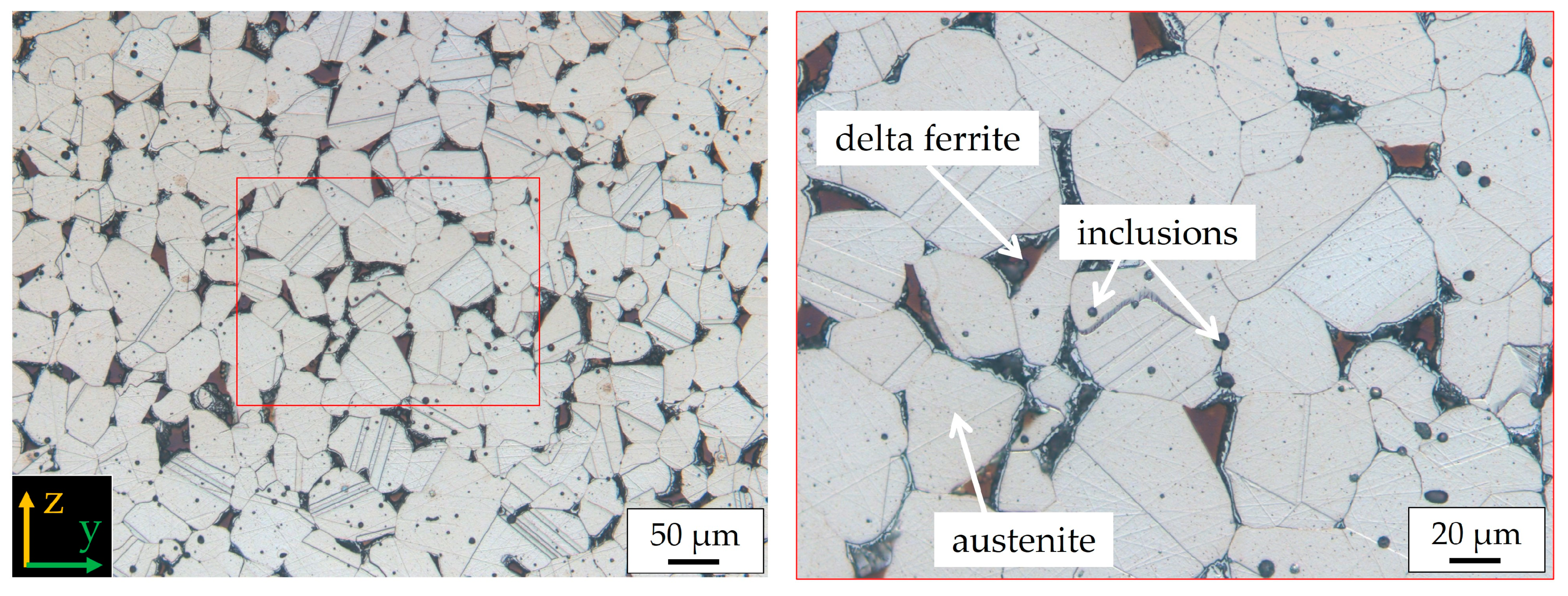
3.2.2. Microstructure after HIP Post-Treatment
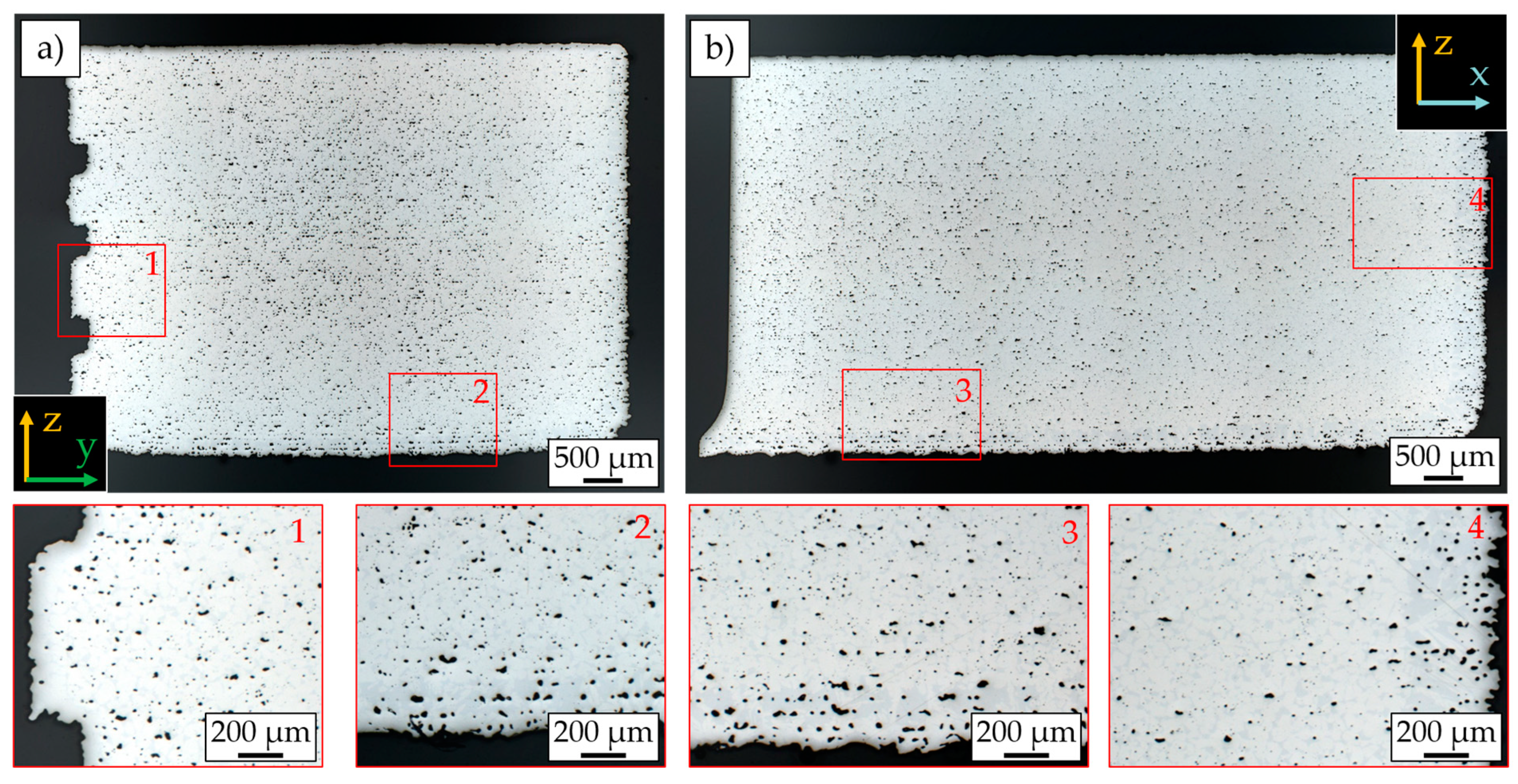
No pores are visible after HIP post-densification. The dark spots seen on the sections in Figure 8 could be partially identified as delta-ferrite when analyzed at higher resolution on the images of the etched microstructure in Figure 9.
The fraction of delta ferrite was determined by image analysis to be 2% and is thus significantly lower than in the specimens directly after sintering. The reason for this might be that the applied HIP temperature of 1150 °C is lower than the sintering temperature and that, according to Figure 3, a lower proportion of delta ferrite is present at this temperature. To completely avoid delta ferrite, the HIP cycle, or alternatively, a pressure-less heat treatment, would have to take place at even lower temperatures of about 980 °C and be followed by rapid cooling.
In addition to the angular delta ferrite phase, a very round phase, marked by arrows as inclusions in Figure 9, is visible.
The EDX mappings in Figure 10 reveal that these round inclusions are silicon- and manganese-rich oxides with contents of aluminum. Both silicon and manganese are present in the alloy system of the material. Aluminum is not part of the material composition and seems to be an impurity. However, Al is not only detected in combination with the Mn-Si-oxides, but also near the Mo-rich areas. In the as-sintered condition, Al and oxygen were only detected at pores. After HIP, both are found primary in combination with inclusions.

3.3. Pore Analysis

Image analytical pore analysis using LOM made it very difficult to distinguish pores from the oxide inclusions previously mentioned. Therefore, both were combined in the analysis in Table 2. It can be seen that the percentage of pores and inclusions together is 2.87 vol.-% before HIP and 0.77 vol.-% after HIP. However, higher-resolution SEM images (Figure 10) show that these detected 0.77 vol.-% are almost exclusively oxide inclusions and residual pores are very rare. Therefore, the authors assume that the 0.77 vol.-% measured in the HIP specimens are almost exclusively non-metallic inclusions. Theoretically, this proportion could be subtracted from the results before HIP, resulting in a pore fraction of 2.1 vol.-% before HIP. However, it was not sufficiently investigated whether the amount or size of the oxide inclusions increased after HIP. This point is the subject of further research. Therefore, it can only be stated with certainty that the porosity before HIP is at least 2.1 vol.-% and at most 2.87 vol.-%. This is a relatively low porosity for MBJ. Porosities in the range of 2.6–8 vol.-% are reported in the literature for MBJ specimens of 316L after optimization of powder characteristics or the sintering process [43,44,45,46]. The porosity comparison with the literature confirms that the concept of sintering with a high proportion of bcc phase is effective here and that this material is well adapted for sintering.
The pore size before HIP is on average 4.38 µm, although larger pores occur: 10% of all pores in the as-sintered condition are larger than 15.52 µm. After HIP, where it can be assumed that almost exclusively oxide inclusions are present, the mean size is 3.2 µm.

3.4. Hardness

The results of the hardness measurements are shown in Table 3. The first row shows the measured values for each specimen (specimen 1, specimen 2, and specimen 3). In the second row, all values were summed to give an average hardness for each condition. The standard deviation is given as the scatter of the values.
A comparison of the hardness values of the individual specimens within the same condition shows a considerable scattering of the measured values. The lowest hardness value in the as-sintered condition is 214 HV10 and the highest is 361 HV10. A similar scatter can be seen for the HIP condition. Hardness values after HIP densification range from 259 to 425 HV10. The scattering in both conditions is explained by pores and inclusions. Overall, an increase in hardness of approximately 40 HV10 is achieved by HIP treatment. The reason for this can be seen in the reduction of porosity.

3.5. Tensile Testing

The tensile test results are shown in Table 4. The as-sintered specimens show an ultimate tensile strength (UTS) of 741 MPa with a large scatter. The yield strength (YS) is 479 MPa and the elongation at break (A) is 23%. The latter two values show a small scatter. After HIP densification, the yield strength and tensile strength can be increased by almost 10%, while the elongation at break after HIP shows an even larger increase and raises from 23 to 35%. After HIP densification, strength values show a low scatter.
The graphical evaluation of the results as a boxplot representation in Figure 11 draws a more accurate picture. In this illustration, the end of the boxes and the center line describe the upper, middle, and lower quartiles. The small square inside the boxes shows the statistical mean value. If values are considered as outliers, they are shown as black diamonds outside the boxes and the whiskers. It can be seen that the scatter of the tensile strength before HIP is not that large, but that the apparently large scatter is mainly due to one outlier. Nevertheless, the entire picture does not change, and the HIP post-densification can clearly contribute to an improvement of all values measured in the tensile tests.
The high strength but also the reduced ductility of the nickel-free stainless steel compared to the typical austenite 316L produced via binder jetting (according to [43] YS of 175 MPa, UTS of 528 MPa, Elongation of 57%) can be attributed to the interstitial dissolved nitrogen. Using Rieder’s tensile tests on compositionally varied high-nitrogen steels as a reference, the achieved results of the HIP-densified specimens agree well with those from very dense specimens produced by centrifugal casting [47].

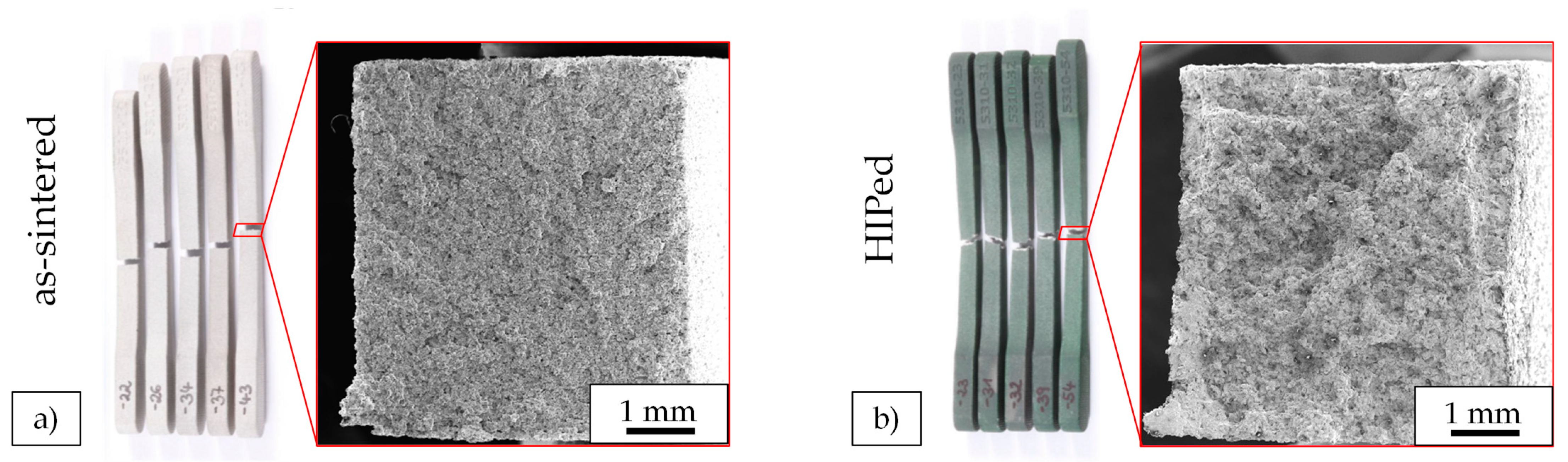
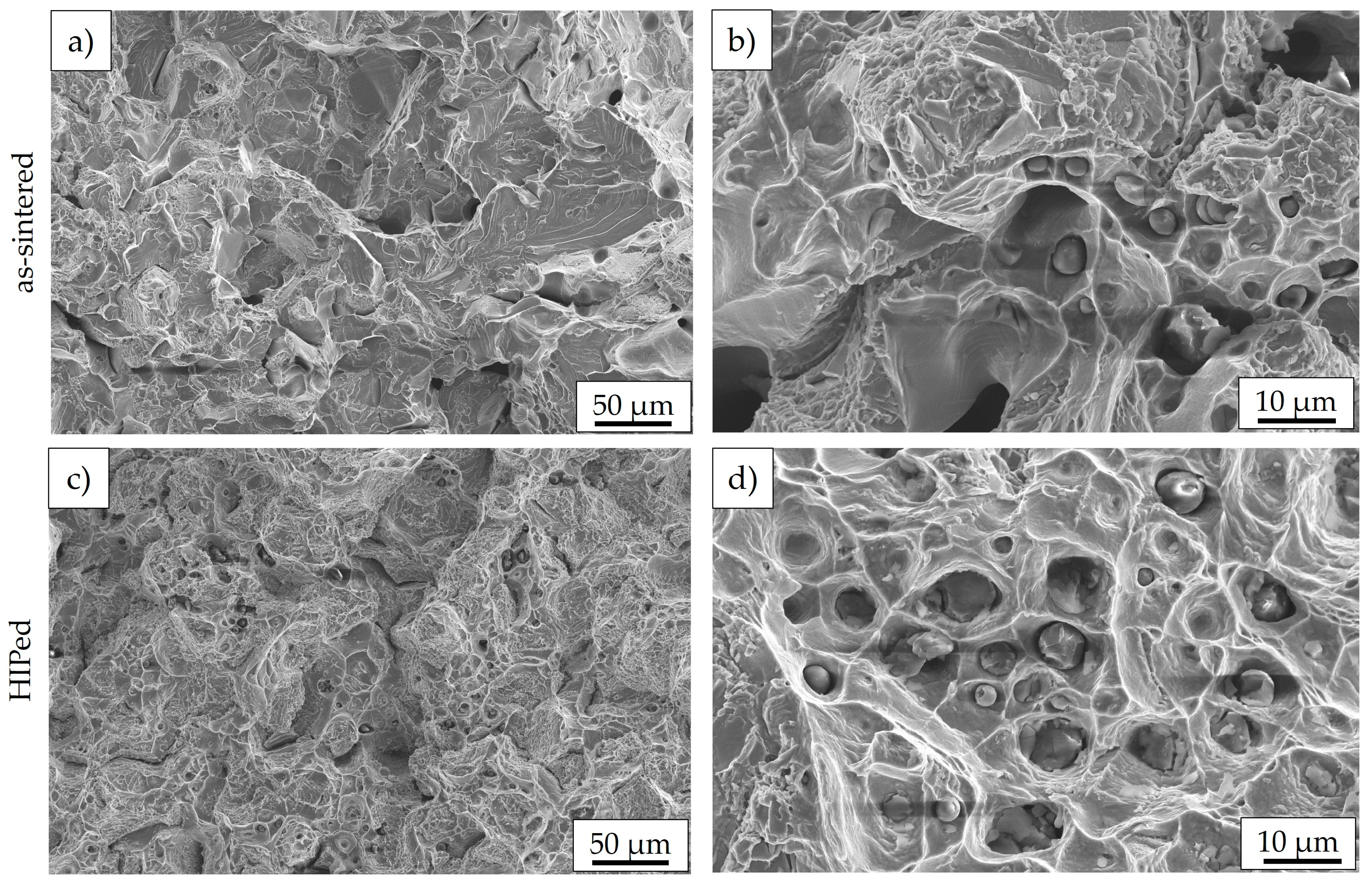
3.6. Fracture Analysis

The analysis of the fracture surfaces after tensile testing already reveals a macroscopic difference, as can be seen in Figure 12. The bright, as-sintered specimens in Figure 12a show very little plastic deformation at the fracture location. In contrast, the fracture surfaces of the dark HIP-compacted specimens in Figure 12a appear more ductile, as reflected by the rough surface and the 50% increase in fracture strain in the test results.
The high-resolution analysis of the fracture surfaces in SEM shows for the fracture surface in the as-sintered condition (Figure 13a) parts of cleavage fracture, whereas after HIP (Figure 13c), an almost completely ductile honeycomb fracture is present. In both conditions, the oxide inclusions already detected in the cross-sections are found on the fracture surfaces (Figure 13b,d).
Again, EDX analysis confirms that these are the previously identified Si-Mn-Al oxides. The EDX analysis shown in Figure 14 was performed on the fracture surface of a HIP post-densified specimen.
While almost no oxide inclusions are seen in the cross-sections of the as-sintered specimens, they can be found on the fracture surface of these specimens. Although it seems that the inclusions before and after HIP treatment do not differ in size and shape, it appears that there are more inclusions on the fracture surfaces of the HIP specimens. However, this was not quantified and may also be due to the different fracture types; as in the more ductile fracture of the HIP specimens, inclusions are generally very well visible within the honeycombs.

4. Conclusions

In the present study, a novel nickel-free austenitic high-nitrogen stainless steel was processed via metal binder jetting. Microstructure and tensile strength were analyzed in the as-sintered condition and after post-densification by HIP. The main results can be summarized as follows:
  • The porosity after sintering was 2.8 vol.-% at maximum, which means a relative density of at least 97.2% could be achieved by sintering. Subsequent densification by HIP was able to reliably densify almost all pores and leads to a relative density in the order of 100%. This represents a crucial accomplishment to enable application within the medical or watch and jewelry market. Most of the visual areas of components are polished to mirror class finish, which is enabled by full pore densification using HIP.
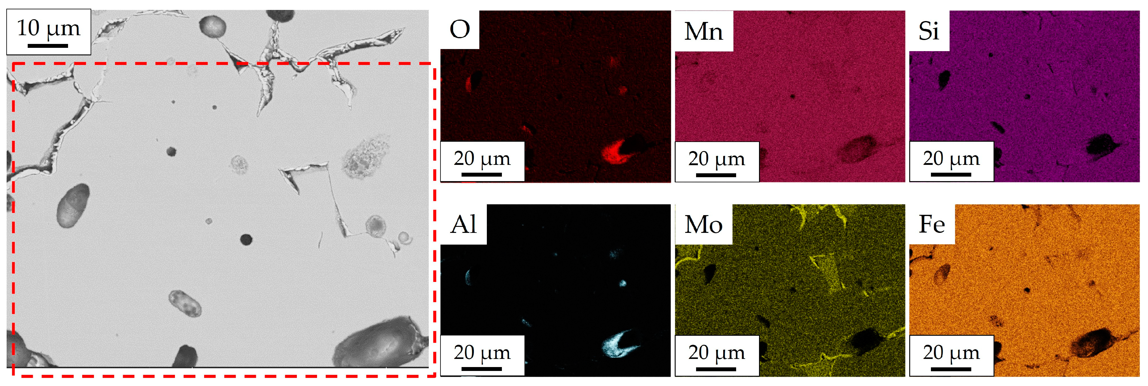
  • About 0.7 vol.% non-metallic inclusions were detected in the condition after HIP. In the as-sintered condition, it was not possible to distinguish pores and inclusions. The inclusions were determined as Si-Mn-Al-rich oxides, where only aluminum appears to be an impurity. These inclusions of approximately 3 µm size are found in both the cross-sections and the fracture surfaces.
  • In the as-sintered condition, about 10 vol.-% delta ferrite were detected, after HIP only vol.-2%. This is in good qualitative agreement with the delta ferrite content in thermodynamic simulations due to the lower HIP temperature compared to the sintering temperature.
  • Thermodynamic equilibrium calculations suggest susceptibility for sigma phase and chromium nitrides formation. None of these phases could be clearly identified. However, seams around the delta ferrite might indicate sigma phase due to increased molybdenum content.
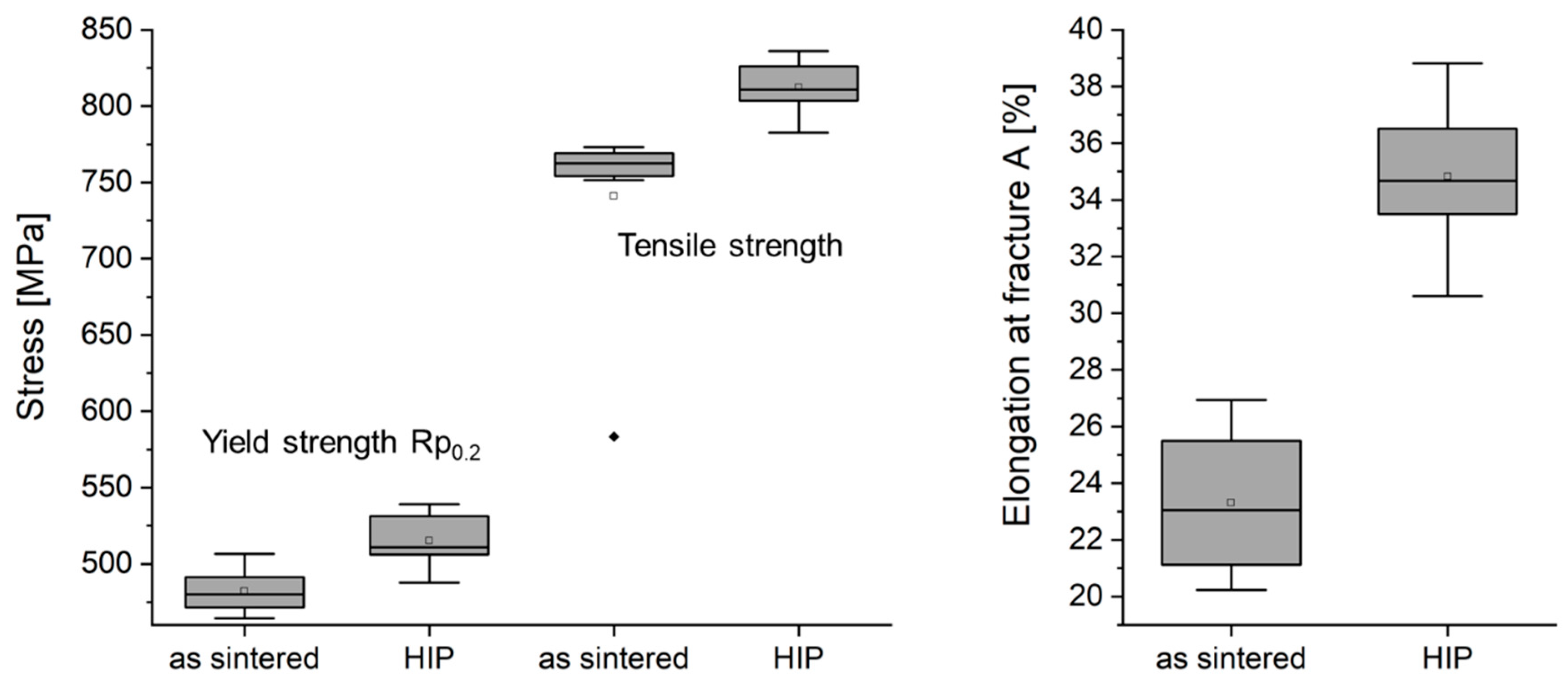
  • HIP post-densification improved both yield strength and tensile strength by about 10%. The increase in elongation at break due to HIP post-densification is in the order of 50%. The hardness also increases due to the densification of residual porosity.
It can also be assumed that the cyclic strength benefits even more from post-densification, which is to be investigated by fatigue tests in the future. This would also allow an assessment of the detrimental nature of the inclusions. If delta ferrite and sigma phase are not intentional, it is necessary to perform a heat treatment for this material to set the desired microstructure and avoid sigma phase and nitrides. Based on the thermodynamic calculations, heat treatment at 980 °C followed by quenching is recommended to obtain a fully austenitic microstructure. This temperature is about 150 °C below the HIP temperature. It would be feasible to lower the HIP temperature to 980 °C while simultaneously increasing the HIP pressure to 150–200 MPa. The authors assume that such HIP parameters can also be used to achieve adequate densification while maintaining a 100% austenite microstructure. If rapid cooling in the HIP system is technically possible, this will enable proper integration of the optimal heat treatment into a HIP cycle. Consequently, the setting of an optimum microstructure by a (pressure-assisted) heat treatment following the sintering process is an interesting and important research question to be investigated next.

Author Contributions

A.K.: conceptualization, methodology, visualization, validation, writing—original draft, supervision; F.R.: investigation, visualization, formal analysis, writing—original draft; S.H. (Simone Herzog): methodology, visualization, writing—review and editing; P.K.: conceptualization, investigation, resources, writing—original draft; S.H. (Simon Höges): conceptualization, supervision, resources, writing—review and editing; C.B.: resources. All authors have read and agreed to the published version of the manuscript.

Funding

This research received no external funding.

Institutional Review Board Statement

Not applicable.

Informed Consent Statement

Not applicable.

Data Availability Statement

Data are contained within the article.

Acknowledgments

The authors would like to express their sincere gratitude to OWL GmbH, Aachen for performing the HIP cycles.

Conflicts of Interest

The disclosure will be requested from the authors.

References

  1. Mostafaei, A.; Elliott, A.M.; Barnes, J.E.; Li, F.; Tan, W.; Cramer, C.L.; Nandwana, P.; Chmielus, M. Binder jet 3D printing—Process parameters, materials, properties, modeling, and challenges. Prog. Mater. Sci. 2021, 119, 100707. [Google Scholar] [CrossRef]
  2. Bai, Y.; Wagner, G.; Williams, C.B. Effect of Particle Size Distribution on Powder Packing and Sintering in Binder Jetting Additive Manufacturing of Metals. J. Manuf. Sci. Eng. 2017, 139, 081019. [Google Scholar] [CrossRef]
  3. Mirzababaei, S.; Pasebani, S. A Review on Binder Jet Additive Manufacturing of 316L Stainless Steel. J. Manuf. Mater. Process. 2019, 3, 82. [Google Scholar] [CrossRef]
  4. Rios, A.C.; Hryha, E.; Olevsky, E.; Harlin, P. Sintering anisotropy of binder jetted 316L stainless steel: Part I—Sintering anisotropy. Powder Met. 2022, 65, 273–282. [Google Scholar] [CrossRef]
  5. Ziaee, M.; Crane, N.B. Binder jetting: A review of process, materials, and methods. Addit. Manuf. 2019, 28, 781–801. [Google Scholar] [CrossRef]
  6. Oh, J.-W.; Nahm, S.; Kim, B.; Choi, H. Anisotropy in Green Body Bending Strength due to Additive Direction in the Binder-Jetting Additive Manufacturing Process. Korean J. Met. Mater. 2019, 57, 227–235. [Google Scholar] [CrossRef]
  7. Tang, Y.; Zhou, Y.; Hoff, T.; Garon, M.; Zhao, Y.F. Elastic modulus of 316 stainless steel lattice structure fabricated via binder jetting process. Mater. Sci. Technol. 2016, 32, 648–656. [Google Scholar] [CrossRef]
  8. Zhou, Y.; Tang, Y.; Hoff, T.; Garon, M.; Zhao, F.Y. The Verification of the Mechanical Properties of Binder Jetting Manufactured Parts by Instrumented Indentation Testing. Procedia Manuf. 2015, 1, 327–342. [Google Scholar] [CrossRef]
  9. Rojas-Nastrucci, E.A.; Nussbaum, J.; Weller, T.M.; Crane, N.B. Meshed rectangular waveguide for high power, low loss and reduced weight applications. In Proceedings of the 2016 IEEE MTT-S International Microwave Symposium (IMS), San Francisco, CA, USA, 22–27 May 2016; pp. 1–4. [Google Scholar]
  10. Chen, H.; Zhao, Y.F. Process parameters optimization for improving surface quality and manufacturing accuracy of binder jetting additive manufacturing process. Rapid Prototyp. J. 2016, 22, 527–538. [Google Scholar] [CrossRef]
  11. Fayazfar, H.; Salarian, M.; Rogalsky, A.; Sarker, D.; Russo, P.; Paserin, V.; Toyserkani, E. A critical review of powder-based additive manufacturing of ferrous alloys: Process parameters, microstructure and mechanical properties. Mater. Des. 2018, 144, 98–128. [Google Scholar] [CrossRef]
  12. Mao, Y.; Yuan, J.; Heng, Y.; Feng, K.; Cai, D.; Wei, Q. Effect of hot isostatic pressing treatment on porosity reduction and mechanical properties enhancement of 316L stainless steel fabricated by binder jetting. Virtual Phys. Prototyp. 2023, 18, e2174703. [Google Scholar] [CrossRef]
  13. Herzog, S.; Kaletsch, A.; Riehm, S.; Andreeva, E.; Hartwig, T.; Broeckmann, C. Jetting as Complementary Technology to Metal Injection Molding: Influence of HIP on microstructure and mechanical properties. In Proceedings of the EuroPM 2021, Online, 18–22 October 2021. [Google Scholar]
  14. Atkinson, H.V.; Davies, S. Fundamental aspects of hot isostatic pressing: An overview. Metall. Mater. Trans. A 2000, 31, 2981–3000. [Google Scholar] [CrossRef]
  15. Kunz, J.; Boontanom, A.; Herzog, S.; Suwanpinij, P.; Kaletsch, A.; Broeckmann, C. Influence of hot isostatic pressing post-treatment on the microstructure and mechanical behavior of standard and super duplex stainless steel produced by laser powder bed fusion. Mater. Sci. Eng. A 2020, 794, 139806. [Google Scholar] [CrossRef]
  16. Kasperovich, G.; Hausmann, J. Improvement of fatigue resistance and ductility of TiAl6V4 processed by selective laser melting. J. Am. Acad. Dermatol. 2015, 220, 202–214. [Google Scholar] [CrossRef]
  17. Masuo, H.; Tanaka, Y.; Morokoshi, S.; Yagura, H.; Uchida, T.; Yamamoto, Y.; Murakami, Y. Effects of Defects, Surface Roughness and HIP on Fatigue Strength of Ti-6Al-4V manufactured by Additive Manufacturing. Procedia Struct. Integr. 2017, 7, 19–26. [Google Scholar] [CrossRef]
  18. Qin, S.; Herzog, S.; Kaletsch, A.; Broeckmann, C. Improving the Fatigue Strength of Laser Powder Bed-Fused AISI M3:2 by Hot Isostatic Pressing. Steel Res. Int. 2022, 94, 2200435. [Google Scholar] [CrossRef]
  19. Kunz, J.; Saewe, J.; Herzog, S.; Kaletsch, A.; Schleifenbaum, J.H.; Broeckmann, C. Mechanical Properties of High-Speed Steel AISI M50 Produced by Laser Powder Bed Fusion. Steel Res. Int. 2020, 91, 1900562. [Google Scholar] [CrossRef]
  20. Spusta, T.; Svoboda, J.; Maca, K. Study of pore closure during pressure-less sintering of advanced oxide ceramics. Acta Mater. 2016, 115, 347–353. [Google Scholar] [CrossRef]
  21. Zhu, Y.; Wu, Z.; Hartley, W.D.; Sietins, J.M.; Williams, C.B.; Yu, H.Z. Unraveling pore evolution in post-processing of binder jetting materials: X-ray computed tomography, computer vision, and machine learning. Addit. Manuf. 2020, 34, 101183. [Google Scholar] [CrossRef]
  22. Li, M.; Du, W.; Elwany, A.; Pei, Z.; Ma, C. Metal Binder Jetting Additive Manufacturing: A Literature Review. J. Manuf. Sci. Eng. 2020, 142, 090801. [Google Scholar] [CrossRef]
  23. Lecis, N.; Mariani, M.; Beltrami, R.; Emanuelli, L.; Casati, R.; Vedani, M.; Molinari, A. Effects of process parameters, debinding and sintering on the microstructure of 316L stainless steel produced by binder jetting. Mater. Sci. Eng. A 2021, 828, 142108. [Google Scholar] [CrossRef]
  24. Mao, Y.; Li, J.; Li, W.; Cai, D.; Wei, Q. Binder jetting additive manufacturing of 316L stainless-steel green parts with high strength and low binder content: Binder preparation and process optimization. J. Am. Acad. Dermatol. 2021, 291, 117020. [Google Scholar] [CrossRef]
  25. Gibson, I.; Rosen, D.W.; Stucker, B.; Khorasani, M.; Rosen, D.; Stucker, B.; Khorasani, M. Binder Jetting. In Additive Manufacturing Technologies; Springer: Cham, Switzerland, 2021; pp. 237–252. [Google Scholar]
  26. Klee, L.; Bergs, T.; Solf, M.; Brimmers, J. Binder Jetting von Verzahnungen. Forsch. Ingenieurwesen 2023, 87, 779–791. [Google Scholar] [CrossRef]
  27. Huber, D.; Vogel, L.; Fischer, A. The effects of sintering temperature and hold time on densification, mechanical properties and microstructural characteristics of binder jet 3D printed 17-4 PH stainless steel. Addit. Manuf. 2021, 46, 102114. [Google Scholar] [CrossRef]
  28. Sufiiarov, V.; Polozov, I.; Kantykov, A.; Khaidorov, A. Binder jetting additive manufacturing of 420 stainless steel: Densification during sintering and effect of heat treatment on microstructure and hardness. Mater. Today Proc. 2020, 30, 592–595. [Google Scholar] [CrossRef]
  29. Nandwana, P.; Kannan, R.; Siddel, D. Microstructure evolution during binder jet additive manufacturing of H13 tool steel. Addit. Manuf. 2020, 36, 101534. [Google Scholar] [CrossRef]
  30. Hecker, L.; Schaak, C.; Hoeges, S.; Koehnen, P. Investigation of Printing, Sintering, and HIP-processing of Nickel-Free Stainless-Steel for Binder Jetting. In Proceedings of the WorldPM 2022, Lyon, France, 9–13 October 2022. [Google Scholar]
  31. Patnaik, L.; Maity, S.R.; Kumar, S. Status of nickel free stainless steel in biomedical field: A review of last 10 years and what else can be done. Mater. Today Proc. 2020, 26, 638–643. [Google Scholar] [CrossRef]
  32. Sonderegger, M. Optimised Sintering and Heat Treatment of the Nickel-Free High-Nitrogen MIM-Steel X15CrMnMoN17-11-3; Listemann AG: Winterthur, Switzerland, 2006. [Google Scholar]
  33. Zou, L.; Liu, R.; Su, Z.; Gao, J.; Li, L. Sintering optimization of high nitrogen nickel free austenitic stainless steel prepared by Metal Injection Molding. J. Phys. Conf. Ser. 2023, 2459, 12121. [Google Scholar] [CrossRef]
  34. Andersson, J.-O.; Helander, T.; Höglund, L.; Shi, P.; Sundman, B. Thermo-Calc & DICTRA, computational tools for materials science. Calphad 2002, 26, 273–312. [Google Scholar] [CrossRef]
  35. DIN EN ISO 2740:2009-10; Sintered Metal Materials, Excluding Hardmetals-Tensile Test Pieces (ISO 2740:2009); German Version EN ISO 2740:2009. ISO: Geneva, Switzerland, 2009. [CrossRef]
  36. Rueden, C.T.; Schindelin, J.; Hiner, M.C.; Dezonia, B.E.; Walter, A.E.; Arena, E.T.; Eliceiri, K.W. ImageJ2: ImageJ for the next generation of scientific image data. BMC Bioinform. 2017, 18, 529. [Google Scholar] [CrossRef]
  37. DIN EN ISO 6507-1:2018-07; Metallic Materials-Vickers Hardness Test-Part 1: Test Method (ISO 6507-1:2018); German Version EN ISO 6507-1:2018. ISO: Geneva, Switzerland, 2018. [CrossRef]
  38. Mostafaei, A.; De Vecchis, P.R.; Nettleship, I.; Chmielus, M. Effect of powder size distribution on densification and microstructural evolution of binder-jet 3D-printed alloy 625. Mater. Des. 2019, 162, 375–383. [Google Scholar] [CrossRef]
  39. Zhang, Y.; Feng, E.; Mo, W.; Lv, Y.; Ma, R.; Ye, S.; Wang, X.; Yu, P. On the Microstructures and Fatigue Behaviors of 316L Stainless Steel Metal Injection Molded with Gas- and Water-Atomized Powders. Metals 2018, 8, 893. [Google Scholar] [CrossRef]
  40. Ji, C.; Loh, N.; Khor, K.; Tor, S. Sintering study of 316L stainless steel metal injection molding parts using Taguchi method: Final density. Mater. Sci. Eng. A 2001, 311, 74–82. [Google Scholar] [CrossRef]
  41. Veltl, G.; Hartwig, T.; Petzoldt, F.; Kunze, H.-D. Investigations on Metal Injection Molding of 316L Stainless Steel. Mater. Manuf. Process. 1995, 10, 425–438. [Google Scholar] [CrossRef]
  42. Wang, R. Precipitation of sigma phase in duplex stainless steel and recent development on its detection by electrochemical potentiokinetic reactivation:A review. Corros. Commun. 2021, 2, 41–54. [Google Scholar] [CrossRef]
  43. Frykholm, R.; Takeda, Y.; Andersson, B.-G.; Carlström, R. Solid State Sintered 3-D Printing Component by Using Inkjet (Binder) Method. J. Jpn. Soc. Powder Powder Met. 2016, 63, 421–426. [Google Scholar] [CrossRef]
  44. Mao, Y.; Cai, C.; Zhang, J.; Heng, Y.; Feng, K.; Cai, D.; Wei, Q. Effect of sintering temperature on binder jetting additively manufactured stainless steel 316L: Densification, microstructure evolution and mechanical properties. J. Mater. Res. Technol. 2023, 22, 2720–2735. [Google Scholar] [CrossRef]
  45. Verlee, B.; Dormal, T.; Lecomte-Beckers, J. Density and porosity control of sintered 316L stainless steel parts produced by additive manufacturing. Powder Met. 2012, 55, 260–267. [Google Scholar] [CrossRef]
  46. Juan, H.L. Effect of Temperature ratio (Ts/Tm) and Time on the Sintering Behavior of Metallic 316L Stainless Steel Coupons Coupons Produced Using Jet-binder Technology. Ph.D. Thesis, University of Pittsburgh, Pittsburgh, PA, USA, 2017. [Google Scholar]
  47. Riedner, S. Höchstfeste Nichtrostende Austenitische CrMn-Stähle mit (C+N). Ph.D. Thesis, Ruhr-Universität Bochum, Bochum, Germany, 2011. [Google Scholar]
Figure 1. Particle size distribution (a) and SEM image of the used nickel-free stainless-steel powder (b).
Applsci 13 12676 g001
Figure 2. (a) Illustration of the tensile specimen geometry used and (b) visualization of the different grinding planes on the head of a tensile specimen.
Applsci 13 12676 g002
Figure 3. Equilibrium calculation of different phase fractions as a function of temperature.
Applsci 13 12676 g003
Figure 4. Light optical microscopic overview of the porosity in an as-sintered specimen in (a) transverse section and in (b) longitudinal section with details 1–4.
Applsci 13 12676 g004
Figure 5. Backscattered electron image of the microstructure of an as-sintered specimen in transverse section in different magnification.
Applsci 13 12676 g005
Figure 6. Light microscopic image and detail of the microstructure of an as-sintered specimen in transverse section after chemical etching.
Applsci 13 12676 g006
Figure 7. Back scattered electron image and EDX mappings of a specimen in the as-sintered condition.
Applsci 13 12676 g007
Figure 8. Light microscopic overview of a specimen after HIP in (a) the transverse section and in (b) the longitudinal section.
Applsci 13 12676 g008
Figure 9. Light microscopic image of the microstructure of a specimen after HIP in the transverse section after chemical etching in a different magnification.
Applsci 13 12676 g009
Figure 10. Backscattered electron image and EDX mappings of a specimen after HIP.
Applsci 13 12676 g010
Figure 11. Graphical illustration showing the results of tensile tests on specimens from the different conditions in a box-plot representation.
Applsci 13 12676 g011
Figure 12. Macroscopic fracture appearance of tensile specimens in (a) the as-sintered and (b) the after HIP condition, illustrated by photo and exemplary secondary electron image.
Applsci 13 12676 g012
Figure 13. Secondary electron images of the fracture surfaces of tensile specimens tested in the (a,b) as-sintered and (c,d) after HIP condition. Non-metallic inclusions are visible in (b,d).
Applsci 13 12676 g013
Figure 14. EDX spectrum taken punctually on a non-metallic inclusion on the fracture surface of a tensile specimen in the HIP condition.
Applsci 13 12676 g014
Table 1. Measured chemical composition of the used powder in wt.-%.
FeCrNiMoMnNCSiOS
Bal.16.90.13.3811.520.3490.050.580.0750.005wt.-%
Table 2. Overview of the percentage of pores or inclusions in the different conditions (as-sintered and after HIP) as well as the measured circularity and size distribution.
Porosity/Inclusions [vol.-%]Circularity [%]d10 [µm]d50 [µm]d90 [µm]
as-sintered2.87 ± 0.7687.1 ± 1.90.98 ± 0.104.38 ± 0.2915.25 ± 1.09
After HIP0.77 ± 0.0895.4 ± 0.50.70 ± 0.063.20 ± 0.066.98 ± 0.10
Table 3. Overview of the measured Vickers hardness HV10 [-] in the different conditions.
Hardness As-Sintered [-]Hardness after HIP [-]
S1/S2/S3275 ± 42224 ± 7269 ± 18314 ± 53280 ± 15279 ± 18
Average256 ± 36291 ± 39
Table 4. Summary table of the properties measured in the tensile test for the different conditions.
YS [MPa]UTS [MPa]A [%]
as-sintered479 ± 14741 ± 6023 ± 2
After HIP515 ± 15812 ± 1535 ± 3
Disclaimer/Publisher’s Note: The statements, opinions and data contained in all publications are solely those of the individual author(s) and contributor(s) and not of MDPI and/or the editor(s). MDPI and/or the editor(s) disclaim responsibility for any injury to people or property resulting from any ideas, methods, instructions or products referred to in the content.

