Article

Nonlinear Dynamic Mechanical Characteristics of Air Springs Based on a Fluid–Solid Coupling Simulation Method

1
College of Vehicle and Traffic Engineering, Henan University of Science and Technology, Luoyang 471023, China
2
State Key Laboratory of Rail Transit Vehicle System, Southwest Jiaotong University, Chengdu 610031, China
*
Author to whom correspondence should be addressed.
Appl. Sci. 2023, 13(23), 12677; https://doi.org/10.3390/app132312677
Submission received: 27 October 2023 / Revised: 21 November 2023 / Accepted: 24 November 2023 / Published: 26 November 2023

Abstract

:
The use of air springs has become widespread in various industries due to their exceptional superelastic properties; however, their strong nonlinear characteristics have become a hindrance to numerical simulations of air springs and have garnered increasing attention. This paper examined the nonlinear dynamic mechanical characteristics of air springs from a fluid–structure interaction perspective and verified the accuracy of the simulation analysis model through quasistatic tension and compression experiments. The average relative errors for air spring load and gas pressure were found to be 8.1% and 7.7%, respectively, which supports the validity of the model. The impact of frequency and amplitude excitations on the axial load characteristics of air springs was investigated through tension and torsion testing. The results showed that increasing the excitation frequency improves the stability of the axial load, while increasing the excitation amplitude enhances the axial load value. The change in axial compression was found to be more significant than that in axial tension, as it was affected not only by the axial load but also by the radial load, which is a key factor affecting the dynamic characteristics of air springs. A radial load analysis model was established to study the influence of frequency and amplitude excitations on the axial load characteristics of air springs. The simulation results indicated that under different amplitudes, the radial load of air springs goes through four stages: a steady period, rising period, steady period, and falling period. Additionally, under the same amplitude, the radial load value increases with an increase in frequency. This research on the dynamic load characteristics of air springs under amplitude and frequency excitations is important for their application in low-frequency and low-amplitude vibration environments, and its findings can be utilized to improve the technical parameters of air springs for suspension damping.

1. Introduction

Air springs have gained widespread use in automobiles, aerospace engineering, and rail transit due to their exceptional variable stiffness characteristics. Despite their widespread use, research into air springs is still faced with numerous technical challenges, particularly in regard to their strong nonlinearities in material, geometry, and contact. The numerical simulation of large deformations in air springs under fluid–structure interactions is particularly challenging and requires further study. This paper presents a numerical simulation model for air springs that considers fluid–structure interactions, aimed at investigating the vibration characteristics of air springs under different excitation loads in both axial and radial directions. Karpenkoa studied the characteristics of nonlinear materials by employing piezoelectric micro-vibration tests and frequency analyses [1]. The goal was to better understand the mechanical behavior of air springs under low-frequency and low-amplitude excitations in various directions.
Currently, the research on air springs primarily centers around shock absorption, nonlinear behavior, and ejection impact. For example, Skrickij investigated cavitation effects which negatively influence the performance of a monotube shock absorber in a road vehicle [2]. With the advancement of technology and increasing demands for enhanced riding comfort in vehicles, air suspension systems have seen widespread implementation in rail vehicles and automobiles. This article presents the nonlinear mechanical characteristics of air springs, focusing on the influence of frequency and amplitude excitation on axial and radial loads. The research of this paper becomes more and more important. Researchers have conducted extensive studies on the stiffness characteristics, model refinement, dynamic behavior, and overall performance of air suspension systems.
In terms of stiffness characterization, Wu [3], Quaglia [4,5], and Chen [6] have conducted comprehensive studies on the identification of nonlinear parameters in the dynamic stiffness of air springs, the derivation of stiffness expressions, and the creation of a uniform stiffness model. The effectiveness of these models has been verified through various experimental methods. Tang [7] analyzed the impact of the piston cone angle and height on the static stiffness of single-cavity cross-sectional and bending air springs. Zhang et al. [8] presented an air spring model with a variable orifice in an auxiliary chamber and optimized its parameters, resulting in improved performance in semiactive control. Sreenivasan and Keppanan [9] derived a formula for calculating the volume change rate of curved bellows under different suspension heights. In terms of dynamic characteristics, the vertical and lateral behavior of air springs under varying loads and speeds have been explored through experimental methods [10]. Chen [11] analyzed the failure modes of air spring suspensions with double horizontal valves and their impact on truck dynamics. Ryaboy [12] also studied the vertical dynamic behavior of air springs and further analyzed the stability of a vibration isolation system consisting of multiple air springs. Li [13] proposed a hybrid isolator comprised of a maglev actuator and air spring aimed at applications in active–passive vibration isolation systems for ship machinery.
As a commonly used damping component in rail vehicles, air springs have been widely adopted in secondary suspension systems that connect bogies and vehicle bodies. The research on the impact of air springs on vehicle dynamics performance has been relatively extensive. In a study by Wu et al. [14], the effect of three different air spring models on the straight-line running stability and curve passing safety of rail vehicles was investigated. In a study by Mazzola [15], a method was proposed to accurately define a component model of air spring secondary suspension in railway vehicles through indoor testing and model recognition technology. Qi et al. [16] conducted research on a rubber air spring used in high-speed EMUs and described its viscoelastic damping characteristics using fractional order theory. The parameters in the fractional order model were identified based on the measured data, and a fractional order correction model was established to optimize the aerodynamic model. Facchinetti et al. [17] compared and analyzed two modeling methods of secondary air spring suspension and evaluated the impact on the precision of multibody simulations of rail vehicle dynamics. In addition to the above studies, research on the construction of equivalent models for air springs is also a trending topic. This mainly involves testing and theoretical analyses to obtain the load equivalent curve and derive an analytical solution for the stiffness of air springs [18]. Li et al. [19] studied the impact of geometric parameters on the vertical stiffness of air springs based on a derived theoretical formula. Bhattacharya et al. [20] discussed the effect of linearizing air spring stiffness on the performance of dampers and provided the frequency changes of dampers with different design parameters.
The nonlinear characteristics of air springs have attracted significant attention in the research community. In the derivation of nonlinear theoretical formulas, Zargar et al. [21] developed a nonlinear model and validated its accuracy through experiments. Chen et al. [22] studied the modeling and dynamic characteristic of air springs with a throttling damping orifice and auxiliary chamber. Other studies have focused on the rubber mechanical characteristics of air springs with orifices and additional air chambers [23], and found that the stiffness of air springs is dependent on the frequency and excitation amplitude [24]. These studies on the dynamic stiffness of air springs have been conducted through numerical models, model simplification, and bench tests [25]. Zhu et al. [26,27] confirmed the accuracy of the predicted nonlinear dynamic characteristics of a proposed model through bench tests under large-amplitude excitation and varying precompression and pretension conditions. The current research on the cord parameters of air springs has focused mainly on modifying the tensile formula of the cord rubber material parameters and deriving theoretical numerical models and simplified models [28,29,30]. These nonlinear studies on air springs have contributed to the advancement of air spring technology and its applications in the field of suspension.
Furthermore, there have also been preliminary discussions on the ejection impact of air springs, yielding promising results. Liu, Li, and Zhu [31,32,33] proposed an air spring impact test system for rail vehicle propulsion that utilizes air spring inflatable energy storage ejection work, leading to improved ejection acceleration, lower noise, and faster reaction times compared to traditional methods. The Xiao’s team conducted a series of studies on the ejection performance of air springs, exploring the force characteristics under compressed gas using the CV method, as well as the impact of gas mass flow and air spring thickness on ejection performance [34]. The team also analyzed the load characteristics of air springs and investigated the influence of cord parameters on ejection performance and static load characteristics [35,36].
While much work has been conducted on the theory and application of air springs, there has been limited research on the low-frequency and small-amplitude vibration characteristics of air springs in both axial and radial directions. This study aimed to fill this gap by establishing a numerical analysis model of air springs under axial and radial loads based on fluid–structure coupling, thermodynamics, and dynamics theory. The dynamic load characteristics of air springs were studied through numerical simulations and experimental verification under axial and radial amplitude and frequency excitation.

2. Materials and Methods

The utilization of the fluid–structure coupling approach to model air spring inflation was primarily achieved through the implementation of a fluid cavity model, a fluid model, and an adiabatic process, making it a crucial aspect for simulating the interaction between the air spring structure and the gas during inflation.

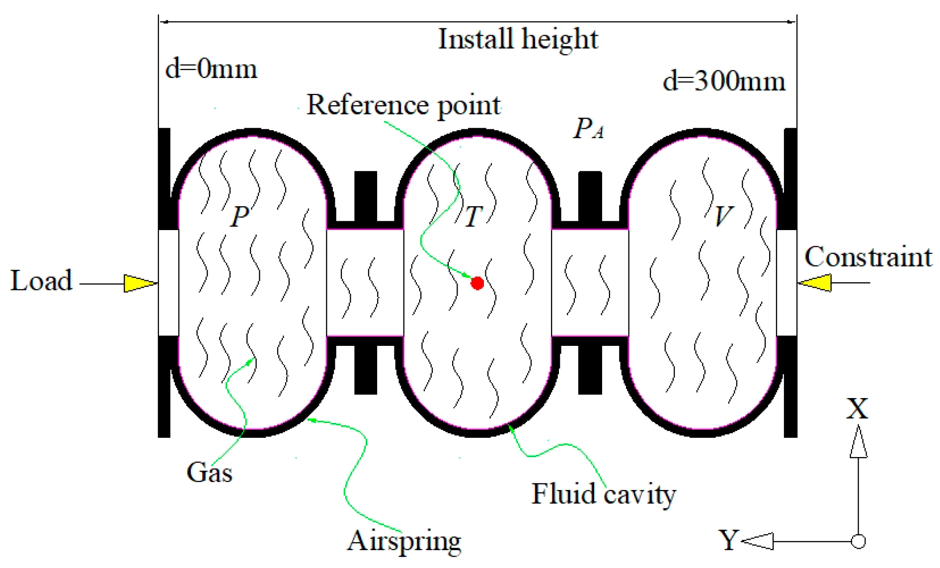
2.1. Fluid-Structure Coupling Construction Method

2.1.1. Fluid Cavity Model

The application of a face-based fluid cavity model, as opposed to the traditional element-based static fluid cavity, allows for the simulation of the interaction between the fluid (liquid or gas) within an air spring and the cavity structure. This approach not only enables the prediction of the mechanical response of a gas- or liquid-filled structure, but also provides a more accurate representation of the behavior of the system. Figure 1 illustrates a flow cavity structure diagram under an external load.
The fluid–structure interaction in air spring inflation is effectively modeled through the utilization of a face-based fluid cavity model, which simulates the relationship between the air spring structure and the gas within. The structural response to an external load is dependent not only on the load itself, but also on the fluid pressure, which forms a coupling relationship. The face-based fluid cavity provides a means through which this coupling can be analyzed. The fluid cavity boundary is defined by the surface of the element, with the normal direction facing the interior of the cavity. The surface element must ensure that the element node completely encloses the fluid cavity. A face-based fluid element is applied on the boundary of the fluid chamber, and each chamber is assigned a unique reference point and a single degree of freedom corresponding to the fluid chamber pressure. The fluid parameters, such as density, bulk modulus, and expansion coefficient, must be defined for each chamber. The three curved air spring used in this study has a symmetrical structure, with its reference point located at the junction of the symmetry plane, as depicted in Figure 1.

2.1.2. Fluid Model

In this study, fluid models were utilized to simulate the behavior of liquids or gases in an air spring system. The fluid models can be broadly classified into hydraulic and pneumatic fluid models. Hydraulic fluid models were used to simulate the behavior of almost incompressible fluids, while introducing compressibility by assuming a linear relationship between pressure and volume. The required parameters for this model include the bulk modulus and reference density. Furthermore, the relationship between density and temperature can be simulated through the thermal expansion of the fluid. The reference density of the fluid ρ R is obtained by considering the fluid density at zero pressure and the initial temperature θ I .
ρ R = ρ 0 , θ I
The compressibility of a fluid is described by a fluid volume model, which characterizes the relationship between the pressure and volume of the fluid, taking into account its thermodynamic properties and behavior under various conditions. The model considers the linear relationship between pressure and volume, and includes parameters such as bulk modulus and reference density, which are used to simulate the incompressible behavior of the fluid. Additionally, the thermal expansion of the fluid is also taken into account, and the relationship between density and temperature is established based on the fluid’s initial temperature and pressure conditions.
P = K V ( P , θ ) V 0 ( θ ) V 0 θ I ρ 0 , θ I = K ρ R ρ 1 ( P , θ ) ρ 0 1 ( θ )
where P represents the current pressure, θ represents the current temperature, K represents the fluid bulk modulus, V = ( P , θ ) represents the current volume, ρ ( P , θ ) represents the density at pressure P and temperature θ , V 0 ( θ ) represents the volume under 0 pressure and temperature θ , V 0 ( θ ) represents the Volume at 0 pressure and initial temperature θ , and ρ 0 ( θ ) represents the density at 0 pressure and temperature θ .
The coefficient of thermal expansion is a measure of the fractional change in fluid volume with respect to temperature. It is defined as the derivative of fluid volume with respect to temperature at a reference temperature, and is expressed as a function of temperature. This coefficient accounts for the change in fluid volume due to thermal expansion and is used to capture the temperature-dependent behavior of the fluid.
The fluid volume change due to thermal expansion can be described by the coefficient of thermal expansion, which is defined as a function of temperature. The reference temperature, θ 0 , is used to determine the average coefficient of thermal expansion, α(θ), which represents the total coefficient of expansion at the reference temperature.
V 0 θ = V 0 θ I 1 + 3 α θ θ θ 0 3 α θ I θ I θ 0
where θ 0 is the reference temperature of the coefficient of thermal expansion and α θ is the average coefficient of thermal expansion.
When the coefficient of thermal expansion is constant, it is expressed as a function of fluid density alone, without the need for a reference temperature θ 0 . In this case, the change in fluid volume due to thermal expansion can be described as a linear relationship between fluid density and temperature.
ρ 0 θ = ρ R / 1 + 3 α θ θ θ 0 3 α θ I θ 0
The compressible aerodynamic fluid model is based on an ideal gas, and the ideal gas equation is defined below.
P = ρ R ( θ θ Z )
where R is the gas constant, θ is the current temperature, θ Z is absolute zero, ρ is the gas density, and the absolute pressure or total pressure P is deduced as
P = P b + P A
where P A is the ambient pressure and P b is the gauge pressure. R is obtained from the general gas constant R ~ and the gas molecular weight M W .
R = R ~ M W

2.1.3. Adiabatic Process

The calculation of the air spring chamber temperature is based on the predefined temperature at the reference point, and the temperature of the fluid inside is determined through the conservation of energy during the adiabatic process. This assumption assumes that no heat is transferred into or out of the fluid cavity, except through the fluid exchange defined by the model or through the generator.
The mass flow rate in the gas spring chamber can be obtained from the conservation of mass, which can be obtained from the following formula.
m = m ˙ i n m ˙ o u t
where m is the mass of the fluid, m ˙ i n is the mass flow rate into the fluid cavity, and m ˙ o u t is the mass flow rate of the fluid cavity.
The first law of thermodynamics is applied to derive the energy equation of the air spring system. By considering only the internal energy of the fluid cavity, the equation describing the energy of the fluid is obtained while disregarding the kinetic and potential energy components.
d ( m E ) d ( t ) = m ˙ i n H i n m ˙ o u t H o u t w ˙ Q ˙
where w ˙ is the work done by the expansion of the fluid cavity and w ˙ = P V ˙ ; H i n and H o u t are the inflow and outflow times, respectively. Q ˙ is the thermal energy flow rate, generated by the heat transfer from the surface of the fluid cavity, and when it is positive, it means that the heat will flow out from the mainstream body cavity, and the unit energy E is given.
E = E I + θ I θ C V ( T ) d T
where E I is the initial unit energy at the initial temperature θ I , C V is the specific heat of equal volume, and ideal gases are only temperature-dependent. H is the specific enthalpy, which is defined as
H = H I θ I θ C P ( T ) d T
where H I is the specific enthalpy at the initial temperature θ I ; C P is the constant pressure specific heat capacity, which is only related to the temperature of the ideal gas, and the parameters such as the pressure, temperature, and density of the gas spring chamber are obtained through the ideal gas law, energy balance, and mass conservation equation.

2.2. Fluid Model Characterization

The effective simulation of air springs requires the establishment of numerical analysis models based on nonlinear theory through the fluid–structure interaction method and virtual work principle.

2.2.1. Virtual Work Principle

The simulation of inflatable cavities in aerodynamic conditions can be achieved by utilizing a fluid unit. Based on the principle of augmented virtual work, the ideal gas equation can be utilized to determine the boundary conditions of the closed gas. By combining these boundary conditions with the virtual work equation of the air spring structure, an effective numerical analysis model can be established to capture the nonlinear behavior of the fluid–structure interaction [37,38].
The volume of fluid in the air spring chamber is a function of fluid pressure, temperature, and mass. The fluid cavity volume V ¯ is obtained from the fluid pressure P and gas temperature θ , which is equal to the actual chamber volume V , and the virtual work expression of the gas spring structure expansion is realized by the following constraint equation [39].
V ¯ = f ( P , θ , m )
V ¯ = V
Furthermore, the contribution of the pressure within the gas spring chamber to the virtual work is taken into consideration.
δ Π * = δ Π P δ V δ P V V ¯
where δ Π * is the augmented virtual work expression and δ Π is the virtual work expression of the fluid-free cavity structure. A negative sign means that an increase in chamber volume releases fluid energy, where structural displacement and fluid pressure are the main variables. The rate of augmented virtual work obtained by differentiation is as follows.
d δ Π * = d δ Π P d δ V d P δ V d V d V ¯ δ P
δ Π * = δ Π P e δ V e δ P [ e V e e V ¯ e ]
where P d δ V is the pressure load stiffness, and since all elements of the air spring chamber have the same pressure, the extended virtual work can be expressed as the sum of the virtual work of multiple elements, as shown in the following equation.
Π * = e [ δ Π e P δ V e δ P V e V ¯ e ]

2.2.2. Fluid Action of the Chamber

The nonlinear behavior of air springs is influenced by various factors, including geometric nonlinearity, material nonlinearity, and contact nonlinearity [40]. Furthermore, the pressure variation within the chamber also affects the nonlinear behavior of air springs. The fluid element based on surface modeling shares a node with the gas spring structure, and by linking it to a reference point, it transforms into a bulk element.
The following are the node coordinates that define the fluid element situated within the chamber of the air spring [41].
X x , y = i N i ( ξ , η ) X i ( x , y )
where N i is a fluid element-shaped function, which is expressed by the isoparameter coordinates ξ , η , and X i ( x , y ) are the reference point coordinates.
The Jacobian determinant of this fluid is as follows.
X ξ = i N i ξ X i X η = i N i η X i
The following equation is obtained from the fluid element normal vector n and the microelement area d A .
n d A = X ξ X η d ξ d η
From the microelement area, the microelement volume can be deduced as follows:
d V = 1 3 ( X i X ) n d A
The fluid element volume can be further obtained by the following equation through differential integration.
V ¯ e = d V = 1 1 1 1 1 3 ( X i X ) ( X ξ X η ) d ξ d η
Since the temperature of all cells in the chamber is the same, the fluid volume of each cell can be calculated using the following formula:
V ¯ e = V ¯ ( P , θ , m e )
The volume of gas can be expressed as
V = e V ¯ e = e V ¯ P , θ , m e = m ρ ( P , θ )
From this equation, the fluid density ρ ( P , θ ) in the chamber can be obtained.
ρ P , θ = ρ R θ R θ A ( P + P A ) ( θ θ A ) ( P R + P A )
where P A is the temperature at the reference point density ρ R , P R is the pressure when the reference point density is ρ R , θ A is the ambient temperature, and P A is the ambient pressure.
The gas pressure volume [21] in the air spring chamber can be obtained from the combination of Formula (24) and Formula (25).
d V d P = m d ρ ρ 2 d P = m ρ R θ R θ A ( P + P A ) ( θ θ A ) ( P R + P A ) 2
Through the above fluid–structure coupling theory, the fluid cavity model, fluid model, and adiabatic process of air spring chamber gas were established, and the coupling relationship between the air spring binding structure and chamber gas was obtained. Combined with the principle of virtual work and the fluid action of the chamber, the changes in parameters such as the deformation, volume, pressure, and temperature of the air spring under the action of pressure gas were finally obtained. By setting parameters to the values shown in Table 1 and Table 2 below, a numerical simulation model suitable for the nonlinear simulation of air spring was established. The nonlinear static and dynamic load characteristics of air springs were simulated and analyzed.

3. Results of Air Spring Compression Experiment

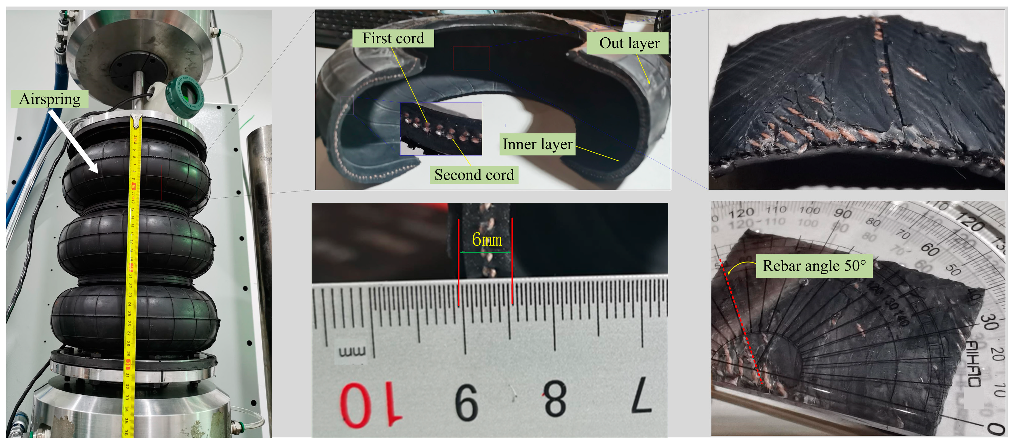
3.1. Model Parameters for Air Spring
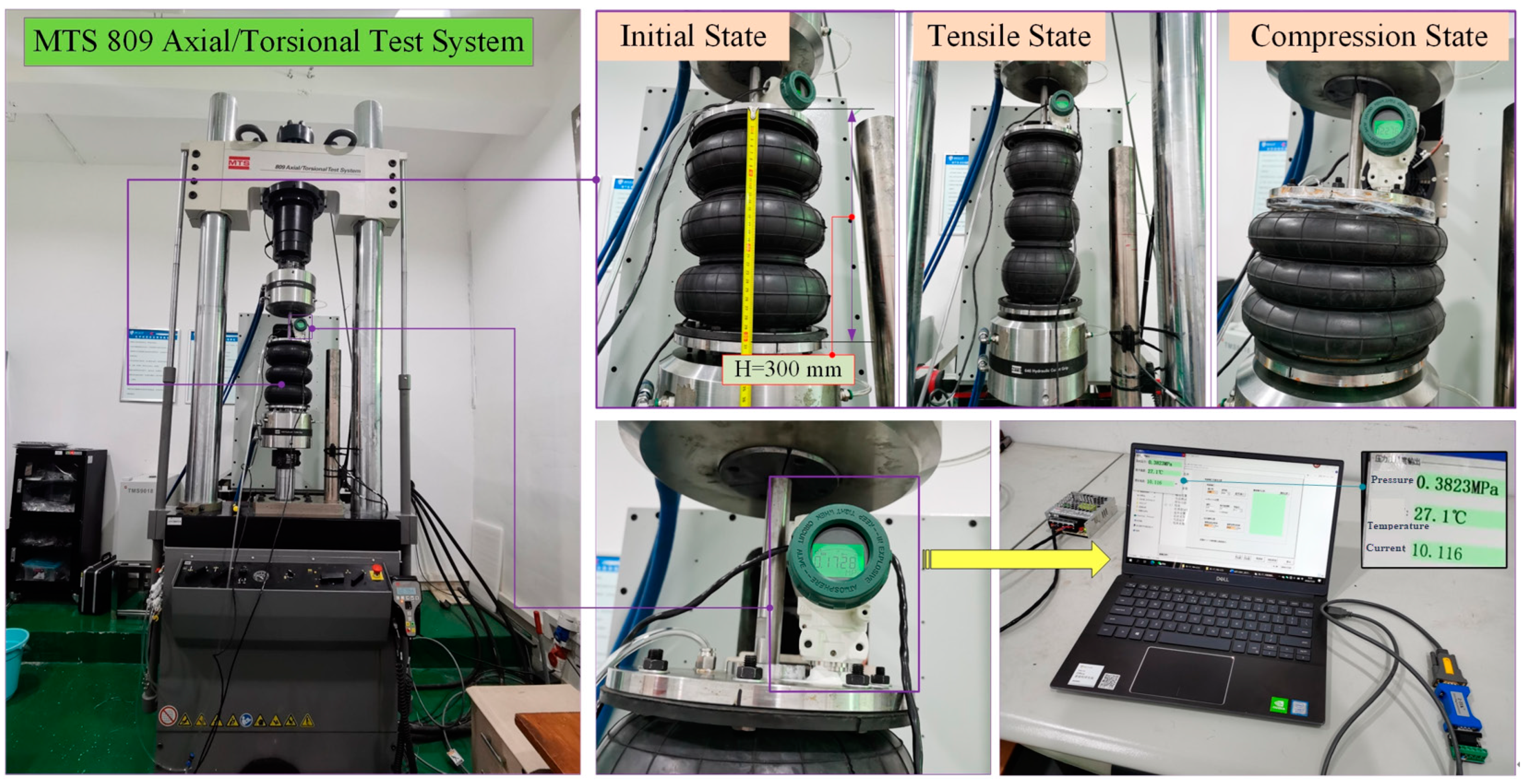
In the present study, a static tension and compression model of an air spring was developed and is depicted in Figure 1. The key parameters in the model include the absolute pressure (P) and atmospheric pressure (PA) within the chamber, the chamber temperature (T), and the volume (V) of the air spring chamber. The air spring comprises a rubber matrix and cords, and the Mooney–Rivlin model was employed to simulate the rubber matrix of the air spring. The cord parameters in the air spring, such as the number of cord layers, cord angle, cord spacing, cord diameter, and cord center distance, were also taken into consideration. As depicted in Figure 2, the air spring consisted of an inner and outer rubber, with cords sandwiched between the two layers. The air spring had an initial length of 300 mm and wall thickness of 6 mm. It was symmetrically arranged with two cord layers and a cord angle of 50°. The initial parameters used for the simulation of the air spring are presented in Table 1 and Table 2.

3.2. Testing Method

In this study, an MTS809 tension and torsion tester was utilized to conduct the tension and compression tests, as well as axial dynamic vibration tests on the air spring. The initial working height of the air spring was set at 300 mm, and air was supplied to the air spring chamber via an air compressor. A state-of-the-art intelligent pressure sensor was installed at the top of the air spring, enabling real-time monitoring of the pressure and temperature within the chamber. The experimental setup and principles are depicted in Figure 3 and Figure 4, respectively.

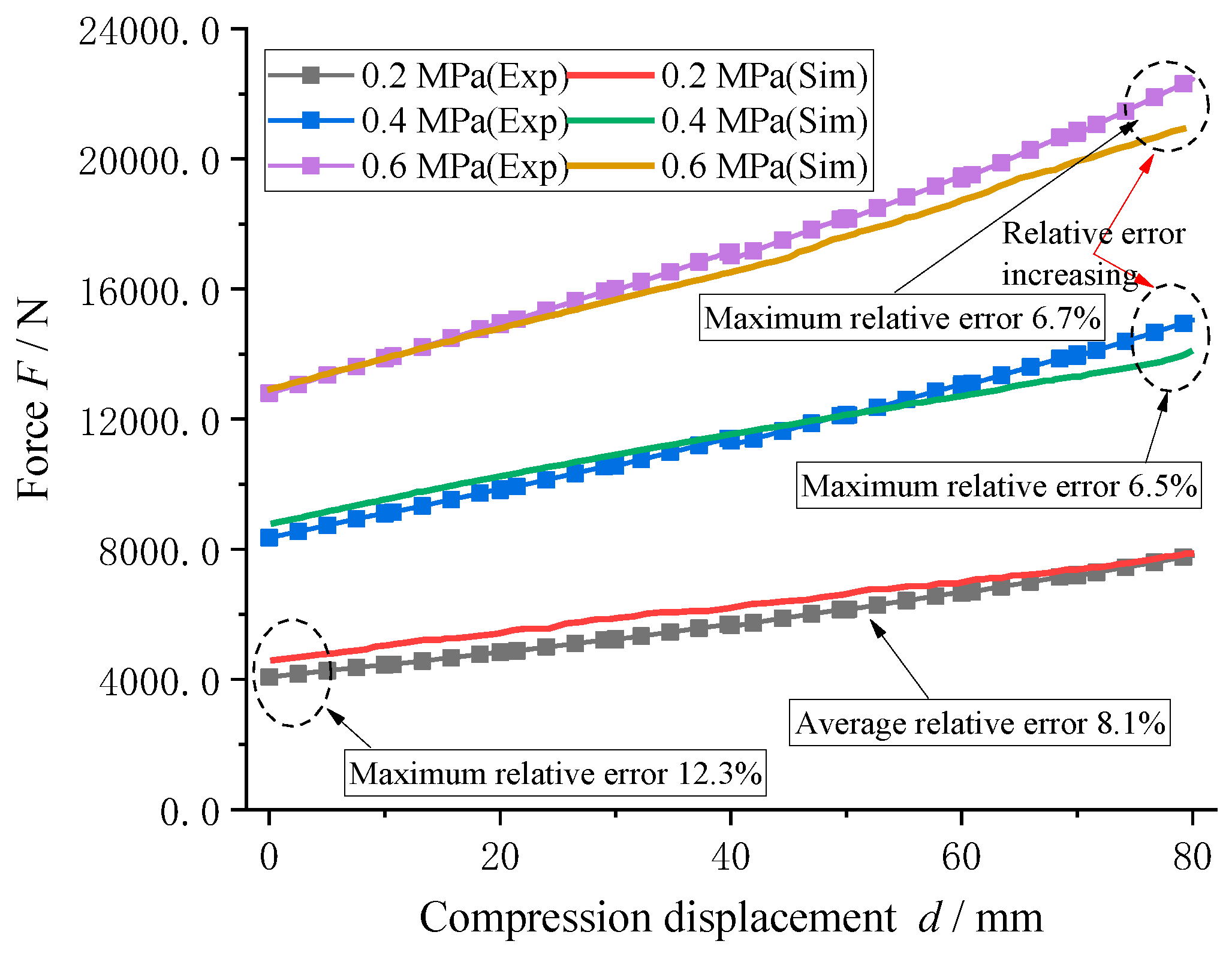
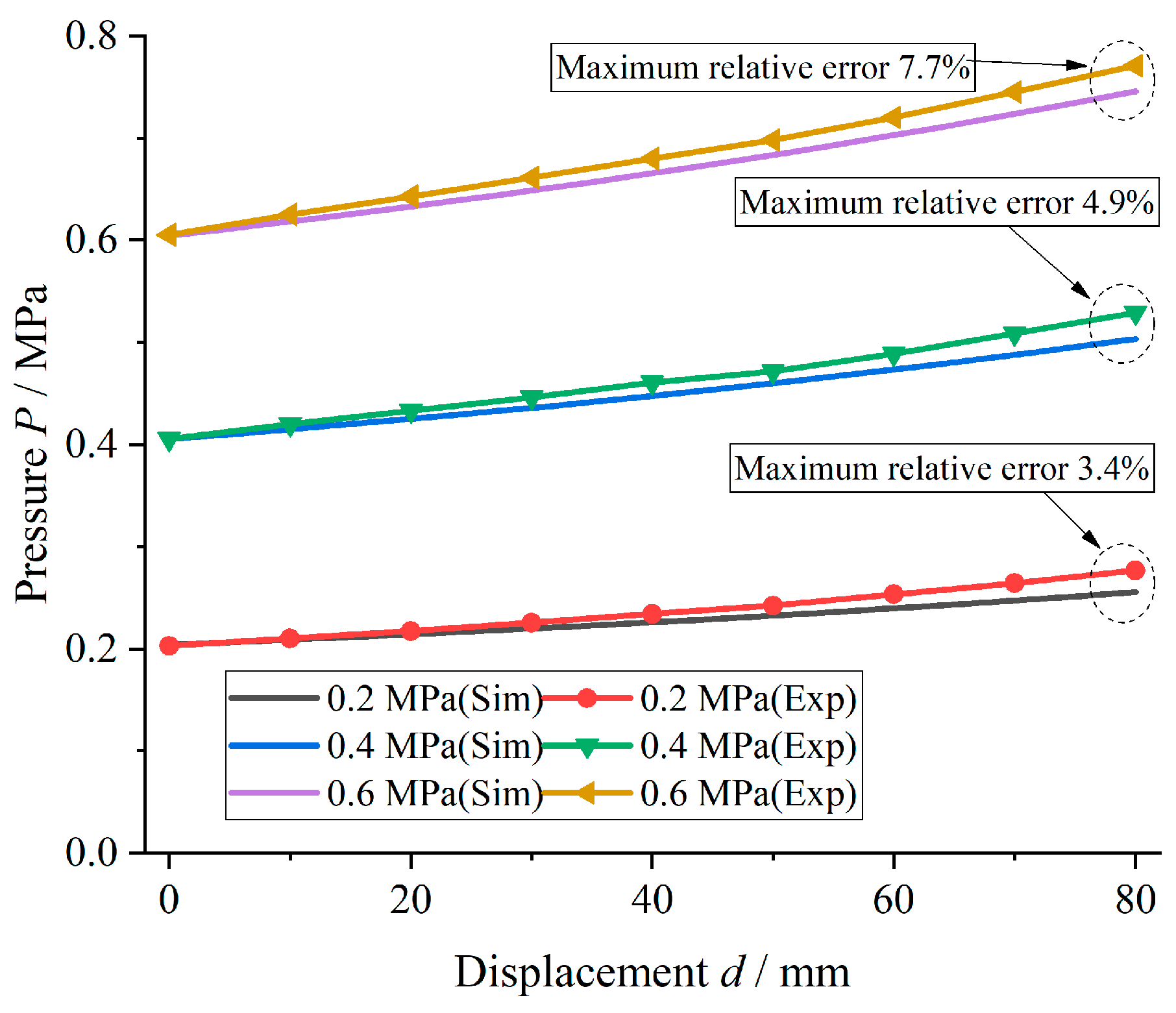
3.3. Experimental Verification

The results of the experimental compression test and numerical simulation of the air spring under various initial pressures are presented in Figure 5. The initial pressures considered in this study were 0.2 MPa, 0.4 MPa, and 0.6 MPa.
The results of the compression test and simulation analysis of the air spring under different initial pressures of 0.2, 0.4, and 0.6 MPa are presented in Figure 5. The comparison of the simulation results with the experimental data shows that the trend of change in the air spring load with compression displacement was accurately reflected, with maximum relative errors of 12.3%, 6.5%, and 6.7%, respectively. Despite the relative error being greater than 10% under a lower initial pressure of 0.2 MPa, the average relative error was found to be less than 10%, satisfying the required accuracy for load calculation. The normal working pressure of the air spring is 0.7 MPa, and the minimum compression height is 98 mm. In this study, a 80 mm compression displacement was applied to the air spring with initial pressures of 0.2, 0.4, and 0.6 MPa for verification purposes. The comparison of the simulation results and experimental data for the chamber pressure of the air spring is shown in Figure 6.
As evident from the comparison of the simulation and experimental results displayed in Figure 6, there is a correlation between the change in compression displacement and the relative error of the air spring chamber pressure. Despite the increase in relative error with the increase in compression displacement, the maximum relative error was only 7.7%, demonstrating good agreement between the simulation and experimental results. These results verify the accuracy of the established air spring model and pave the way for further investigations into the impact of radial loads on the dynamic mechanical characteristics of air springs.

4. Results and Discussion

4.1. Axial Dynamic Mechanical Characteristics of the Air Spring

A dynamic mechanical characterization test of the air spring under various axial frequency excitations was performed using an MTS testing machine. The air spring was subjected to an initial pressure of 0.3 MPa prior to the vibration test. Varying frequencies and amplitudes of excitation were applied to the air spring to investigate the effect of the externally applied frequency and amplitude excitations on the axial load behavior of the air spring under a given initial pressure.

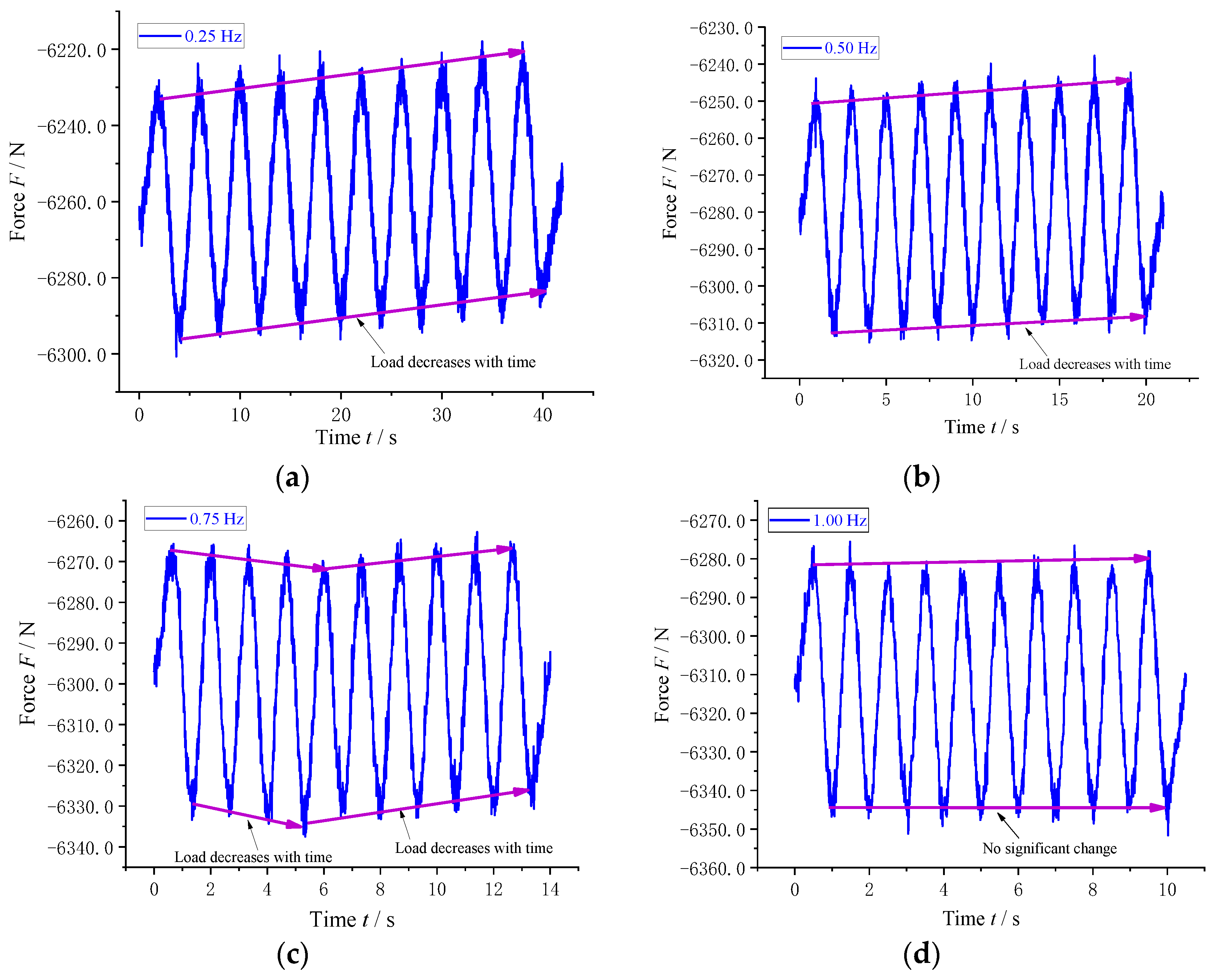
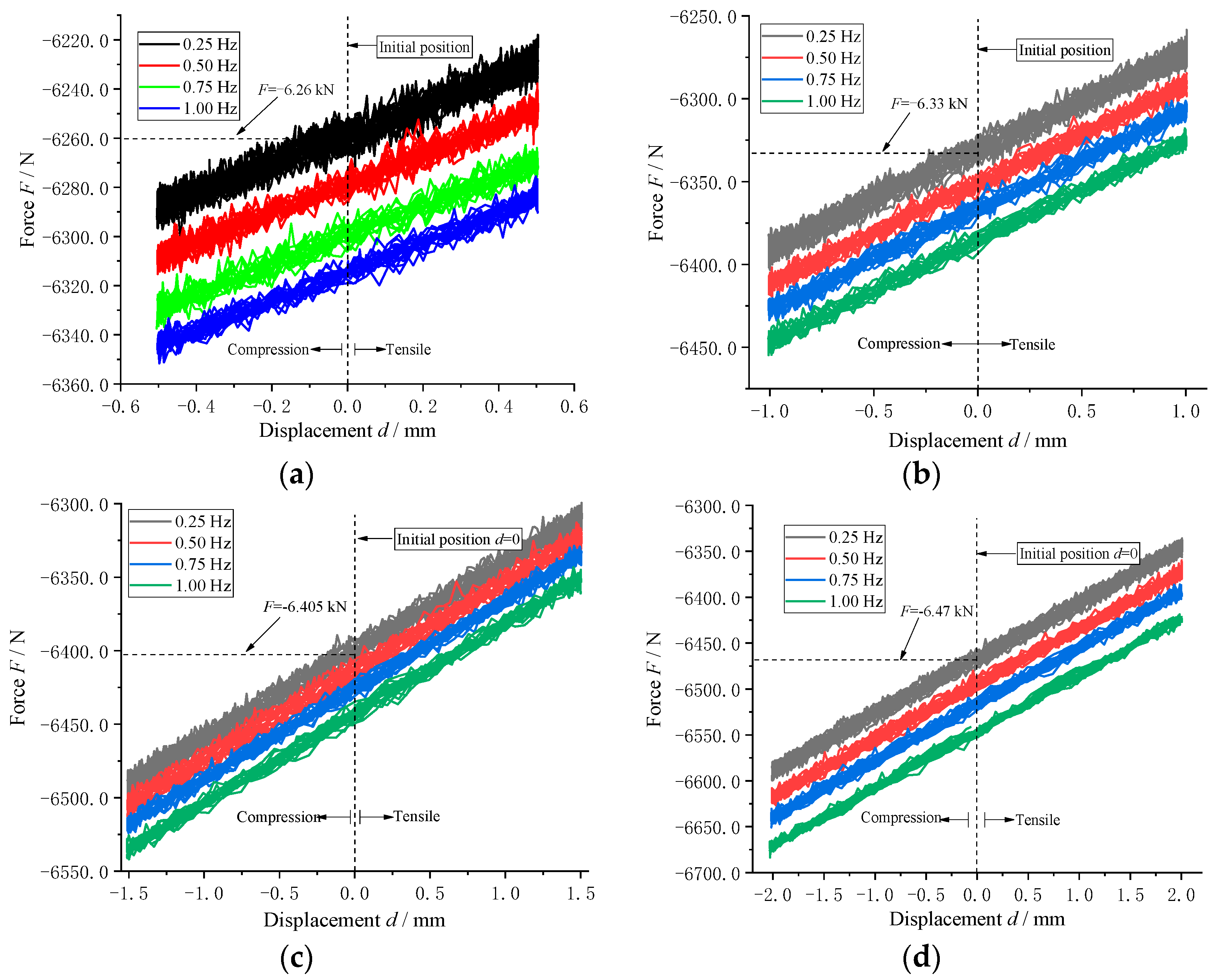
4.1.1. Influence of Frequency Excitation on Axial Load Characteristics of Air Spring

The axial load behavior of an air spring under a constant initial pressure of 0.3 MPa was evaluated in response to sine amplitude excitations of 0.5 mm, under varying frequency conditions. The results of the analysis, covering a minimum of 10 cycles selected across different frequency excitations, are presented in Figure 7.
The results of the axial load characteristics of the air spring under an initial pressure of 0.3 MPa and a 0.5 mm sine amplitude excitation are depicted in Figure 7. The figure demonstrates that changes in frequency can have a notable effect on the axial load of the air spring, particularly at frequencies below 1.0 Hz, with the most pronounced effect at 0.5 Hz and 0.25 Hz. With the progression of vibration time, a linear decrease in the maximum peak value of the axial load of the air spring was observed, implying that the axial load at low frequencies decreases over the vibration process. A load peak value increase followed by a decrease with increasing time was observed for the axial load of the air spring when the vibration frequency was 0.75 Hz. On the other hand, when the excitation frequency increased to 1.0 Hz, the axial load of the air spring remained consistent with no significant variations, signifying that lower frequency vibrations can have a significant impact on the axial load characteristics of air springs.

4.1.2. Effect of Amplitude Excitation on Axial Load Characteristics of Air Spring

As depicted in Figure 8, the results of the study on the effect of amplitude excitation on the axial load of the air spring under an initial pressure of 0.3 MPa revealed that the axial load behavior of the air spring changes with varying frequency and amplitude excitations.
As evident in Figure 8, under the same initial pressure of 0.3 MPa, and for different amplitude excitations, the axial load of the air spring increased with an increase in vibration frequency. At a frequency of 0.25 Hz, the initial load of the air spring shows differences with respect to different amplitudes, with the corresponding axial load for amplitudes ranging from 0.5 to 2.0 mm being −6.26 to −6.47 kN, respectively. This trend of increase in axial initial load with increasing frequency held true for other vibration frequencies as well, although the increase in amplitude was relatively small.

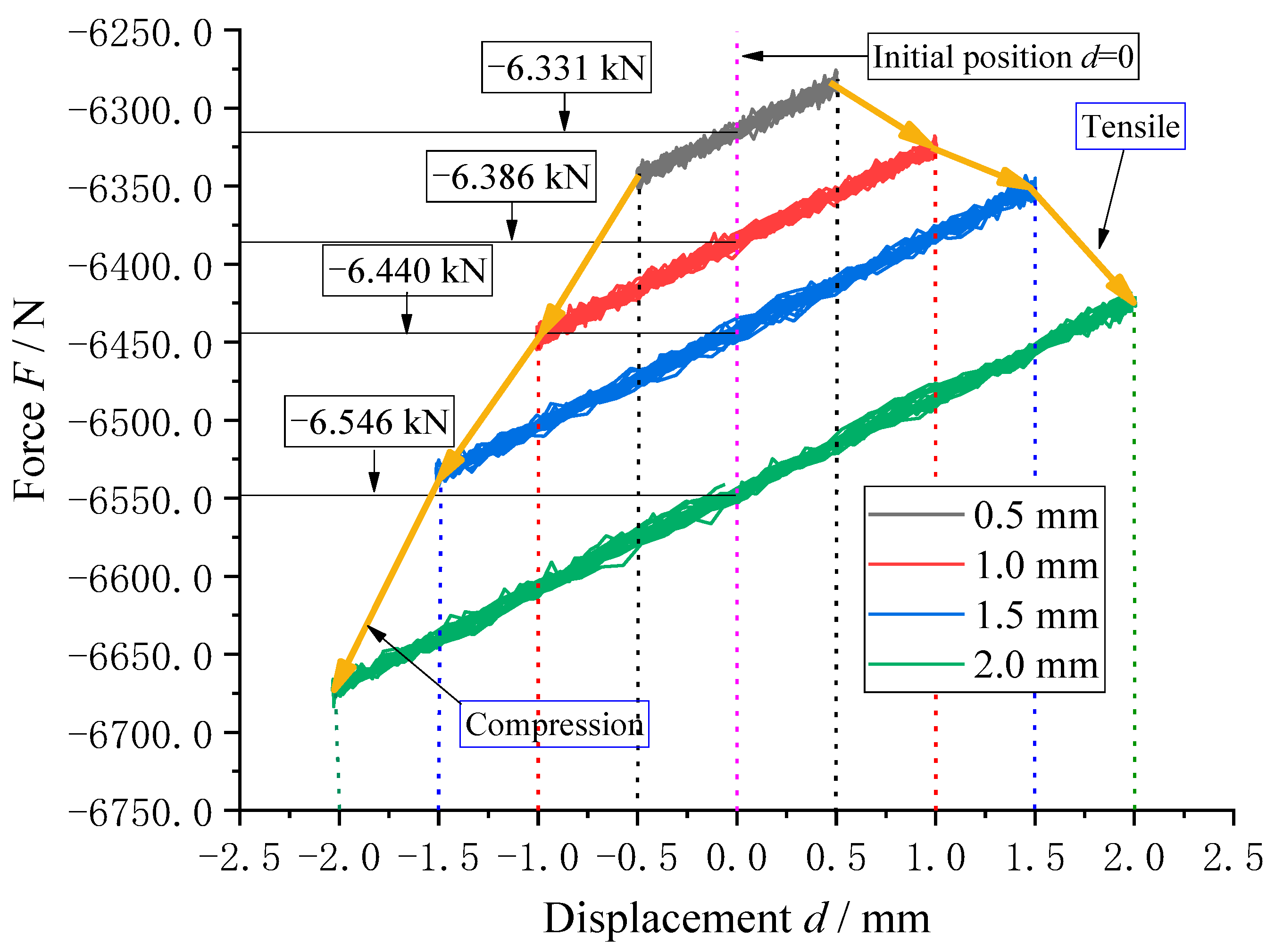
4.1.3. Effect of Different Amplitudes on Axial Load Characteristics of Air Spring

The impact of various excitation amplitudes on the axial load characteristics of the air spring was investigated under a constant initial pressure of 0.3 MPa and a fixed vibration frequency of 1.0 Hz. The results are presented in Figure 9, which reveals the variation in the air spring’s axial load over time.
As illustrated in Figure 9, with a 1.0 Hz excitation frequency and 0.3 MPa initial air pressure applied to the air spring, it was observed that the initial load values of the air spring differed significantly for different excitation amplitudes. The axial load exhibited distinct variation trends during the compression and tension cycles, with the compression cycle demonstrating a more significant change compared to the tension cycle.
The aforementioned research indicates that the stability of the axial load in an air spring can be enhanced by raising the frequency of excitation, and that the axial load capacity can be augmented by increasing the magnitude of excitation. This has been demonstrated through a thorough analysis and experimentation.

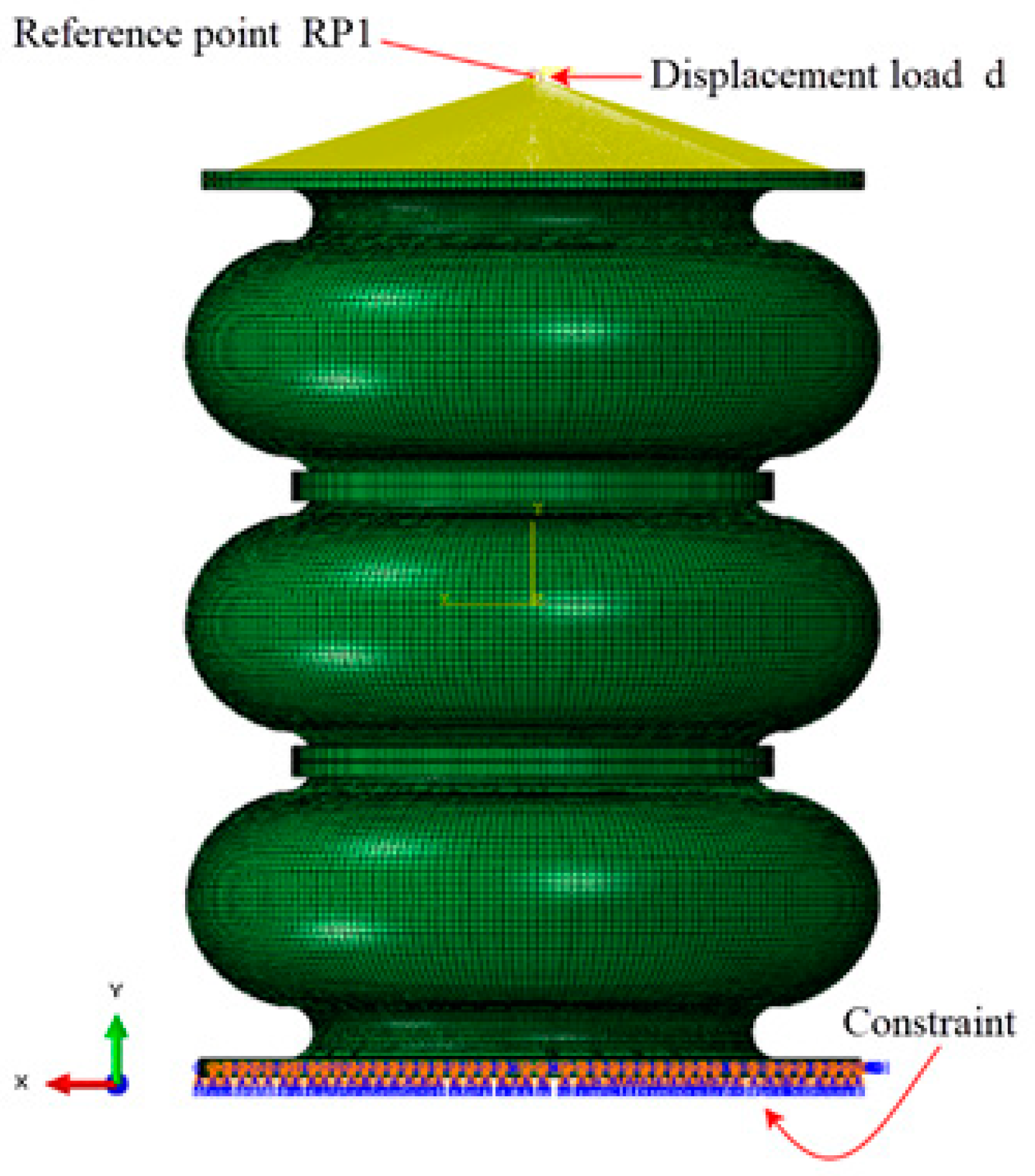
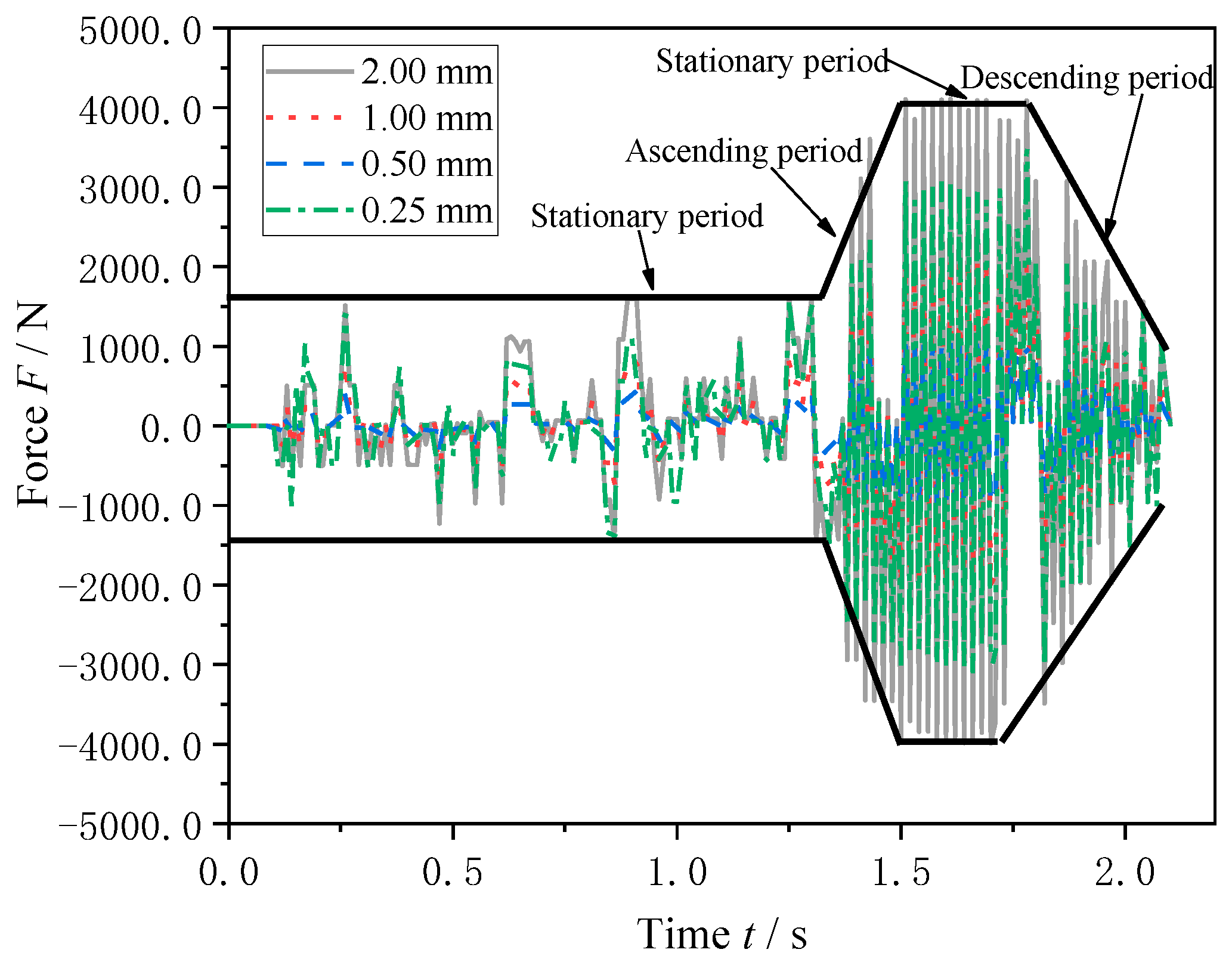
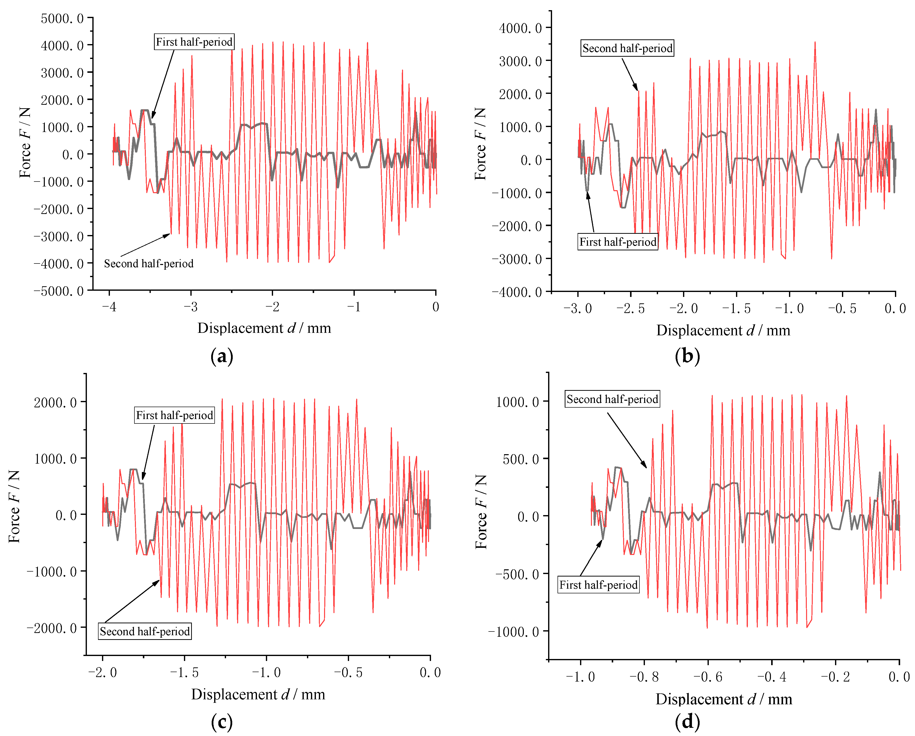
4.2. Radial Dynamic Mechanical Characteristics of the Air Spring

This study comprehensively examined the radial load stiffness of an air spring under a constant air pressure. A finite element simulation analysis was conducted to investigate the radial dynamic load characteristics of the air spring, utilizing various excitation amplitudes and frequencies in the radial direction. The bottom of the air spring was rigidly constrained, while the opposite end was flexibly connected to a reference point, to which radial displacement amplitude and frequency excitation loads were applied. The radial load and boundary conditions applied by the air spring in the radial direction are illustrated in Figure 10.

4.2.1. Influence of Amplitude Excitation on Radial Load Characteristics

In this experiment, an initial air pressure of 0.3 MPa was applied to the air spring, and a vibration frequency of 1.0 Hz was set for the reference point. The relationship between the axial load of the air spring and time was observed and recorded under excitation amplitudes of 0.25, 0.5, 1.0, and 2.0 mm. The results are displayed in Figure 11.
As depicted in Figure 11, the radial load of the air spring exhibited four distinct stages in response to varying excitation amplitudes: a stationary period, an ascending period, another stationary period, and a descending period. The peak value of the radial load generally increased with increasing amplitude; however, a deviation from this trend was observed when the excitation amplitude as set to 0.25 mm, as the peak radial load value surpassed that at an amplitude of 1.0 mm. This suggests that excitation amplitudes that are too low can have a negative impact on the radial load of the air spring.
To investigate the load characteristics of the air spring under varying excitation amplitudes, the reference point of the air spring was set to a vibration frequency of 1.0 Hz, and an initial inflation pressure of 0.3 MPa was applied. Figure 12 illustrates the relationship between the radial load of the air spring and vibration displacement for different amplitudes.
As demonstrated in Figure 12, under varying excitation amplitudes, the radial load of the air spring exhibited a similar pattern in the first half of each vibration cycle, characterized by fluctuations within a certain load amplitude. The excitation amplitude had a direct impact on the radial load peak, with higher amplitudes leading to greater peaks. The second half of each vibration cycle exhibited a regular and approximately symmetrical change, with peak loads that were relatively higher than those in the first half cycle. After a complete vibration cycle, the radial load tended to decrease steadily.

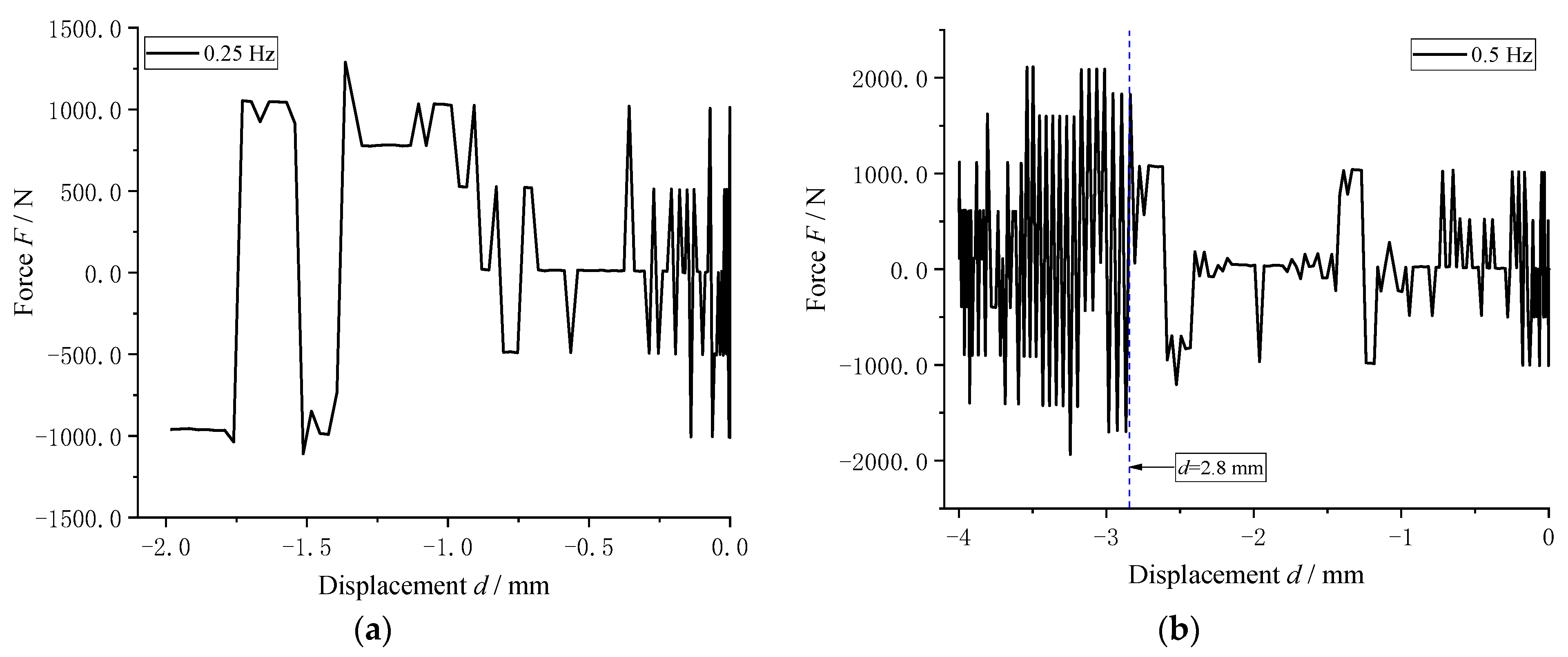
4.2.2. Influence of Excitation Frequency on Radial Load Characteristics

To examine the influence of the excitation frequency on the radial load characteristics of the air spring, the air spring was inflated with an initial air pressure of 0.3 MPa, and the reference point was subjected to radial excitations of 2 mm in amplitude, with excitation frequencies of 0.25, 0.5, 1.0, and 2.0 Hz. Figure 13 presents the relationship between the excitation frequency and the radial load of the air spring over time.
As depicted in Figure 13, the radial load behavior of the air spring was subject to variation as a result of different radial excitation frequencies. As time elapsed, the radial load peak values of the air spring prior to 1.2 s exhibited minimal variation and did not change insignificantly. However, after 1.2 s, the radial load peak values of the air spring exhibited significant variations with the increase in excitation frequency. The radial load peak value increased linearly with the increase in frequency. The maximum load peak values of the air spring at excitation frequencies of 0.25, 0.5, 1.0, and 2.0 Hz were recorded as 1.1, 2.1, 4.0, and 8.1 kN, respectively.
Figure 14 illustrates the change trend of the radial load of the air spring under an excitation amplitude of 2.0 mm and an initial air pressure of 0.3 MPa. The radial load was observed to vary as the air spring undergoes displacement vibration under different excitation frequencies. The study provides insight into the relationship between the radial load and displacement vibration under various excitation frequencies and serves as a valuable reference for further analyses of the radial dynamic mechanical characteristics of air springs.
As depicted in Figure 14, the radial load of the air spring exhibited significant variations in response to the changes in displacement. The radial load increased substantially when the displacement exceeded 2.8 mm. Upon closer examination of Figure 14c, it is apparent that there was a distinct difference between the first and second half cycles at a frequency of 1.0 Hz. The first half cycle exhibited a relatively moderate change in radial load, while the radial load peak in the second half cycle exhibited a noticeable increase and demonstrated a periodic variation trend.
As depicted in Figure 14, the radial load of the air spring exhibited distinct changes in response to varying excitation frequencies. The peak load of the air spring changed substantially with increasing displacement vibration. At frequencies of 1.0 Hz and 2.0 Hz, a significant difference was observed between the first and second half cycles of the vibration cycle, with the load change in the first half cycle being relatively moderate and the radial load peak of the air spring in the second half cycle displaying a significant increase with a periodic change trend. Additionally, at the 1/4 cycle and 2/4 cycle, the load of the air spring fluctuated within a similar amplitude range, while local fluctuations were observed in the 2/4 cycle. The regular radial load vibration began to emerge in the latter half of the 3/4 cycle and 4/4 cycle. The results of the analysis indicate that the excitation frequency has a significant impact on the radial load of the air spring and cannot be neglected.
This study presents a comprehensive examination of the dynamic load characteristics of air springs under low-frequency and low-amplitude excitations. The research was limited by the constraints of the experimental conditions and the inherent properties of superelastic materials. As a result, only the dynamic load behavior of air springs under these specific conditions was explored. This investigation of the dynamic mechanical properties of air springs under axial and radial loads offers a deeper understanding of the behavior of air springs under low-frequency and low-amplitude loads.

5. Conclusions

Based on fluid–structure coupling simulation method, the nonlinear dynamic mechanical characteristics of air springs were studied in this paper. An experimental platform was established to verify a numerical analysis model of air springs using the MTS testing machine, and a comprehensive investigation of the radial and axial dynamic mechanical behaviors of air springs was carried out. The results were obtained through a combination of quasistatic tension and compression tests and a dynamic radial vibration analysis. The key findings of the study are as follows:
(1)
The construction of the air spring experimental platform, based on the proposed experimental principle, was successful and the validity of the established numerical analysis model was demonstrated through experimentation. This serves as a solid foundation for future studies of dynamic load simulation analyses.
(2)
The results from the low-frequency and low-amplitude excitation experiments of the air spring in the axial direction, conducted on the established experimental platform, demonstrate the influence of low frequency and low amplitude on the axial load. The impact of low frequency and low amplitude was found to be more pronounced in axial compression.
(3)
The results of the radial dynamic simulation analysis of the air spring demonstrate that there is a significant increase in radial load with increasing frequency, highlighting the substantial impact of low-frequency excitation on the axial load of the air spring.
The results obtained from this study can provide valuable insights for future studies aimed at exploring the dynamic load characteristics of air springs under different excitation conditions. With advancements in experimental techniques and simulation analysis methods, it will be possible to expand the scope of this study and analyze the dynamic mechanical behavior of air springs under various combinations of low and high frequencies, as well as low- and high-amplitude interactions. The findings of this study will serve as a valuable reference for the optimization of damping parameters in air suspension systems, contributing to advancements in this subfield.

Author Contributions

Conceptualization, S.X. and T.Z.; methodology, Y.L.; validation, J.Z.; investigation, J.X.; writing—original draft preparation, Y.L.; writing—review and editing, Y.L.; funding acquisition, S.X., T.Z. and Y.L. All authors have read and agreed to the published version of the manuscript.

Funding

This research was funded by the National Natural Science Foundation Project of China, grant numbers 52175123 and 52172409, Key Technologies R&D Program of Henan Province, China, grant number 232102240092, and Sichuan Outstanding Youth Fund, China, grant number 2022JDJQ0025.

Institutional Review Board Statement

Not applicable.

Informed Consent Statement

Not applicable.

Data Availability Statement

The data presented in this study are available on request from the corresponding author. The data are not publicly available due to privacy.

Conflicts of Interest

The authors declare that they have no known competing financial interests or personal relationships that could have appeared to influence the work reported in this paper.

References

  1. Karpenkoa, M.; Skačkauskas, P.; Prentkovskis, O. Methodology for the Composite Tire Numerical Simula-tion Based on the Frequency Response Analysis. Eksploat. Niezawodn.-Maint. Reliab. 2023, 25, 1–11. [Google Scholar] [CrossRef]
  2. Skrickij, V.; Savitski, D.; Ivanov, V.; Skačkauskas, P. Investigation of Cavitation Process in Monotube Shock Absorber. Int. J Automot. Technol. 2018, 19, 801–810. [Google Scholar] [CrossRef]
  3. Wu, M.Y.; Li, X.B.; Yin, H.; Lu, J.C.; Wei, Y.T. Identification of Key Nonlinear Parameters and Research on Dynamic Characteristics of Air Spring Dynamic Stiffness Model. J. Mech. Eng. 2022, 58, 88–96. [Google Scholar]
  4. Quaglia, G.; Guala, A. Evaluation and validation of an air spring analytical model. Int. J. Fluid Power 2003, 4, 43–54. [Google Scholar] [CrossRef]
  5. Quaglia, G.; Sorli, M. Air suspension dimensionless analysis and design procedure. Veh. Syst. Dyn. 2001, 35, 443–475. [Google Scholar] [CrossRef]
  6. Chen, J.J.; Guo, K.H.; Yin, Z.H.; Wang, Q.Y.; Zhang, L. Research on Unified Model of Vertical Stiffness for Convoluted Air Spring. J. Mech. Eng. 2022, 58, 180–187. [Google Scholar]
  7. Tang, C.Y.; Zhang, Y.M.; Li, Y.G.; Zhao, G.Y.; Li, X. Analysis of Stiffness Characteristics and Influencing Factors Based on Single Chamber Cross-section Air Spring. J. Mech. Eng. 2014, 50, 137–144. [Google Scholar] [CrossRef]
  8. Zhang, Z.; Wang, J.; Wu, W.; Huang, C. Semi-active control of air suspension with auxiliary chamber subject to parameter uncertainties and time-delay. Int. J. Robust Nonlinear Control 2020, 30, 7130–7149. [Google Scholar] [CrossRef]
  9. Gokul, P.S.; Malar, M.K. Analytical approach for the design of convoluted air suspension and experimental validation. Acta Mech. Sin. 2019, 35, 1093–1103. [Google Scholar]
  10. Evans, J.R. Rail vehicle dynamic simulations using vampier. Veh. Syst. Dyn. 1999, 31, 119–140. [Google Scholar]
  11. Chen, Y.; Hou, Y.; Peterson, A.; Ahmadian, M. Failure mode and effects analysis of dual levelling valve airspring suspensions on truck dynamics. Veh. Syst. Dyn. 2019, 57, 617–635. [Google Scholar] [CrossRef]
  12. Ryaboy, V.M. Static and dynamic stability of pneumatic vibration isolators and systems of isolators. J. Sound Vib. 2014, 333, 31–51. [Google Scholar] [CrossRef]
  13. Li, Y.; He, L.; Shuai, C.-G.; Wang, C.-Y. Improved hybrid isolator with maglev actuator integrated in air spring for active-passive isolation of ship machinery vibration. J. Sound Vib. 2017, 407, 226–239. [Google Scholar] [CrossRef]
  14. Wu, X.W.; Chi, M.R.; Zhu, M.H.; Ceng, J.; Yang, F. Influences of air spring models on dynamics performance of railway vehicle. J. Traffic Transp. Eng. 2013, 13, 54–59. [Google Scholar]
  15. Mazzola, L.; Berg, M. Secondary Suspension of Railway Vehicle-Air Spring Modelling: Performance and Critical Issues. Proc. Inst. Mech. Eng. Part F J. Rail Rapid Transit 2014, 228, 225–241. [Google Scholar] [CrossRef]
  16. Qi, Z.; Wang, X.L.; Mo, R.L. Air Spring Modeling and Vehicle Dynamics Analysis Based on Fractional Calculus Theory. J. China Railw. Soc. 2021, 43, 67–76. [Google Scholar]
  17. Facchinetti, A.; Mazzola, L.; Alfi, S.; Bruni, S. Mathematical modeling of the secondary air spring suspension in railway vehicles and its effect on safety and ride comfort. Veh. Syst. Dyn. 2010, 48, 429–449. [Google Scholar] [CrossRef]
  18. Zeng, X.; Zhang, L.; Yu, Y.; Shi, M.; Zhou, J. The stiffness and damping characteristics of a dual-chamber air spring device applied to motion suppression of marine structures. Appl. Sci. 2016, 6, 74. [Google Scholar] [CrossRef]
  19. Li, X.; He, Y.; Liu, W.; Wei, Y. Research on the vertical stiffness of a rolling lobe air spring. Proc. Inst. Mech. Eng. Part F J. Rail Transit 2016, 230, 1172–1183. [Google Scholar] [CrossRef]
  20. Bhattacharyya, S.; Ghosh, A.; Basu, B. Nonlinear modeling and validation of air spring effects in a sealed tuned liquid column damper for structural control. J. Sound Vib. 2017, 410, 269–286. [Google Scholar] [CrossRef]
  21. Zargar, B.; Fahim, A.; Jnifene, A. Development, validation, and parameter sensitivity analyses of a nonlinear mathematical model of air springs. J. Vib. Control 2011, 08, 1777–1787. [Google Scholar] [CrossRef]
  22. Chen, J.J.; Yin, Z.H.; He, J.H.; Shangguan, W. Study on Modelling and Dynamic Characteristic of Air Spring with Throttling Damping Orifice and Auxiliary Chamber. J. Mech. Eng. 2017, 53, 166–174. [Google Scholar] [CrossRef]
  23. Lee, J.H.; Kim, K.J. Modeling of nonlinear complex stiffness of dual-chamber pneumatic spring for precision vibration isolations. J. Sound Vib. 2007, 301, 909–926. [Google Scholar] [CrossRef]
  24. de Melo, F.; Pereira, A.; Morais, A. The Simulation of an Automotive Air Spring Suspension Using a Pseudo-Dynamic Procedure. Appl. Sci. 2018, 8, 1049. [Google Scholar] [CrossRef]
  25. Chang, F.; Lu, Z.H. Dynamic model of an air spring and integration into a vehicle dynamics model. Proceedings of the institution of mechanical engineers. Part D-J. Automoble Eng. 2008, 222, 1713–1825. [Google Scholar]
  26. Zhu, H.; Yang, J.; Zhang, Y.; Feng, X.; Ma, Z. Nonlinear dynamic model of air spring with a damper for vehicle ride comfort. Nonlinear Dyn. 2017, 89, 1545–1568. [Google Scholar] [CrossRef]
  27. Zhu, H.; Yang, J.; Zhang, Y.; Feng, X. A novel air spring dynamic model with pneumatic thermodynamics, effective friction and viscoelastic damping. J. Sound Vib. 2017, 408, 87–104. [Google Scholar] [CrossRef]
  28. Ren, J.; Zhong, J.L. The accurate prediction method of tension modulus for nylon cord/rubber composite material. Appl. Mech. Mater. 2014, 575, 115–120. [Google Scholar] [CrossRef]
  29. Levin, V.; Zingerman, K.; Vershinin, A.; Yakovlev, M. Numerical analysis of effective mechanical properties of rubber-cord composites under finite strains. Compos. Struct. 2015, 13, 25–26. [Google Scholar] [CrossRef]
  30. Yuan, C.Y.; Zhou, K.K.; Wu, L.Q. Structural Analysis Method of automotive air-spring rubber air-bag. J. Mech. Eng. 2009, 45, 221–225. [Google Scholar] [CrossRef]
  31. Liu, Z.B.; Xiao, S.N.; Luo, S.H. Simulation of Airbag Ejection Acceleration Process on a Train Collision Testbed. J. Southwest Jiaotong Univ. 2017, 52, 127–132. [Google Scholar]
  32. Li, Z.Z.; Zhu, T.; Xiao, S.N.; Zhang, J.K.; Wang, X.R.; Ding, H.X. Simulation method for train curve derailment collision and the effect of curve radius on collision response. Proc. Inst. Mech. Eng. Part F J. Rail Rapid Transit 2023, 237, 1130–1139. [Google Scholar] [CrossRef]
  33. Zhu, T.; Ding, H.; Wang, C.; Liu, Y.; Xiao, S.; Yang, G.; Yang, B. Parameters calibration of the GISSMO failure model for SUS301L-MT. Chin. J. Mech. Eng. 2023, 36, 20. [Google Scholar] [CrossRef]
  34. Li, Y.; Xiao, S.; Yang, B.; Zhu, T.; Yang, G.; Xiao, S. Study on the influence factors of impact ejection performance for flexible airbag. Adv. Mech. Eng. 2018, 10, 1687814018807333. [Google Scholar] [CrossRef]
  35. Li, Y.R.; Yang, B.; Xie, J.K. Study of Influence Factors on Ejection Impact Performance of Air Spring. J. Mech. Eng. 2020, 56, 144–153. [Google Scholar]
  36. Li, Y.R.; Xiao, S.N.; Xie, J.K.; Zhu, T.; Yang, B.; Yang, G.W.; Xiao, S.D. Influence of Cord Parameters on the Load Characteristics of Airbags. Shock Vib. 2021, 2021, 8670882. [Google Scholar] [CrossRef]
  37. Dijk, R.; Keulen, F.; Sterk, J.C. Simulation of closed thin-walled structures partially filled with fluid. Int. J. Solids Struct. 2000, 37, 6063–6083. [Google Scholar] [CrossRef]
  38. Berry, D. Formulation and Experimental Verification of Pneumatic and Hydraulic Finite Elements; Indiana Purdue University: West Lafayette, IN, USA, 1994. [Google Scholar]
  39. Hiremath, S.S.; Singaperumal, M. Investigations on actuator dynamics through theoretical and finite element approach. Math. Probl. Eng. 2010, 2010, 191898. [Google Scholar] [CrossRef]
  40. Liu, Q.F.; Zhang, Z.G.; Wang, Y.; Zheng, H.X.; Xie, J.L. Finite Element Calculation of the Nonlinear Lateral Characteristic of Air Spring. J. China Railw. Soc. 2015, 37, 29–33. [Google Scholar]
  41. Mooney, M. A theory of large elastic deformation. J. Appl. Phys. 2004, 11, 582–592. [Google Scholar] [CrossRef]
Figure 1. The flow cavity structure diagram.
Applsci 13 12677 g001
Figure 2. Air spring and cord distribution diagram.
Applsci 13 12677 g002
Figure 3. Experimental principle of air spring.
Applsci 13 12677 g003
Figure 4. Test equipment for air spring.
Applsci 13 12677 g004
Figure 5. Comparison results of air spring load.
Applsci 13 12677 g005
Figure 6. Test simulation comparison results of air spring pressure.
Applsci 13 12677 g006
Figure 7. (a) Load change when the vibration frequency is 0.25 Hz; (b) load change when the vibration frequency is 0.25 Hz; (c) load change when the vibration frequency is 0.75 Hz; (d) load change when the vibration frequency is 1.0 Hz.
Applsci 13 12677 g007
Figure 8. (a) The load changes when the amplitude is 0.5 mm; (b) the load changes when the amplitude is 1.0 mm; (c) the load changes when the amplitude is 1.5 mm; (d) the load changes when the amplitude is 2.0 mm.
Applsci 13 12677 g008
Figure 9. Vibration characteristics of air spring with displacement under different amplitudes.
Applsci 13 12677 g009
Figure 10. Radial load and constraint diagram of air spring.
Applsci 13 12677 g010
Figure 11. Variation in air spring load over time under radial amplitude excitation.
Applsci 13 12677 g011
Figure 12. (a) Change in load with displacement when amplitude is 2.0 mm; (b) change in load with displacement when amplitude is 2.0 mm; (c) change in load with displacement when amplitude is 1.5 mm; (d) change in load with displacement when amplitude is 0.5 mm.
Applsci 13 12677 g012
Figure 13. Variation in radial load of air spring over time under different excitation frequencies.
Applsci 13 12677 g013
Figure 14. (a) Load variation at 0.25 Hz excitation frequency; (b) load variation at 0.50 Hz excitation frequency; (c) load variation at 1.0 Hz excitation frequency; (d) load variation at 2.0 Hz excitation frequency.
Applsci 13 12677 g014aApplsci 13 12677 g014b
Table 1. Mooney–Rivlin model parameters.
Rubber ParametersCord Parameters
C10C01D ρ (t/mm3)E/MPa μ ρ (t/mm3) Rebar Angle/°
7.23.201.19 × 10−925000.41.19 × 10−950
Table 2. Distribution parameters of air spring cord.
CordRebar Angle θ/°Spacing d1/mmCord Diameter φ/mmPosition of Rebar d2/mm
First cord
Second cord
50
−50
1.5
1.5
0.5
0.5
1
−1
Disclaimer/Publisher’s Note: The statements, opinions and data contained in all publications are solely those of the individual author(s) and contributor(s) and not of MDPI and/or the editor(s). MDPI and/or the editor(s) disclaim responsibility for any injury to people or property resulting from any ideas, methods, instructions or products referred to in the content.

