Article

Influence of Lower Lateral Bracing on the Seismic Pounding Damage to Slab-On-Girder Steel Bridges

School of Civil and Transportation Engineering, Hebei University of Technology, Tianjin 300401, China
*
Author to whom correspondence should be addressed.
Appl. Sci. 2023, 13(23), 12787; https://doi.org/10.3390/app132312787
Submission received: 26 September 2023 / Revised: 27 November 2023 / Accepted: 27 November 2023 / Published: 29 November 2023
(This article belongs to the Section Civil Engineering)

Abstract

:
During strong seismic events, seismic-induced pounding has been observed to cause damage to bridges. Previous studies on seismic-induced bridge pounding responses have generally focused on reinforced concrete bridges. However, the seismic damage between steel and reinforced concrete beams is significantly different, and research on steel beams’ seismic pounding response remains limited. Therefore, this paper adopts the multiscale fine three-dimensional numerical simulation method to study the seismic response of a slab-on-girder steel bridge. The numerical results show that the lower lateral bracing has a significant effect on seismic damage to steel beams. The lower lateral bracing can share about 1/3 of the pounding action and reduce the displacement angle of the steel beam by 40%. Under horizontal two-way seismic action, the lower lateral bracing significantly reduces the stress on the steel beam. In addition, the bracing should have continuous stiffeners to avoid connection failure. Generally, the lower lateral bracing should be considered in the design of the slab-on-girder steel bridge. It significantly improves the lateral seismic performance of the bridge and reduces seismic damage to steel beams.

1. Introduction

During strong seismic events, adjacent structures tend to pound with each other, and the large pounding force significantly alters the dynamic behavior of the adjacent structures. Whether to buildings [1] or bridges [2], seismic-induced pounding can cause structural damage (even serious damage under large seismic activity). Some new characteristics were observed in the steel bridges’ seismic damage in the 2016 Kumamoto earthquake [3]. As shown in Figure 1, typical seismic damage to steel bridges includes steel beam damage and lower lateral bracing buckling. Seismic-induced pounding is closely related to these seismic damages, and the lower lateral bracing influences the beam’s damage.
Some scholars have paid attention to the seismic pounding effects of bridges. Bi et al. [4] studied the combined effects of ground motion spatial variation, local site amplification, and soil–structure interaction on the seismic-induced pounding failure of bridges and estimated the separation distance that expansion joints need to provide. Jankowski [5] studied the pounding between the superstructure segments of an elevated highway bridge with a three-span continuous deck under three-dimensional nonuniform earthquake excitation. Li et al. [6] studied the adjacent pounding effect of a midspan curved bridge with a longitudinal slope and analyzed the influence of connection parameters such as gap size and longitudinal slope. These studies analyzed the influencing factors of the seismic pounding response of bridges from the perspectives of different bridge structural forms and seismic effects. However, the models used in these studies are simplified, making it difficult to determine the damage caused by seismic poundings.
In recent years, the study of the seismic pounding response of bridges has developed in a more refined direction. Bi and Hao [7], for example, used a refined 3D finite element model to study the seismic pounding damage to a two-span bridge model without or with shear keys and concluded that neglecting shear keys in bridge seismic response analysis may lead to inaccurate predictions. Yang et al. [8] presented an experimental study on the transverse pounding reduction of a high-speed railway simple-supported girder bridge. Xu et al. [9] proposed a new type of shear key for the retrofit of existing highway bridges and further studied their seismic pounding damage under repeated monotonic loading. Meng et al. [10] studied the performance of steel keys in seismic pounding events of bridges via shake table experiments and discussed the influence of gap size. These studies further discussed the problem of bridge pounding damage in further detail through refined finite element models and experiments. The lateral seismic pounding effect must be transmitted from the shear keys to the beam and bracing, and a detailed consideration of the shear keys is conducive to a more accurate calculation of the beam’s damage. However, the above studies still ignore the damage to the lower lateral bracing under the action of seismic pounding and do not realize the natural advantages of lower lateral bracing in controlling the damage to steel beams. Some scholars have proposed different measures to reduce the beam’s pounding damage from the perspective of increasing damping devices, such as placing hard rubber bumpers [11], magnetorheological dampers [12], and rotational friction hinge dampers [13]. These measures have proven effective, but placing many dampers will inevitably significantly increase the seismic design cost of the bridge and also bring inconvenience in long-term maintenance. In fact, from the perspective of seismic damage to steel bridges, well-designed lower lateral bracing has the characteristics of reducing the pounding damage to steel beams. Therefore, it is necessary to further clarify the influence of lower lateral bracing on the seismic pounding damage to slab-on-girder steel bridges.
Especially after the Kumamoto earthquake, the seismic performance of and damage to the lower lateral bracing of the slab-on-girder steel bridges have been paid attention to by scholars. Won et al. [14], for example, studied the seismic-induced pounding effect on bridge beams and piers by analyzing the dynamic response of a three-span simply supported steel girder bridge. Zheng et al. [15] evaluated the pounding interaction between bridge abutments and steel beams under nonuniform seismic excitation. Aye et al. [16] discussed the damage survey of the Tawarayama Bridge affected by the Kumamoto earthquake, especially about its lower lateral bracing’s severe damage by the earthquake. Mustafa and Miki [17] found that the bottom plate of the end steel beam will rotate inward under the action of an earthquake and damage will occur at the connection with lower lateral bracing. These studies considered the lower lateral bracing member in the bridge models. However, none of these studies focused on the details exhibited by the steel bridges’ seismic damage. The above seismic pounding studies of steel bridges are insufficient, especially ignoring the precise geometric dimensions and connection relationship between steel beams and lower lateral bracings, which makes it difficult to explain the seismic damage to steel bridges and to clarify the control effect of the lower lateral bracings on the damage to the steel beams.
Therefore, some challenges remain for slab-on-girder steel bridges: (1) special seismic damage to steel bridges needs to be studied, such as steel beam webs’ lateral deformation and lower lateral bracings’ vertical failure, according to lessons learned from the Kumamoto earthquake; (2) the transverse stiffness of steel beams is low and uneven along the beam height; thus, their lateral damage may be serious under seismic pounding, and the damage scope is not clear; (3) the effectiveness of the lateral bracings has not been clarified for steel beams, especially considering their encounter plastic and buckling deformation; (4) since the seismic-induced pounding process of steel bridges involves the elastoplastic of steel, buckling of steel components, and contact of keys (i.e., material, geometry, and boundary nonlinearity), multiscale refined numerical simulation methods must be adopted. Therefore, it is necessary to further study the seismic response and influence of lower lateral bracing for slab-on-girder steel bridges.
To solve the above problems, the influence of lower lateral bracing on the seismic pounding damage to slab-on-girder steel bridges is studied in detail by using a refined finite element model. The main differences between the aim of this paper and other studies are as follows: (1) the role of lower lateral bracing in the case of the seismic pounding of slab-on-girder steel bridge is analyzed, which has been ignored or oversimplified in previous studies; (2) possible failure modes and engineering design recommendations for the lower lateral bracing are further proposed.
This paper is organized as follows. Section 1 introduces the background and motivations. Section 2 illustrates the modeling method of the bridge’s numerical model and the selection of the ground motions. In Section 3, the simulation results of the seismic-induced pounding failure of the steel bridge are presented and discussed in detail. The contribution of lower lateral bracing to the seismic performance of steel beams is discussed in Section 4. Finally, in Section 5, the main conclusions are drawn.

2. Bridge Model and Ground Motion
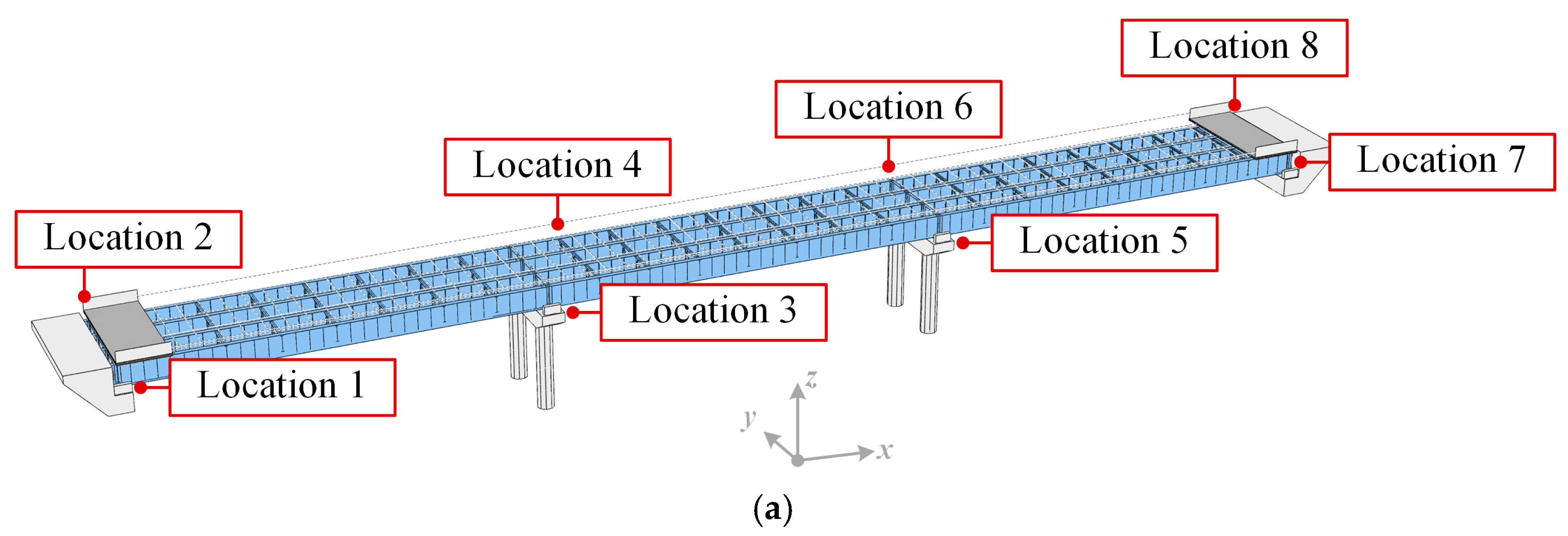
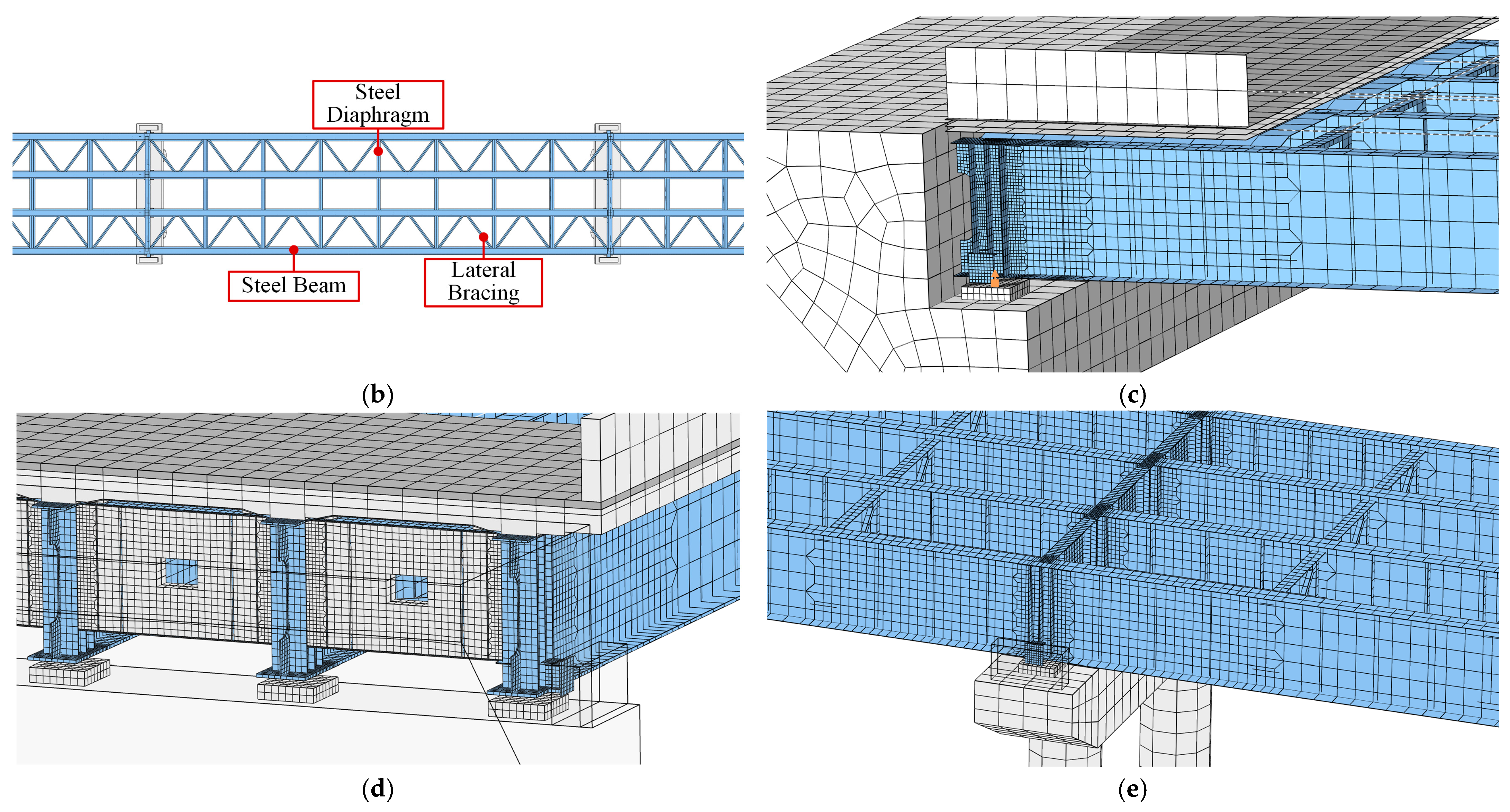
2.1. Bridge Model

The continuous slab-on-girder steel bridge considered in this paper is located on the Yanqing-Chongli Highway in China, which was completed in 2020 and served the traffic needs of the Olympic Winter Games Beijing 2022. A view of the bridge is shown in Figure 2. This bridge is a typical slab-on-girder steel bridge with a total length of 120 m. The bridge’s superstructure comprises continuous steel–concrete I-beams, and its substructure comprises ribbed abutments, double-column piers, and pile foundations.
Figure 3 shows the layout and dimensions of this slab-on-girder steel bridge. As shown in Figure 3a, the bridge is divided into three spans of 40 m each. The two sides of the girder are supported by two abutments and the middle by two piers. It is worth noting that the girder contains four three-span continuous steel beams and the outer stiffeners above all bearings are attached steel keys. The piers are double-column circular piers with a height of 8.5 m. Gaps of 80 mm were introduced between the abutments and the bridges to avoid binding forces on the girders due to longitudinal deformations caused by temperature fluctuations, traffic loads, etc. This type of gap is denoted as Gap A in Figure 3. The cross-section of the bridge is shown in Figure 3b, in which there are four steel I-beams with a height of 2.05 m and spacing of 3.3 m. The steel beams are welded from the top, bottom, and web plates with variable thicknesses, which are 27, 40, and 13 mm thick. The transverse connection between the steel beams is reinforced by steel frame diaphragms. The bridge deck is made of reinforced concrete; the thickness of the standard section is 25 cm, and the steel beam support area is thickened to 35 cm. To prevent the bridge from falling due to beam failure during a seismic event, steel shear keys are provided at both ends of the side beams, and concrete shear keys are set at both ends of the abutments and cover beams. Gaps of 50 mm were introduced between the steel and concrete shear keys; this type of gap is denoted as Gap B in Figure 3.
In addition, 16 road bridge basin bearings (GPZ 2009) are set on the abutments and cover beams to support all steel beams. They are four unidirectional movable bearings and twelve bidirectional movable bearings, each with a movement of ±10 cm. Concrete bearing pads are set under all bearings to homogenize the transfer of the upper load. Detailed dimensions of the abutment at the bearing are shown in Figure 3c. The detailed dimensions of the cover beam and pier at the bearing are shown in Figure 3d,e.

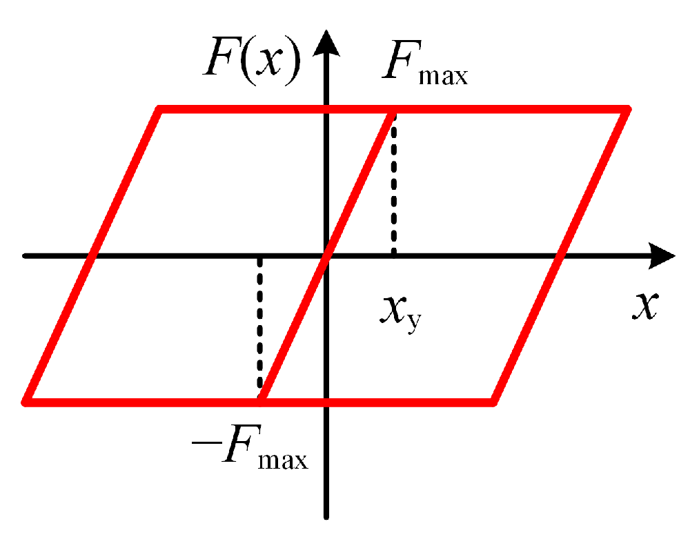
2.2. Element and Material Properties

The finite element model was established and implicit dynamics analysis were performed using the general finite element software Abaqus [18]. To fine-simulate the seismic behavior of and local damage to the slab-on-girder steel bridge, plate elements are used for the steel beams and bridge deck, and solid elements are used for abutments and pier columns. However, this fined model is computationally expensive; as such, further adoption of a multiscale model is a better solution [19]. In this model, plate elements are used to simulate steel beams that may undergo local deformation; beam elements are used to simulate the concrete bridge deck. The space grillage method was used to model the beam model to ensure the continuous stiffness of the bridge deck in all directions. At the interface of the plate and beam elements, the transmission of translational and rotational degrees of freedom was handled according to the principles of displacement coordination and flat section, respectively. The interface and deformation relationship between the two elements is shown in Figure 4. In this study, the contact relationship between steel beams and the concrete bridge deck is simulated based on the hypothesis of tight bonding; that is, it is considered that the two do not produce relative slip and adopt the tie constraint. For concrete beams and steel beams in the model, there is a binding connection between the two parts. Since the pounding only occurs at the beam ends, the beam in the middle part always remains elastic, this simplification is reasonable.
A global diagram of the bridge FE model is shown in Figure 5a. The eight key positions of the bridge model are named Locations 1 to 8 for convenience. The components of the corresponding locations are also named Gap A 1, Steel Key 2, etc. Figure 5b shows a top view of the bridge model, revealing the positional relationships of steel beams, steel diaphragms, and lateral bracings.
In addition, the meshing size of the plate element was carefully considered. Numerical convergence tests on multiple mesh sizes (25, 50, and 100 mm) revealed that the results from 50 mm and smaller mesh were similar but computationally inexpensive. To keep the calculation cost as low as possible, the 50 mm finest mesh was only suitable for the length range of a steel beam 0.25 m from the steel beam’s ends. The fine mesh (100 mm), medium mesh (200 mm), and rough mesh (500 mm) were also set in the model. Figure 5c–e shows the scheme of gradient mesh sizes at different positions, respectively.
The steel beam adopts Q345qE steel, which is a low-alloy high-strength structural steel commonly used in China, with a yield strength of not less than 345 MPa. For the simulation of the beam steel (Q345qE), a high-precision hysteresis constitutive model was adopted, considering the mixed hardening effect of steel. The constitutive model includes nonlinear isotropic and kinematic hardening. Researchers have widely used this constitutive model, which has proven to be a good predictor of nonlinear mechanical responses in steel [20]. Table 1 shows the material parameters of the steel material [21]. The Young’s modulus, density, and Poisson’s ratio of the steel material are 2.06 × 10⁵ MPa, 7850 kg/m3, and 0.2, respectively. In this study, since the main focus is on the seismic-induced pounding failure of steel beams, only the elastic behavior of concrete materials is considered. The Young’s modulus, density, and Poisson’s ratio of the concrete material are 3.45 × 10⁴, 2600 kg/m3, and 0.2, respectively.

2.3. Contact and Boundary Conditions
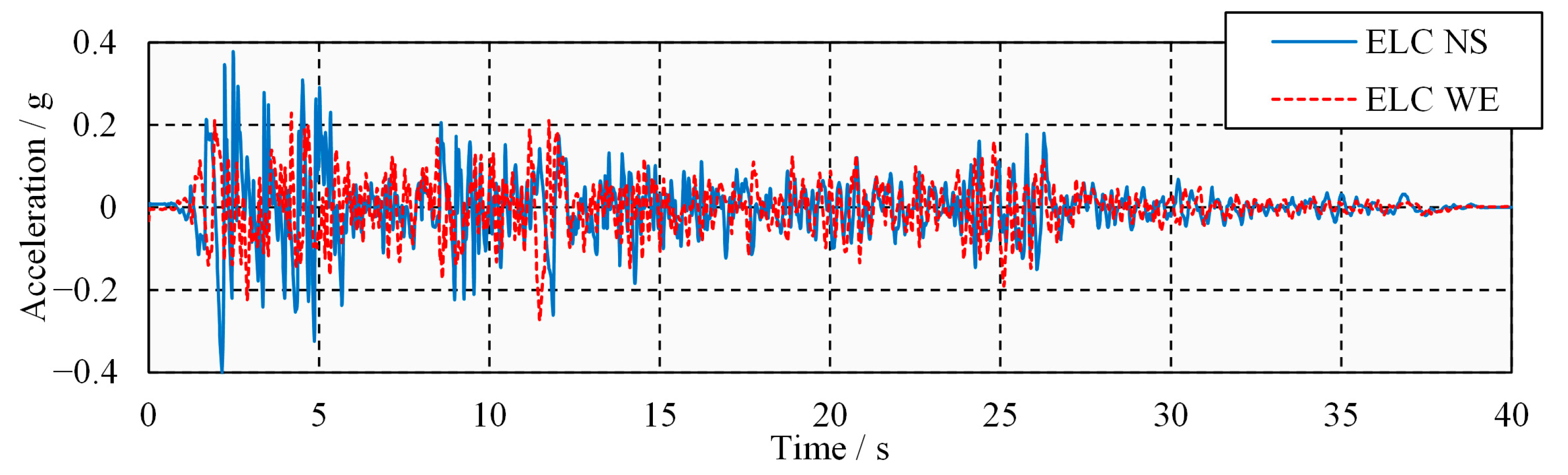
The general contact relationship was established to achieve free contact between the three-dimensional point-to-surface and surface-to-surface, for beam ends and shear keys, which may cause a seismic pounding response. The general contact behavior consisted of normal and tangential contact behavior. The penalty function method was adopted to establish the “normal hard contact” relationship for the contact interface and the separation after contact was allowed. Isotropic penalty friction was considered for tangential behavior, and the friction coefficient between the steel plate and concrete surface was 0.4 [22]. The position affected by the contact force was spatially arbitrary rather than a priori using this contact scheme.
The bearing’s force–displacement relationship was simulated using the elastic-damping connecting element. The upper and lower nodes of the connecting element are constrained by a multipoint (beam type) with the bearing area of the steel beam bottom and concrete bearing pads, respectively. There is a nonlinear mechanical relationship between the upper and lower nodes. As shown in Figure 6, the force–displacement relationship of a movable basin bearing can be expressed as the bilinear ideal elastoplastic model.
The bearing’s critical sliding friction and initial stiffness are calculated according to Equations (1) and (2):
Fmax = μd × R
k = Fmax/xy
where Fmax is the critical sliding friction of the bearing (kN), μd is the sliding friction coefficient (generally 0.02), R is the gravity of the superstructure undertaken by the bearing (kN), k is the initial stiffness of the bearing (kN/m), and xy is the yield displacement (m) of the movable basin support (generally, 0.002~0.005 m).
In this study, the contact relationship between the steel beams and the concrete bridge deck is simulated based on the hypothesis of tight bonding; that is, it is considered that the two do not produce relative slip and adopt the tie constraint. It can be assumed that the abutments are rigidly fixed on the ground to focus on the seismic-induced pounding damage to the steel bridge. Therefore, the soil is ignored in the model and the bottom of the piers and abutments maintain fixed boundary conditions.
The boundary conditions and applied loads of the finite element model can be further summarized in combination with the two-step dynamic analysis process. Before the analysis began, fixed boundary conditions were applied to the bottom of the piers and abutments. In the first analysis step, a gravity load was applied to the model in the negative z direction, maintaining fixed boundary conditions. In the second analysis step, the applied gravity load was maintained, but the displacement restrictions in the x and y directions were lifted, and the ground motion records were imposed on the corresponding directions as acceleration boundary conditions. In this paper, the material, geometry, and contact nonlinearities of the model were all considered.

2.4. Ground Motions

According to the ground soil conditions of the bridge site, records of representative ground motion acceleration with far and near faults were selected as the input boundary conditions for time history analysis. Following Baker’s suggestions [23], ground motion records from the Station El Centro Array #9 (hereinafter referred to as ELC) in the Imperial Valley Earthquake (1979) were selected as input conditions. Further considering the numerical convergence and computational cost, this study focuses on the horizontal seismic response of the slab-on-girder steel bridge. Therefore, the records of the horizontal NS and WE components were used as input boundary conditions in longitudinal (x direction) and transverse (y direction) for the bridge model. Note that all the ground motion records have no relationship with the seismic design of the completed bridge; further, they were selected to observe the severe seismic damage of the slab-on-girder steel bridge. To facilitate the comparison of bridges’ seismic responses, the peak ground acceleration (PGA) of the station was scaled to 0.4 times the gravity acceleration (0.4 g). Then, the PGA of the ELC’s NS and WE components were 0.40 and 0.28 g, respectively. Figure 7 shows the amplitude scaling ground motion time history records of ELC.

3. Numerical Results

3.1. Validation of the Model

Figure 8 shows the numerical convergence of the finite element model. Since the problem studied is the dynamic problem of a composite structure, the maximum deflection of the steel beam is taken as a function of the number of elements, and the relative error of the maximum deflection and the relative calculation time are plotted, respectively. It can be seen that, with the increase in the number of elements, the relative error gradually decreases, and the calculation time increases rapidly. It is generally believed that more accurate results are obtained with more elements, but if the number of elements is too large, the calculation time will increase to an unacceptable level. Too few elements cannot reasonably reflect the deformation of the steel beam, resulting in a large error. Considering the interrelationship between the error and time, the model scheme with 91,513 elements is adopted, which can obtain sufficiently accurate results in an acceptable calculation time, and the calculation time and accuracy can be well-balanced.
In order to further confirm the rationality of the finite element model, the first three-order vertical natural frequencies and modes of the bridge in Figure 2 were obtained with an ambient vibration test and compared with the simulation results. The results of the comparison are summarized in Table 2 and Figure 9. It can be seen that the relative error of the frequencies in the test and simulation is small, and the finite element model correctly reflects the vertical natural modes of the bridge. The results above show that the finite element model can accurately reflect the dynamic response of the actual bridge.

3.2. Response under Transverse Seismic Actions

Under the effect of the transverse seismic actions, the steel keys on the steel beams’ sides pound with the concrete keys on the abutments and piers. At the time of pounding, the huge impact force is transferred to the steel beams through the steel block and leads to its damage. The stress state of the steel beam at the time of pounding is shown in Figure 10. It can be seen that the steel beam without lower lateral bracing produces a larger high-stress zone at the time of pounding. Specifically, all the damages to the steel beams without lower lateral bracing are concentrated at the location of the keys on the side beams (at position A in Figure 10). The center beams bear almost no lateral force (at position B in Figure 10). In contrast, for the steel beam with lower lateral bracing, the damage at the key location on the side beam is mitigated because the lower lateral bracing partially transfers the pounding force from location A to location B on the center beam. The lateral pounding damage of the steel beam was significantly mitigated due to the sharing and transfer of the pounding force by the lower lateral bracing.
The transverse seismic pounding causes the steel beam to experience high stress and also leads to the residual deformation of the steel beam. As shown in Figure 11a, under the transverse pounding force, the steel beam will be deformed by rotations inward. Since the stress of the steel beam under pounding will exceed the elastic limit of the steel, the rotational deformation at the bottom of the beam is irreversible. After the end of the seismic action, the displacement angle between the top and bottom plates of the beam is shown in Figure 11b. It can be seen that due to the sharing of the pounding force by the lower lateral bracing and the enhancement of the transverse stiffness of the steel beam, the displacement angle of the bracing steel beam is significantly smaller than that of the non-bracing steel beam. In addition, at the pier and abutment positions, the lower lateral bracing can significantly reduce the displacement angle of the beam to 40% of the original one.
The stress time history of the steel beam and the lower lateral bracing is shown in Figure 12a, and it can be seen that a pounding occurred at 12.3 s. The pounding caused stress peaks of 464 MPa, 437 MPa, and 242 MPa for the steel beam without lower lateral bracing, the steel beam with lower lateral bracing, and the lower lateral bracing, respectively. After the pounding, the residual stresses of the steel beam without lower lateral bracing, the steel beam with lower lateral bracing, and the lower lateral bracing were 371 MPa, 249 MPa, and 97 MPa, respectively. The residual stress of the steel beam with lower lateral bracing and the lower lateral bracing to the steel beam without lower lateral bracing accounted for 67% and 26%, respectively; that is, lower lateral bracing shared about 1/3 of the pounding impact. Moreover, the stress peak of the lower lateral bracing does not exceed the elastic limit of the steel when experiencing a pounding, and it always remains elastic under the action of earthquakes. The stress cloud diagram of the lower lateral bracing at the time of pounding is shown in Figure 12b, and it can be seen that the high-stress zone is mainly the bracing’s connection with the side beam.

3.3. Response under Horizontal Bidirectional Seismic Actions

Under horizontal two-way seismic actions, due to the rotation of the bridge deck, the steel beam does not pound uniformly with all the keys on the abutment and piers but concentrates on the keys at the corner points. In addition, due to the coupling of longitudinal and transverse seismic effects, the seismic response of the bridge is greater. In this paper, horizontal bidirectional seismic action is considered as simultaneously input accelerating time histories along the longitudinal (x direction) and transverse (y direction) directions to calculate the seismic response of the bridge. The seismic acceleration time history in the x direction is the NS component of the ELC, and the seismic acceleration time history in the y direction is the WE component of the ELC.
The relative displacement of the steel beam at the bearing is shown in Figure 13. It can be seen that the relative displacement of the beam, represented by the results of Position 1 and Position 8, does not exceed the displacement limit of the bearing. So, the beam will not slip off the bearing under the action of earthquakes. The seismic pounding damage to steel beams can be further analyzed under this premise.
Figure 14 shows the stress cloud of the bridge in the event of a lateral pounding, and it can be seen that the pounding damage of the steel beam is more serious under horizontal two-way seismic actions. The damaged areas of the steel beam without lower lateral bracing include webs, beam ends, supporting stiffeners, and steel keys. The damage to the steel beam with lower lateral bracing includes only webs, supporting stiffeners, and steel keys in direct contact with the steel keys. From the perspective of the damaged area, the lower lateral bracing effectively reduces the damaged area of the steel web.
Figure 15 shows the stress distribution of the steel web along the beam height under its own weight at the time of the pounding and after the earthquake. It can be seen that the stress distribution of steel beams is significantly amplified due to seismic action. As shown in Figure 15b, from the results of the peak stress, the stress of the two steel beams at the steel key exceeded the elastic limit at the time of the pounding, but the stress of the steel beam with lower lateral bracing was always less than the stress of the steel beam without lower lateral bracing. The stress of the steel beam with lower lateral bracing at the steel key is 89% of that of the steel beam without lower lateral bracing, while the stress of the steel beam with lower lateral bracing in other parts is only 41% of that of the steel beam without lower lateral bracing on average. After the end of the seismic action, the distribution of residual stress showed a similar phenomenon. As shown in Figure 15c, the residual stress of the steel beam with lower lateral bracing at the steel key is 90% of that of the steel beam without lower lateral bracing, while the residual stress of the steel beam with lower lateral bracing in other parts is only 32% of the steel beam without lower lateral bracing on average. Although the lower lateral bracing only slightly reduces the stress at the key, it significantly reduces the stress on other parts of the steel beam.
The vertical displacement and stress time history of the lower lateral bracing are further plotted in Figure 16. The reference point of vertical displacement is the midpoint of the lower lateral bracing, and the reference point of the stress is the connection point of the lower lateral bracing and the steel beam. It can be seen that when the pounding occurs, the stress peak occurs at the connection between the lower lateral bracing and the steel beam, and the lower lateral bracing has an upward vertical displacement. After the end of the seismic action, there is still residual stress at the connection between the lower lateral bracing and the steel beam, and the vertical displacement of the lower lateral bracing cannot be restored. The lower lateral bracing remains elastic throughout the seismic action, and the residual vertical displacement is due to its elastic bending. However, these high-strain low-cycle loads may significantly reduce the fatigue resistance and weld performance of the bracing.

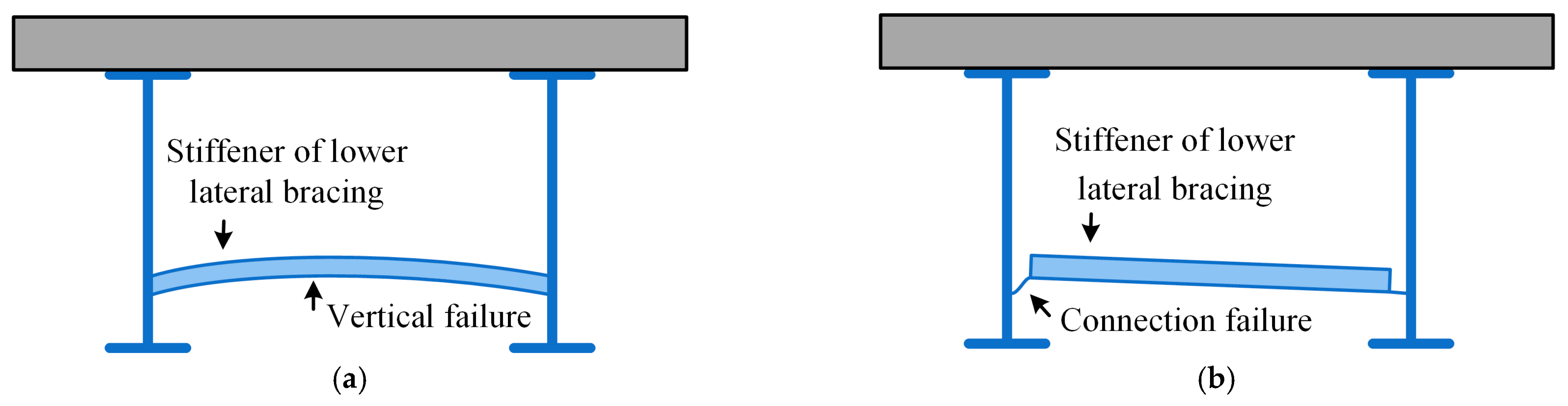
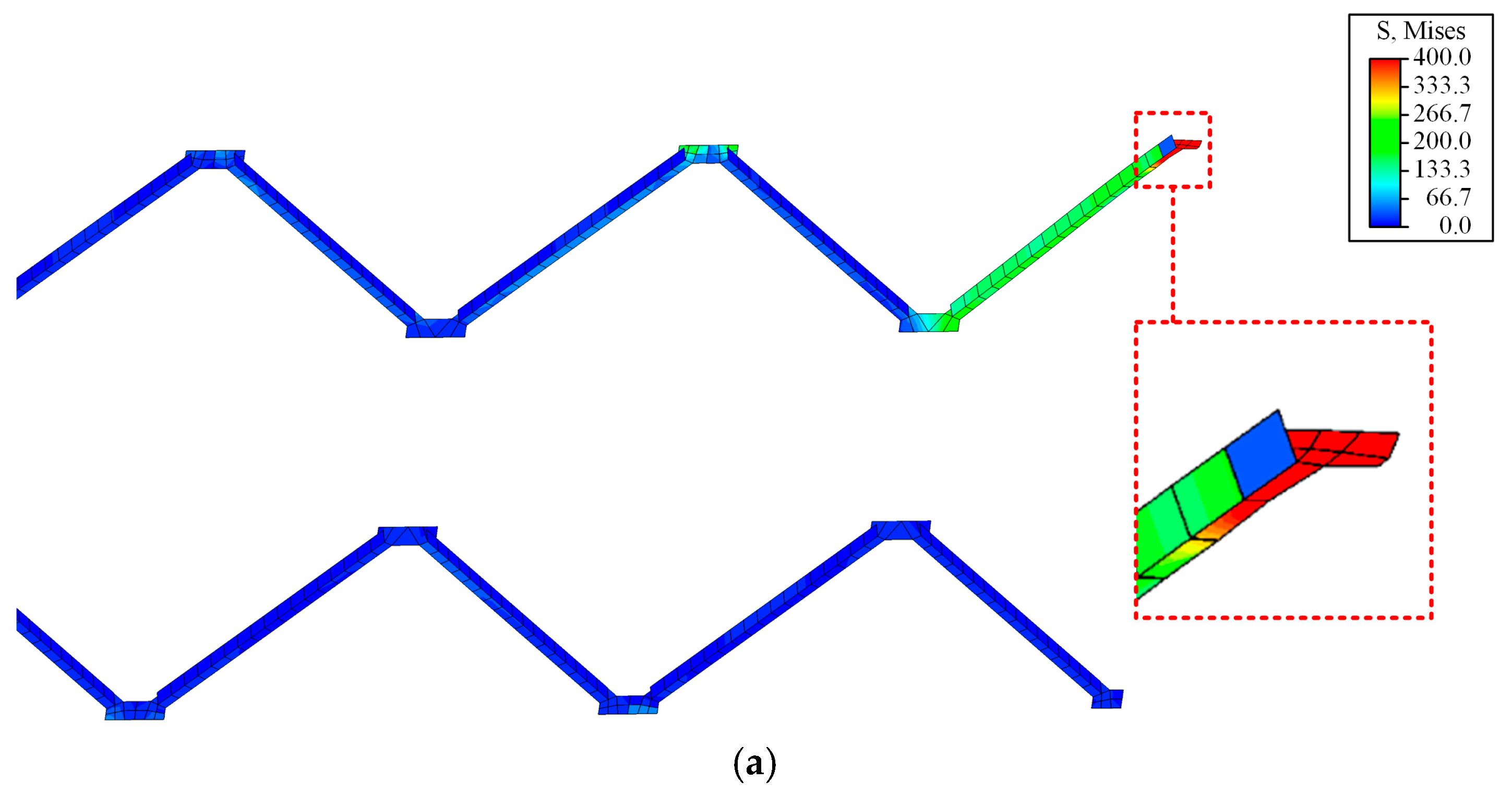
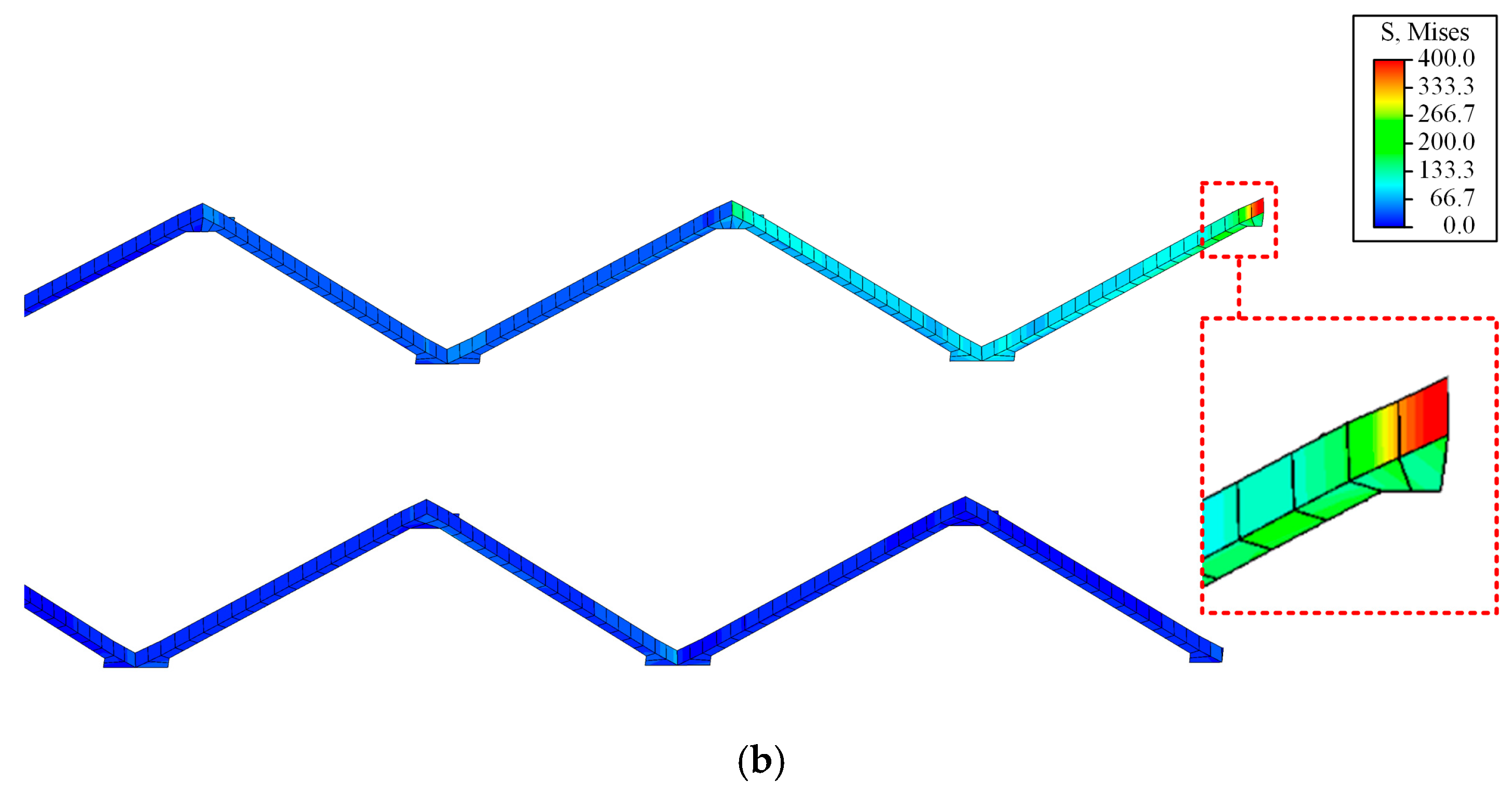
3.4. Failure of the Lower Lateral Bracing

The different design details of the lower lateral bracing have a significant impact on its lateral seismic response, and the key is the connection between the lower lateral bracing and the steel beam. As shown in Figure 17, the lower lateral bracing with the two connection designs exhibits two failure modes, vertical failure and connection failure, respectively, under lateral pounding. In Figure 17a, the stiffener of the lower lateral bracing is not interrupted and is tightly connected to the gusset plate on the steel beam. In Figure 17b, the lower lateral bracing connecting part of the gusset plate and the stiffener is too short and interrupted. Under the transverse load, the lower lateral bracing with continuous vertical stiffness will have bending deformation, and the failure mode is a vertical failure. The lower lateral bracing with discontinuous vertical stiffness will bend and deform in the area of sudden stiffness change, and the failure mode is a connection failure. It should be emphasized that under the action of earthquakes, it is difficult and unnecessary to ensure that the lower lateral bracing never fails. Under strong seismic action, the pounding force of the beam may be large, and significant deformation will occur at the bottom. In this case, repeated plastic bending deformations and energy dissipation in the lower lateral bracing and its stiffener are necessary. However, once the connection fails, lower lateral bracing cannot transmit and share the lateral pounding force of the steel beam, and there is a risk of breaking at the joint. Therefore, the lower lateral bracing is allowed to fail in an earthquake, but the reliability of the joint must be guaranteed.
Figure 18 shows the stress cloud of two lower lateral bracings. It can be seen that the lower lateral bracing with uneven vertical stiffness will cause stress concentration at the connection, and obvious bending deformation will occur at the gusset plate. The lower lateral bracing with uniform vertical stiffness only has a large area of stress at the stiffener and no significant deformation concentration.
In order to explore the response of lower lateral bracing with a truncated stiffener after connection failure, the vertical displacement and stress time history are further plotted as shown in Figure 19. The reference point of vertical displacement is the bending vertex of the lower lateral bracing, and the reference point of the stress is the connection point of the lower lateral bracing and the steel beam. It can be seen that when the pounding occurs, the stress peak occurs at the connection between the bracing and the steel beam, and the bracing has an upward vertical displacement. Comparison with Figure 16 shows that the vertical displacement of lower lateral bracing with a truncated stiffener (76 mm) is much higher than the vertical displacement of lower lateral bracing with a continuous stiffener (2 mm). Such a large vertical displacement of the lower lateral bracing with a truncated stiffener indicates that it has broken and failed the node, and the excessive deformation is concentrated in a small area. The lateral pounding causes a bend in the joint, which leads to the failure of the lower lateral bracing. Comparing the vertical displacement of the two bracings can further explain that the lower lateral bracing with the truncated stiffener will undergo excessive displacement and complete destruction, while the lower lateral bracing with the continuous stiffener undergoes only a limited displacement, continues to provide support, and repeatedly enters the plastic phase to dissipate energy. From the stress results of the connection points, it can also be seen that the peak and residual stresses (506 MPa and 287 MPa) of the lower lateral bracing with the truncated stiffener are higher than the peak and residual stresses (373 MPa and 180 MPa) of the lower lateral bracing with the continuous stiffener. This shows that once the connection fails, the lower lateral bracing will lose the lateral support effect on the steel beam.

4. Discussion

The numerical simulation results show that for slab-on-girder steel bridges, lower lateral bracing has a good seismic pounding damage control effect. From the perspective of steel beam deformation, the lower lateral bracing increases the lateral stiffness of the steel beam, thereby reducing the lateral deformation of the steel beam by about half at the location of the pounding (Figure 11). From the perspective of impact action, the lower lateral bracing shares about 1/3 of the impact force (Figure 12), thereby effectively reducing the pounding stress of the steel beam. Therefore, the lower lateral bracing reduces the pounding damage to the steel beam. Although severe buckling damage can occur in the lower lateral bracing under seismic action, it must be noted that the lower lateral bracing acts as a “fuse” in terms of seismic damage to steel beam webs. This “fuse” function is reflected in the fact that the bracing and the steel beam jointly bear the pounding effect, which protects the steel beam from serious local impact damage under the action of a transverse earthquake. When a large pounding occurs, the bracing fails before the steel beam and shows bending failure, which can consume energy in this process, reflecting the seismic design idea of multi-fortification.
It can be confirmed that it is very inappropriate to ignore the role of the lower lateral bracing when analyzing seismic damage to steel bridges, especially in relation to seismic pounding damage. In previous studies [16,17], the lower lateral bracing was also considered in the simulations, albeit simplified to ancillary components. Simplification of the bracing is generally considered only as beam elements in the finite element model, rather than refined plate elements. It is difficult to reasonably reflect the cross-sectional form and connection details of the lower lateral bracing in the beam element model, and the damage state and failure mode cannot be obtained. In fact, the interaction between the bracing and the steel beam is complex in the case of seismic pounding, and it is necessary to adopt a refined model with plate elements to consider the seismic damage to the beam and the bracing. In order to clarify the importance of lower lateral bracing in the seismic analysis of steel bridges, the results of this paper are further explained from the perspective of previous studies.
Aye et al. [16] discussed the damage survey of the Tawarayama Bridge affected by the 2016 Kumamoto earthquake. Tawarayama Bridge is a typical slab-on-girder steel bridge in which the lower lateral bracing was severely damaged by the earthquake. The authors used the B31 beam element to build the entire finite element model, including the steel beam and all lateral bracings. Under the design earthquake, 4% of the lateral bracings exceed the σ/σy value of 1. The lower lateral bracing has the maximum σ/σy. In addition, there is no lateral bracing buckling under one-way seismic actions, while the lateral bracing at the piers has a clear buckling tendency under two-way seismic actions.
Overall, the above views are consistent with the results of Section 3. However, the finite element model is composed entirely of beam elements, which means that the lateral bracing and steel beams are directly connected by two beams. Since the cross-sectional area and stiffness of the steel beam are much larger than the lateral bracing, the simulation results of the beam element can only indicate that the lateral bracing has been damaged under seismic action. This result may create a potential misconception that steel beams do not suffer seismic damage and that the lateral bracing should be removed to avoid seismic failure. In fact, according to the results of Figure 11, the importance of the lower lateral bracing is self-evident. Through refined numerical simulation, it can be found that, especially under the action of seismic pounding, the lower lateral bracing shares 1/3 of the pounding force of the steel beam (as shown in Figure 12). The lower lateral bracing disperses the huge pounding force from the key area to multiple areas on the beam, thereby significantly reducing the seismic damage to the steel beam. In general, fine numerical models must be used to reflect the seismic damage to steel beams, and lower lateral bracing has made significant contributions to controlling seismic pounding damage to steel beams. Of course, in addition to the lower lateral bracing, other factors may also help control seismic pounding damage to steel beams, such as setting dampers and limit devices. Taking into account the cost and complexity of construction, setting sufficient lower lateral bracings, and ensuring good connection details is an effective measure in current practice.
Mustafa and Miki [17] established a detailed three-dimensional finite element model of a viaduct steel girder bridge, including the steel beam of the plate element and the lower lateral bracing of the beam element. Through numerical simulation, it was found that the bottom plate of the end steel beam will rotate inward under seismic action, and damage will occur at the connection with lower lateral bracing. The lower lateral bracing showed a residual inelastic strain after an earthquake, and the maximum strain could be reduced by increasing the strength of the side block. The above conclusion fully shows that the steel beam will be damaged under the action of earthquakes, and the lower lateral bracing shares the damage to the steel beam. Although the study focused on the pounding damage of steel beams under earthquakes, it did not carefully consider the lower lateral bracing. Through the results of Figure 17 and Figure 18, it can be found that the connection details of the bracing and steel beam significantly affect the seismic performance of the lower lateral bracing. The lower lateral bracing has continuous stiffeners, which should be emphasized in the design.
In summary, the main advantage of this study is that the seismic damage of the slab-on-girder steel bridge is studied using a fine three-dimensional finite element model. All steel components are simulated using plate elements, and the material and geometric nonlinearity as well as the contact nonlinearity in the event of seismic poundings are taken into account. Through the simulation results, the seismic pounding damage to the steel beam, the lower lateral bracing, and the protective effect of the bracing on the steel beam are discussed. In addition, the failure mode of the lower lateral bracing and the influence on its seismic performance are further analyzed.

5. Conclusions

In this paper, a multiscale fine numerical simulation of continuous slab-on-girder steel bridges with and without lower lateral bracing is carried out to discuss their response and damage under seismic action. El Centro seismic recordings were selected and the peak acceleration amplitude was adjusted to 0.4 g as the input acceleration boundary condition for the finite element model. Focusing on the lateral seismic response of bridges, the following conclusions can be drawn:
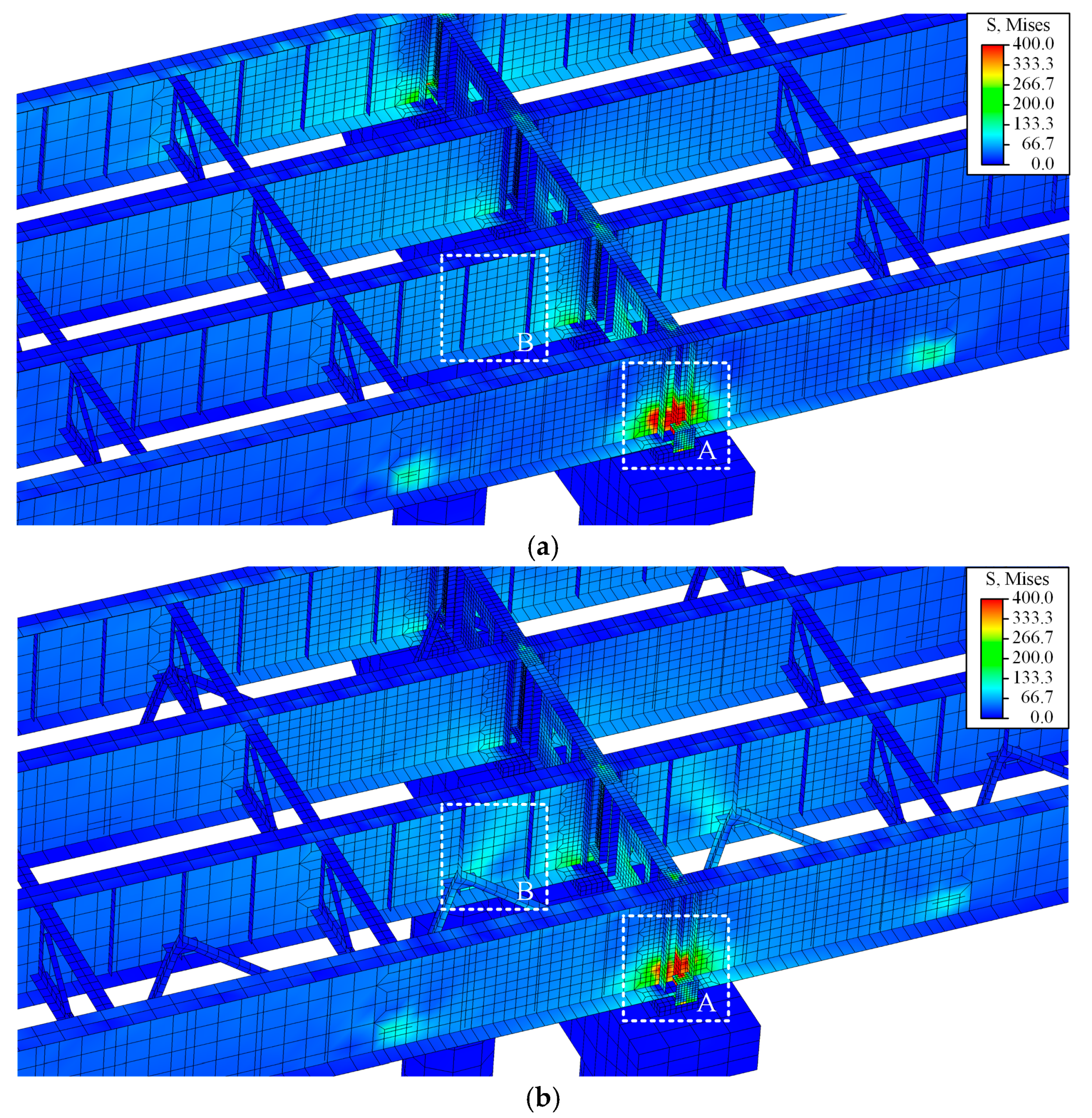
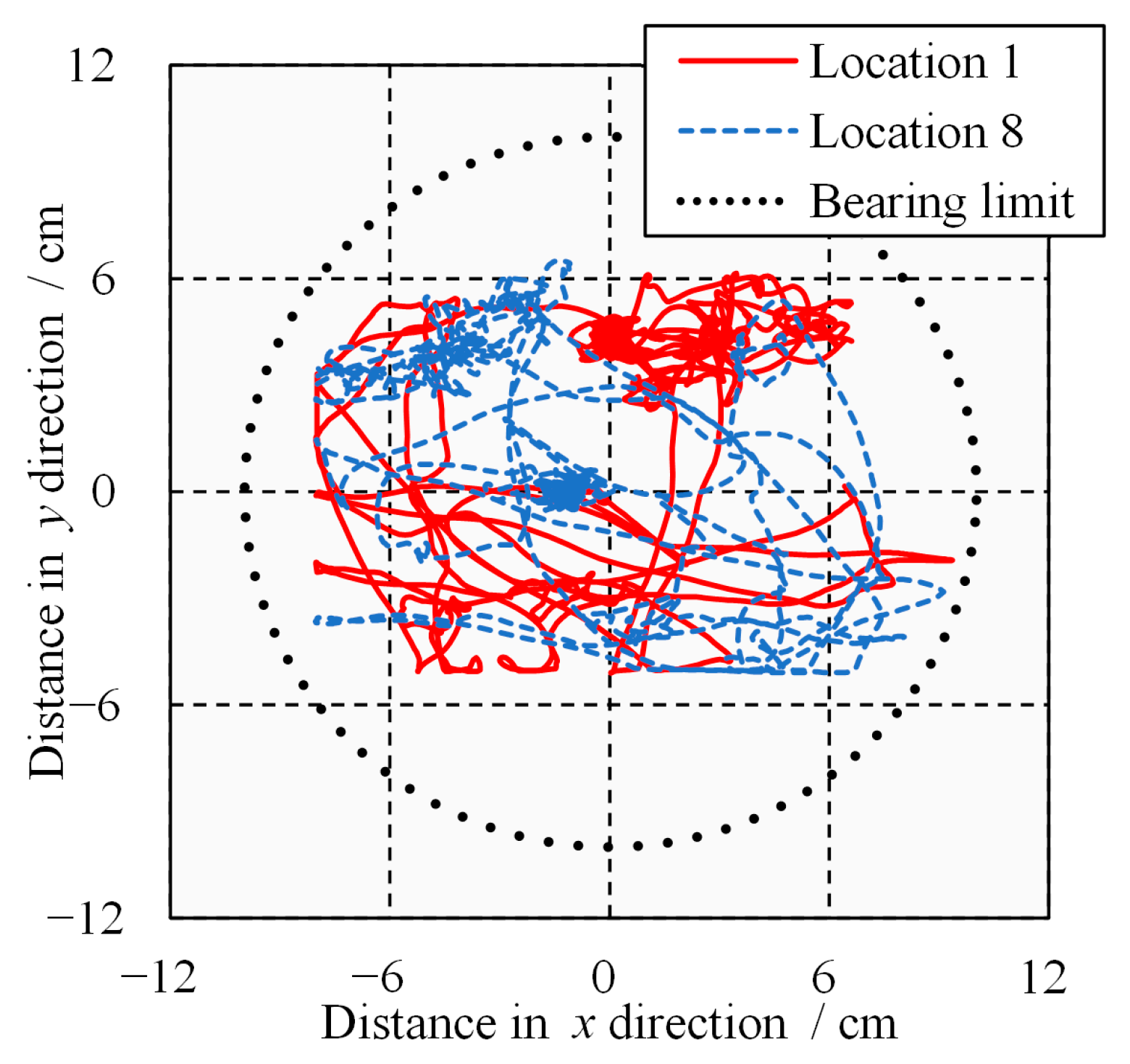
  • Under transverse seismic actions, the steel beams on both sides will experience seismic pounding and be damaged. For steel bridges with lower lateral bracing, the lateral collision damage of the steel beam is significantly reduced due to the sharing and transmission of the pounding force by the lower lateral bracing. The lower lateral bracing can share about 1/3 of the pounding action and reduce the displacement angle of the steel beam by 40%.
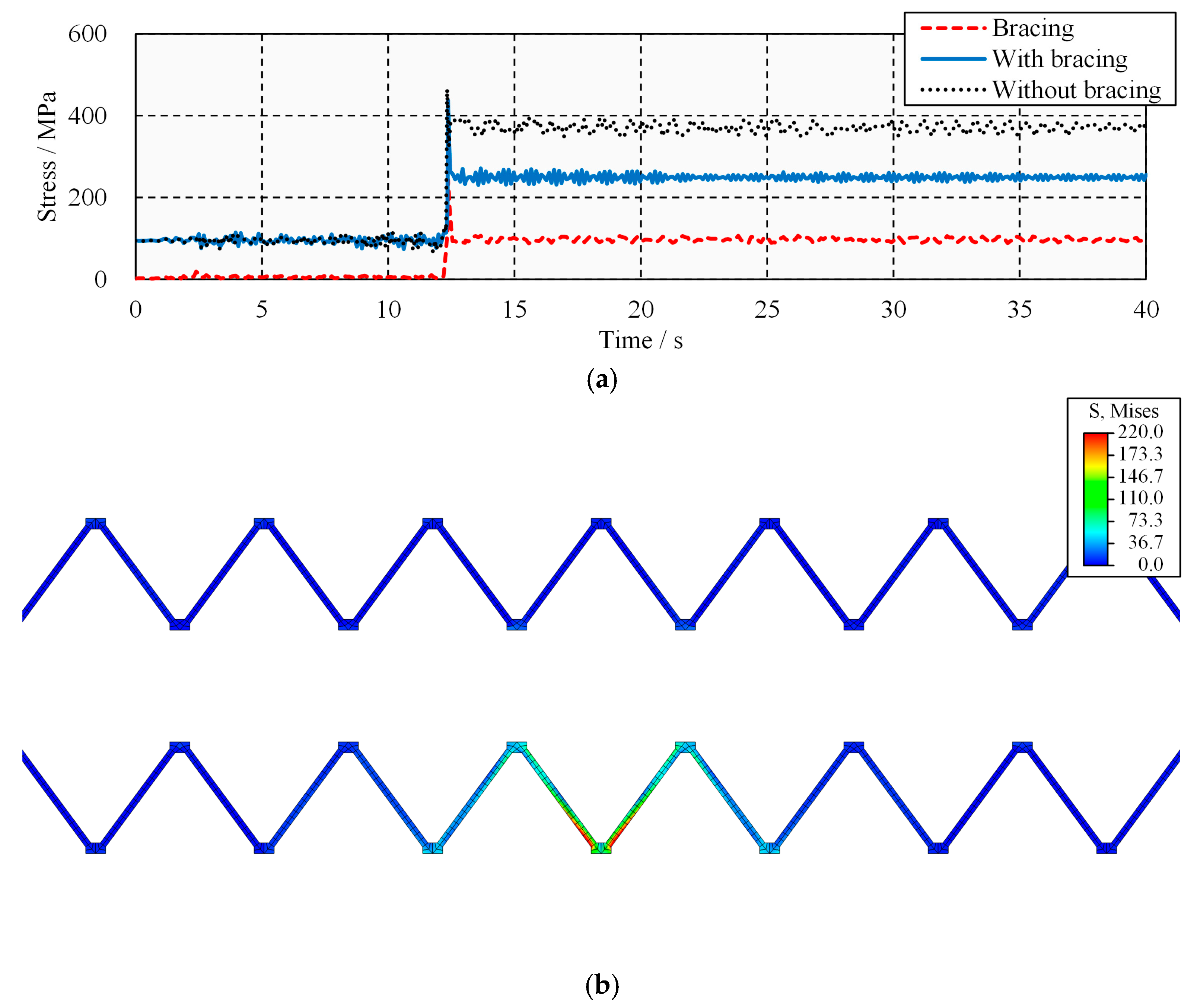
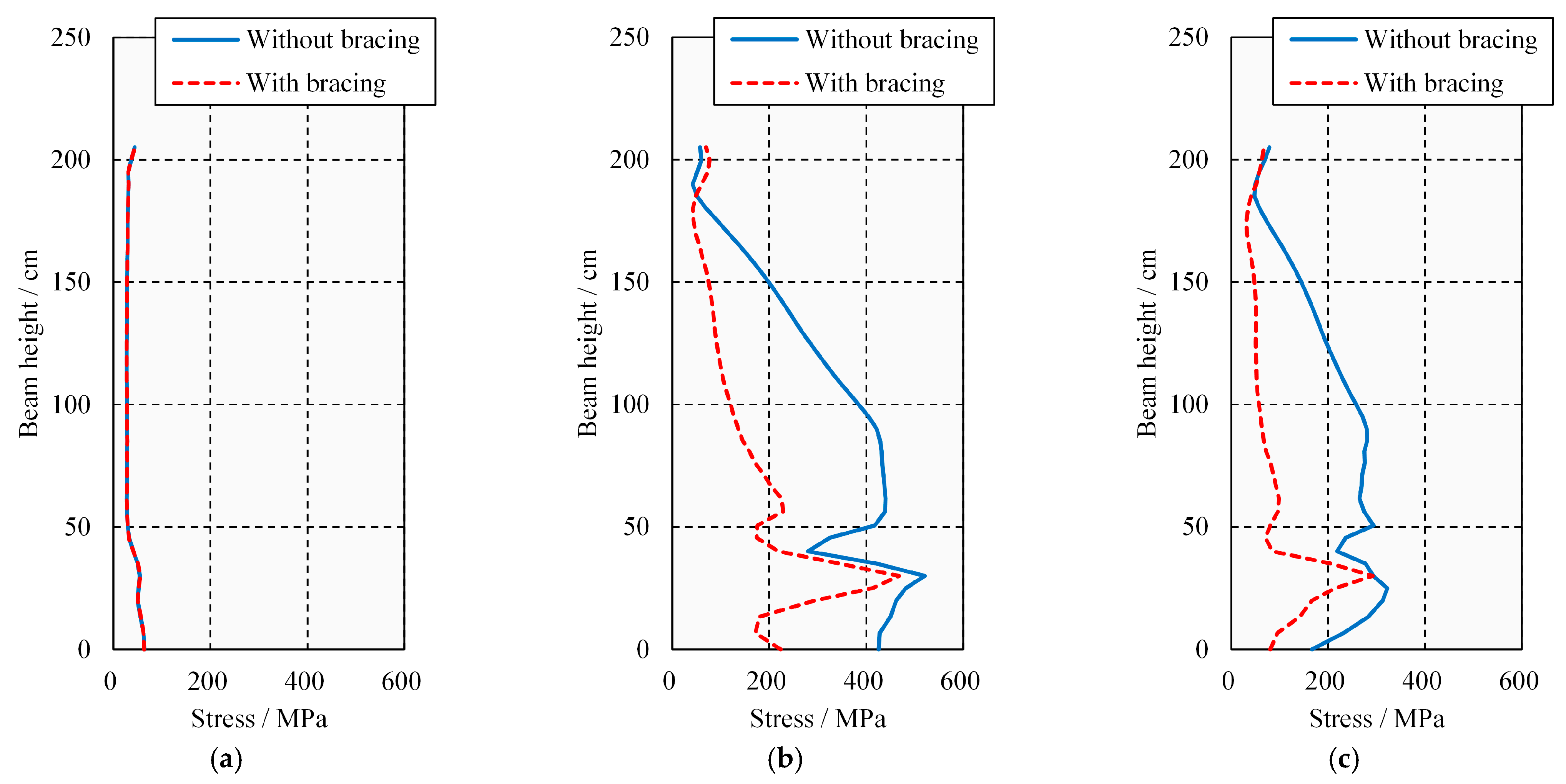
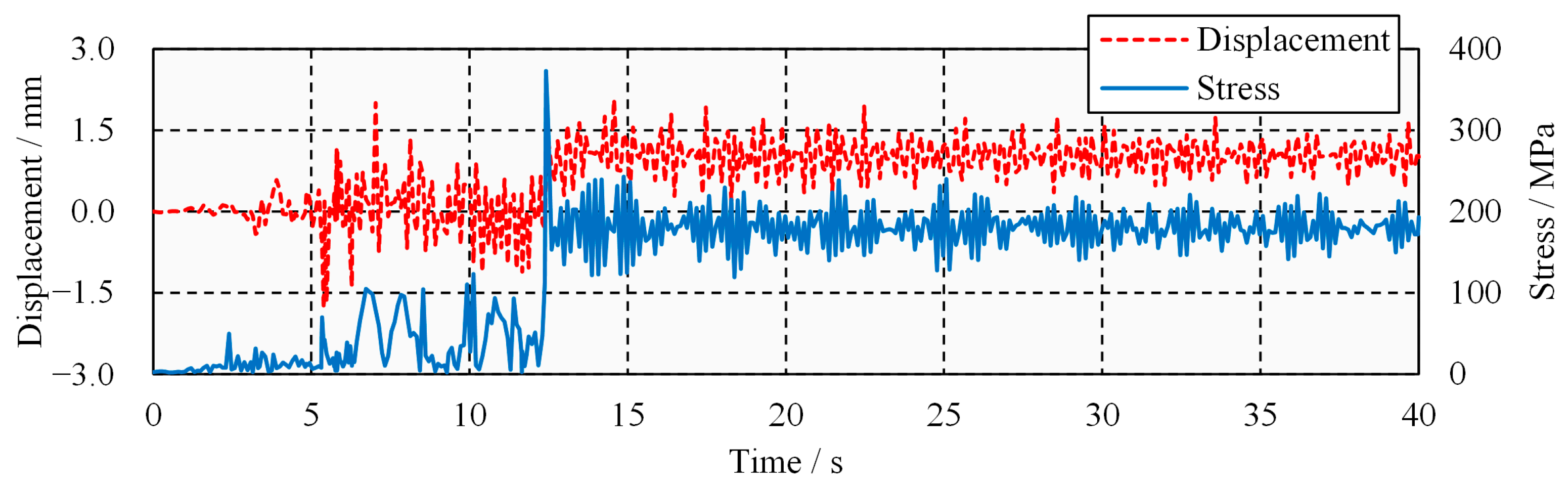
  • Under horizontal two-way seismic actions, the seismic response and damage of the steel beams on both sides are significantly amplified. Although the lower lateral bracing only slightly reduces the stress at the key, it significantly reduces the stress on other parts of the steel beam. The lower lateral bracing only elastically bends vertically under the full action of the earthquake.
  • The lower lateral bracing connection with discontinuous vertical stiffness will bend and deform in the area of sudden stiffness; that is, connection failure will occur. After the connection fails, the lower lateral bracing will lose the lateral support effect on the steel beam.
The novelty of this paper is paying attention to the previously neglected lower lateral bracing structure and confirming that it plays an important role in controlling the seismic pounding damage to steel beams. Although this phenomenon has been hinted at by the actual seismic damage to steel bridges, few studies have been refined to analyze it. The possible failure modes and engineering design recommendations for the lower lateral bracing are further proposed in this paper.
In summary, lower lateral bracing should be considered in the design of slab-on-girder steel bridges. It significantly improves the lateral seismic performance of the bridge and reduces the seismic pounding damage to steel beams. In addition, attention must be paid to the design of the connection between the lower lateral bracing and the steel beam to avoid connection failure.
On the basis of this research study, the research on the seismic pounding problem of steel bridges can be further improved from the perspective of an analysis model and algorithm development. In terms of analytical models, many existing beam dynamics analysis models focus on the beams’ dynamic vibration characteristics [24,25,26,27]. The research content of this paper is based on the three-dimensional finite element analysis of an entire bridge and its components. In fact, it is also necessary to propose a theoretical analysis model of steel girder bridges that can consider the seismic pounding effect from the perspective of simplifying the model and improving its practicality. The seismic response of steel girder bridges can be obtained accurately without using complex finite element models. In terms of algorithm development, deep learning and artificial intelligence have a significant impact on bridge and structural engineering and are widely used in the field of numerical modeling and prediction [28,29,30]. Therefore, in future work, the method of deep learning can be considered to assist in the decision-making of the form and quantity of the lower lateral bracings so as to avoid a large number of numerical model optimization work.

Author Contributions

Data curation, F.S.; funding acquisition, D.W.; investigation, J.D.; methodology, F.S.; project administration, D.W.; resources, J.D.; validation, L.T.; visualization, L.T.; writing—original draft, F.S.; writing—review and editing, D.W. All authors have read and agreed to the published version of the manuscript.

Funding

This research was funded by the National Natural Science Foundation of China, grant number 52178473.

Institutional Review Board Statement

Not applicable.

Informed Consent Statement

Not applicable.

Data Availability Statement

Data are contained within the article.

Conflicts of Interest

The authors declare no conflict of interest.

References

  1. Kharazian, A.; López-Almansa, F. State-of-the-Art of Research on Seismic Pounding between Buildings with Aligned Slabs. Arch. Comput. Methods Eng. 2017, 26, 327–345. [Google Scholar] [CrossRef]
  2. Miari, M.; Choong, K.K.; Jankowski, R. Seismic Pounding between Bridge Segments: A State-of-the-Art Review. Arch. Comput. Methods Eng. 2020, 28, 495–504. [Google Scholar] [CrossRef]
  3. Association, J.B. Kumamoto Earthquake Bridge Damage Survey Report; Asian Disaster Reduction Center (ADRC): Kobe, Japan, 2016. [Google Scholar]
  4. Bi, K.M.; Hao, H.; Chouw, N. Influence of ground motion spatial variation, site condition and SSI on the required separation distances of bridge structures to avoid seismic pounding. Earthq. Eng. Struct. Dyn. 2011, 40, 1027–1043. [Google Scholar] [CrossRef]
  5. Jankowski, R. Pounding between Superstructure Segments in Multi-Supported Elevated Bridge with Three-Span Continuous Deck Under 3D Non-Uniform Earthquake Excitation. J. Earthq. Tsunami 2015, 9, 1550012. [Google Scholar] [CrossRef]
  6. Li, N.N.; Xu, W.B.; Chen, Y.J.; Yan, W.M. Experimental research on adjacent pounding effect of midspan curved bridge with longitudinal slope. Eng. Struct. 2019, 196, 109320. [Google Scholar] [CrossRef]
  7. Bi, K.M.; Hao, H. Modelling of shear keys in bridge structures under seismic loads. Soil Dyn. Earthq. Eng. 2015, 74, 56–68. [Google Scholar] [CrossRef]
  8. Yang, M.G.; Meng, D.L.; Gao, Q.; Zhu, Y.P.; Hu, S.T. Experimental study on transverse pounding reduction of a high-speed railway simply-supported girder bridge using rubber bumpers subjected to earthquake excitations. Eng. Struct. 2019, 196, 109290. [Google Scholar] [CrossRef]
  9. Xu, L.Q.; Fu, P.Y.; Spencer, B.F. Maintaining bridge alignment during seismic events: Shear key design and implementation guidelines. J. Bridge Eng. 2020, 25, 04020017. [Google Scholar] [CrossRef]
  10. Meng, D.; Yang, M.; Yang, Z.; Chouw, N. Effect of earthquake-induced transverse poundings on a 32 m span railway bridge isolated by friction pendulum bearings. Eng. Struct. 2022, 251, 113538. [Google Scholar] [CrossRef]
  11. Jankowski, R.; Wilde, K.; Fujino, Y. Reduction of pounding effects in elevated bridges during earthquakes. Earthq. Eng. Struct. Dyn. 2000, 29, 195–212. [Google Scholar] [CrossRef]
  12. Guo, A.X.; Li, Z.J.; Li, H.; Ou, J.P. Experimental and analytical study on pounding reduction of base-isolated highway bridges using MR dampers. Earthq. Eng. Struct. Dyn. 2009, 38, 1307–1333. [Google Scholar] [CrossRef]
  13. Shrestha, B.; Hao, H.; Ibrahim, N.H.J.; Bi, K.M. On the effectiveness of rotational friction hinge damper to control responses of multi-span simply supported bridge to non-uniform ground motions. Adv. Struct. Eng. 2016, 19, 1575–1591. [Google Scholar] [CrossRef]
  14. Won, J.H.; Mha, H.S.; Kim, S.H. Effects of the earthquake-induced pounding upon pier motions in the multi-span simply supported steel girder bridge. Eng. Struct. 2015, 93, 1–12. [Google Scholar] [CrossRef]
  15. Zheng, Y.; Xiao, X.; Zhi, L.H.; Wang, G.B. Evaluation on impact interaction between abutment and steel girder subjected to nonuniform seismic excitation. Shock Vib. 2015, 2015, 981804. [Google Scholar] [CrossRef]
  16. Aye, M.N.; Kasai, A.; Shigeishi, M. An investigation of damage mechanism induced by earthquake in a plate girder bridge based on seismic response analysis: Case study of Tawarayama bridge under the 2016 Kumamoto earthquake. Adv. Civ. Eng. 2018, 2018, 9293623. [Google Scholar]
  17. Mustafa, S.; Miki, C. Design of rupture strength of side blocks in elevated steel girder bridges with elastomeric bearings. Int. J. Steel Struct. 2020, 20, 885–896. [Google Scholar] [CrossRef]
  18. Dassault, S. Abaqus 2016 Analysis User’s Guide; Dassault Systèmes: Paris, France, 2016. [Google Scholar]
  19. Tang, Z.Z.; Xie, X.; Wang, T.; Wang, J.Z. Study on FE models in elasto-plastic seismic performance evaluation of steel arch bridge. J. Constr. Steel Res. 2015, 113, 209–220. [Google Scholar] [CrossRef]
  20. Chaboche, J.L. A review of some plasticity and viscoplasticity constitutive theories. Int. J. Plast. 2008, 24, 1642–1693. [Google Scholar] [CrossRef]
  21. Shi, Y.J.; Wang, M.; Wang, Y.Q. Experimental study of structural steel constitutive relationship under cyclic loading. J. Build. Mater. 2012, 15, 293–300. (In Chinese) [Google Scholar]
  22. Xing, Y.; Xu, Y.N.; Guo, Q.; Jiao, J.F.; Chen, Q.W. Experimental study on friction performance of damaged interface in steel-concrete composite beam connected by high-strength bolt. Adv. Struct. Eng. 2021, 24, 334–345. [Google Scholar] [CrossRef]
  23. Baker, J.W. Quantitative classification of near-fault ground motions using wavelet analysis. Bull. Seismol. Soc. Am. 2007, 97, 1486–1501. [Google Scholar] [CrossRef]
  24. Ahmadi, M.; Nikkhoo, A. Utilization of characteristic polynomials in vibration analysis of non-uniform beams under a moving mass excitation. Appl. Math. Model. 2014, 38, 2130–2140. [Google Scholar] [CrossRef]
  25. Lei, T.; Zheng, Y.F.; Yu, R.J.; Yan, Y.K.; Xu, B. Dynamic Response of Slope Inertia-Based Timoshenko Beam under a Moving Load. Appl. Sci. 2022, 12, 3045. [Google Scholar] [CrossRef]
  26. Ouzizi, A.; Abdoun, F.; Azrar, L. Nonlinear dynamics of beams on nonlinear fractional viscoelastic foundation subjected to moving load with variable speed. J. Sound Vib. 2022, 523, 116730. [Google Scholar] [CrossRef]
  27. Shi, F.; Wang, D.S.; Cheng, L. Study of flexural vibration of variable cross-section box-girder bridges with corrugated steel webs. Structures 2021, 33, 1107–1118. [Google Scholar] [CrossRef]
  28. Tang, W.J.; Wang, D.S.; Huang, H.B.; Dai, J.C.; Shi, F. A pre-trained deep learning model for fast online prediction of structural seismic responses. Int. J. Struct. Stab. Dyn. 2023. [Google Scholar] [CrossRef]
  29. Hsiao, I.H.; Chung, C.Y. AI-infused semantic model to enrich and expand programming question generation. J. Artif. Intell. Technol. 2022, 2, 47–54. [Google Scholar] [CrossRef]
  30. Du, H.; Du, S.; Li, W. Probabilistic time series forecasting with deep non-linear state space models. CAAI Trans. Intell. Technol. 2023, 8, 3–13. [Google Scholar] [CrossRef]
Figure 1. Damages of slab-on-girder steel bridges in Kumamoto earthquake. (a) Steel beam damage; (b) lower lateral bracing buckling.
Applsci 13 12787 g001
Figure 2. View of the slab-on-girder steel bridge.
Applsci 13 12787 g002
Figure 3. Layout and dimensions of the bridge (unit: cm). (a) Layout of bridge; (b) cross-section of bridge; (c) side view of abutment; (d) cross-section of pier; (e) side view of pier.
Applsci 13 12787 g003
Figure 4. Deformation relationships of plate and beam elements. (a) Interface relationship; (b) under axial force; (c) under moment.
Applsci 13 12787 g004
Figure 5. Three-dimensional multiscale FE model of the bridge. (a) Global diagram; (b) top view; (c) detail enlargement (x direction); (d) detail enlargement (y direction); (e) detail enlargement of piers.
Applsci 13 12787 g005aApplsci 13 12787 g005b
Figure 6. Resilience model of bearing.
Applsci 13 12787 g006
Figure 7. Acceleration time history of El Centro Array #9.
Applsci 13 12787 g007
Figure 8. Numerical convergence analysis of the model.
Applsci 13 12787 g008
Figure 9. The first three-order vertical natural modes. (a) First-order mode shape; (b) second-order mode shape; (c) third-order mode shape.
Applsci 13 12787 g009
Figure 10. Stress cloud diagram of steel beam (unit: MPa). (a) Pounding of steel beams without lower lateral bracing; (b) pounding of steel beams with lower lateral bracing.
Applsci 13 12787 g010
Figure 11. Residual deformation of steel beams. (a) Schematic diagram of the pounding rotation of a steel beam; (b) the displacement angle of the steel beam.
Applsci 13 12787 g011
Figure 12. Stress of steel beam and lower lateral bracing. (a) Stress time history of steel beam and lower lateral bracing; (b) stress cloud of lower lateral bracing (unit: MPa).
Applsci 13 12787 g012
Figure 13. Relative displacement of the steel beam at the bearing.
Applsci 13 12787 g013
Figure 14. Stress cloud diagram of steel beam (unit: MPa). (a) Pounding of steel beams without lower lateral bracing; (b) pounding of steel beams with lower lateral bracing.
Applsci 13 12787 g014
Figure 15. Vertical stress distribution of steel webs. (a) Stress under self-weight; (b) peak stress on pounding; (c) residual stress after the earthquake.
Applsci 13 12787 g015
Figure 16. Vertical displacement and stress time history of the lower lateral bracing.
Applsci 13 12787 g016
Figure 17. Failure mode of lower lateral bracing. (a) Vertical failure; (b) connection failure.
Applsci 13 12787 g017
Figure 18. Stress cloud plot of lower lateral bracing (unit: MPa). (a) Lower lateral bracing with truncated stiffener; (b) lower lateral bracing with continuous stiffener.
Applsci 13 12787 g018aApplsci 13 12787 g018b
Figure 19. Vertical displacement and stress time history of the lower lateral bracing with truncated stiffener.
Applsci 13 12787 g019
Table 1. Material parameters of the Q345qE steel.
σ|0/MPaQ/MPabisoC1/MPaγ1C2/MPaγ2C3/MPaγ3C4/MPaγ4
429211.279931756773116285434145029
Table 2. Results of natural vibration characteristics.
NO.Frequency/HzError/%Mode Shape Description
TestFEM
12.912.803.81Vertical antisymmetric bending
23.663.462.51Vertical bending on side spans
34.764.645.43Vertical symmetrical bending
Disclaimer/Publisher’s Note: The statements, opinions and data contained in all publications are solely those of the individual author(s) and contributor(s) and not of MDPI and/or the editor(s). MDPI and/or the editor(s) disclaim responsibility for any injury to people or property resulting from any ideas, methods, instructions or products referred to in the content.

