
Study on Active Support Parameters for Surrounding Rock with Ultra-Large Span Open-Off Cut in Thick Coal Seam

Abstract
:1. Introduction
2. Stability Analysis of Ultra-Large Span Open-Off Cutting Areas
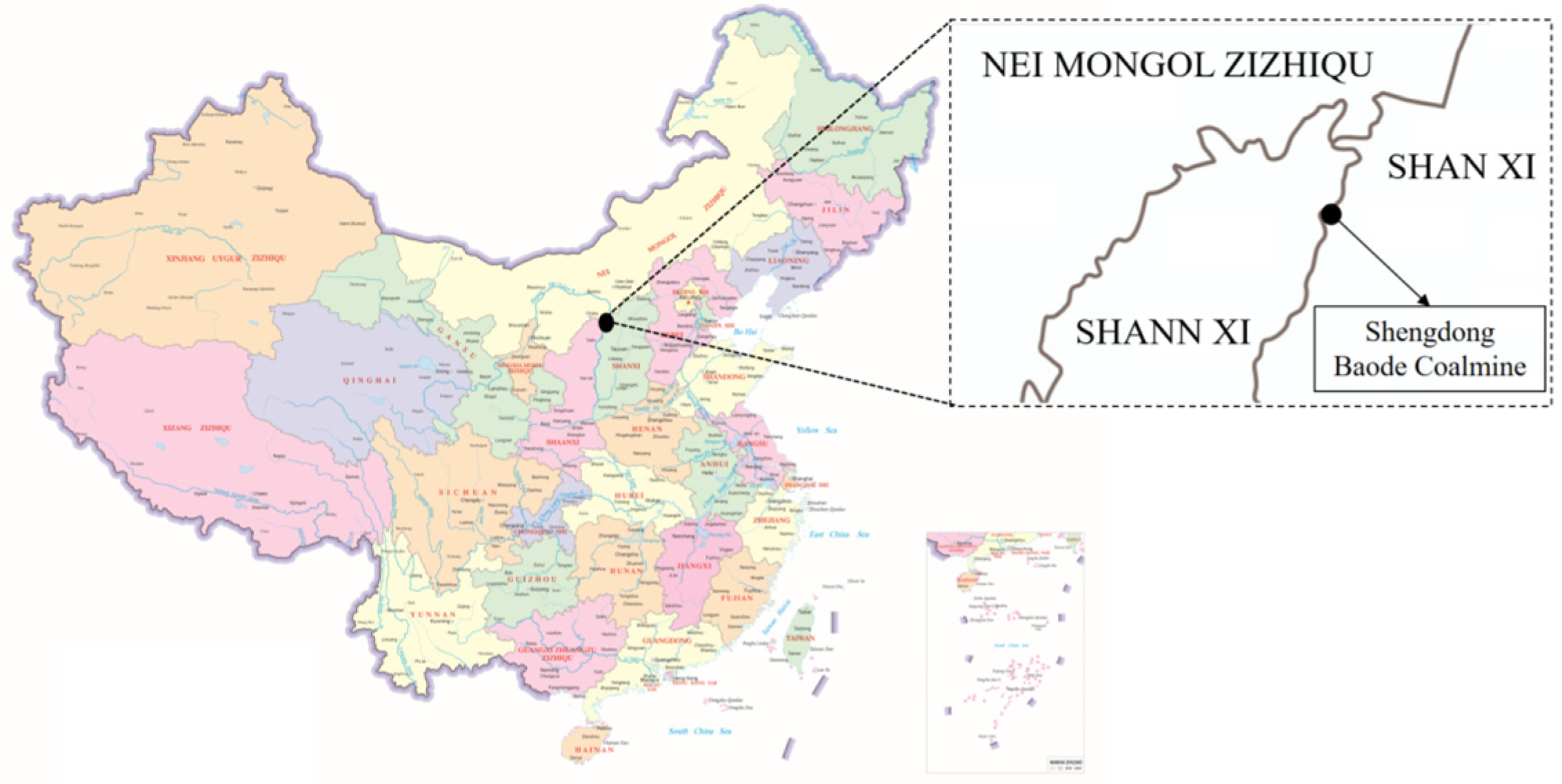
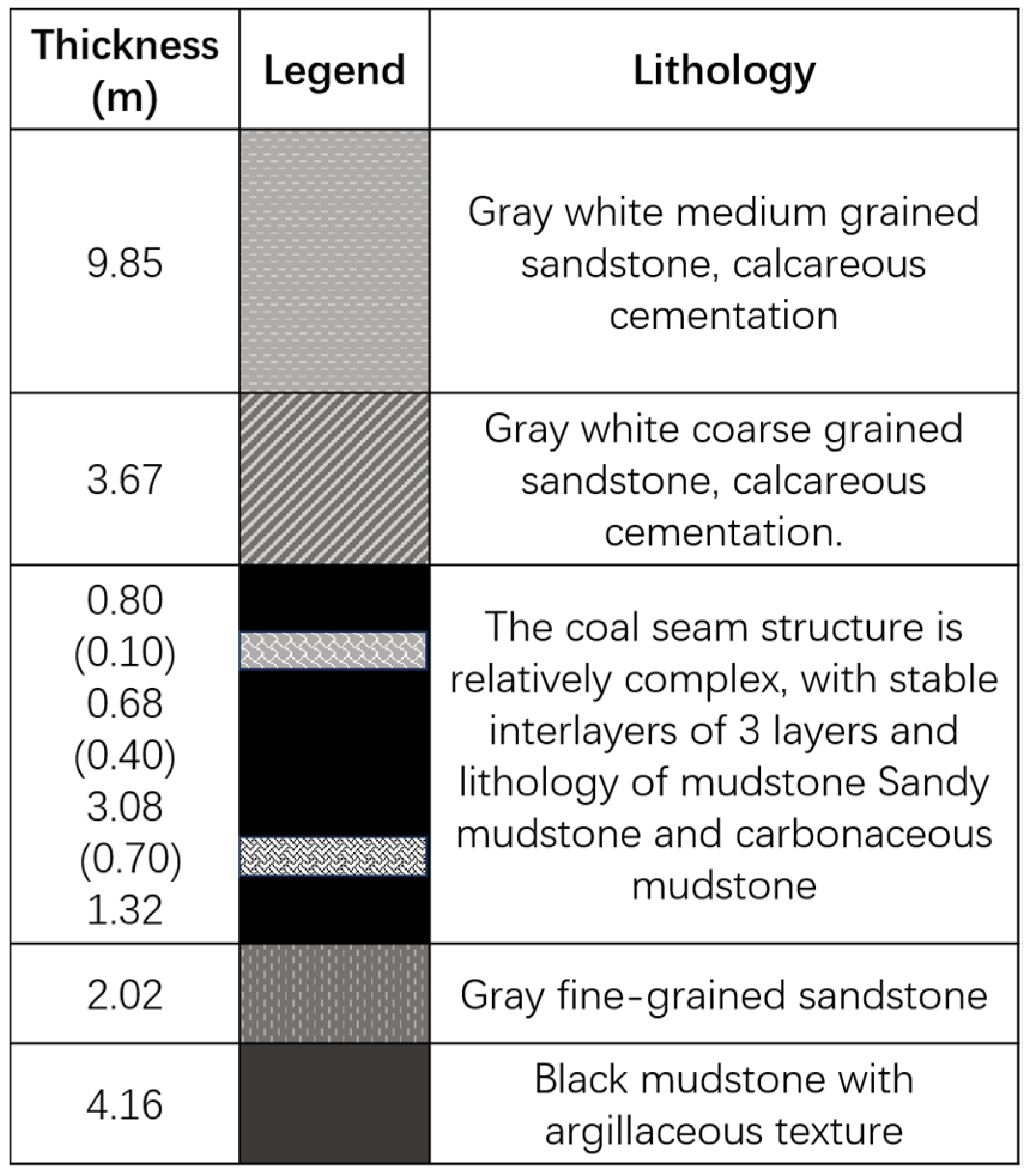
2.1. Engineering Background
2.2. Analysis of Factors Influencing Stability in the Open-Off Cutting Areas
2.3. Cutting Span and Stability of Working Face
- (1)
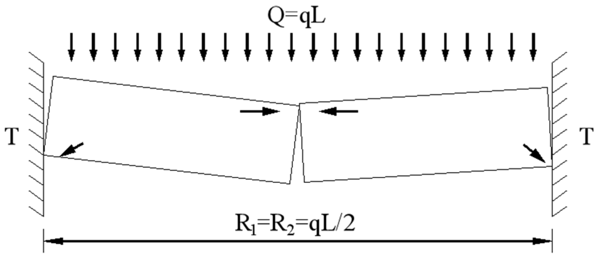
- Mechanical Model
- (2)
- Conditions for fracture instability
3. Design of Active Support Parameters for Surrounding Rock with Ultra-Large Span Open-Off Cut in Thick Coal Seam
3.1. Theoretical Analysis of Support Parameter Design
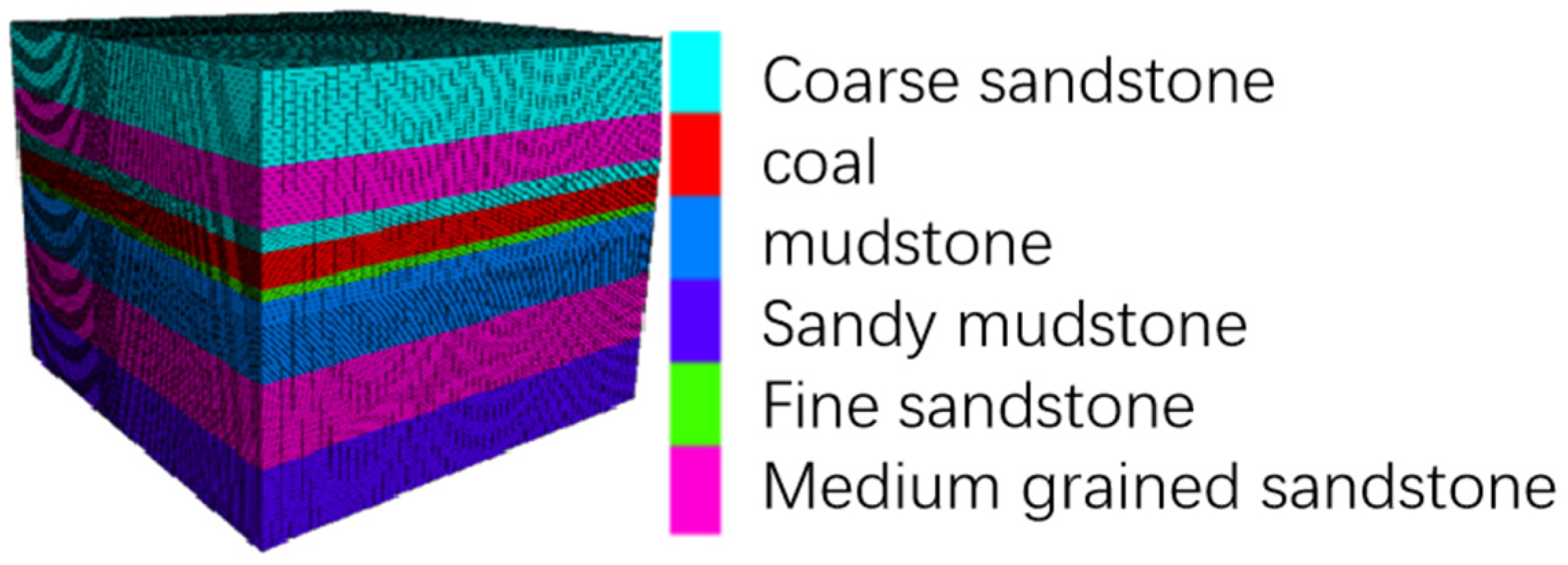
3.2. Numerical Model Establishment
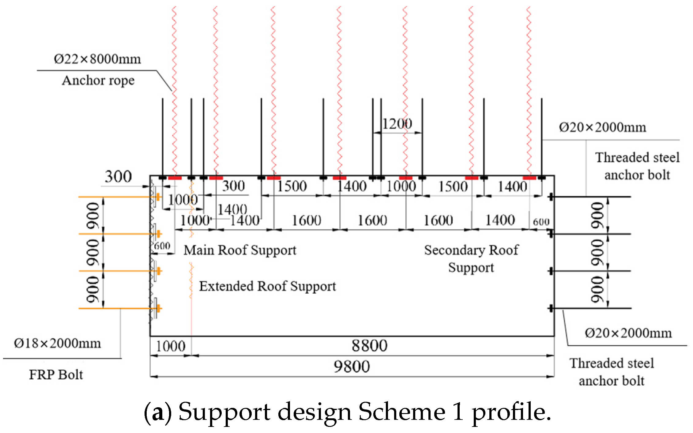
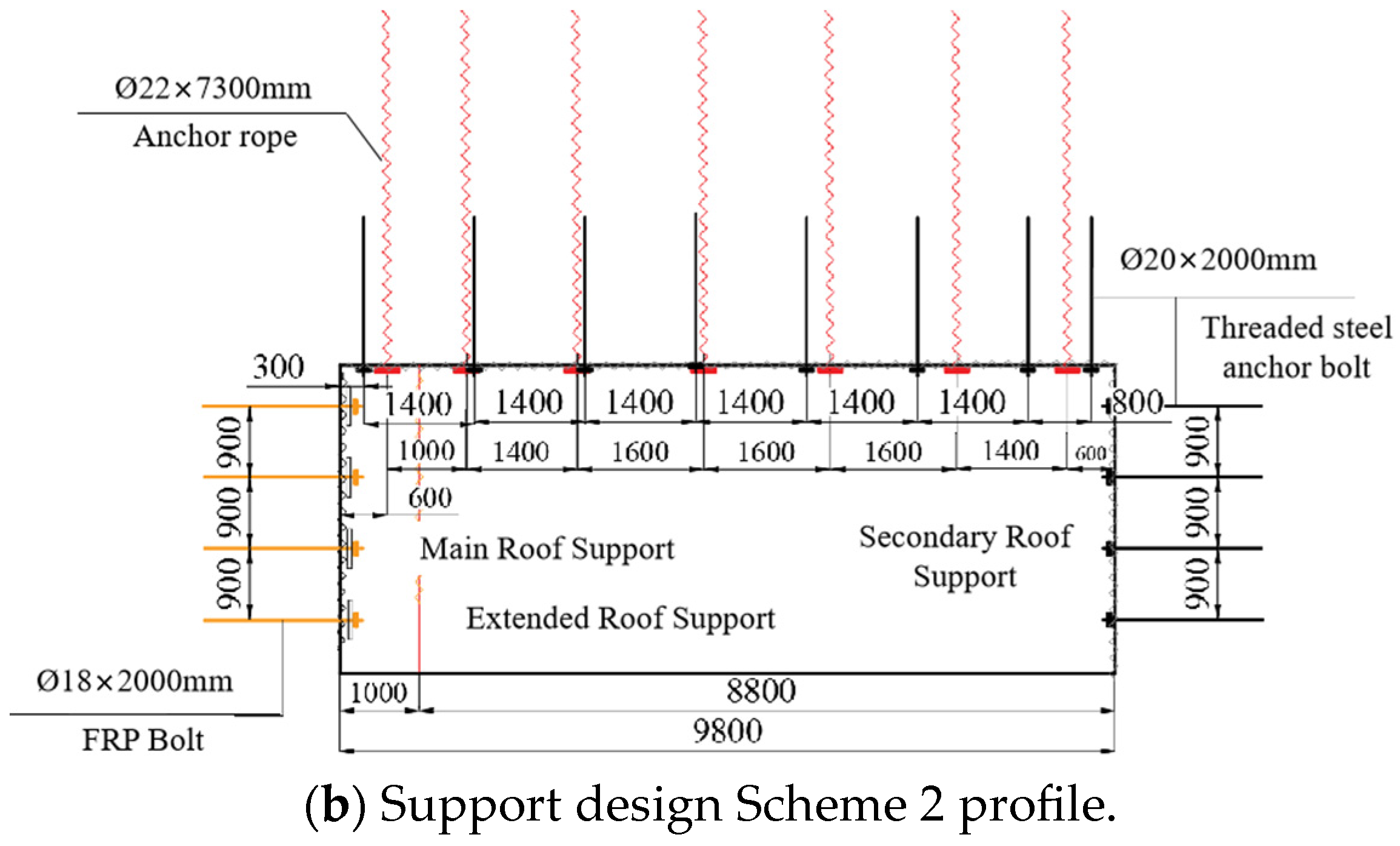
3.3. Numerical Analysis of Support Parameter Design
- (1)
- Displacement field analysis of surrounding rock
- (2)
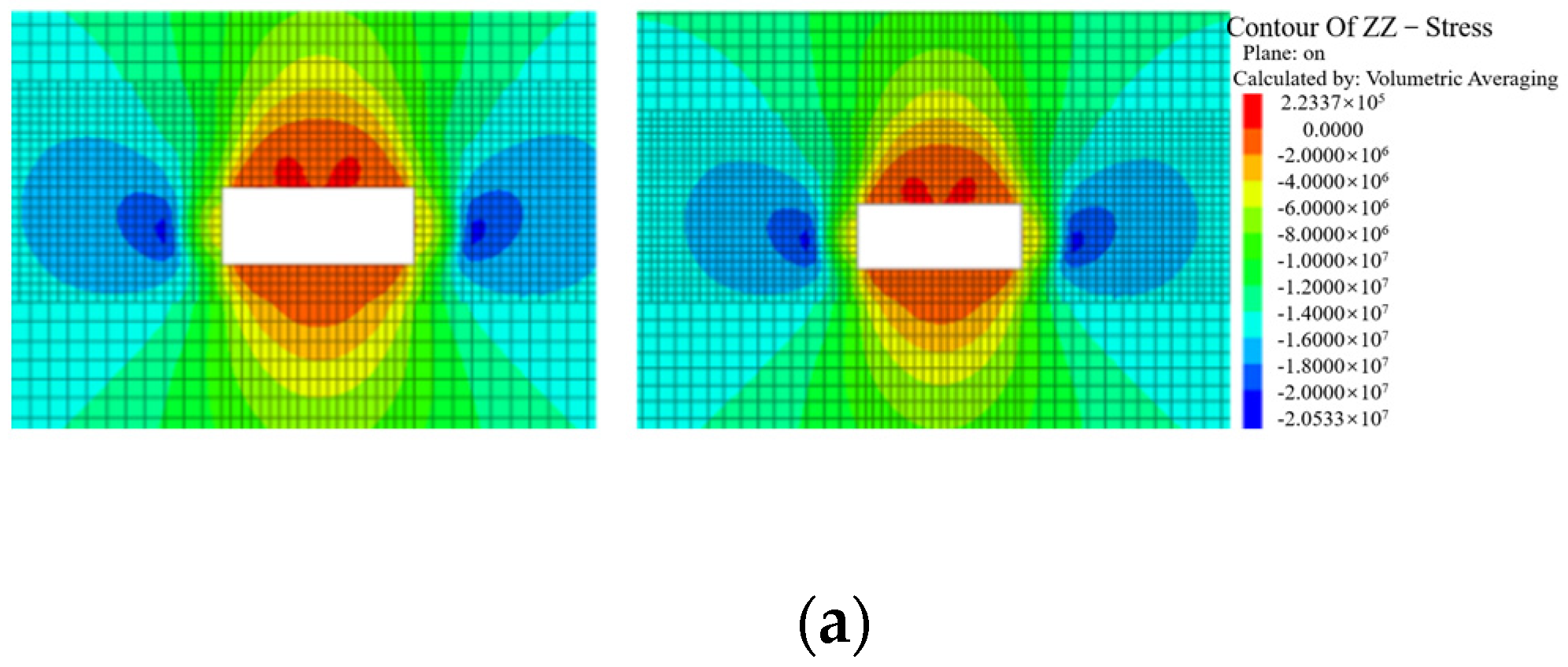
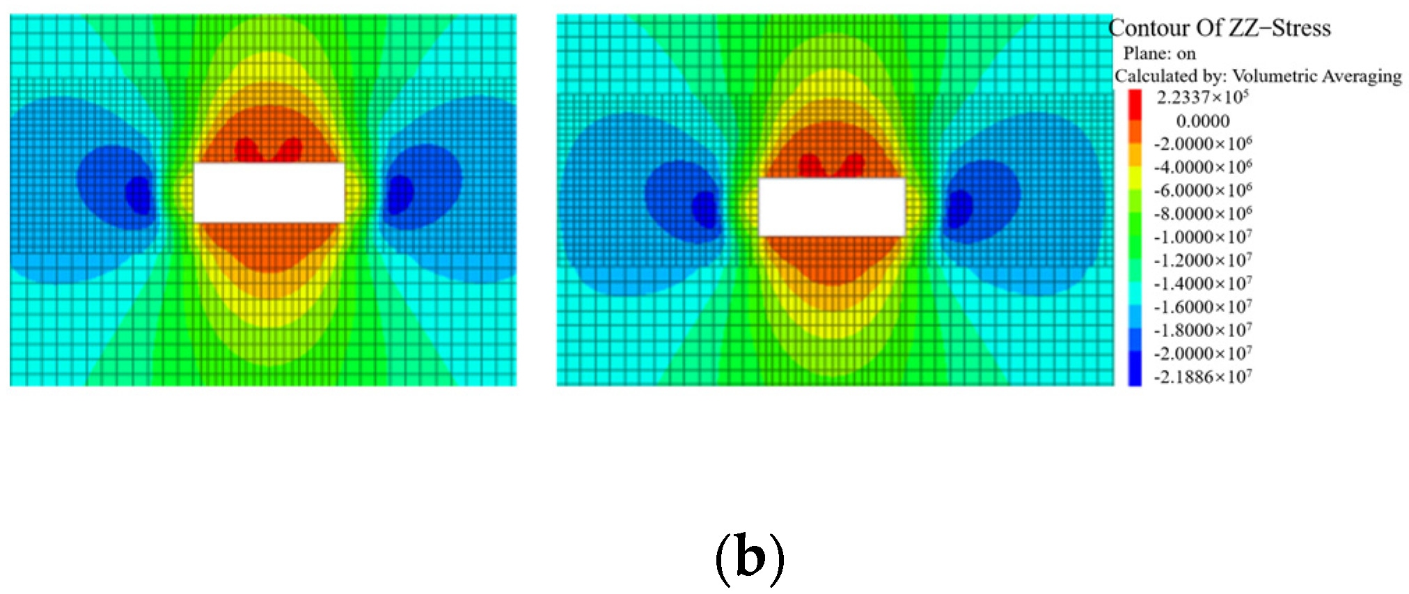
- Stress field analysis of surrounding rock
- (3)
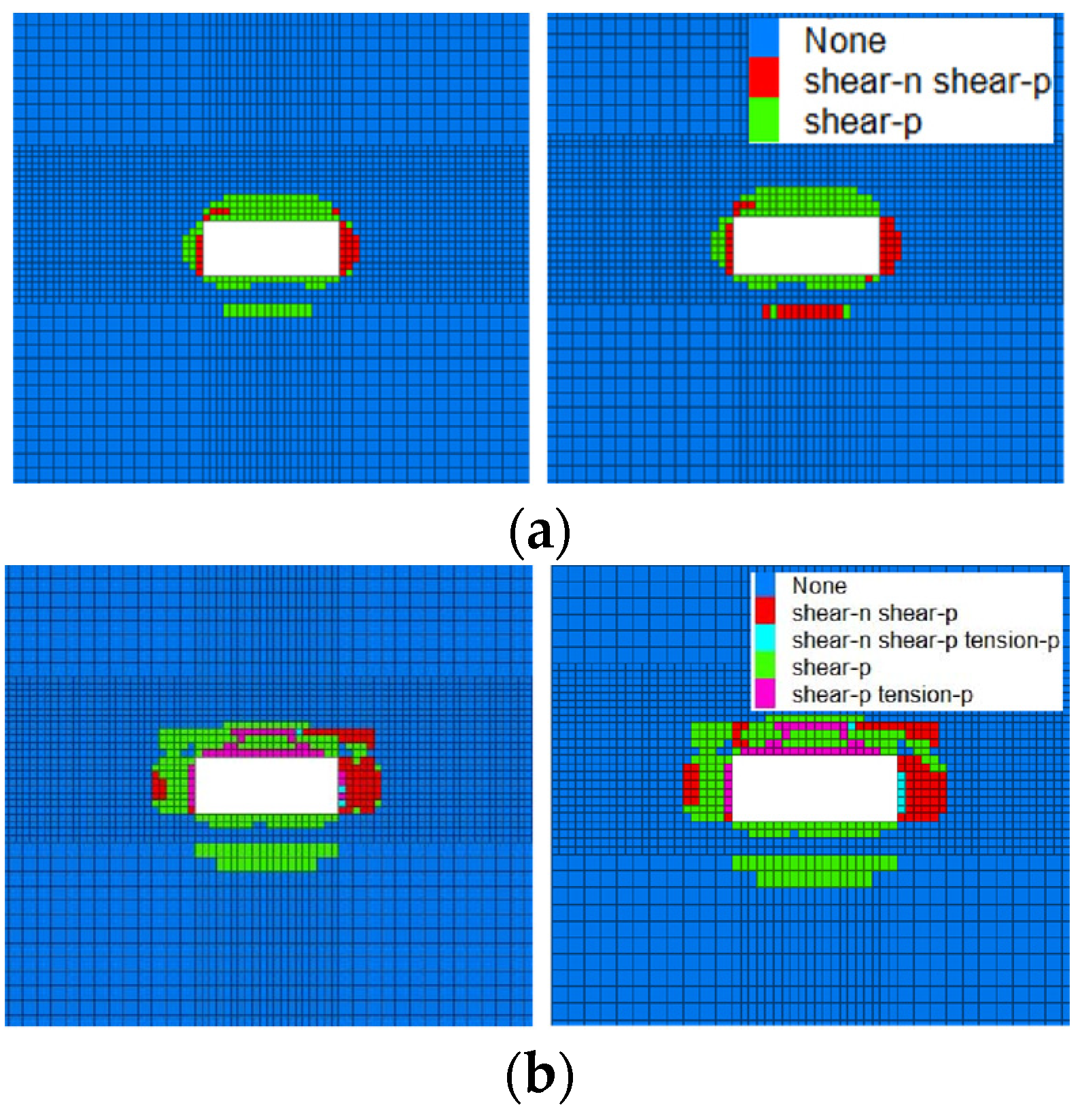
- Plastic zone analysis of surrounding rock
4. Field Application
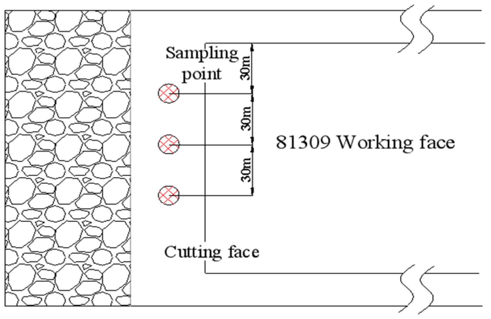
4.1. Test Site
4.2. Monitoring of Cutting Surrounding Rock Deformation
5. Conclusions
- (1)
- In order to effectively control the stability of the surrounding rock of the large-span cutting roadway, combined with the geological conditions of Baode Coal Mine, the optimal supporting scheme parameters are proposed by using theoretical analysis, numerical simulation, and field tests.
- (2)
- The ultra-large span of the open-off cutting in thick coal seams is the primary factor affecting the stability of the cutting. The span is inversely proportional to the stress borne by the cutting roof. The ratio of span to thickness is a key factor influencing the stability of the roof layer and the stability of rock beams.
- (3)
- Through comprehensive comparative analysis of changes in surrounding rock stress, displacement, and plastic zone through numerical simulation, Scheme 1 proved significantly superior to Scheme 2. Under Scheme 1, the approach amount of the roof, floor, and sides decreased by approximately 16%, and the extent of plastic zone damage reduced by 26%.
- (4)
- Under Scheme 1, roadway surrounding rock displacement monitoring was conducted after the cutting excavation. The monitoring data showed that the maximum deformation of the surrounding rocks was less than 100 mm, complying with the design regulations. This indicates that the support parameters of this scheme effectively maintain the stability of the cutting area.
Author Contributions
Funding
Institutional Review Board Statement
Informed Consent Statement
Data Availability Statement
Conflicts of Interest
References
- Wang, X.; Tang, J.; Li, Y. The Failure Law and Combined Support Technology of Roadways with Weak Surrounding Rock in Deep Wells. Appl. Sci. 2023, 13, 9738. [Google Scholar] [CrossRef]
- Gu, S.; Wang, X.; Huang, R.; He, H. Analysis of High-Stress Roadway Floor Deformation Mechanism and Control Technology. J. Saf. Sci. Technol. 2020, 16, 57–63. [Google Scholar]
- Chai, Z.; Kang, T.; Li, Y. The Role of Large Section Cutting Hole Anchorage Support in Extra Thick Coal Seam. J. China Coal Soc. 2008, 7, 732–737. [Google Scholar]
- Jia, H.; Ma, N.; Zhao, X. Collapse Law of Large-Span Cutting Roof in Deep Buried Thin Bedrock. J. Min. Saf. Eng. 2014, 5, 702–708. [Google Scholar]
- Li, C.; Cao, Y.; Cheng, Z. Research on Roof Collapse and Bending Law of Large-Span Roadway and Support Technology. J. Min. Saf. Eng. 2015, 6, 978–983+988. [Google Scholar]
- He, F.; Xu, L.; Wu, H.; Wang, Y. Evolution of Fracture Field in Thick Coal Roof Large Section Cutting Hole and Surrounding Rock Stability Analysis. J. China Coal Soc. 2014, 2, 336–346. [Google Scholar]
- Chi, G.; Zhang, L.; Tang, H. Comprehensive Control Technology for Extra Large Section Cutting Hole Surrounding Rock. Coal Sci. Technol. 2017, 11, 27–31. [Google Scholar]
- Ping, Z.; Ma, N.; Wei, J. Combined Support Technology of Large Section Roadway in High-stress Fractured Surrounding Rock. Procedia Eng. 2011, 26, 1270–1278. [Google Scholar] [CrossRef]
- Wang, H. Active and Passive Combined Support Technology for Large Span Cutting Hole in Thick Coal Seam. Coal Sci. Technol. 2018, 46, 33–38. [Google Scholar]
- He, F.; Bo, Y.; Xu, Z. Study on Surrounding Rock Stability and Reasonable Anchor Configuration of Thick Coal Seam Cutting Hole. J. Min. Saf. Eng. 2015, 2, 233–239. [Google Scholar]
- Xu, Z.; Li, C.; Cao, Y. Study on the High Strength Cable Truss System Control of the Surrounding Coal Roadway Excavated in Regions Left Intensively Mining-Induced Stresses. Appl. Sci. 2023, 13, 10504. [Google Scholar] [CrossRef]
- Chai, J.; Han, Z.; Qiao, Y. Stability Research of Top Coal in Large Span Cutting Hole under Stratified Mining of Goaf. J. Min. Saf. Eng. 2022, 2, 282–291. [Google Scholar]
- Xie, Z.; Zhang, N.; Qian, D. Rapid Excavation and Stability Control of Deep Roadways for an Underground Coal Mine with High Production in Inner Mongolia. Sustainability 2018, 10, 1160. [Google Scholar] [CrossRef]
- Xie, Z.; Li, Y.; Zhang, N. Model experiment research on HPTL anchoring technology for coal-rock composite roof in deep roadway. Sci. Rep. 2023, 13, 2381. [Google Scholar] [CrossRef] [PubMed]
- Liu, J.; Zhang, L.; Xie, L. Comprehensive Control Technology Research of Extra Large Section Cutting Hole under Complex Technical Conditions. Coal Sci. Technol. 2021, 49, 55–59. [Google Scholar]
- Hu, Y.; Liu, Y.; Shi, L. Research on Supporting Technology for Surrounding Rock of Inclined Large-Span Open-Off Cut Roadway. Geotech. Geol. Eng. 2020, 38, 1873–1884. [Google Scholar] [CrossRef]
- Zhou, B.; Yuan, L.; Xue, S. Analysis of Weakening the Bearing Capacity of Roof Strata in Coal Roadways. J. Saf. Sci. Technol. 2018, 9, 122–128. [Google Scholar]
- Luo, X.; Gao, X.; Wang, W. Optimization and Application of Bolt and Cable Support Parameters in Roadway Based on Natural Balance Arch. Coal Technol. 2022, 41, 56–59. [Google Scholar]


| Bolt Cable Design | Theoretical Calculated Value (m) | Design Value (m) |
|---|---|---|
| Bolt length | ≥1.925 | 2.0 |
| Bolt diameter | ≥19.0 | 20.0 |
| Cable length | ≥7.365 | 8.0 |
| Lithology | Density/(kg·m−3) | K/GPa | C/MPa | φ/(°) |
|---|---|---|---|---|
| Coarse sandstone | 2390 | 8.3 | 4.0 | 30 |
| Coal | 1390 | 4.2 | 1.0 | 28 |
| Mudstone | 2250 | 5.0 | 2.0 | 30 |
| Sandy mudstone | 1990 | 6.0 | 2.5 | 30 |
| Fine sandstone | 2550 | 10.4 | 5.4 | 33 |
| Medium-grained sandstone | 2050 | 9.4 | 4.4 | 31 |
Disclaimer/Publisher’s Note: The statements, opinions and data contained in all publications are solely those of the individual author(s) and contributor(s) and not of MDPI and/or the editor(s). MDPI and/or the editor(s) disclaim responsibility for any injury to people or property resulting from any ideas, methods, instructions or products referred to in the content. |
© 2023 by the authors. Licensee MDPI, Basel, Switzerland. This article is an open access article distributed under the terms and conditions of the Creative Commons Attribution (CC BY) license (https://creativecommons.org/licenses/by/4.0/).
Share and Cite
Pu, L.; Liu, Y.; Cai, Y.; Sun, Z.; Zhou, X. Study on Active Support Parameters for Surrounding Rock with Ultra-Large Span Open-Off Cut in Thick Coal Seam. Appl. Sci. 2023, 13, 12804. https://doi.org/10.3390/app132312804
Pu L, Liu Y, Cai Y, Sun Z, Zhou X. Study on Active Support Parameters for Surrounding Rock with Ultra-Large Span Open-Off Cut in Thick Coal Seam. Applied Sciences. 2023; 13(23):12804. https://doi.org/10.3390/app132312804
Chicago/Turabian StylePu, Lin, Yingjie Liu, Yongbo Cai, Zuo Sun, and Xin Zhou. 2023. "Study on Active Support Parameters for Surrounding Rock with Ultra-Large Span Open-Off Cut in Thick Coal Seam" Applied Sciences 13, no. 23: 12804. https://doi.org/10.3390/app132312804