Abstract
Minimizing frictional resistance is crucial for ensuring the safety and smooth progress of pipe jacking construction. However, due to the unpredictability of geological conditions, it is difficult to grasp the frictional resistance during construction, which poses challenges to safe and smooth construction. In order to reduce the frictional resistance during the process of pipe jacking, an automated pipe jacking friction resistance identification and warning system is thus innovatively proposed. This system uses jacking resistance sensors to identify resistance during the jacking process. When the jacking resistance exceeds a certain threshold, the system will send alerts, which could prompt construction workers to adjust the rheological slurry ratio according to the on-site soil conditions. This system includes the following major components: (1) an analysis of primary factors influencing pipe frictional resistance and a model for resistance calculation, (2) the examination of forces exerted on disturbed soil during pipe jacking construction to determine the optimal placement of resistance sensors, (3) the design and operational principles for an automated resistance identification and warning system, and (4) the application of a slurry shield construction method for resistance reduction. The research has practical significance in providing a reference for developing intelligent pipe jacking and contributing to the improvement in construction safety levels.
1. Introduction
With global urbanization, the adoption of pipe jacking technology has become widespread in the creation of diverse urban infrastructures [1,2,3,4,5]. Compared with the conventional open-cut method, pipe jacking, which requires a much smaller job site area, could avoid utility diversions, mitigate the risks of damaging existing infrastructure, and reduce traffic disruptions [2,3,4]. Yet, the jacking distance, to a great extent, restricts the application of pipe jacking because of friction resistance [1]. When the jacking distance is increased, the jacking force keeps rising, and when the friction resistance increases, more jacking force is also required. As a result, excessive jacking force might damage the pipe segments, reaction walls, and adjoining buildings [1,2,3,4]. In the field of engineering, friction resistance is commonly mitigated using two prevalent strategies: the strategic placement of intermediate jacking stations within pipe segments at regular intervals, and the injection of lubricants into the annular gap that exists between the pipe strings and the rock–soil mass [5,6]. Of these two methods, lubrication is preferred, since intermediate jacking stations are expensive, environmentally unfriendly, and cumbersome [5,6,7,8].
Thixotropic slurry, a lubricant traditionally based on bentonite, has earned extensive utilization owing to its outstanding efficacy, broad-spectrum suitability, and negligible ecological impact [9]. Scholars and engineers have conducted extensive research on rheological mud [10]. In Ref. [11], in the field of civil engineering, various methodologies have been implemented for the measurement and modeling of thixotropy in fresh concrete. In Ref. [1], a laboratory test was set up to simulate pipe jacking to identify the effects of bentonite pressure on the lubrication, finding that the continuous injection of bentonite slurry can reduce the friction coefficient significantly [1]. In Ref. [12], the dynamics of coarse particle suspensions within a thixotropic cement paste were examined. In Ref. [13], the lubrication performance was evaluated via the reduction in the friction coefficient, and the impacts of the injection type, soil, and lubrication type were investigated on the lubrication performance in a pipe jacking project.
However, a change in mud performance alone cannot achieve effective resistance reduction. The contact between the pipe and soil and between the pipe and mud also yields large amounts of friction [14]. Scholars have conducted relevant research on the frictional force generated by contact pressure. In Ref. [15], Protodyakonov’s arch model, in its original form, was adapted to facilitate the computation of the vertical pressure exerted on deeply embedded pipes. In Ref. [16], the average friction coefficient (AFC) was obtained in the residual phase for the contact surface under seven contact conditions. In Ref. [4], the frictional mechanism of pipe–soil–slurry and the jacking force prediction of rectangular pipe jacking were studied. Moreover, the frictional properties of the outer pipe interface under various contact conditions were studied along with a direct shear test [8]. In Ref. [7], a novel approach was suggested for estimating friction resistance in the context of rectangular pipe jacking. An experiment on how the slurry concentration and standing time influence the friction characteristics was conducted [6], and it was found that both the contact pressure and pipe stress exhibit significant asymmetry during the jacking process; the magnitudes of contact pressure at the crown and the bottom exhibit relative proximity [17]. Comparisons of the calculation models have been made in terms of the pipe friction resistance and application conditions, resulting in a simplified calculation model to estimate the pipe friction resistance in the rock stratum [18]. In Ref. [19], the grouting pressure was analyzed in slurry pipe jacking in terms of the mechanical characteristics of the surrounding soil stability.
To date, numerous researchers have implemented studies using shear tests, numerical simulations, model box tests, field jacking force monitoring, and lubrication records [9]. Yet, research in regard to an automated identification system for pipe jacking grouting that is applicable to different formations is lacking. In Ref. [20], the future of intelligent tunnel construction technology was envisioned in China: on-site intelligent assembly combined with digital management will become the trend for intelligent tunnel construction. It has been found that human–machine collaboration is an important research trend for the interaction between humans and intelligent construction machinery [21]. Digital construction technology for urban underground spaces has been analyzed, and construction methods (auxiliary methods) with intelligent pre-control have been proposed for construction safety [22].
Although the aforementioned studies mentioned the application of intelligent technology to tunnel excavation, specific designs or research on intelligent technologies in pipe jacking are still lacking. This paper develops an automatic pipe jacking friction resistance identification and warning system for pipe jacking construction. In Section 2, we comprehensively analyze the influence of the pipe jacking–soil pressure–mud relationship on the friction force in concrete pipe jacking construction, describe friction resistance models, and provide the formula for friction resistance calculations. In Section 3, we describe the automated pipe jacking friction resistance identification and warning system along with identification sensors for pipe jacking construction. Furthermore, we explain the construction method in Section 4. Finally, we demonstrate the practical application of this system in pipe jacking construction using a specific engineering case.
2. Friction Resistance Analysis and Calculation
2.1. Resistance Analysis during Pipe Jacking Construction Based on a Literature Review
Through literature research, the frictional resistance of slurry pipe jacking was analyzed and summarized. Six main factors affecting the frictional resistance of pipe jacking were identified: lubrication, pipe–soil contact, soil type, design parameters, soil pressure, and the interaction between the pipe and slurry. For clarity, they are displayed as follows:
- Lubrication: Lubrication is a key factor in reducing frictional resistance; therefore, lubrication has a significant impact on frictional resistance [1,23,24].
- Pipe–soil contact: Pipe–soil contact increases frictional resistance, but the specific proportion depends on the degree and conditions of the pipe–soil contact [7,16,24,25].
- Soil characteristics: The soil’s internal friction angle, cohesion, and void ratio affect frictional resistance, but the specific proportion depends on the soil’s characteristics and engineering conditions [2,3,15].
- Design parameters: Design parameters, including burial depth, pipe diameter, and overcut, exert influence on the frictional resistance; however, the specific weight depends on the specific design conditions [3,24,26,27].
- Mud pressure: Mud pressure affects the contact between the pipe and soil, thereby affecting frictional resistance [14,17,18,28].
- Pipe–soil–slurry interaction: The interaction between the pipe, soil, and slurry affects friction resistance. The specific gravity depends on factors such as the pipe–soil contact angle and contact area [9,14,29,30].
The injection of bentonite significantly complicates the interaction between the pipe and the surrounding soil, thereby increasing the complexity of analyzing the frictional resistance during jacking. Therefore, detailed engineering analysis and calculations are required to determine the specific weight for each factor.
2.2. Models of Friction Resistance
Numerous studies have been conducted to investigate friction resistance. Some hypotheses have been proposed to establish prediction models. Three basic scenarios are set up, as follows:
Scenario 1: The angular space created resulting from overcut is entirely filled with lubricant slurry, and the excavated tunnel remains stable under the slurry pressure [23,24,25,26,31,32].
Scenario 2: The instability of the excavated tunnel induces the subsidence of the surrounding soil mass, resulting in its complete coverage over the surface area of the jacking pipes [25,29,30,31,32].
Scenario 3: The excavated tunnel retains its stability under slurry pressure, with only part of the pipe making contact with the surrounding soil [23,24,25,26,31,33].
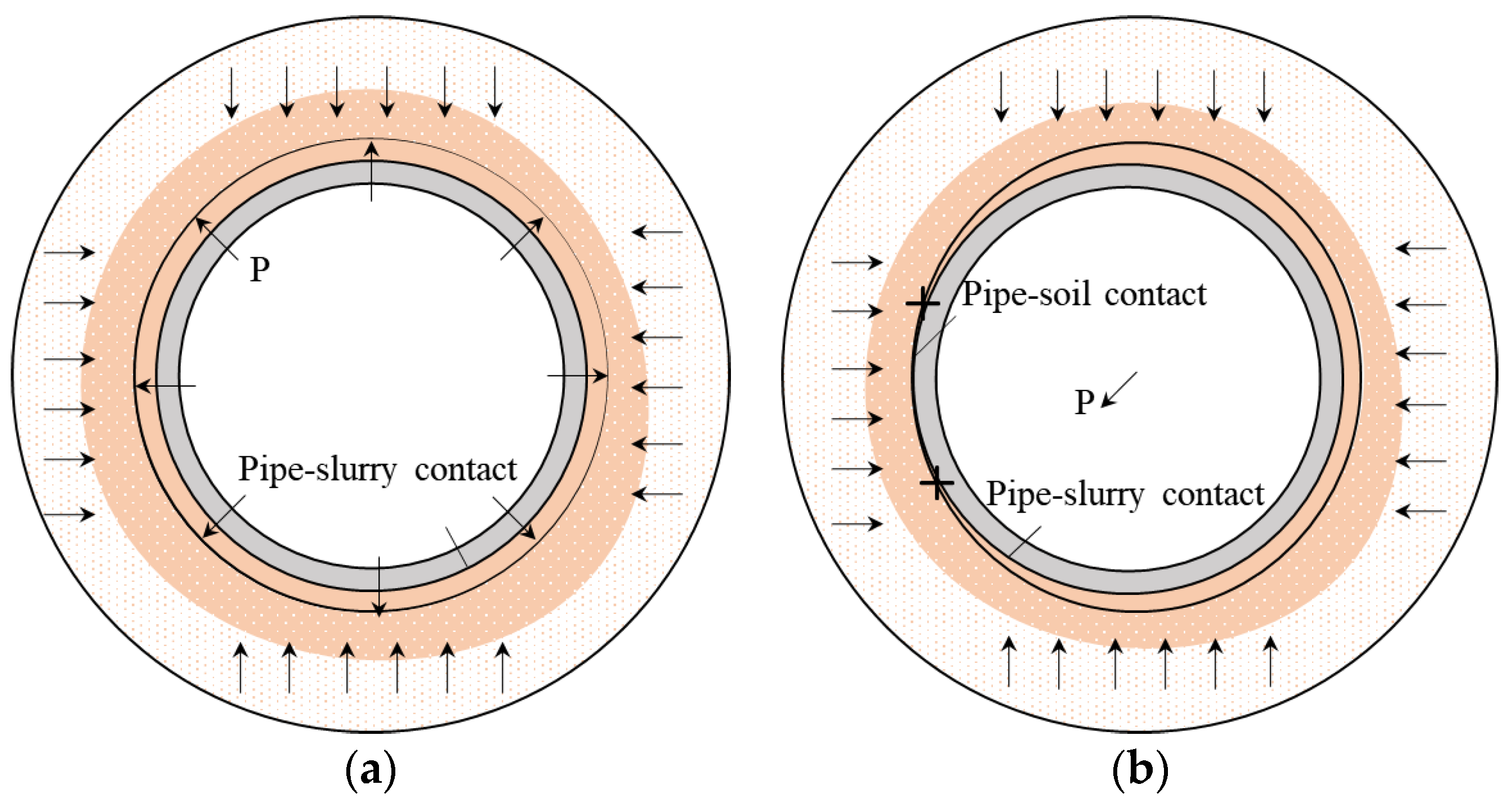
In slurry pipe jacking, the ideal scenario is that there is no mutual infiltration, or termination of the mutual infiltration between the slurry and the pipeline is surrounded by a cavity formed by the slurry layer (see Figure 1a). However, pipe–soil contact could occur because of various factors, such as the design, amount of grouting slurry, jacking speed, pipeline deviating from the intended line and level, irregular surrounding soil deformation, and interpenetration between the soil and slurry. Hence, a more common occurrence is when the excavated bore is stable, and part of the pipe inevitably comes into contact with the soil (see Figure 1b).
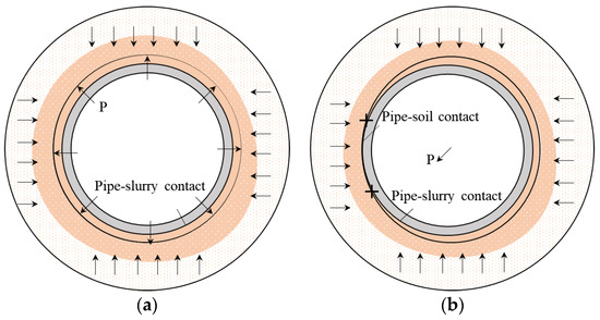
Figure 1.
(a) Full contact schematic diagram and (b) pipe–soil partial contact model in grouting.
The black arrows, in Figure 1, indicate the rough range and direction of the pressure of the surrounding soil on the pipe. And in Figure 1b, the black cross signs indicate the points of contact between the pipe and the soil. As shown in Figure 1b, in the case of grouting, some predictive friction resistance models are proposed. The Persson model, established by Ciavarella and Decuzzi, is suitable [18,31,33], as illustrated in Figure 2.
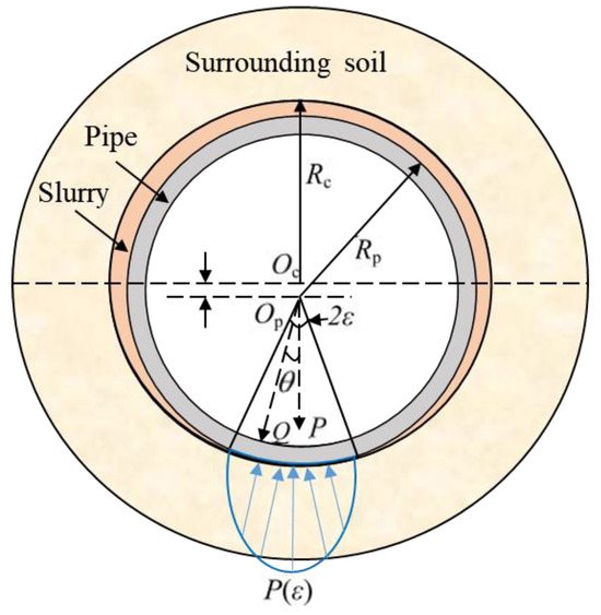
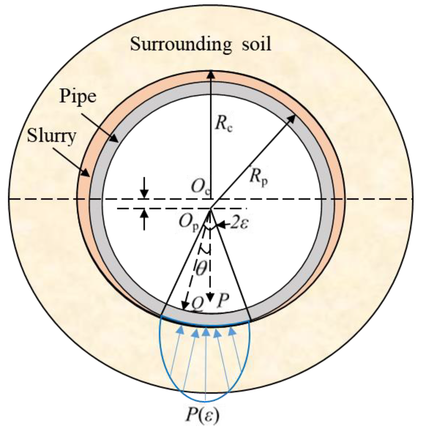
Figure 2.
Persson contact plane strain model.
The dashed lines and the black arrows marked in Figure 2 indicate the axis of the two non-concentric circles. The blue arrows indicate the range and direction of the pressure of the soil on the pipe when the pipe is in contact with the soil.
The central force, denoted as P, is primarily focused at the arc of contact between the pipe and the adjacent soil [18,30]. Equations (1) and (2) delineate the contact angle and pressure:
where is the Poisson’s ratio of the pipe, is the elastic modulus of the pipe (kPa), and is the radius of the excavation tunnel. and are related to the material parameters of the two contact bodies, respectively, and parameter b is related to the pipe–soil contact angle [18]. The computation of the associated parameters is delineated in Equation (3):
where denotes the Poisson’s ratio pertinent to the soil, is the elastic modulus of the pipe (kPa), and is the radius of the pipe. represents the contact pressure at location . Equation (1) can be determined by applying numerical analysis techniques [18,30]. P, the contact pressure, can be obtained by taking it into Equation (2). In Ref. [32], it was assumed that the angle of contact () between the pipe and the soil can be approximated as a fixed value of 180 degrees, and the aggregate contact pressure is approximately 1.35 times the intrinsic weight of the pipeline.
It can be seen from Equations (1) and (2) that the pipe–soil contact characteristics mainly depend on the elastic modulus and Poisson’s ratio of the pipe and soil. Taking into account the contact pressures at the interfaces of the pipe–soil and pipe–slurry [32], the frictional resistance per unit length of the pipe can be calculated as follows:
where represents the amplification coefficient of the contact pressure, which arises due to the uneven distribution of said pressure [32], and represents the contact pressure exerted per linear meter between the pipe and soil [31,33], which is 1.35 times the dead weight of the pipe, so is 1.35. is the friction coefficient of the pipe–soil. is the pipe-soil cohesion. is the mud pressure. is the friction coefficient between the pipe and the mud. This seems to be an appropriate method for forecasting the frictional resistance of pipes within layers of soft soil. Then, the calculation formula shown in Equation (4) is used to calculate the friction resistance per meter, combining the friction resistance between the pipe and soil and the pipe and slurry [18,30].
3. Automated Pipe Jacking Friction Resistance Identification and Warning System
3.1. Resistance Sensor Distribution
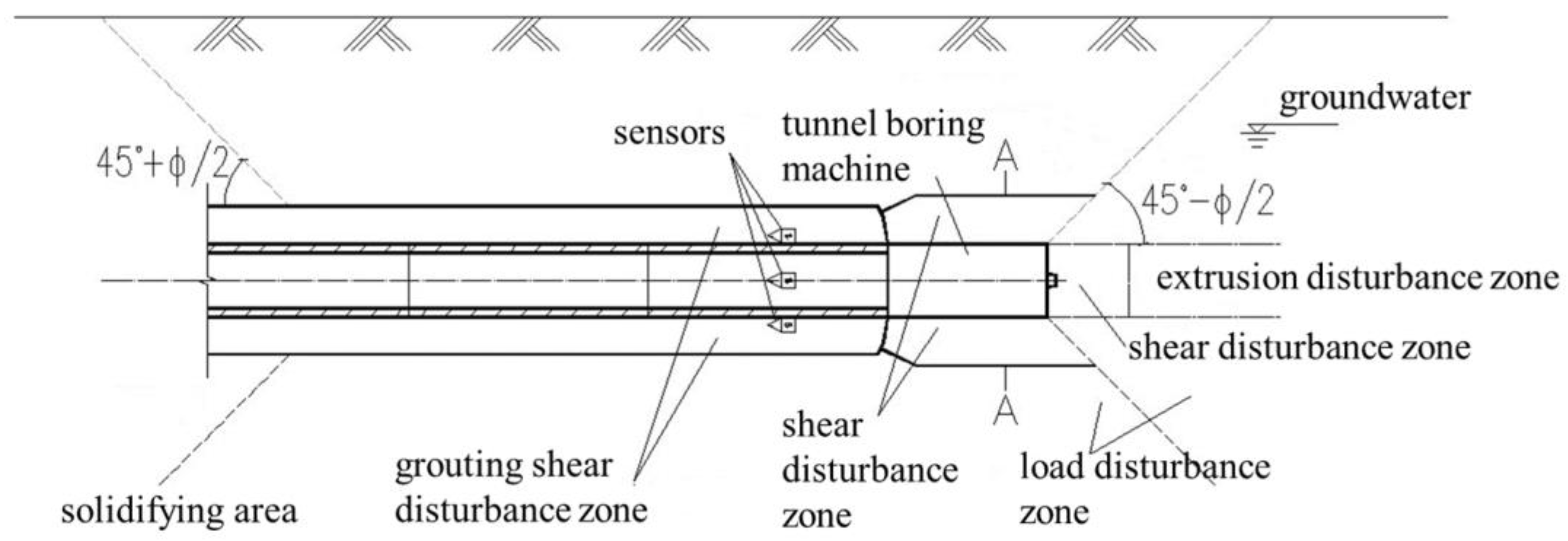
Mechanical analysis was conducted on the soil disturbed during the construction of the jacking pipes, particularly focusing on areas where significant frictional resistance occurs between the jacking pipe and the surrounding soil during the jacking process. This ensures the effectiveness of the resistance sensor installation locations. The disturbance analysis of the soil during pipe jackingis shown in Figure 3 and Figure 4.

Figure 3.
Longitudinal disturbance soil partition and resistance sensor installation location.
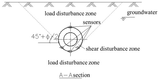
Figure 4.
Lateral disturbance soil partition and resistance sensor installation location.
The soil disturbed during pipe jacking construction can be divided into seven distinct disturbance zones, as shown in Figure 3 and Figure 4. These are the compression disturbance zone, shear disturbance zone (front/back), unloading disturbance zone (top/bottom), grouting shear disturbance zone, and consolidation zone. During the jacking process, the frictional resistance between the pipe jacking shell and the surrounding soil generates a force that results in a shear disturbance zone in the soil surrounding the tunnel boring machine. This zone has a relatively smaller range than other zones [25,34,35]. When no grouting is applied, the soil in the grouting shear disturbance zone experiences shear friction resistance between the pipeline and surrounding soil, leading to a movement back and forth along the pipeline axis during the construction process [36]. After grouting, the slurry transforms the dry friction between the pipeline and soil into wet friction, thus reducing the frictional resistance and supporting the surrounding soil, and reducing the soil deformation caused by pipe jacking construction. Taking all of these factors into consideration, the installation positions of the sensors were determined, as shown in the sensor location diagrams in Figure 3 and Figure 4.
3.2. Design of an Automated Pipe Jacking Friction Resistance Identification and Warning System
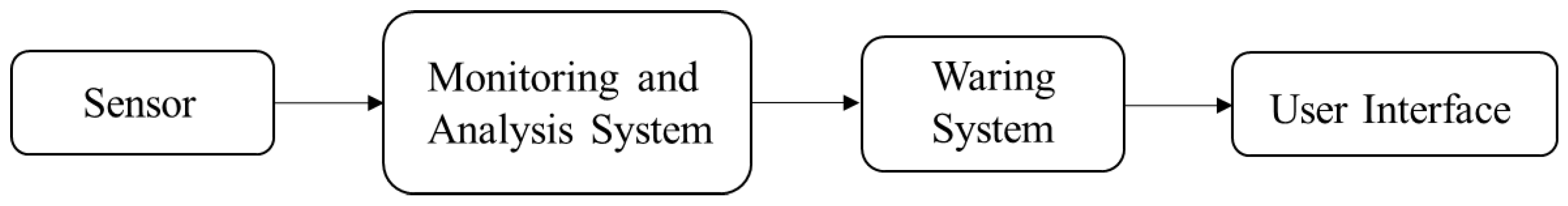
The automatic resistance identification and warning system, as depicted in Figure 5, comprises several key components.
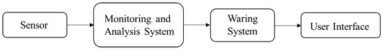
Figure 5.
Fundamental structure of the system.
The sensors, which are primarily employed to gauge the pressure during the pipe jacking construction process, form the first line of data collection. These raw data are then harvested by the data acquisition unit, which uses digital converters and microcontrollers to transform the sensor signals into a digital format.
The digitized data are subsequently transmitted to the monitoring and analysis system via the communication module, which employs various communication technologies. The monitoring and analysis system, equipped with specialized software, performs real-time monitoring and analysis of the collected data, processing and visualizing it for further use.
The warning system, a crucial component of the setup, sets thresholds based on the data from the construction site. It employs statistical analysis, machine learning, or artificial intelligence technology to identify any anomalies in resistance.
The user interface serves as a visual representation of real-time data, resistance identification situations, and warning information, presenting it to the operator in an easily interpretable format.
Resistance sensors are capable of the real-time monitoring of resistance during the jacking process. The collected resistance is then transmitted to the detection host through a resistance collector via a communication line. The detection host receives the resistance signal, stores it, and plots the complete resistance curve. The resistance display visually reflects the resistance distribution during pipe jacking. The shape of the resistance sensor and the architecture of the automatic resistance identification and warning system are shown in Figure 6.
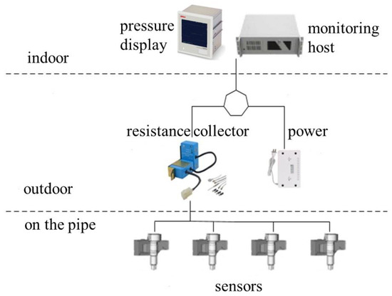
Figure 6.
Diagram of the automatic resistance identification and warning system.
The working principle for the resistance sensor is that the elastic component undergoes elastic deformation under external force, causing conversion elements, such as the resistance transducer attached to its surface, resulting in a change in the resistance value. This resistance change is then converted into an electrical signal through the corresponding measurement circuit, completing the process of converting the external force into an electrical signal. The jacking resistance during the construction process of pipe jacking is calculated according to resistance calculation Equation (4). The resistance sensors, developed by the Wauteco company, consist of soil pressure sensor modules that have undergone LGA packaging and assembly with the pressure modules. This design enables the sensors to provide calibrated output signals at a predetermined ratio. The resistance collector, also developed by the Wauteco company, then receives the signals from sensors.
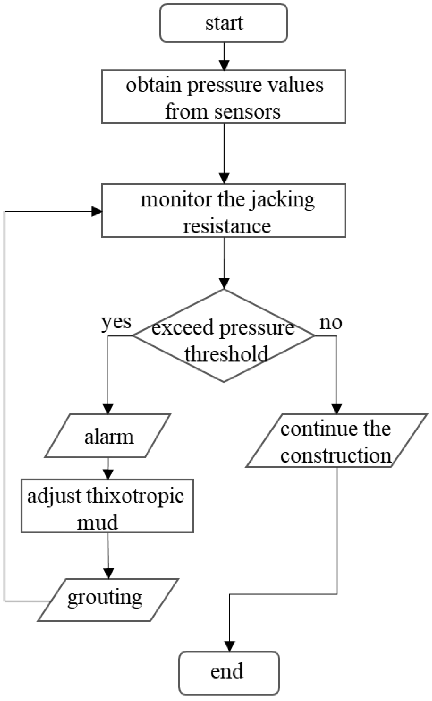
The resistance data are transmitted in real time to the indoor monitoring terminal through a communication line. In the monitoring host, the resistance pre-alarm warning value is set through the warning system. Once the detected resistance exceeds the threshold, an automatic alarm is triggered to promptly notify the operators and maintenance personnel to analyze and understand the resistance status of the pipe jacking machine. This allows for timely maintenance and grouting adjustment. The control process is illustrated in Figure 7.

Figure 7.
Diagram of the resistance threshold pre-alarm control process.
3.3. Construction Methods with a Resistance Identification and Warning System
The construction processes for the automated friction resistance identification and warning system and for pipe jacking are listed in steps, as follows:
- (1)
- The installation of resistance sensors on the outer wall of the jacking pipe according to the designated positions, and their connection, with data cables, power cables, a monitoring host, and their display.
- (2)
- Near the tunnel entrance, removal of the steel sheet piles when the jacking machine is 200 mm away from the tunnel entrance wall, and quick advance of the tunneling machine into the working face.
- (3)
- Completion of the following steps: installation of guide rails—installation of infrared alignment devices—installation of reinforced backrest—fixing of jack feet and installation of jacks—connection of hydraulic cylinders—hoisting of the tunneling machine as well as pipe sections—hoisting of the crown plate—pipe jacking and other related procedures.
- (4)
- Performance of actions to ensure pressure grouting and displacement of the variable slurry. Determination of the slurry ratio based on the initial plan and determination of the grouting pressure based on the depth of the pipeline and the groundwater level.
- (5)
- The total grouting volume should not be less than 2% of the volume of the annular space outside the pipe. To consider slurry losses, continuous grouting must be performed regularly to ensure the integrity of the slurry jacket.
- (6)
- Monitor the jacking process, including preliminary, jacking, and completion measurements. Measurements must be taken every 50 cm of jacking, with frequent adjustments. The correction angle should be kept within 10’ to 20’, not exceeding 1°. Measurements should be promptly recorded and submitted for review at the end of each pipe jacking section.
- (7)
- Identification and control of jacking resistance. Sensors in the jacking process automatically identify the jacking resistance. The pressure sensor automatically detects pressure during pipe jacking construction. According to formula (4), the frictional resistance during the jacking process is calculated, resulting in the actual resistance value. When the resistance value exceeds the pre-alarm threshold, the system automatically triggers an alarm, reminding construction personnel to adjust the resistance by improving the variable slurry. At this point, soil condition analysis at the construction site is required to optimize the slurry ratio and modify it, accordingly, reducing frictional resistance to achieve smooth jacking.
4. Engineering Case
4.1. Project Background and Geological Conditions
The construction site of the third section of the Black and Odorous Water Body Comprehensive Treatment Project is situated within the Han River Economic Development Zone in Hubei Province, China. The project construction is segmented into different zones, and construction is conducted in the corresponding zones. The project duration is set at 180 calendar days. The project comprised sub-projects such as ground pipeline excavation, masonry valve chambers, and road restoration. The amount of work required for the project is immense, while the project duration is rather short, which makes top pipe construction challenging.
Furthermore, top pipe construction is divided into two sections: WX2–WX13 and WX23–WX24, with a total length of approximately 480 m. The overall project investment amounts to CNY 1,790,571.6. The WX2–WX13 section lays approximately 432 m of φ1000 third-grade reinforced concrete socketed pipes, and the WX23–WX24 section lays approximately 48 m of φ800 third-grade reinforced concrete socketed pipes. The terrain along the pipeline passage slopes mildly from northwest to southeast over a plain lake area characterized by low-lying topography and silty soil.
The soil parameters were determined through direct shear tests on soil samples obtained from the construction site. The strata of the WX2–WX13 section comprise clay, sandy soil, and silt soil, as depicted in Table 1 and Figure 8. Figure 8 shows the strata conditions, and the red line and arrow indicate the jacking direction

Table 1.
Summary of soil characteristics in the WX2–WX13 section.
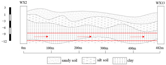
Figure 8.
WX2–WX13 stratigraphic section.
The geological layers from top to bottom are as follows: clay (3.5 m thick), sandy soil (0.5 m thick), and silty soil (0.5 m thick). The pipe jacking passes through clay, sandy soil, and silt at elevations between −7.5 and −11.5 m.
The unevenness and rheological thixotropy properties of the clay therefore make pipe jacking construction risky. The pipe might sink or deform because of the poor stability of sandy soil. However, the silt layer can provide solid support and reduce the risk of pipe sinking and deformation.
4.2. Materials and Equipment
The automated friction resistance identification and warning system construction method was applied in the Black and Odorous Water Body Comprehensive Treatment Project in the Han River zone. The section through which the pipe jacking pipeline passes is topographically characterized by a gentle slope from northwest to southeast and is in a plain lake area with low-lying terrain. The soil in this area comprises silt clay layers. Based on the soil conditions, a slurry ratio for the variable slurry was formulated, which was composed of sodium-based bentonite, water, caustic soda, and N, N-dimethyl acrylamide copolymer.
Pressure-sensing elements require high-quality and high-strength steel materials. In addition, special communication cables are used for the resistance sensors. The grouting pipeline consists of galvanized steel pipes and rubber hoses with a diameter of 38 mm. The main equipment for this construction method includes resistance sensors, resistance collectors, resistance displays, detection hosts, and a grout buffer tank. The specific models and specifications are presented in Table 2.
Table 2.
Key equipment and technical parameters table.
4.3. Calculation of Frictional Resistance and Grouting Adjustment
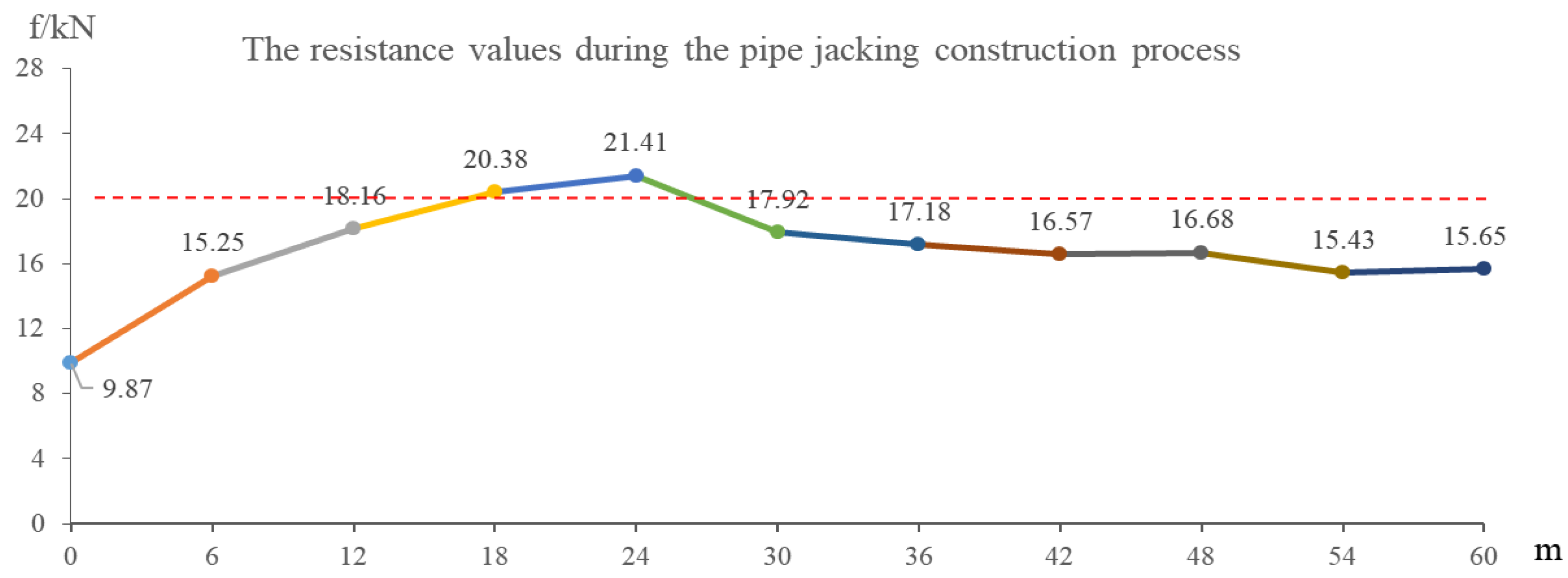
Based on the equipment, soil parameters (shown in Table 1) at the construction site, and pressure sensor data, the jacking construction resistance value f can be calculated using the calculation formula shown in Equation (4). Based on general experience from the construction site, the resistance warning value is initially set at 20 kN. The monitored resistance values during the construction process are shown in Figure 9.
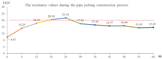
Figure 9.
Resistance values.
As presented in Figure 9, the analysis of the resistance values reveals that the design and implementation of the automated pipe jacking friction resistance identification and warning system can effectively monitor resistance in real time during the jacking process. The frictional resistance gradually increases from the starting point to a point 24 m away. The situation in which this resistance continuously increases at the beginning of the construction phase is consistent with reality. When the resistance value reaches the preset warning value of 20 kN, an alarm is triggered to indicate increased resistance. At this point, it is necessary to timely adjust field construction conditions, such as the rheological properties of the slurry mix. As seen from the graph above, after adjusting the rheological properties of the slurry, the resistance value during pipe jacking decreases continuously, effectively promoting long-distance jacking.
5. Conclusions
This paper introduces an innovative automatic resistance identification and warning system specifically designed for pipe jacking construction. First, an analysis of the resistance-impacting factors during the pipe jacking construction process was conducted, drawing upon a review of the existing literature. Considering the varied factors influencing pipe jacking resistance, it was suitable to choose the Persson calculation model based on Persson theory from several existing resistance calculation models. On the basis of the Persson model, the calculation formula for pipe jacking friction resistance was given. Second, an automatic resistance identification and warning system was proposed that encompasses several key aspects:
- (1)
- Sensor placement is strategically determined by analyzing the stress patterns in the soil surrounding the pipe jacking.
- (2)
- The foundational structure of the resistance identification and warning system is constructed.
- (3)
- The control process for the resistance warning is provided.
- (4)
- A construction approach during pipe jacking is presented, which integrates with the resistance identification and warning system.
Third, the resistance identification and warning system was tested through a practical application in the Hubei Han River Black and Odorous Water Body Comprehensive Treatment Project in China. It was found that at the beginning stage of pipe jacking construction, as the jacking distance increases, the jacking resistance continuously increases, which supports the findings of a study conducted by Ye et al. [23,24,30]. When the frication resistance value reaches the preset warning value, an alarm is triggered. After adjusting the proportion of thixotropic mud, the resistance value starts to decrease.
In summary, the development of an automated pipe jacking friction resistance identification and warning system can provide a reference for the development of intelligent pipe jacking and contribute to improving construction safety levels. Because the warning value is established from construction experience data, further research is needed to study the application of artificial intelligence algorithms, such as deep learning, for the identification and prediction of resistance thresholds.
Author Contributions
Conceptualization, L.-H.J. and B.-J.W.; methodology, L.-H.J. and B.-J.W.; validation, L.-H.J.; writing—original draft preparation, B.-J.W.; writing—review and editing, L.-H.J., X.-Z.Z. and S.C. All authors have read and agreed to the published version of the manuscript.
Funding
The authors acknowledge financial support from the National Natural Science Foundation of China (No. 52179136).
Institutional Review Board Statement
Not applicable.
Informed Consent Statement
Not applicable.
Data Availability Statement
The data presented in this study are available in Development and Field Application of an Automated Pipe Jacking Friction Resistance Identification and Warning System in Construction.
Conflicts of Interest
The authors declare no conflict of interest.
References
- Namli, M.; Guler, E. Effect of Bentonite Slurry Pressure on Interface Friction of Pipe Jacking. J. Pipeline Syst. Eng. Pract. 2017, 8, 04016016. [Google Scholar] [CrossRef]
- Ji, X.; Ni, P.; Barla, M. Analysis of jacking forces during pipe jacking in granular materials using particle methods. Undergr. Space 2019, 4, 277–288. [Google Scholar] [CrossRef]
- Ji, X.; Zhao, W.; Ni, P.; Barla, M.; Han, J.; Jia, P.; Chen, Y.; Zhang, C. A method to estimate the jacking force for pipe jacking in sandy soils. Tunn. Undergr. Space Technol. 2019, 90, 119–130. [Google Scholar] [CrossRef]
- Wen, K.; Shimada, H.; Zeng, W.; Sasaoka, T.; Qian, D. Frictional analysis of pipe-slurry-soil interaction and jacking force prediction of rectangular pipe jacking. Eur. J. Environ. Civ. Eng. 2020, 24, 814–832. [Google Scholar] [CrossRef]
- Liu, J.; Wang, X.; Cheng, H.; Fan, H. Orthogonal Design and Microstructure Mechanism Analysis of Novel Bentonite Polymer Slurry in Pipe Jacking. Polymers 2023, 15, 1461. [Google Scholar] [CrossRef]
- Zeng, C.; Xiao, A.; Liu, K.; Ai, H.; Chen, Z.; Zhang, P. Experimental Study on the Influence of Slurry Concentration and Standing Time on the Friction Characteristics of a Steel Pipe-Soil Interface. Appl. Sci. 2022, 12, 3576. [Google Scholar] [CrossRef]
- Ma, P.; Shimada, H.; Sasaoka, T.; Hamanaka, A.; Moses, D.N.; Dintwe, T.K.M.; Matsumoto, F.; Ma, B.; Huang, S. A new method for predicting the friction resistance in rectangular pipe-jacking. Tunn. Undergr. Space Technol. 2022, 123, 104338. [Google Scholar] [CrossRef]
- Liu, K.; Xiao, A.; Zhang, P.; Zhou, H.; Chen, Z.; Xu, T.; Ma, B.; Ai, H.; Wang, Q. Study on mechanical response of steel pipe jacking considering the effect of pipe sticking. Tunn. Undergr. Space Technol. 2022, 127, 104617. [Google Scholar] [CrossRef]
- Liu, S.; Zhang, B.; Zhang, X.; Fan, D.; Wang, H.; Yu, M. Formulation optimization and performance analysis of the thixotropic slurry for large-section rectangular pipe jacking in anhydrous sand. Constr. Build. Mater. 2022, 357, 129380. [Google Scholar] [CrossRef]
- Wang, Y.; Zhang, D.; Fang, Q.; Liu, X.; Wang, J. Analytical Solution on Ground Deformation Caused by Parallel Construction of Rectangular Pipe Jacking. Appl. Sci. 2022, 12, 3298. [Google Scholar] [CrossRef]
- Roussel, N. A thixotropy model for fresh fluid concretes: Theory, validation and applications. Cem. Concr. Res. 2006, 36, 1797–1806. [Google Scholar] [CrossRef]
- Mahaut, F.; Mokeddem, S.; Chateau, X.; Roussel, N.; Ovarlez, G. Effect of coarse particle volume fraction on the yield stress and thixotropy of cementitious materials. Cem. Concr. Res. 2008, 38, 1276–1285. [Google Scholar] [CrossRef]
- Cheng, W.-C.; Wang, L.; Xue, Z.-F.; Ni, J.C.; Rahman, M.M.; Arulrajah, A. Lubrication performance of pipejacking in soft alluvial deposits. Tunn. Undergr. Space Technol. 2019, 91, 102991. [Google Scholar] [CrossRef]
- Zhang, P.; Behbahani, S.S.; Ma, B.; Iseley, T.; Tan, L. A jacking force study of curved steel pipe roof in Gongbei tunnel: Calculation review and monitoring data analysis. Tunn. Undergr. Space Technol. 2018, 72, 305–322. [Google Scholar] [CrossRef]
- Ji, X.; Ni, P.; Barla, M.; Zhao, W.; Mei, G. Earth pressure on shield excavation face for pipe jacking considering arching effect. Tunn. Undergr. Space Technol. 2018, 72, 17–27. [Google Scholar] [CrossRef]
- Li, C.; Zhong, Z.; Liu, X.; Tu, Y.; He, G. Numerical simulation for an estimation of the jacking force of ultra-long-distance pipe jacking with frictional property testing at the rock mass-pipe interface. Tunn. Undergr. Space Technol. 2019, 89, 205–221. [Google Scholar] [CrossRef]
- Zhang, P.; Feng, X.; Zeng, C.; Ariaratnam, S.T. Field performance of steel pipes during curve jacking in Gongbei tunnel. Tunn. Undergr. Space Technol. 2022, 128, 104585. [Google Scholar] [CrossRef]
- Chen, P.; Liu, X.; Deng, Z.; Liang, N.; Du, L.; Du, H.; Huang, Y.; Deng, L.; Yang, G. Study on the pipe friction resistance in long-distance rock pipe jacking engineering. Undergr. Space 2023, 9, 173–185. [Google Scholar] [CrossRef]
- Liu, J.; Cheng, H.; Cai, H.; Wang, X. Design and Analysis of Grouting Pressure in Slurry Pipe Jacking Based on the Surrounding Soil Stability Mechanical Characteristics. Geofluids 2022, 2022, 4697730. [Google Scholar] [CrossRef]
- Guo, W.; Hong, K.; Gao, P.; Li, F.; Li, S.; Zhao, X. Status Quo and Prospects of Tunnel Intelligent Construction in China. Tunn. Constr. 2023, 43, 549–562. [Google Scholar]
- Du, J.; Zhang, J.; Hu, M.; Gan, L. Literature Review on Human Factors involved in Intelligent Shield Construction. Tunn. Constr. 2023, 8, 1269–1281. [Google Scholar]
- Chen, X.; Fu, Y.; Chen, X.; Xiao, H.; Bao, X.; Pang, X.; Wang, X. Progress in Underground Space Construction Technology and Technical Challenges of Diguital Intelligence. China J. Highw. Transp. 2022, 35, 1–12. [Google Scholar]
- Ye, Y.; Peng, L.; Zhou, Y.; Yang, W.; Shi, C.; Lin, Y. Prediction of Friction Resistance for Slurry Pipe Jacking. Appl. Sci. 2020, 10, 207. [Google Scholar] [CrossRef]
- Ye, Y.; Peng, L.; Yang, W.; Zou, Y.; Cao, C. Calculation of Friction Force for Slurry Pipe Jacking considering Soil-Slurry-Pipe Interaction. Adv. Civ. Eng. 2020, 2020, 6594306. [Google Scholar] [CrossRef]
- Feng, X.; Zhang, Y.; Yuan, X.; Zhang, P. An Experimental Study on Frictional Properties of Concrete Pipe-Soil Interface. J. Pipeline Syst. Eng. Pract. 2022, 13, 04022004. [Google Scholar] [CrossRef]
- Cui, G.-J.; Xie, J.-S.; Sun, Y.-H.; Gao, Y.-J. Analysis and Prediction of the Factors Influencing Postconstruction Surface Deformation of Pipe-Jacking Tunnel in Soft Clay Strata in China. Adv. Civ. Eng. 2023, 2023, 6474415. [Google Scholar] [CrossRef]
- Wang, J.; Wang, K.; Zhang, T.; Wang, S. Key aspects of a DN4000 steel pipe jacking project in China: A case study of a water pipeline in the Shanghai Huangpu River. Tunn. Undergr. Space Technol. 2018, 72, 323–332. [Google Scholar] [CrossRef]
- Deng, Z.; Liu, X.; Zhou, X.; Yang, Q.; Chen, P.; de la Fuente, A.; Ren, L.; Du, L.; Han, Y.; Xiong, F.; et al. Main engineering problems and countermeasures in ultra-long-distance rock pipe jacking project: Water pipeline case study in Chongqing. Tunn. Undergr. Space Technol. 2022, 123, 104420. [Google Scholar] [CrossRef]
- Peerun, M.I.; Ong, D.E.L.; Desha, C. A strategic review on enhanced DEM simulation and advanced 3-D particle printing techniques to improve pipe-jacking force prediction. Tunn. Undergr. Space Technol. 2022, 123, 104415. [Google Scholar] [CrossRef]
- Ciavarella, M.; Decuzzi, P. The state of stress induced by the plane frictionless cylindrical contact. II. The general case (elastic dissimilarity). Int. J. Solids Struct. 2001, 38, 4525–4533. [Google Scholar] [CrossRef]
- Ciavarella, M.; Decuzzi, P. The state of stress induced by the plane frictionless cylindrical contact. I. The case of elastic similarity. Int. J. Solids Struct. 2001, 38, 4507–4523. [Google Scholar] [CrossRef]
- Zhang, P.; Ma, B.-S.; Zeng, C.; Tan, L.-X. Numerical model for jacking force based on pipe-soil contact characteristics. Chin. J. Geotech. Eng. 2017, 39, 244–249. [Google Scholar]
- Zhou, H.; Huang, S.; Zhang, P.; Ma, B.; Ma, P.; Feng, X. Prediction of jacking force using PSO-BPNN and PSO-SVR algorithm in curved pipe roof. Tunn. Undergr. Space Technol. 2023, 138, 105159. [Google Scholar] [CrossRef]
- Wang, Z.; Zhao, W.; Wang, H.; Chen, Y.; Bai, Q.; Li, S. Analysis of the influence of geometrical parameters of circular steel pipe with flange plate on the jacking force. Undergr. Space 2022, 7, 324–336. [Google Scholar] [CrossRef]
- Wu, S.; Li, X.; Jiang, P.; Xu, H.; Min, F. Dewatering characteristics of waste slurry from pipe jacking based on improved vacuum filtration method. Tunn. Undergr. Space Technol. 2022, 130, 104727. [Google Scholar] [CrossRef]
- Westgate, Z.J.; White, D.J.; Randolph, M.F. Field observations of as-laid pipeline embedment in carbonate sediments. Géotechnique 2012, 62, 787–798. [Google Scholar] [CrossRef]


Disclaimer/Publisher’s Note: The statements, opinions and data contained in all publications are solely those of the individual author(s) and contributor(s) and not of MDPI and/or the editor(s). MDPI and/or the editor(s) disclaim responsibility for any injury to people or property resulting from any ideas, methods, instructions or products referred to in the content. |
© 2023 by the authors. Licensee MDPI, Basel, Switzerland. This article is an open access article distributed under the terms and conditions of the Creative Commons Attribution (CC BY) license (https://creativecommons.org/licenses/by/4.0/).