Article

Deformation and Stress Law of Surrounding Rock for a Bifurcated Tunnel with a Super-Large Section: A Case Study

Department of Safety Science and Engineering, School of Civil and Resource Engineering, University of Science and Technology Beijing, Beijing 100083, China
*
Author to whom correspondence should be addressed.
Appl. Sci. 2023, 13(23), 12852; https://doi.org/10.3390/app132312852
Submission received: 8 November 2023 / Revised: 23 November 2023 / Accepted: 27 November 2023 / Published: 30 November 2023
(This article belongs to the Section Civil Engineering)

Abstract

:
The construction method of transitioning from a small cross-section to excavating a super-large cross-section tunnel plays a crucial role in the quality of the final super-large cross-section tunnel and the safety of the tunnel structures and workers during the construction process. The Shenzhen Liantang Bifurcated Tunnel, with a maximum cross-sectional area of 428.4 m2, was the largest cross-sectional tunnel constructed in China in 2018, and there are few engineering projects that can serve as references. To enhance construction safety and achieve the transformation from a two-lane tunnel to a five-lane tunnel, this paper proposes two tunneling methods, namely, the reverse top-heading method and the advance climbing method. Moreover, numerical simulation using MIDAS GTS/NX software was adapted to compare and analyze the stress and deformation characteristics of the surrounding rock in the construction stages using the two methods. The simulation shows that the advance climbing method is more suitable for the construction of the Liantang tunnel. Through on-site monitoring and measurement, the data of peripheral rock vault subsidence, peripheral convergence, and pressure of the supporting structure were assessed. The results show that the maximum values of peripheral rock vault subsidence and peripheral convergence displacement are located in the permissible range of road tunnel vault subsidence. This further verifies the reasonableness of the advance climbing method. This paper not only provide a basis for the construction of the Liantang tunnel but also serves as a reference for construction methods and typical cases for similar super-large-section tunnel projects.

1. Introduction

In recent years, with the increasing demand for underground transportation projects, the development of highway tunnels has been rapid. The construction of four-lane or larger cross-section highway tunnels has become a trend. Based on the characteristics and purposes of such projects, four-lane or larger cross-section highway tunnels can be divided into three major categories [1]: conventional new four-lane highway tunnels, in situ expansion of four-lane highway tunnels, and four-lane or larger bifurcated tunnels. Among these, bifurcated tunnels are tunnel projects where two lines intersect or separate, often occurring at the junction of bridges or tunnels and underground interchange ramps. They are often used as transition sections along with large cross-section tunnels and tunnels with small clearances. Therefore, bifurcated tunnels have the characteristics of large cross-sections and complex structures.
According to statistics, from 2005 to 2020, there were 12 four-lane or larger bifurcated tunnels completed and under construction in China [2]. Typical projects include the Qingdao Jiaozhou Bay Subsea Tunnel [3], Xiamen Lu’ao Road Bifurcated Tunnel [4], and Yunnan Hutiaoxia Bifurcated Tunnel [5]. Because of rapid development and application, the research focuses and popular topics have shifted to optimizing construction methods for large cross-section tunnels [6,7,8], the dynamic construction mechanics of surrounding rock [9,10,11], and the determination of support structure parameters [12,13]. A bifurcated tunnel with a super-large section consists of three segments: the large cross-section construction segment, the small-clearance tunnel construction segment, and the variable cross-section transition construction segment. Of these, the variable cross-section transition construction segment involves excavating tunnels with at least three cross-sections. During construction, one must consider the stability of the surrounding rock in the large cross-section area and the presence of rock in the small-clearance section. Simultaneously, ensuring the rationality of the tunnel cross-section transition construction method and construction safety is of utmost importance. This segment is the most complex and hazardous of these three segments. Hence, we focus on the study of variable cross-section transition construction in this paper.
The transition segment of the variable cross-section involves two cases: construction from a small cross-section to a large cross-section, and construction from a large cross-section to a small cross-section. It is evident that excavating from a large to a small cross-section is simpler. However, for some complex tunnel structures, it is necessary to transition from a small to a large cross-section. During this process, the transition of the arch height and area differences must be managed, and the rational sequence of operations will determine the safety of the transition segment. Hu [14] and Yan [15] proposed bidirectional construction techniques for large-span small-clearance tunnels in the Hangzhou Zizhi Bifurcated Tunnel. They used auxiliary construction adits for small cross-section tunnel construction, climbed to the top within the large cross-section tunnel, and completed the transition from a small to a large cross-section. Zhang et al. [16] introduced the reverse excavation method in the Yang’an Bifurcated Tunnel, entering the large cross-section tunnel through inclined shafts to achieve sequence alignment, and evaluated the feasibility using numerical simulation. Based on the Shantou Bay subsea shield tunnel, Liu et al. [17] used a refined lining model considering the details of lining components, and adopted XFEM and CDP (Concrete Damage Plasticity) constitutive models in part of the model for stress analysis and damage development. Hu et al. [18] proposed an improved Kriging filtering algorithm in the NATM tunnel, utilizing 3D laser scanning and ranging point cloud data to estimate the full-space deformation field of tunnel excavation. Due to the multiple tunnel cross-sections and extensive excavation spans, there are mutual interferences between various construction procedures during construction and the surrounding rock will undergo multiple disturbances [19]. The dynamic construction process’s mechanical behavior is highly complex, and the surrounding rock is prone to instability and even collapse [20], especially in the construction of non-symmetric small-clearance tunnels, which exhibit differences in mechanical characteristics [21,22]. Timely feedback on the support system’s stress characteristics is crucial to ensuring the safety of large-span tunnel construction [23]. Currently, research on the methods of transitioning from a small to a large cross-section in bifurcated tunnel construction is limited, particularly regarding the study of the stress and deformation characteristics of the surrounding rock during the construction process, and few research cases are available for reference.
This paper is based on the Shenzhen Liantang Bifurcated Tunnel project. The tunnel is a typical bifurcated tunnel with a super-large section, which involves a maximum cross-sectional area of 428.5 m2. It is the world’s largest cross-sectional road tunnel constructed by drilling and blasting, and was built in 2018 [24]. The maximum cross-section of the tunnel is designed for five lanes, which are connected to two and three lanes. During construction, excavation progressed from two lanes to five lanes. Combining common large-section tunnel excavation methods, this paper proposes two methods of variable cross-section construction, each of which undergoes a safety analysis. Additionally, a numerical simulation is used to establish a model for calculating the stress on the surrounding rock during the construction process. This analysis includes studying the deformation and stress characteristics of the surrounding rock in the bifurcated tunnel at different construction stages to determine the optimal construction approach. Finally, in practical engineering applications, the actual deformation and stress characteristics of the surrounding rock are measured and analyzed. The peak pressures and risk areas of initial support and secondary lining during the excavation process of large-section tunnels are determined. Therefore, the rationality and safety of the optimal construction scheme can be comprehensively evaluated.

2. Project Overview, Problems, and Solutions

A bifurcated tunnel with a super-large section is composed of multiple tunnels with different sizes. The transition of construction processes for these tunnels is intricate, particularly concerning the ambiguous method of variable cross-section excavation for tunnels larger than 400 m2. Currently, there are no construction technology standards available for reference. To address this critical issue of forming super-large cross-sectional tunnels from smaller to larger sections, this section proposes safe and efficient methods for variable cross-section excavation based on the structural characteristics of different cross-sectional segments within bifurcated tunnels. It covers project background, cross-sectional characteristics, construction plans, and safety-related considerations.

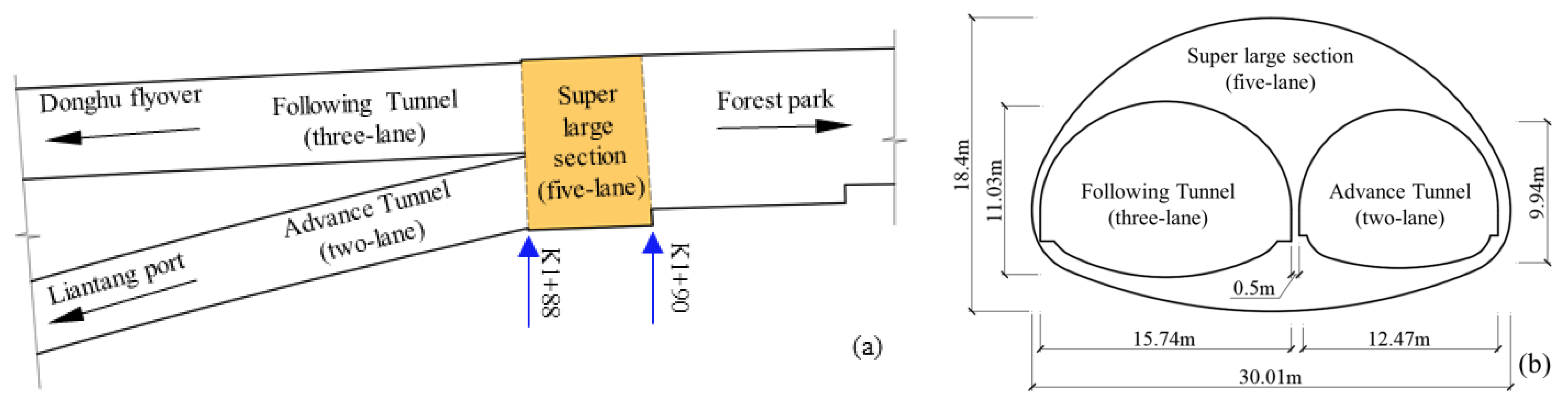
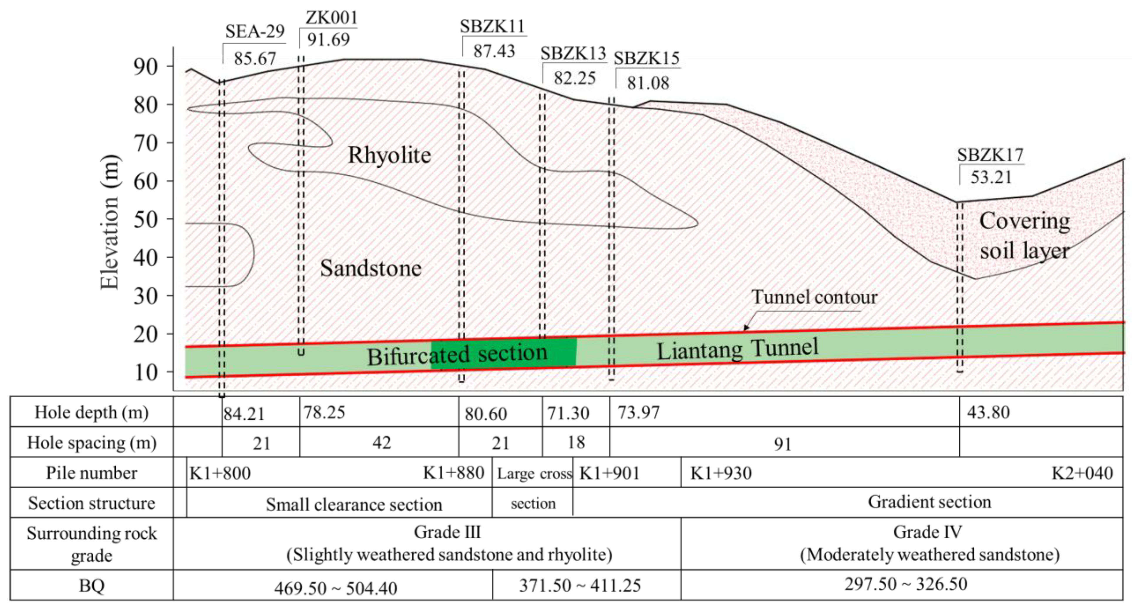
2.1. Engineering Background

The Liantang Tunnel is a crucial control project for the eastern transit expressway in Shenzhen. It starts within Xianhu Botanical Garden in Luohu District, Shenzhen, China, and ends at Liantang Port, which borders Hong Kong, China. The tunnel has a total length of 2.77 km and a design speed of 60 km/h. Furthermore, the tunnel is adjacent to Shenzhen Reservoir and Liantang residential area, with a nearest straight-line distance of 120 m between the construction workface and Shenzhen Reservoir. The Liantang tunnel is 2.65 km long. The tunnel’s left-lane bifurcation-out section is a typical bifurcation-out tunnel with a super-large cross-section that uses the “3-lanes and 2-lanes” interchange arrangement. All lanes converge into five lanes and then gradually convert to four lanes. It is China’s first subterranean highway interchange tunnel. Figure 1 shows the plan of the bifurcation-out section.
The bifurcated tunnel with a super-large section is formed by the convergence of a three-lane tunnel and a two-lane tunnel, resulting in a super-large-section five-lane tunnel (Figure 2a). The maximum section area is 428.5 m2, located in the section from K1+880 to K1+901, and it is the world’s largest highway tunnel constructed by the drilling and blasting method. The maximum span and crown height are 30 m and 18.4 m, respectively, with a height-to-span ratio of 0.61. The minimum thickness of the interlayered rock in the small-clearance section is 0.5 m, making it the second smallest clearance tunnel in the world. The section areas of the two-lane and three-lane tunnels are 100.4 m2 and 137.5 m2, respectively. The two lanes lead to the municipal road and the center of Liantang Port. The plan view and the sectional structure at the junction interface of the bifurcated tunnel are shown in Figure 2b.
According to the engineering geological exploration report of Liantang tunnel, the topography along the bifurcation tunnel is characterized by low hills and undulating terrain, with relatively intact landforms. The tunnel passes through mainly Carboniferous layered metamorphic sandstone and Jurassic rhyolite formations. The tunnel section is located in the foothills of low mountains with elevations below 100 m, and the slope of the mountains is gentle. The maximum depth of cover is approximately 90 m. The tunnel alignment is not within a high-stress zone, and the surrounding rock in the area consists mostly of moderately weathered sandstone, classified as a Class III rock mass. The rock mass exhibits well-developed joint fissures, and many of the fissure surfaces are stained with iron and manganese oxides. The groundwater is expected to be moist, dripping, or flowing during tunnel excavation in a linear fine water flow. The surrounding rock has a low level of stability. Medium and minor landslides may occur locally when the arch is unsupported, although the side wall is often secure. The longitudinal section of the main tunnel segment is shown in Figure 3.

2.2. Section Zoning Excavation Scheme

As mentioned above, due to the lack of design specifications for four-lane or larger tunnels, the construction methods of the bifurcated tunnel are designed to excavate from a small section to a larger section. The two-lane section of the tunnel (advance tunnel) is excavated first. For the excavation of the larger section, it is recommended to adopt dual-side wall excavation, while the two small-section tunnels of the bifurcated tunnel are excavated using a stepped approach, as shown in Figure 4. However, a specific plan for transitioning from the two-lane section to the larger section has not been provided.

2.3. Construction Design for the Bifurcation Tunnel

During the transition from the small-section tunnel to the large-section tunnel, there is a height difference of 5.9 m between the two-lane section and the crown of the large section. To transform from the “small section” with two lanes to the “super large section” with five lanes, it is necessary to achieve a spatial transition with a difference in excavation contour area of 320 m2 while eliminating the height difference. The impact of multi-step construction on the stability of the surrounding rock in the five-lane tunnel is crucial for the safety of the construction of the bifurcated tunnel with a super-large section. Therefore, the construction techniques for transitioning from two lanes to five lanes in terms of variable-section construction are key and challenging aspects.
Based on the structural characteristics of the bifurcation tunnel, two on-site excavation schemes have been proposed: one is the reverse top-heading method (RTM), which involves excavating an inclined pilot tunnel (IPT) from the inside of the five-lane tunnel to the crown; the other is the advance climbing method (ACM), which involves excavating the IPT in the two-lane tunnel from the outside of the large section. The specific construction methods and their characteristics are as follows.

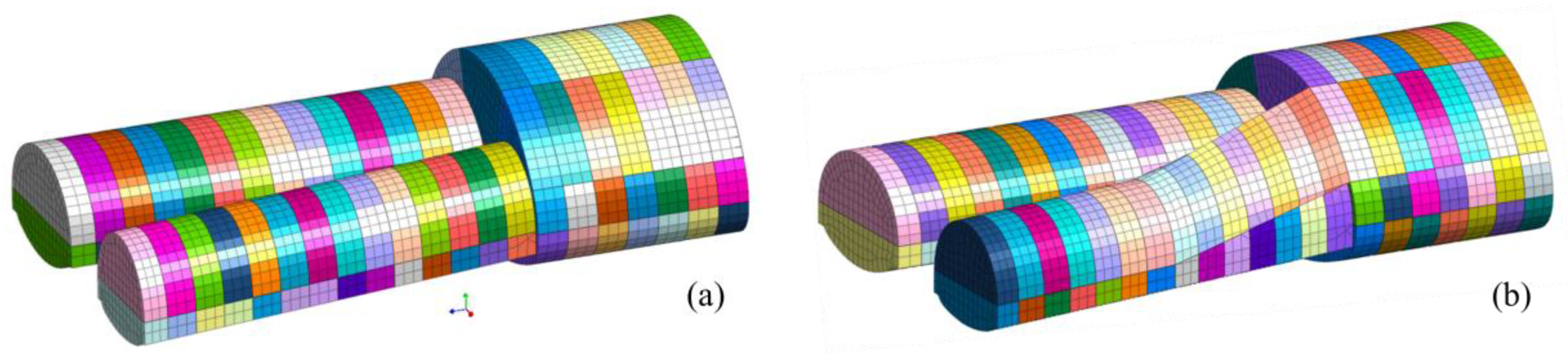
2.3.1. The Characteristic of RTM

As shown in Figure 5, the advance tunnel is initially excavated with two lanes, progressing normally until reaching the intersection with the maximum section. The intersection surface serves as the starting face for the IPT construction. In the early stage of large-section excavation, the IPT is constructed using stepped sections on the two-lane side. The IPT is constructed with a variable section until reaching the end of the large section. At this point, the section of the IPT aligns with one side of the large section’s single-side wall section. The area above the IPT where the large section has not yet formed is excavated in reverse until reaching the design contour. With this, the construction of the transitional section for the bifurcation tunnel’s variable section is completed. Subsequently, horizontal excavation is carried out to form the other side of the dual-side wall and the central drift, completing the excavation construction.
This method has the following characteristics:
(a)
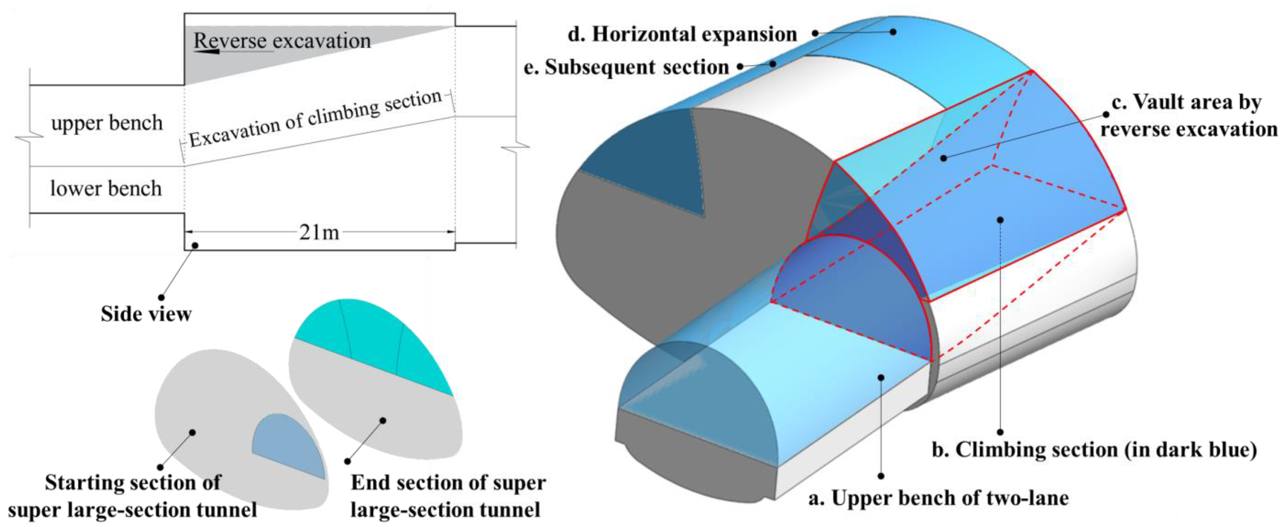
The angle of the IPT is a fixed value determined by the length of the large section. The climbing angle is a fixed value determined by the relationship between the two-lane section and the position of the large section on the plan. The shorter the length of the large-section segment, the steeper the climbing angle.
(b)
The difficulty lies in controlling the drilling angle, and there is a high risk factor for workers during construction. In step c of Figure 5, irregular arc-shaped thin rock layers require multiple blasts for excavation. When workers drill holes, the bottom of the drilling rig needs to be treated for debris, and a horizontal working platform needs to be installed. If horizontal drilling and blasting are used, it is difficult to control the drilling angle, which may lead to slabbing. If vertical drilling is adopted, controlling the depth of the borehole is challenging, and the downward-facing borehole opening is not conducive to charging and blocking, resulting in a high risk factor for workers.
(c)
Blasting in the vault area causes cumulative damage to the top of the large section, and the resulting debris blocks the tunnel entrance. During the excavation by reverse top heading blasting, the surrounding rock of the large section in this area undergoes multiple cumulative damages, affecting the stability of the surrounding rock of the large-section tunnel. At the same time, the direction of the blasted rock fragments from the top will be downwards, and the resulting debris will block the IPT entrance, forming a sealed space that hinders subsequent operations and affects the construction schedule of follow-up work.
(d)
Changes in the original zoning plan for the super-large section result in changes to the sequence of support operations. Changes in the partitioning plan for the dual-side walls of the large section lead to changes in subsequent work processes and the sequence of support operations. For large sections over 400 m2, the synchronization of construction sequences and support plays an important role in the stability of the surrounding rock.

2.3.2. The Characteristic of ACM

The excavation of the two-lane tunnel stops at a certain position before reaching the large section. The IPT is excavated in advance from the two-lane stepped section to the end face of the large section, aligning with one side wall section, as shown in Figure 6. The climbing of the advance ramp causes the elevation of the advance tunnel’s climbing section to be higher than the design elevation of the two-lane section. Additionally, the profile of the stepped section differs from the single-side wall profile of the large section. Therefore, backfilling and support operations are required in the climbing section after excavation is completed. For sections with different profiles, the climbing section is divided into two parts: the regular climbing section and a variable-section construction approach in the vicinity of the large section. The variable-section construction is used to connect with one side wall working face of the large section, completing the transitional section for the bifurcation tunnel’s variable section. After the single-side wall of the large section is formed, horizontal excavation is carried out to create the other side wall and the central drift, followed by excavation and support operations.
Compared to the first method, this method has the following characteristics:
(a)
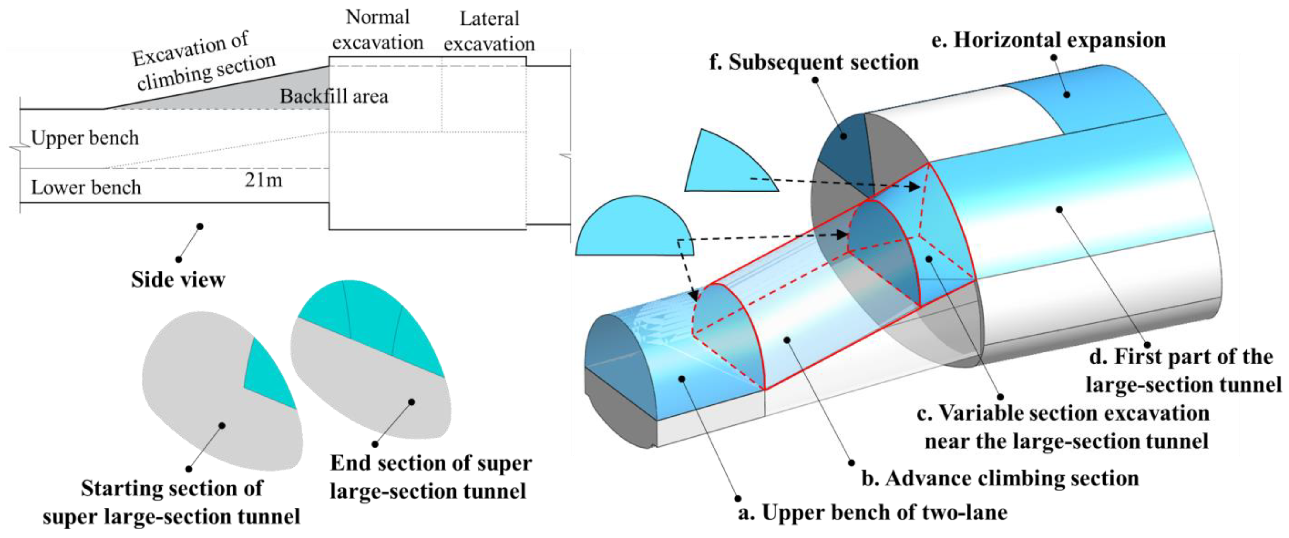
The starting point of inclined pilot tunnel is flexible. The slope is started in a reasonable location on the stepped section. Through analyzing the impact of the starting point on the stress of the surrounding rock and the backfill volume, the climbing angle is quantitatively calculated to ensure the stability of the surrounding rock. This method has broader applicability in similar projects.
(b)
The original excavation zoning scheme of a super-large cross-section tunnel will not change. Multi-stage excavation and the unloading of energy have an impact on the surrounding rock and support structures. Therefore, precise control of blasting technology is required for excavation. Synchronization of the support process is also crucial. After the completion of the climbing section excavation, the construction sequence of the large section is aligned with the design plan, ensuring the safety of tunnel construction.
(c)
Horizontal expansion will increase the number of workfaces, which is beneficial to improving the construction progress. After horizontal excavation, the subsequent construction processes can be easily connected, allowing for the addition of two to three working faces, effectively improving the progress of subsequent works.
In conclusion, there are fundamental differences between the two methods in terms of construction and support plans, construction progress, and control blasting technology. The RTM completes the section transition by constructing auxiliary IPT within the large section, with simple construction connections and lower requirements for section shape. However, the top heading process is more complex, and support operations cannot be carried out using the dual-side wall drift method. On the other hand, the ACM plans the starting point for climbing in advance and constructs the auxiliary IPTs outside the large section up to one side crown. The construction sequence of the two-lane section in the advance tunnel smoothly connects with the large section’s sequence, and subsequent excavation works in the large section can be carried out according to the design plan. To evaluate the stress and deformation patterns of the surrounding rock during the construction stages of the two methods, numerical simulation modeling and analysis are employed.

3. Numerical Simulation of Tunnel Excavation

Using the geotechnical finite element analysis software MIDAS GTS NX 2019, the initial stress model of the tunnel’s original rock is established based on the geological structure method [25]. According to the construction sequences of the two methods, three-dimensional computational models are created for the bifurcation tunnel’s variable-section construction stages. Considering the irregularity of the excavation face during the construction process, the support structure is simplified in the calculation process, focusing on analyzing the displacement and stress characteristics of the surrounding rock during the construction of the bifurcation tunnel.

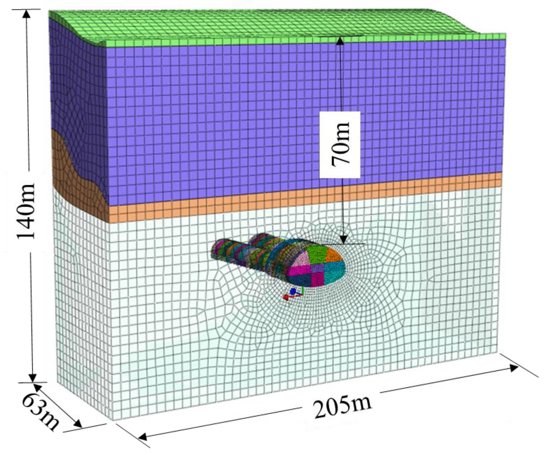
3.1. Computational Model and Material Parameters

The computational model is established based on the design parameters from the construction drawings. The transverse dimension is 205 m (greater than six times the tunnel diameter) to reduce boundary effects, and the longitudinal length is 63 m, corresponding to the engineering stationing from K1+838 to K1+901. The height is designed based on the actual depth, as shown in Figure 7. The model uses hexahedral solid elements for meshing. The mesh density is increased around the tunnel section by controlling the element size, with a minimum size of 0.5 m and a maximum size of 5 m. The boundary conditions of the rock mass are set with the ground surface as a free surface and the remaining boundaries as constrained boundaries. The load considered during calculations is the stress field due to self-weight. Using the software’s tunnel construction phase assistant, the excavation sequences for the bifurcation tunnel are designed with 3 m excavation progress per cycle. For the RTM, the computational model consists of 126 construction steps, and for the ACM, it consists of 119 construction steps. The models are shown in Figure 8a,b, respectively. The rock and soil materials in the computational model adopt the Mohr–Coulomb elastoplastic constitutive model. The material mechanical parameters are obtained from the engineering geological survey report, as shown in Table 1.

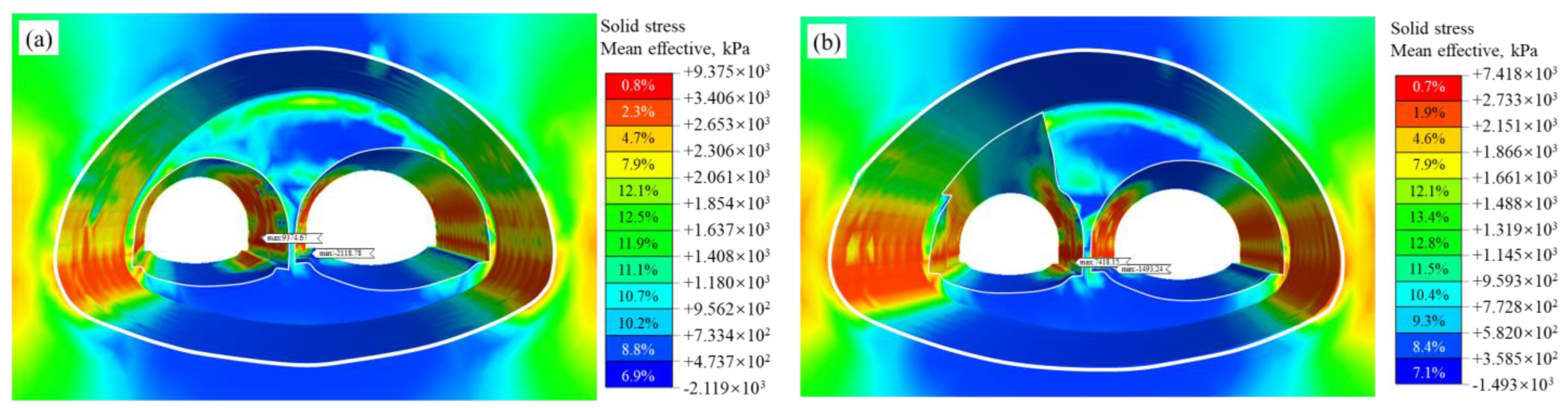
3.2. Analysis of Calculation Results

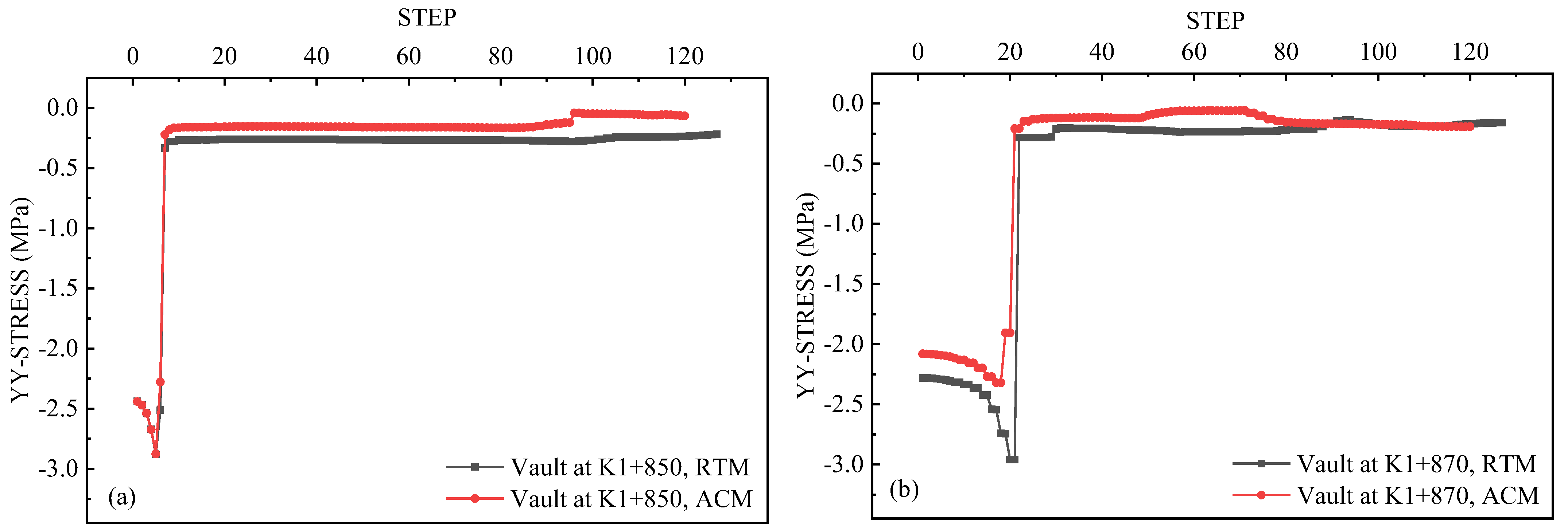
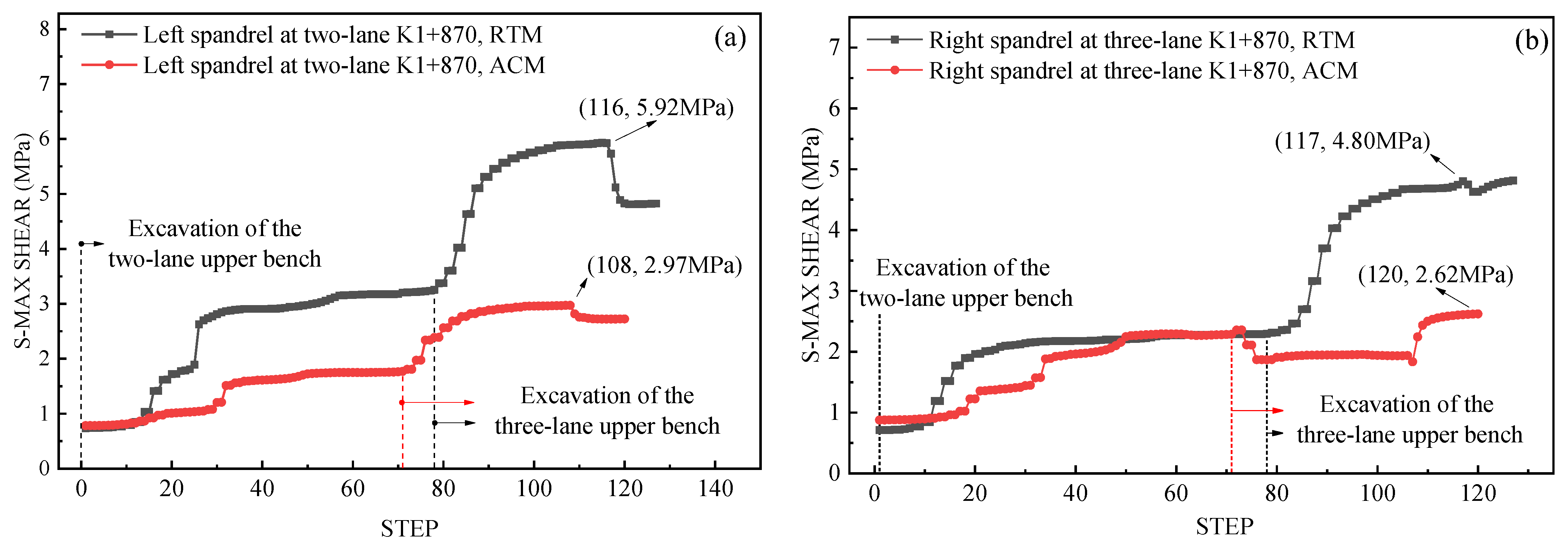
3.2.1. Force Characteristics of the Bifurcated Tunnel Envelope at Different Construction Steps

The contour plots of the average effective stress distribution in the surrounding rock during the construction stages of the bifurcation tunnel are shown in Figure 9. After excavation, the stress concentration in the five-lane tunnel is located in the arch waist areas on both sides. The small-clearance sections of the two-lane tunnel and the three-lane tunnel are concentrated in the arch shoulder and arch waist, especially in the arch shoulder area near the central rock. This pattern conforms to the stress distribution in the surrounding rock of the super-large-section tunnel. The surrounding rock of the five-lane section experiences compression at the top and bottom of the arch, while tension is observed on both sides of the arch waist. The maximum average effective stress is 9.38 MPa for the RTM and 7.42 MPa for the ACM. During the actual construction stage, it is important to strengthen the protection of the central rock and optimize the timing for the completion of excavation and support closure in the central drift of the five-lane section.
(1)
Analysis of the forces on the vault of the two-lane
Figure 10 shows the stress–time curves of the surrounding rock at the crown of the two-lane tunnel during the construction stages. As shown in Figure 10a, at the monitoring section K1+850 in the horizontal excavation segment, the crown stress is similar for both methods. At the monitoring section K1+870 in the climbing section (Figure 10b), the ACM starts constructing the IPT, with a peak vertical stress of 2.32 MPa in the surrounding rock. At this stage, the RTM is still in the stepped excavation of the two-lane tunnel, with the peak vertical stress in the surrounding rock remaining the same as in Figure 10a at 2.96 MPa, which is 1.3 times higher than the value of the ACM.
(2)
Analysis of the forces on the vault of the five-lane tunnel
Figure 11 depicts the stress–time curves of the crown in the horizontal and vertical directions at the monitoring section K1+890 of the five-lane section. With the increasing excavation steps of the five-lane super-large section, the stress redistribution in the surrounding rock occurs. The horizontal stress at the crown of the large section is in an unloading state. The main excavation steps that affect the redistribution of loads are the excavation of the initial drift and the first-layer excavation of the large section. The horizontal stress decreases gradually with the increase in excavation area until it reaches equilibrium. The final horizontal stress at the crown of the large section is 0.30 MPa for the ACM and 0.42 MPa for the RTM. The vertical stress increases and then decreases with the excavation steps, with the peak occurring during the excavation of the central drift in the first layer. The maximum vertical stress is 2.68 MPa for the ACM and 3.10 MPa for the RTM. In the stable state, the vertical stress in the surrounding rock for the ACM is 0.15 MPa, which is consistent with the results at the monitoring section K1+840. For the RTM, it is 0.46 MPa, approximately three times higher than the value for the ACM.
The stresses applied to the surrounding rock during the construction phase were greater for the RTM than for the ACM, the former being more demanding for the two-lane tunnel and the five-lane tunnel support structure.

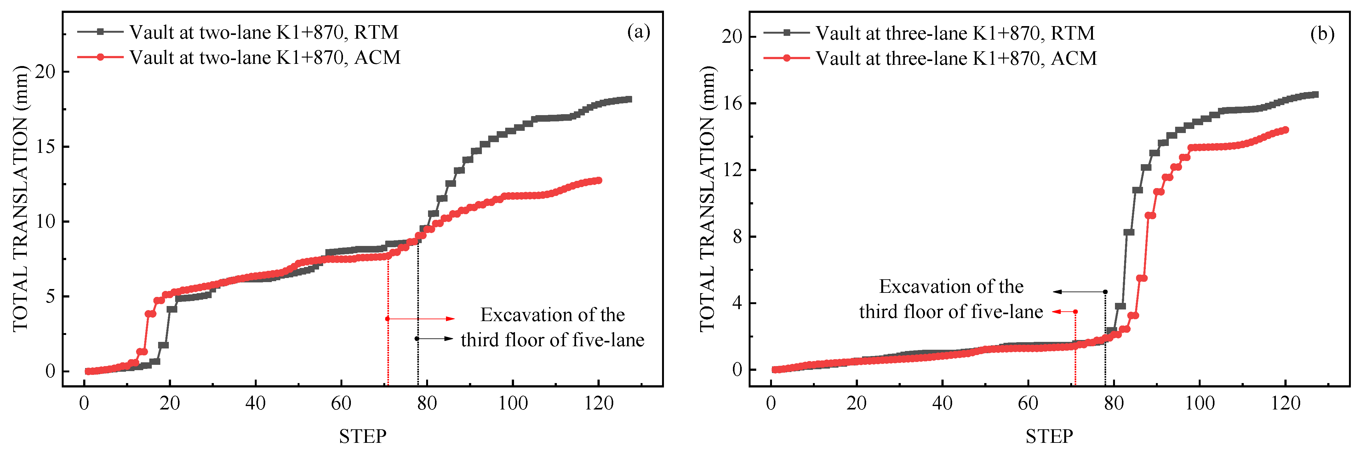
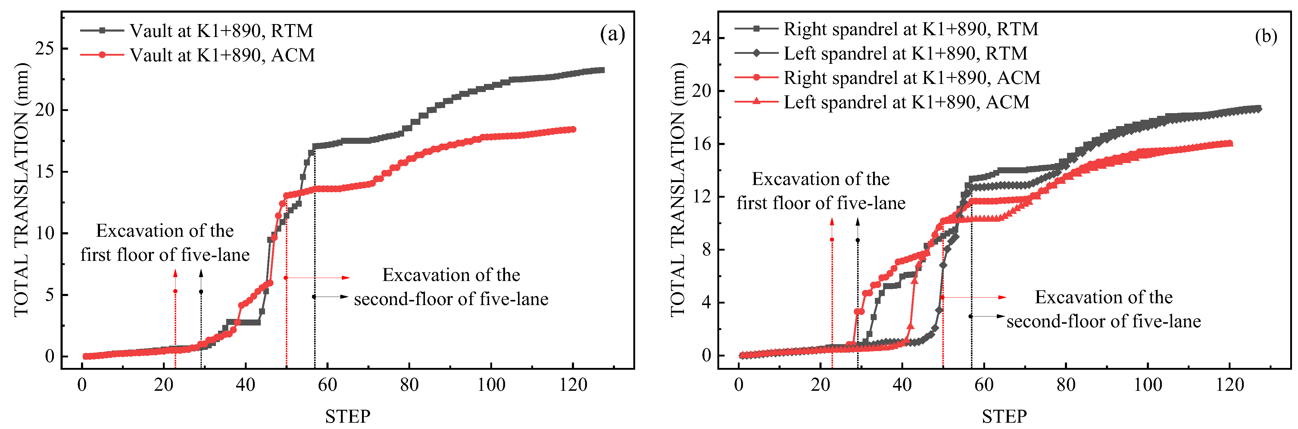
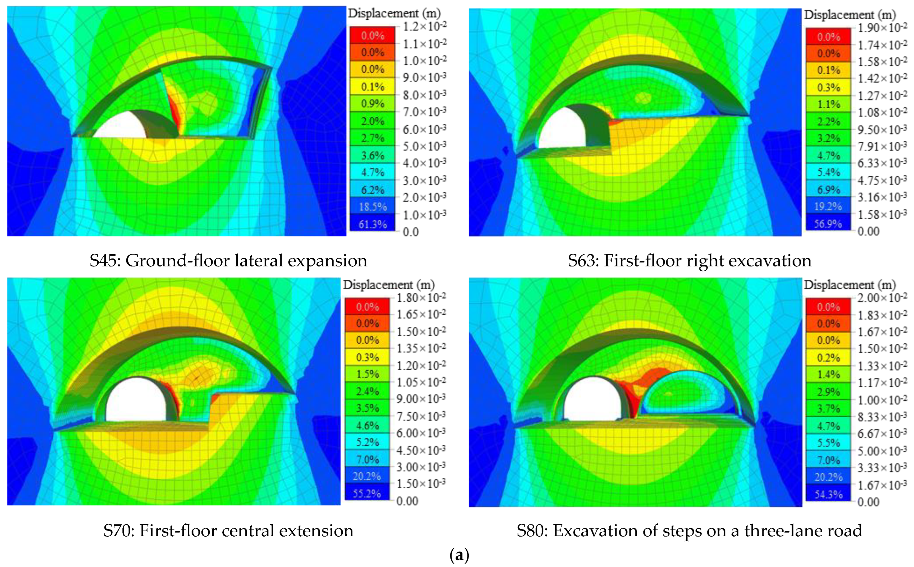
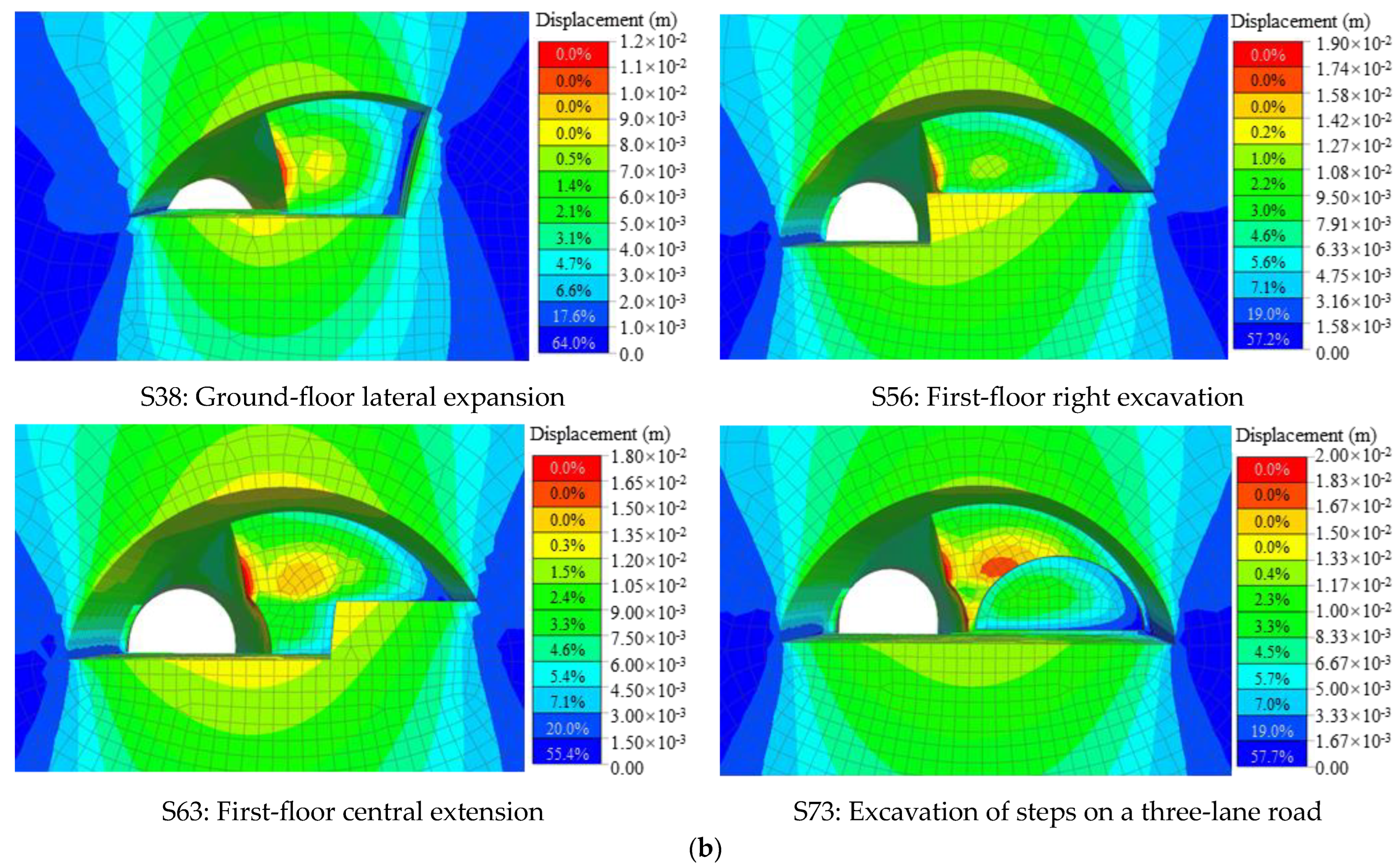
3.2.2. Deformation Patterns of the Bifurcated Tunnel Envelope at Different Construction Steps

From the perspective of stress in the surrounding rock during the construction stage, the RTM has higher requirements for the support structure of the two-lane tunnel and the five-lane section. The key monitoring sections for crown displacement near the bifurcation tunnel junction are shown in Figure 12 and Figure 13. From the figures, it can be observed that the excavation area of the five-lane section increases with the progress of excavation steps, and the differences in construction step sequences between the two methods result in different deformation patterns in the surrounding rock. As shown in Figure 12a,b, when the second-layer excavation of the large section is completed, the crown displacements of the two-lane tunnel and the three-lane tunnel increase rapidly. The growth rate is more pronounced in the RTM, with the maximum displacement at K1+870 in the two-lane tunnel being 1.4 times that of the ACM, and the peak displacement at the monitoring point K1+870 in the three-lane tunnel being 1.2 times that of the ACM. The displacement–time curves of the crown and shoulder of the large section at K1+890 are shown in Figure 13a,b, respectively. When the first-layer excavation of the large section starts, the crown and shoulder displacements increase rapidly. As the excavation steps progress and the displacement growth rate decreases, the displacements gradually reach equilibrium. It can be observed that the initial excavation unloading of the first layer of the large section has a significant impact on the stability of the surrounding rock. After excavation, the crown displacement of the RTM is 1.3 times that of the ACM, while the deformation is smaller in the ACM, indicating its superiority over the RTM.
Figure 14 presents the contour maps of the distributed rock mass displacement during the key steps of the large section (including the first-layer excavation of the large section, the second-layer excavation, and the stepping excavation of the three-lane tunnel). It visually demonstrates the changes in rock settlement influenced by the aforementioned factors. Compared to the RTM, the settlement of variable-section rock mass in the bifurcation tunnel is smaller in the ACM at each construction step.

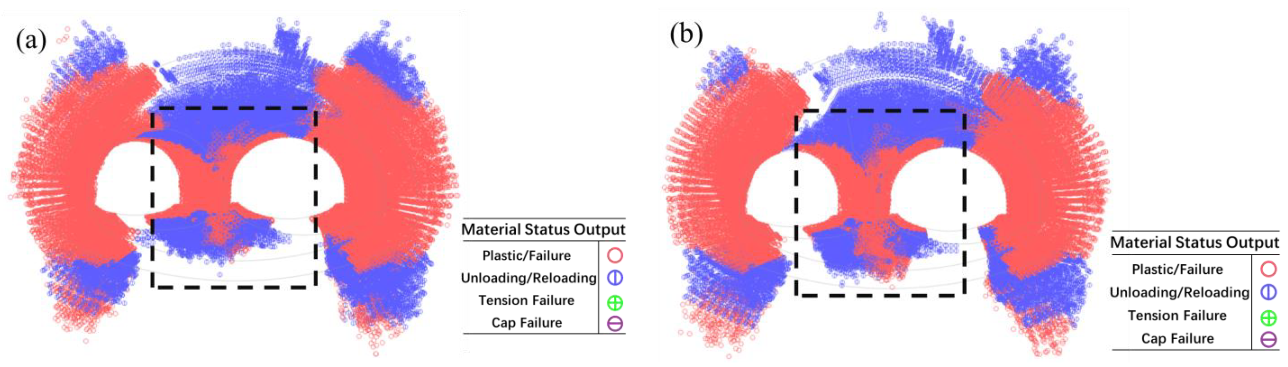
3.2.3. Distribution of Plastic Zones in Bifurcated Tunnels with Different Construction Steps

According to the Mohr–Coulomb strength criterion [26], when the shear stress at a certain point in the rock exceeds the shear strength, plastic deformation occurs and a plastic zone form. Generally, the shear strength of rocks is about 1/8 to 1/12 [27] of the compressive strength. The engineering exploration report of the Liantang tunnel indicates that the compressive strength of the slightly weathered sandstone in this section is 38.77 MPa, indicating a shear strength of approximately 3.23 to 4.84 MPa. The contour maps of the plastic zone distribution calculated for the two methods are shown in Figure 15. The red areas represent plastic failure disturbance zones, mainly concentrated in the central rock between the small-clearance tunnel sections and the arch waist area of the five-lane section. The disturbance zones caused by unloading during the construction process are distributed in the arch shoulder and arch waist areas of the surrounding rock. Notably, as shown in the dashed box in Figure 15, the RTM exhibits a significantly larger plastic failure disturbance zone at the bottom of the central rock pillar compared to the ACM.
The distribution of maximum shear stresses on both sides of the central rock is shown in Figure 16. The excavation of the two-lane tunnel and the three-lane tunnel are key construction steps affecting the stability of the central rock. At the monitoring point on the left shoulder of the advance tunnel (near the central rock), the maximum shear stress generated by the RTM is 5.92 MPa, while it is 2.97 MPa for the ACM. At the monitoring point on the right shoulder of the three-lane tunnel (near the central rock), the maximum shear stress for the RTM is 4.80 MPa, while it is 2.62 MPa for the ACM. Therefore, the shear stresses generated by the RTM exceed the plastic failure threshold of the rock, posing a safety hazard to the integrity and stability of the central rock.
In conclusion, through comparative analysis of the stress distribution, deformation, and plastic zone distribution patterns in the surrounding rock for the two construction methods, we found minimal differences in the rock unloading behavior between the two methods. The main distinctions lie in aspects such as construction duration, procedural rationality, and construction safety. Therefore, considering multiple influencing factors, we ultimately select a reasonable construction approach. The ACM is superior to the RTM and is suitable for the transitional construction of the Liantang bifurcation tunnel.

4. Monitoring and Measurement Results and Analysis of the Bifurcated Tunnel Construction Process

Figure 17 shows the excavation process of the variable-section transition construction using the ACM in the Liantang bifurcated tunnel. During the construction stage, the sinking of the crown, convergence of the surrounding clearance, and stress on the support structures are considered as the basic monitoring measurements [28], providing a basis for tunnel construction management and monitoring benchmarks.

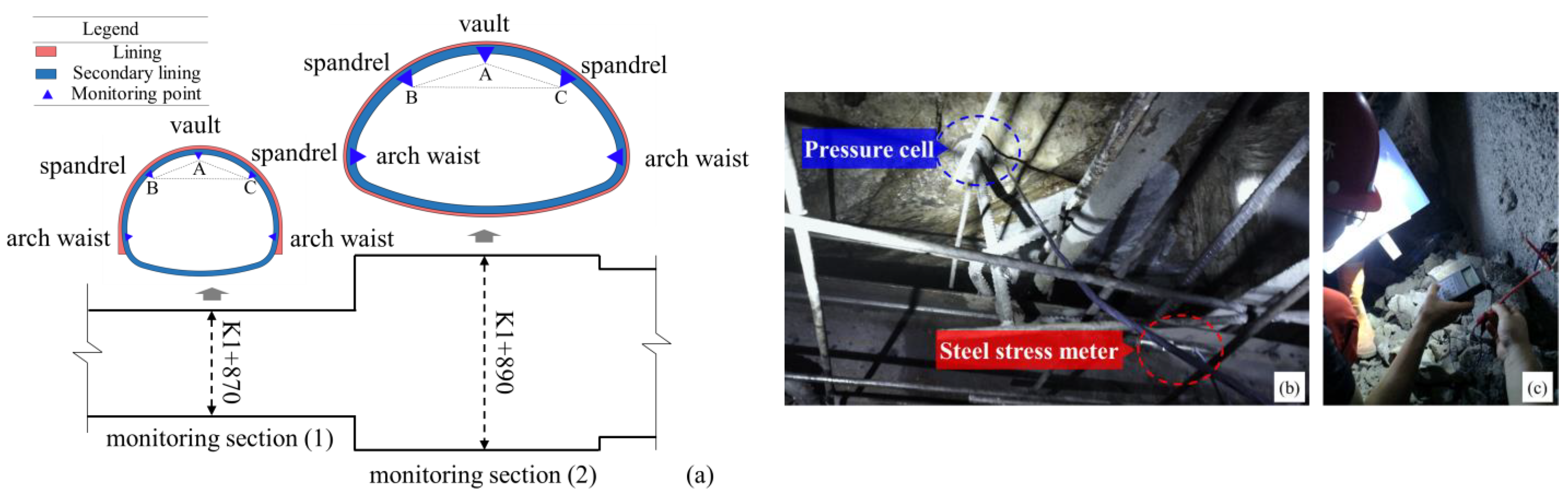
4.1. Monitoring and Measurement Scheme

Considering the characteristics and construction steps of the Liantang bifurcation tunnel, the deformation of the tunnel within the critical step intervals of the transition section is measured and monitored under the condition of satisfying the layout principles of monitoring sections. A monitoring section is set every 20 m, as shown in Figure 18a. Monitoring sections are set in the horizontal excavation section of the two-lane advance tunnel, the inclined heading section, and the super-large section. The monitoring points include crown displacement monitoring points and horizontal convergence monitoring points. In the support stage, the monitoring sensors are installed at the top, shoulder and waist of the monitoring section. Sensors include pressure cells and steel stress meter, as shown in Figure 15b. Figure 15b. Furthermore, Figure 15c shows the data collected on site.

4.2. Monitoring Results for the Two-Lane Section

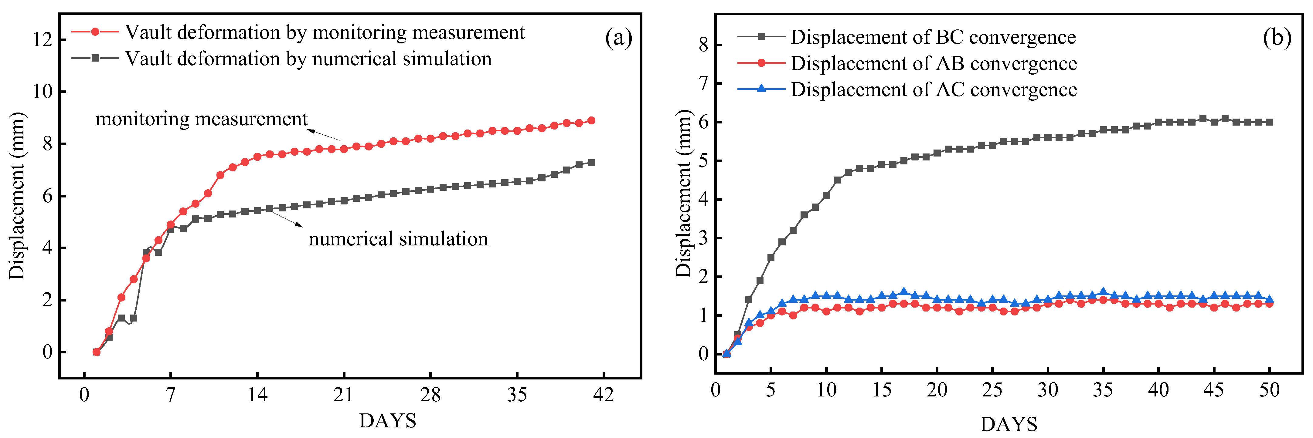
4.2.1. Changes in the Pattern of the Sinking of the Surrounding Rock Vault and Convergence around the Tunnel

The K1+870 monitoring section is located in the climbing section of the two-lane tunnel, 10 m away from the junction of the bifurcated tunnel. Monitoring started on 6 March 2018, as shown in Figure 19. Figure 19a indicates that the crown displacement at the K1+870 section initially exhibits a rapid increase in deformation with a deformation rate exceeding 1.0 mm/day. After three days of excavation, the crown displacement gradually increases. With the advancement of the secondary lining support structure, the convergence displacements are refined and reached a stable state after 15 days with a cumulative displacement of approximately 8.9 mm. The cumulative deformation of horizontal convergence around the tunnel is shown in Figure 19b. The convergence lines AB and AC show small convergence displacements, not exceeding 2 mm. The convergence displacement in the horizontal direction (BC) is larger, approximately 6.0 mm. The horizontal convergence displacement also shows a slow increase and gradually stabilizes.

4.2.2. Force Characteristics of the Surrounding Rock Support Structure

During the monitoring phase, pressure gauges are placed between the initial support and the secondary lining to measure the pressure data of the K1+870 section’s initial support and secondary lining in the two-lane tunnel. The pressure–time curves of the five monitoring points are shown in Figure 20. Since the filling concrete is used to form the profile of the two-lane tunnel above the climbing section, the peak pressure between the initial support and the secondary lining is located above the crown, reaching 0.58 MPa. The stabilizing time is about 7 days.

4.3. Construction Monitoring Results for the Five-Lane Section

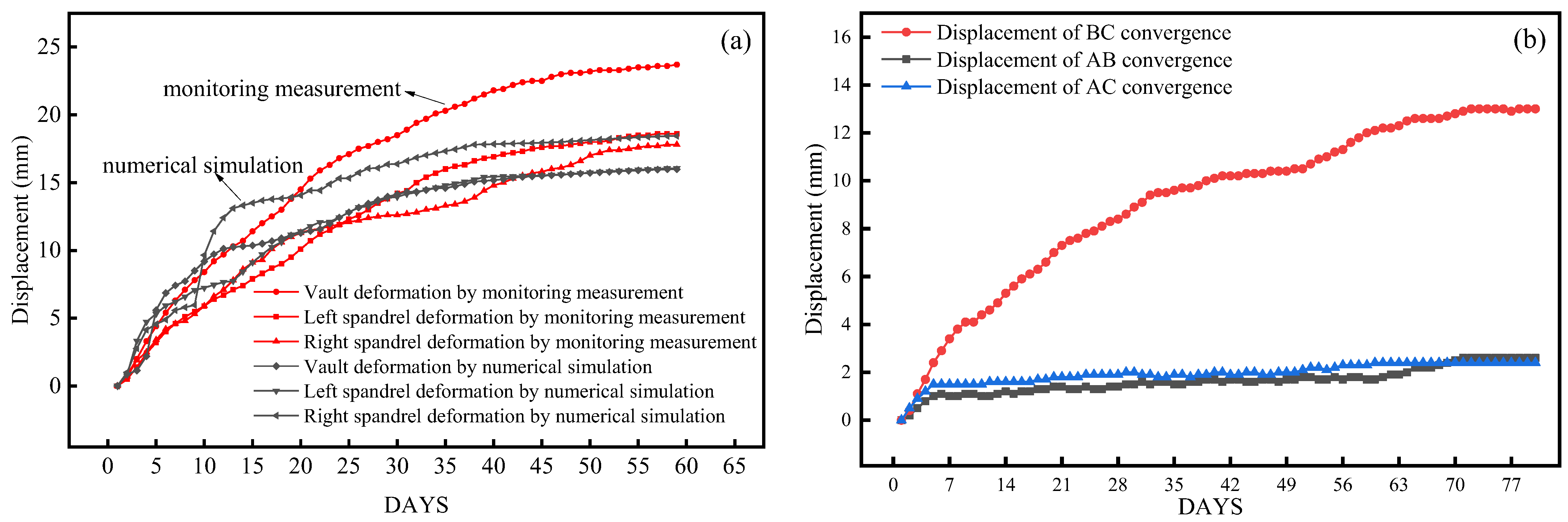
4.3.1. Changes in the Pattern of the Sinking of the Surrounding Rock Vault and Convergence around the Tunnel

After completing the first-layer reverse excavation, monitoring points are set at the crown and shoulder of the K1+890 monitoring section. The time–history curves of cumulative displacement with the progression of excavation steps are shown in Figure 21. The cumulative displacement of the large section increases continuously with the increase in the excavation area, reaching a maximum value of 23.7 mm. The maximum value of horizontal convergence around the tunnel is 13.0 mm, and the maximum rate of cumulative displacement change is 2.3 mm/day. It takes approximately 45 days to reach a stable state, which is three times that of the K1+870 monitoring section.

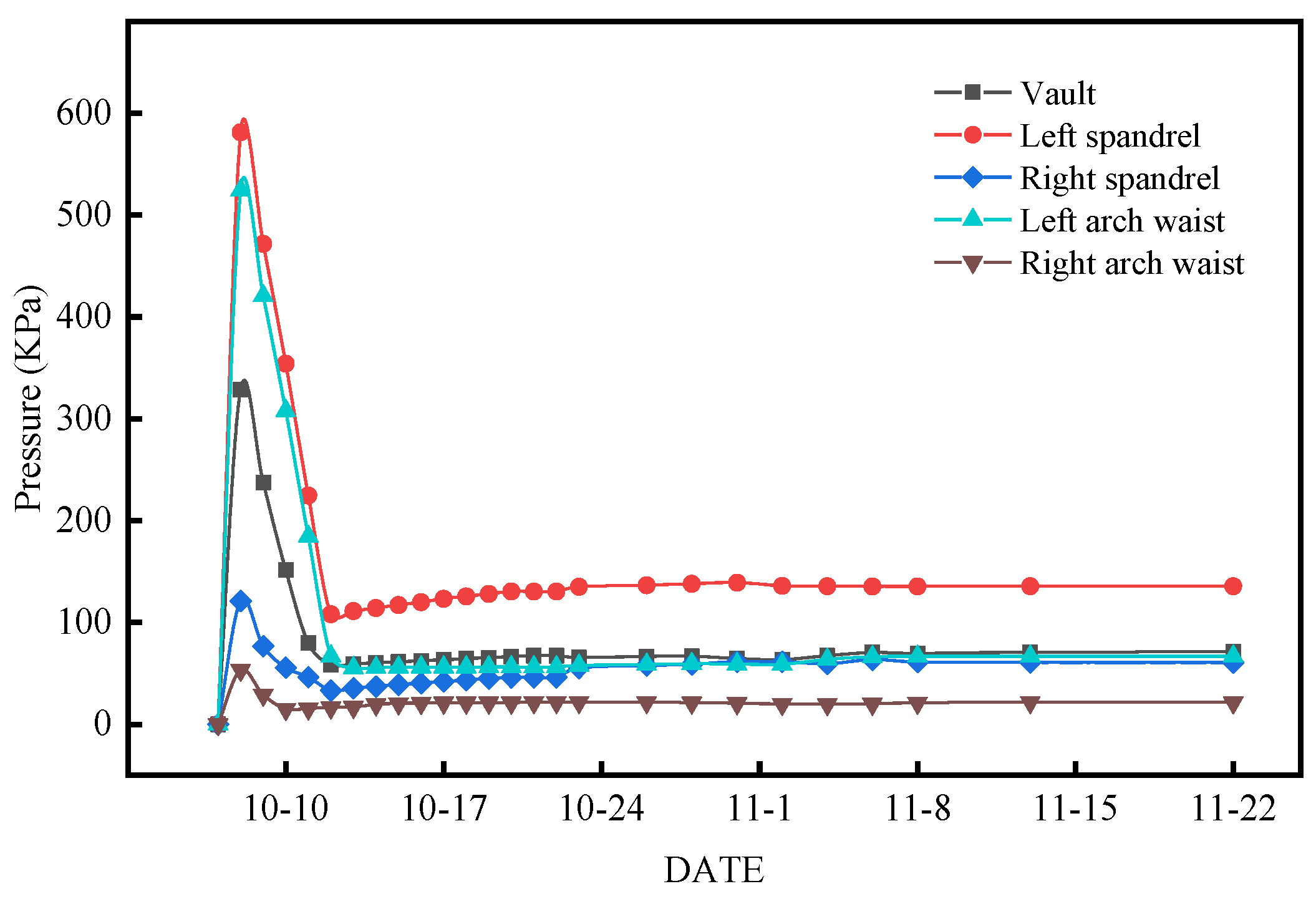
4.3.2. Force Characteristics of the Surrounding Rock Support Structure

The pressure–time curves of the initial support and secondary lining at the five monitoring points of the K1+890 monitoring section of the large section are shown in Figure 22. The results show that the maximum values of pressure in the initial support and secondary lining occur at the waist position, with a final maximum stable pressure value of 0.40 MPa. The stabilization time is approximately 14 days. Generally, the pressure at the waist monitoring point shows a trend of rapid increase followed by gradual development towards a stable value. The pressure at the shoulder monitoring point increases slowly before a rapid increase towards stabilization. However, the pressure at the crown monitoring point initially increases rapidly, then decreases after reaching a peak value and stabilizes. Therefore, it is necessary to strengthen the monitoring and assessment of the waist area after the completion of support.

4.4. Analysis and Evaluation of the Reasonableness of Construction Methods

The reasonableness of the construction of the large cross-section tunnel can be verified by determining whether the tunnel deformation is within the allowable range [29]. The allowable values for crown sinking and displacement span ratio in highway tunnels can be calculated using the Pusch formula and the French standards for crown sinking. The formula for calculating the allowable crown sinking value δ is as follows:
δ = 12 b 0 f 1.5 ,
where f and b0 denote Pratt’s coefficient and the cavity span, respectively.
Table 2 lists the maximum crown sinking displacement and allowable values at the monitoring sections of the Liantang bifurcation tunnel. The statistical analysis shows that both the crown sinking and convergence displacement results are smaller than the allowable displacements and are within the safe allowable range. The monitoring data validates the rationality of the tunnel construction method.

5. Conclusions

(1)
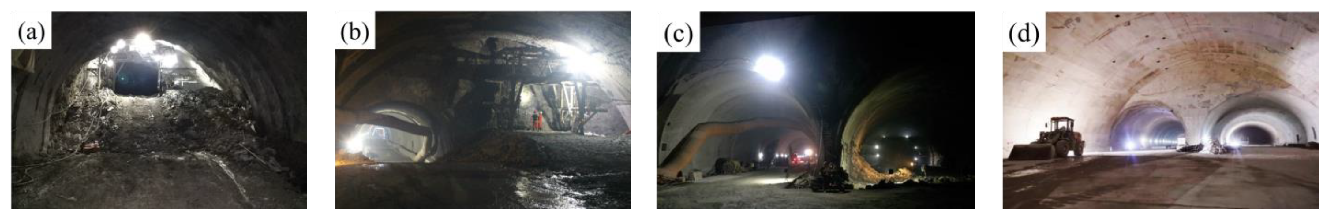
Taking the bifurcated section of the Liantang Tunnel, the largest cross-section highway tunnel currently, as the research object, two excavation schemes for transitioning from a small cross-section to a large cross-section tunnel were proposed. Numerical simulation was used to analyze the stress and deformation characteristics of the surrounding rock during the excavation process in the bifurcation section, and on-site verification was conducted. The calculation results provide a theoretical basis for the design of the transitional excavation scheme, optimization of excavation steps, and support recommendations. They are of significant reference value for the future formulation of design specifications for super-large cross-sections with more than four lanes.
(2)
A three-dimensional computational model for the excavation of a large cross-section bifurcation tunnel was established using the MIDAS GTS NX software, and the calculation results of the two schemes were analyzed. During the construction process, the total displacement of the crown in the large section and the small-clearance section in the RTM was 1.2 to 1.4 times that of the ACM. After construction stabilization, the vertical stress at the crown in the ACM was approximately three times that of the RTM. During the excavation of the large section, the maximum shear stress of the intermediate rock in the RTM exceeded the plastic failure threshold of 5.92 MPa for rock, while the ACM remained within the safe range. The calculation results indicate that the ACM is the optimal excavation scheme.
(3)
The on-site monitoring results of the Liantang tunnel show that after adopting the ACM, the large section was excavated using the double sidewall method. The maximum cumulative displacement in the large-section tunnel was 23.7 mm, and for the two lanes, it was 8.5 mm. The peak pressures of the initial support and secondary lining were concentrated in the waist areas on both sides, reaching 0.4 MPa for the large section and 0.58 MPa for the two lanes, located near the shoulder and waist areas close to the intermediate rock. The crown sinking and convergence displacements of the surrounding rock in the Liantang bifurcated tunnel were within the allowable displacement safety range for highway tunnels, confirming the rationality of the ACM.

Author Contributions

Conceptualization, X.W.; methodology, X.W. and Y.L.; software, Y.W.; validation, H.W.; formal analysis, M.G.; investigation, H.W.; resources, M.G.; data curation, Y.W.; writing—original draft preparation, X.W.; writing—review and editing, Y.L. and H.W.; visualization, X.W. and Y.L.; supervision, M.G.; project administration, M.G.; funding acquisition, M.G. and X.W. All authors have read and agreed to the published version of the manuscript.

Funding

This research was funded by the National Natural Science Foundation of China, grant number 51934001 and the China Postdoctoral Science Foundation, grant number 2022TQ0025.

Institutional Review Board Statement

Not applicable.

Informed Consent Statement

Not applicable.

Data Availability Statement

The data used to support the findings of this study are available from the corresponding author upon request. The data are not publicly available due to personal information and privacy about the data.

Acknowledgments

We would like to acknowledge the editors and reviewers for their invaluable comments.

Conflicts of Interest

The authors declare that they have no known competing financial interest or personal relationships that could have appeared to influence the work reported in this paper.

References

  1. Zhang, J.; Wu, J.; Yan, C.; Gou, X.; Ye, L.; Feng, J. Construction technology of super-large section of highway tunnels with four or more lanes in China. China J. Highw. Transp. 2020, 33, 14–31. [Google Scholar] [CrossRef]
  2. Hong, K.; Feng, H. Development trends and views of highway tunnels in China over the past decade. China J. Highw. Transp. 2020, 33, 62–76. [Google Scholar] [CrossRef]
  3. Zhang, J.; Li, S.; Li, L.; Zhang, Q.; Xu, Z.; Xu, Z.; Wu, J.; He, P. Grouting effects evaluation of water-rich faults and its engineering application in Qingdao Jiaozhou Bay Subsea Tunnel, China. Geomech. Eng. 2017, 12, 35–52. [Google Scholar] [CrossRef]
  4. Zhang, J.; Xu, J.; Gong, Y.; Xu, X.; Zhang, H.; Ye, L. Study on construction method optimization and construction mechanical characteristics of a single-span five-lane highway tunnel. Tunn. Constr. 2021, 41, 831–840. [Google Scholar] [CrossRef]
  5. Zhang, H.; Wang, S.; Zhou, D. Stability analysis of bifurcated highway tunnels with large section in tiger leaping gorge. Highway 2021, 66, 342–346. [Google Scholar]
  6. Barla, G. Full-face excavation of large tunnels in difficult conditions. J. Rock Mech. Geotech. Eng. 2016, 8, 294–303. [Google Scholar] [CrossRef]
  7. Rehman, H.; Naji, A.M.; Ali, W.; Junaid, M.; Abdullah, R.A.; Yoo, H.-K. Numerical evaluation of new Austrian tunneling method excavation sequences: A case study. Int. J. Min. Sci. Technol. 2020, 30, 381–386. [Google Scholar] [CrossRef]
  8. Zhou, Z.; Zhao, J.; Tan, Z.; Zhou, X. Mechanical responses in the construction process of super-large cross-section tunnel: A case study of Gongbei tunnel. Tunn. Undergr. Space Technol. 2021, 115, 104044. [Google Scholar] [CrossRef]
  9. Cao, Z.; Xie, Q.; Song, Z.; Wang, J. Effect of unloading on surrounding rock pressure of super large-section tunnel. Chin. J. Rock Mech. Eng. 2020, 39 (Suppl. S1), 2882–2891. [Google Scholar] [CrossRef]
  10. Luo, Y.; Chen, J.; Gao, S.; Deng, X.; Diao, P. Stability analysis of super-large-section tunnel in loess ground considering water infiltration caused by irrigation. Environ. Earth Sci. 2017, 76, 763. [Google Scholar] [CrossRef]
  11. Tu, H.; Zhou, H.; Qiao, C.; Gao, Y. Excavation and kinematic analysis of a shallow large-span tunnel in an up-soft/low-hard rock stratum. Tunn. Undergr. Space Technol. 2020, 97, 103245. [Google Scholar] [CrossRef]
  12. Qiu, W.; Sun, K.; Wang, L.; Ma, M.; He, Y.; Chen, J.; Wen, Z.; Wang, G. Primary support optimization of large section tunnel based on surrounding rock stability. China Civ. Eng. J. 2017, 50 (Suppl. S2), 8–13. [Google Scholar]
  13. Zhang, W.; Qi, J.; Zhang, G.; Niu, R.; Zhang, C.; He, L.; Lyu, J. Full-scale experimental study on failure characteristics of the key segment in shield tunnel with super-large cross-section. Tunn. Undergr. Space Technol. 2022, 129, 104671. [Google Scholar] [CrossRef]
  14. Hu, Y. Research on bi-directional construction technology for super-closely-spaced bifurcated tunnel with long span. Railw. Constr. Technol. 2018, 12, 77–80. [Google Scholar]
  15. Yan, Z.; Zhang, L.; Lu, J.; Zou, J. Study on Construction Method of the Intersection of the Urban Underground Interchange Tunnel. Mod. Tunn. Technol. 2019, 56, 176–184. [Google Scholar] [CrossRef]
  16. Zhang, F.; Lei, S.; Yang, R.; Shi, L.; Sun, W.; Qiao, Q. Numerical simulation of the construction of forked tunnels with super small spacing. China Sci. Pap. 2019, 14, 157–163. [Google Scholar]
  17. Liu, C.; Peng, Z.; Cui, J.; Huang, X.; Li, Y.; Chen, W. Development of crack and damage in shield tunnel lining under seismic loading: Refined 3D finite element modeling and analyses. Thin-Walled Struct. 2023, 185, 110647. [Google Scholar] [CrossRef]
  18. Hu, D.; Li, Y.; Yang, X.; Liang, X.; Zhang, K.; Liang, X. Experiment and Application of NATM Tunnel Deformation Monitoring Based on 3D Laser Scanning. Struct. Control. Health Monit. 2023, 2023, 3341788. [Google Scholar] [CrossRef]
  19. Ji, L.; Zhou, C.; Lu, S.; Jiang, N.; Li, H. Modeling study of cumulative damage effects and safety criterion of surrounding rock under multiple full-face blasting of a large cross-section tunnel. Int. J. Rock Mech. Min. Sci. 2021, 147, 104882. [Google Scholar] [CrossRef]
  20. Gao, Y.; Xu, F.; Zhang, Q.; He, P.; Qin, Z. Geotechnical monitoring and analyses on the stability and health of a large cross-section railway tunnel constructed in a seismic area. Measurement 2018, 122, 620–629. [Google Scholar] [CrossRef]
  21. Zhang, H.; Zhang, G.; Pan, Y.; Hao, Z.; Chen, S.; Cheng, F. Experimental study on the mechanical behavior and deformation characteristics of lining structure of super-large section tunnels with a small clearance. Eng. Fail. Anal. 2022, 136, 106186. [Google Scholar] [CrossRef]
  22. Yu, J.; Zhu, Y.; Yao, W.; Liu, X.; Ren, C.; Cai, Y.; Tang, X. Stress relaxation behaviour of marble under cyclic weak disturbance and confining pressures. Measurement 2021, 182, 109777. [Google Scholar] [CrossRef]
  23. Zhao, J.; Tan, Z.; Yu, R.; Li, Z.; Wang, X. Mechanical responses of a shallow-buried super-large-section tunnel in weak surrounding rock: A case study in Guizhou. Tunn. Undergr. Space Technol. 2023, 131, 104850. [Google Scholar] [CrossRef]
  24. Jiang, S.; Lin, Z.; Wang, S. China’s road tunnel development in 2018. Tunn. Constr. 2019, 39, 1217. [Google Scholar]
  25. Liu, J.; Lu, Z.; Zhang, W.; Zhang, L. Research on the Structure Design for Four-tracked-double Station Tunnel in Steep Dip Stratum. J. Railw. Eng. Soc. 2016, 33, 113–117. [Google Scholar] [CrossRef]
  26. Zhang, G.; Zhang, Y. Partition failure characteristic of rock material loading and unloading based on Mohr-Coulomb criterion. J. China Coal Soc. 2019, 44, 1049–1058. [Google Scholar] [CrossRef]
  27. Zheng, L. Research on Quantitative Three-dimensional Description of Rough Surface and the Correlation between Shear Strength and Parameter. Master’s Thesis, Chengdu University of Technology, Chengdu, China, 2017. [Google Scholar]
  28. Jiang, K.; Xia, C. Analysis of monitoring and measurement of small clear spacing highway tunnel with eight lanes. Chin. J. Rock Mech. Eng. 2010, 29 (Suppl. S2), 3755. [Google Scholar]
  29. Zhou, D.; Cao, L.; Qu, H.; Yi, L.; Fang, S. Deformation monitoring and control of super large section highway tunnel with different surrounding rocks. Chin. J. Rock Mech. Eng. 2009, 28, 2510–2519. [Google Scholar] [CrossRef]
Figure 1. Geographical position of Liantang Tunnel.
Applsci 13 12852 g001
Figure 2. Bifurcation section of Liantang Tunnel: (a) the plan view, (b) the section structure.
Applsci 13 12852 g002
Figure 3. Longitudinal section of the main line of the Liantang tunnel.
Applsci 13 12852 g003
Figure 4. Construction methods for different sections of bifurcated tunnels (unit: m).
Applsci 13 12852 g004
Figure 5. Construction steps of the RTM.
Applsci 13 12852 g005
Figure 6. Construction steps of the ACM.
Applsci 13 12852 g006
Figure 7. Computational model and grid division.
Applsci 13 12852 g007
Figure 8. Meshing of excavated rock during construction: (a) the model of RTM, (b) the model of ACM.
Applsci 13 12852 g008
Figure 9. Cloud map of the effective stress distribution in the surrounding rock: (a) RTM, (b) ACM.
Applsci 13 12852 g009
Figure 10. Stress curve of two-lane surrounding rock vault: (a) at K1+850, (b) at K1+870.
Applsci 13 12852 g010
Figure 11. Stress curve of five-lane surrounding rock vault: (a) horizontal stress; (b) vertical stress.
Applsci 13 12852 g011
Figure 12. Curve of vault displacement with excavation steps: (a) two-lane, (b) three-lane.
Applsci 13 12852 g012
Figure 13. Curve of displacement with excavation steps: (a) vault of five-lane, (b) spandrel of five-lane.
Applsci 13 12852 g013
Figure 14. Cloud map of surrounding rock displacement during the construction of the five-lane key step sequence: (a) RTM, (b) ACM.
Applsci 13 12852 g014aApplsci 13 12852 g014b
Figure 15. Cloud map of the plastic area. (a) RTM, (b) ACM.
Applsci 13 12852 g015
Figure 16. Curve of the maximum shear stress of the measuring points on both sides of the interlaid rock during the construction of the bifurcated tunnel: (a) at two-lane K1+870, (b) at three-lane K1+870.
Applsci 13 12852 g016
Figure 17. Site construction photos of bifurcated tunnel: (a) excavation of inclined tunnel, (b) reverse excavation of three-lane tunnel, (c) excavation of three-lane tunnel, (d) picture of the bifurcated tunnel.
Applsci 13 12852 g017
Figure 18. Plan for monitoring and measurement: (a) pattern of the monitoring section and monitoring point of bifurcated tunnel; (b) install monitoring sensors; (c) collect data.
Applsci 13 12852 g018
Figure 19. Curve of displacement and displacement change rate of surrounding rock at two-lane K1+870: (a) vault; (b) horizontal convergence around the tunnel.
Applsci 13 12852 g019
Figure 20. Pressure–time history curve between the initial support and the second lining at two-lane K1+870.
Applsci 13 12852 g020
Figure 21. Curve of displacement and displacement change rate of surrounding rock at five-lane K1+890: (a) vault; (b) horizontal convergence around the tunnel.
Applsci 13 12852 g021
Figure 22. Pressure–time history curve between the initial support and the second lining at five-lane K1+890.
Applsci 13 12852 g022
Table 1. Material parameters in the model.
Rock FormationBulk Density (kN·m−3)Elastic Modulus (GPa)Poisson’s RatioCohesion
(kN·m−2)
Internal Friction Angle (°)
silty clay19.00.60.426.525
slightly weathered sandstone23.06.00.350033
slightly weathered rhyolite25.012.00.2790045
Table 2. Statistical analysis of extremum and admissible value of settlement.
Excavate SectionMonitoring SectionCumulative
Displacement/mm
Ratio of
Displacement to Span/%
Allowable
Displacement/mm
Robustness
Factor (f)
two-lane tunnelK1+8708.50.06718.094.14
five-lane tunnelK1+89023.70.09142.744.14
Disclaimer/Publisher’s Note: The statements, opinions and data contained in all publications are solely those of the individual author(s) and contributor(s) and not of MDPI and/or the editor(s). MDPI and/or the editor(s) disclaim responsibility for any injury to people or property resulting from any ideas, methods, instructions or products referred to in the content.

