Article

Supporting Structure of Steel Corrugated Plate-Mold Bag Concrete and Its Application in a Circular Shaft

Key Laboratory of Urban Security and Disaster Engineering, Ministry of Education, Beijing University of Technology, Beijing 100124, China
*
Author to whom correspondence should be addressed.
Appl. Sci. 2023, 13(23), 12937; https://doi.org/10.3390/app132312937
Submission received: 20 September 2023 / Revised: 10 November 2023 / Accepted: 11 November 2023 / Published: 4 December 2023
(This article belongs to the Special Issue Urban Underground Engineering: Excavation, Monitoring, and Control)

Abstract

:
To cater to the problems of a poor working environment, a large amount of rebound, and the high energy consumption of sprayed concrete in tunnel engineering, this paper proposes a new support scheme with a steel corrugated plate combined with mold bag concrete. Analytical solutions of stresses for steel corrugated plate and mold bag concrete were deduced based on the thin-walled cylinder, and then their strength safety factors were presented. Subsequently, a series of numerical simulations were conducted to investigate the mechanical performance of the third ring of the main structure based on the ‘load-structure’ 3D model. The numerical results were verified using the classical theoretical analysis and the proposed model, and then parametric studies were performed through the numerical method. Finally, field tests in a circular shaft were carried out to verify the feasibility of the structure and process and the engineering effect. The results show that the combination of steel corrugated plate and mold bag concrete is feasible and can realize rapid support technology for underground engineering, which provides a new idea for the supporting technology of underground engineering such as tunnels.

1. Introduction

Nowadays, traditional primary support, mainly made of sprayed concrete and steel frame, has been widely used in underground engineering such as foundation pits and tunnels. It is applied through a process by which concrete or mortar is sprayed onto a surface to produce a compacted, self-supporting, and load-bearing layer [1]. Although traditional support is highly mature, it still has lots of drawbacks as well. Firstly, concrete is a kind of brittle material and can hardly bear any tensile stress. Secondly, problems such as large dust, high rebound rate, and poor quality stability are common during the construction of sprayed concrete [2]. In particular, a high rebound rate will not only cause quality defects due to the too-thin thickness of sprayed concrete but also waste material resources and increase construction costs.
In order to solve the above problems, some scholars have proposed a steel corrugated plate as the main body of the support structure [3,4]. Firstly, as a kind of construction material, steel is very popular in civil engineering, and has been studied in great depth for its composition and properties [3,5]. Secondly, the mechanical analysis of steel-concrete composite structures is a hot topic in civil engineering research as well [6,7,8]. Corrugated steel structures are favored by engineers because of their advantages, such as high strength, easy maintenance, convenience of the construction process, and environmentally friendliness. For example, the mechanical properties of corrugated steel plate shear walls under cyclic loading were investigated [9]. Besides, the performance of corrugated steel supports under seismic loads was also studied [10,11]. Then, in view of the characteristic that steel is liable to get rusty, related research on anticorrosive corrugated steel has been carried out [12,13,14]. However, how to ensure that the steel corrugated plate structure maintains close contact with the excavation surface and reduces voids is the main challenge affecting its popularization and application in underground engineering.
In response, this paper proposes using mold bag concrete to fill the void between the corrugated steel plate and the excavation face. In recent years, geosynthetics such as geotextiles have gradually been used in various fields of civil engineering, such as structural seismic, material reinforcement, and new building materials [15,16,17,18]. Among them, a mold bag is one of the geosynthetics, which is a double-layer bag-like fabric woven by a machine from high-strength chemical fiber filaments with engineering characteristics of permeability, air permeability, and impermeability to slurry [19]. Therefore, the mold bag concrete relies on this characteristic of the mold bag, relying on self-weight and the pressure of the grout pump to discharge excess water from the pores of the mold bag, which reduces the water-cement ratio and achieves the design strength after solidification [20,21]. In China, mold bag concrete is widely used in canal and slope protection engineering because of its unique advantages. As fabric can only be loaded with tensile stress, fabric pretension is essential, and Veenendaal and Block [22] constructed two prototype shell structures based on numerical modeling to control the prestress applied to the fabric. Foster and Ibell [23] proposed a new numerical method for determining the shape of flexible, impermeable, and inextensible suspended fabric sections affected by hydrostatic loads imposed by wet concrete. Moreover, Ghaib and Gorski [20] obtained the relationship between the compressive strength of molded concrete and the mechanical parameters of the formwork and concrete based on destructive tests on concrete specimens molded in different fabrics. In summary, there are two main advantages to using fabric formwork in general. Firstly, it saves energy and reduces greenhouse gas emissions, making for more sustainable designs. Secondly, the permeability of the fabric will affect the quality of the concrete surface, reducing the number of air voids and blowholes and therefore improving overall durability [24,25]. However, there has been no more in-depth research on the composition and properties of mold bag concrete to date.
In addition, with the development of information technology, intellectualization has been gradually applied to the field of civil engineering. There are many cases of using artificial intelligence algorithms as well as deep-learning-based algorithms to solve engineering problems, especially in structural engineering and structural mechanics. For example, Deng et al. [26] proposed an AI-based FE model update to determine equivalent stationary dynamic loads for moving loads by comparing and analyzing two fundamental AI algorithms and their improved algorithms, namely genetic algorithm (GA) and particle swarm optimization (PSO). Liu [27] introduced a genetic algorithm (GA) and combined covariance-Gaussian process regression (CCGPR) coupling algorithm (GA-CCGPR) for information-based construction in tunneling engineering and proposed an optimization method for the preliminary support parameters based on it. Besides, Nadeem et al. [28] proposed a deep learning-based research method for damage identification for underground metro shield tunnels by utilizing an existing deep auto-encoder (DAE) that can support deep neural networks. Shi et al. [29] used the support vector machine (SVM) information granulation method to predict the surrounding rock deformation. Therefore, the use of some deep-learning-based algorithms to study the overall behavior of the structure is of great benefit, and it can be seen that these intelligent techniques are promising for future engineering applications.
But so far, there is no combination of steel corrugated plate and mold bag concrete for use in the supporting structure of tunnels or foundation pits worldwide. Therefore, to study its mechanical characteristics, this paper has built finite element models and verified their correctness using theoretical analysis. On this basis, the structure and material parameters of the steel corrugated plate and mold bag were designed based on the circular shaft, and field tests using the inverted hanging shaft wall reverse construction method were carried out to verify the feasibility of the structure and process and the engineering effect. Under the action of filling pressure, the mold bag concrete forms a convex-concave random shape with the shape of the excavation surface and the corrugated steel plate, which can densely fill the structural gap between the excavation surface and the corrugated steel plate and ensure that there is no leakage of the slurry. This innovative supporting structure will effectively solve the problems of poor working environment, high energy consumption, slurry running, and leakage during the construction of sprayed concrete, which provides new ideas for the support technology of tunnels and other underground engineering.

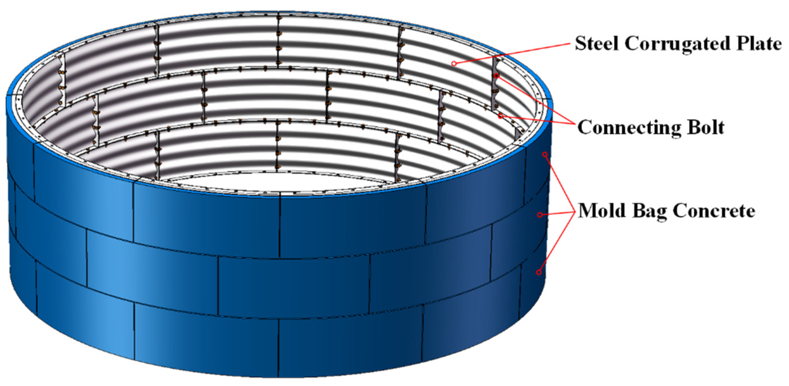
2. Composition and Structure of Steel Corrugated Plate-Mold Bag Concrete

The steel corrugated plate-mold bag concrete supporting structure is mainly composed of three parts: the steel corrugated plate segment, the mold bag, and the concrete poured on-site in the mold bag. The steel corrugated plate segment and the mold bag are customized by the factory, and the fine stone concrete in the mold bag is poured under pressure on-site using a small high-pressure concrete pump. This paper takes the circular shaft support structure in underground engineering as an example, draws on the division form and assembly method of shield tunnel segments, and uses longitudinal staggered joints to assemble each part (shown in Figure 1).

2.1. Steel Corrugated Plate Member

The steel corrugated plate segment is welded using a steel corrugated panel, two end flange plates, and two side flange plates. One lead hole for the concrete pouring pipe and one lead hole for the pressure control pipe is reserved on the steel corrugated panel (shown in Figure 2). The adjacent segments are connected by the end flange plate and the side flange plate along their respective lengths, with reserved bolt holes for circumferential and longitudinal positioning connections. The height H of the steel corrugated plate member can be determined according to the excavation footage, and the width B of the end flange plate needs to meet the bolt connection requirements. The arc length L of the side flange plate is determined comprehensively according to the inner diameter of the supporting structure, the number of annular joints, the self-weight of the steel corrugated plate, and the ease of assembly and operation.

2.2. Mold Bag and Mold Bag Concrete

The mold bag is a geosynthetic material, which is a double-layer bag-like fabric woven with high-strength fiber filaments. It has the engineering properties of water being permeable, breathable, impermeable, and having fast drainage and consolidation speeds. In this paper, the mold bag is sewn from a rectangular side seal formed by folding it in half and two strip end seals, and a concrete pouring pipe and a pressure control pipe are set on one side of the steel corrugated panel (shown in Figure 3a). The mold bag length L’ is the same as the arc length L of the steel corrugated panel, and the height H’ is consistent with the total arc length of the corrugated panel along the height direction. The thickness of the mold bag t is selected according to the stiffness requirements of the support structure and the combined mechanical performance of the steel corrugated plate. It can also refer to the design parameters of the initial support thickness in the existing design specifications for sprayed concrete. The material of the mold bag should comprehensively consider its cost, tensile properties, and water permeability, and polyester filament geotextile should be selected.
The concrete is pumped into the mold bag using the pressurized pump and is constrained with the mold bag to be wrapped and formed in the construction void. Under the action of pouring pressure, part of the gas and water in the concrete in the mold bag is squeezed out, so that the voids are reduced, the water-cement ratio is reduced, and the solidification is accelerated. The poured concrete forms a random shape of convex and concave mold bag concrete along with the excavation surface and the steel corrugated panel surface, which can fill the structural gap between the excavation surface and the steel corrugated panel. The concrete poured into the mold bag is constrained by the soil, the steel corrugated panel, and the mold bag. After solidification, it forms a composite structure with the steel corrugated plate (shown in Figure 3b), which has a certain stiffness and bearing capacity and can jointly bear the load. Under the pressure of the surrounding rock (surrounding soil), the steel corrugated plate-formed bag concrete supporting structure can be regarded as a combined force-bearing structure. The stress state of the steel corrugated plate in the composite structure is mainly tensile stress, and the stress state of the mold concrete is mainly compressive stress, which can give full play to their respective material properties, increase the stiffness of the supporting structure, and significantly improve the flexural bearing capacity.

3. Analytical Solutions

Based on the theory of thin-walled cylinders in elastic mechanics, an analytical solution is proposed for the internal force of the steel corrugated plate-mold bag concrete interface. The material strength of each part of the structure can be checked, and the ultimate bearing capacity of the supporting structure can be calculated. In the depth direction, the support structure is simplified as a simply supported beam calculation model under the action of triangular loads (the earth pressure obeys the Rankine active earth pressure distribution, as shown in Figure 4). The stress of the support structure is affected by factors such as the stratum weight, excavation depth, and lateral pressure coefficient.

3.1. Analytical Solution Calculation

Each ring steel corrugated plate-mold bag concrete structure can be regarded as a closed cylinder, and its force is shown in Figure 5a. According to the symmetry of load, structure, and boundary conditions, the internal force of the structure can be calculated by the uniform pressure calculation model of the thin-walled cylinder in classical elastic mechanics theory. Figure 5b shows the force model diagram of the mold bag concrete subjected to internal pressure q2 (inter-structure internal force) and external pressure q1 (active earth pressure). Figure 5c shows the force model diagram of the steel corrugated plate with the outer radius R2 and the inner radius R3 subjected to the external pressure q2′. In this paper, the actual excavation radius of the field process test is 3.12 m (R1), and the design radius of the circular shaft is 3.0 m (R3).
The study was carried out assuming a large and negligible difference in the amplitude of the wave surface compared to the radius of the corrugated steel shell-like structure and the lack of major interfacial contact traction between the two main bodies mentioned above. It can be known from elastic mechanics that in the axisymmetric problem, the stress component in the polar coordinate plane is only a function of ρ, which does not change with φ, and the shear stress τρφ is zero. Due to the different material properties of the inner and outer cylinders, the assumption of uniformity is not met, so the solution cannot be expressed by the same function. The force analysis of the inner and outer cylinders in Figure 5 is carried out, respectively, and their respective stress boundary conditions are as follows:
Mold   bag   concrete :   τ ρ φ 1 ρ = R 1 = 0 τ ρ φ 1 ρ = R 2 = 0   and   σ ρ 1 ρ = R 1 = q 1 σ ρ 1 ρ = R 2 = q 2
Steel   corrugated   plate :   τ ρ φ 2 ρ = R 2 = 0 τ ρ φ 2 ρ = R 3 = 0   and   σ ρ 2 ρ = R 2 = q 2 σ ρ 2 ρ = R 3 = 0
Substituting Equations (1) and (2) into the general solution of axisymmetric stress, the calculated solutions of the inner and outer cylinders are as follows:
Mold   bag   concrete :   σ ρ 1 = R 1 2 R 2 2 q 1 q 2 ρ 2 R 1 2 R 2 2 + q 2 R 2 2 q 1 R 1 2 R 1 2 R 2 2 σ φ 1 = R 1 2 R 2 2 q 1 q 2 ρ 2 R 1 2 R 2 2 + q 2 R 2 2 q 1 R 1 2 R 1 2 R 2 2 τ ρ φ 1 = τ φ ρ 1 = 0
Steel   corrugated   plate :   σ ρ 2 = q 2 R 2 2 R 3 2 ρ 2 R 2 2 R 3 2 q 2 R 2 2 R 2 2 R 3 2 σ φ 2 = q 2 R 2 2 R 3 2 ρ 2 R 2 2 R 3 2 q 2 R 2 2 R 2 2 R 3 2 τ ρ φ 2 = τ φ ρ 2 = 0
It is assumed that the two elastomers remain in ‘full contact’ on the contact surface, is neither disengage nor slide against each other. In this way, on the contact surface, the contact condition of the stress direction is that the normal stress and shear stress of the two elastic bodies are equal on the contact surface. The contact condition in the displacement direction is that the normal displacement of the two elastic bodies on the contact surface is equal, and the tangential displacement is also equal, namely:
σ ρ 1 ρ = R 2 = σ ρ 2 ρ = R 2 u ρ 1 ρ = R 2 = u ρ 2 ρ = R 2 τ ρ φ 1 = τ ρ φ 2 = 0
Solving the equation solved using the normal displacement boundary condition on the contact surface in Equation (5) and the axisymmetric displacement in the plane strain problem, the interaction force q2 of the steel corrugated plate-mold bag concrete interface can be obtained:
q 2 = q 1 2 1 μ 1 R 1 2 R 2 2 2 μ 1 R 2 2 + R 1 2 + n 1 n 2 R 2 2 2 μ 2 R 2 2 + R 3 2
where, n 1 = E 1 1 + μ 2 E 2 1 + μ 1 and n 2 = R 1 2 R 2 2 R 2 2 R 3 2 ; E1 is the elastic modulus of mold bag concrete; E2 is the elastic modulus of steel corrugated plate; μ1 is the Poisson’s ratio of mold bag concrete; μ2 is the Poisson’s ratio of steel corrugated plate; R1 is the actual excavation radius of the circular shaft; R2 is the design outer radius of the steel corrugated sheet; R3 is the design radius of the circular shaft.

3.2. Material Strength Check of Support Structure

During the experiment, the steel corrugated plate was assembled first and then poured with concrete. Before the concrete solidified in the mold bag, the steel corrugated plate was used as the main supporting structure. In the process of concrete setting, the earth pressure is gradually shared by the mold bag concrete. Therefore, the steel corrugated plate is the key factor in the force analysis of the system, and the maximum load (q1) that the supporting structure can bear under the ultimate bearing capacity state can be calculated using Equation (6). However, the ultimate bearing capacity of steel corrugated plate can be obtained through relevant member tests.
According to Chinese standard JGJ 120-2012 [30], when the supporting structural members are designed according to the ultimate bearing capacity state, the strength safety factor of the temporary supporting structure should not be less than 1.25. Then, for the support structure with a safety level of one, its structural strength safety factor should not be less than 1.1. The strength safety factor of each part of the supporting structure can be calculated using the following formula:
K 1 = f c σ φ 1 = f c ρ 2 R 1 2 R 2 2 ρ 2 q 2 R 2 2 q 1 R 1 2 R 1 2 R 2 2 q 1 q 2 K 2 = σ s σ φ 2 = σ s ρ 2 R 2 2 R 3 2 q 2 R 2 2 ρ 2 + R 3 2
where K1 is the strength safety factor of mold bag concrete; fc is the design value of compressive strength of concrete; K2 is the strength safety factor of the steel corrugated plate; σs is the yield strength of the steel. The structural material strength of the bottommost part of the circular shaft for the field craft tests in this paper was verified using Equation (7), and the strength safety factors for steel corrugated plate and mold bag concrete were calculated as: 321.2 and 699, respectively. The calculated K1 and K2 both meet the above requirements; therefore, each part of the support structure is safe. However, the value of K2 is much larger than K1, indicating that the steel corrugated plate has a high safety redundancy and that most of the load on the structure is borne by the mold bag concrete.

4. Numerical Simulations

4.1. Numerical Modelling

In order to understand the force situation of the support structure, ABAQUS 2020 numerical simulation software was used to simulate the mechanical performance of the third ring of the main structure based on the ‘load-structure’ 3D model. Based on the field test scheme and actual soil layer information, the linear elastic constitutive model is used for the stress-strain relationship of each material in the model. The physical and mechanical parameters of each material are listed in Table 1. Determine the magnitude of external loads on the structure according to the parameters listed in the table.
3D reduced integration and eight-node linear solid elements, referred to as C3D8R by ABAQUS [31], are used to construct the meshes of the steel corrugated plate, the mold bag concrete, and the connecting bolt. Referring to Section 5.2, the dimensional parameters of each component in the model are modeled 1:1, however, some simplifications are made to the M22-type bolts. The nut and screw were merged to model as one piece, and the nut shape was changed to a round shape, as shown in the bolt in Figure 6. The mesh division of each component is shown in Figure 6, with a total mesh of 103,296 after division.

4.2. Modelling of the Interfaces and Contact

There are two main types of contact in the model: between the steel plate and the plate and between the steel corrugated plate and the mold bag concrete. The action of the above contact in the tangential direction is defined by friction, and the friction coefficients are 0.1 and 0.35 [32], respectively. It is modeled as hard contact in the radial direction, i.e., the slave face does not intrude into the master face. A tying constraint is applied to connect four steel plates adjacent to the same steel corrugated panel.
Each single structure in the simulation involves two interfaces. The shearing-tensile stresses are transmitted across these interfaces mainly using the shear connectors [33]. In the actual test, the mold bag between the steel corrugated plate and the concrete is laid on the outside of the steel corrugated plate through waterproof glue. Due to the existence of the mold bag, the shearing forces between the composite structures are mainly transmitted using the concrete pouring device and the pressure control device. Their behavior is modeled using a system of springs as described as follows (shown in Figure 7). The shear connectors mainly refer to the joint member in the device, which acts like studs. Their connection to the steel corrugated panel is modeled by a spring (T1 and T2) in the tangential direction and as rigid in the radial direction. The constitutive laws of the above-mentioned springs refer to the experiment data from independent shear and tensile tests of the shear connectors embedded in concrete in the relevant literature [34,35].

4.3. Loads and Boundary Conditions

According to the actual boundary conditions, force, and analysis conditions of the test in this paper, the self-weight load and earth pressure are applied to the model after mesh division. Through the field measurement results, the thickness weighting method is used to obtain the weighted soil unit weight of 19 kN/m3, and the earth pressure obeys the Rankine active earth pressure distribution (shown in Figure 4).
The top of the structure is connected to the second ring by longitudinal connecting bolts. To simplify the model, the top of the model has been chosen to be fixed, which means that the displacement in all three directions is zero. In addition, the displacement boundary condition at the bottom of the model, which is the displacement in the Z-axis direction, is such that it is zero. The model uses a columnar coordinate system.

4.4. Validation of the Model

Clark [36] derived the stress solution formula for the circular tunnel of corrugated plates based on the theoretical solution for small deflection bending of thin plates in classical elastic mechanics theory, as shown in Equation (8).
σ max = 0.955 1 v 2 1 / 6 a b h 2 2 / 3 p
where b is the radius of the corrugated plate cross-section; a is the distance of the center of the corrugated plate cross-section from the central axis; v is Poisson’s ratio, which is taken as 0.33 in this model; h is the thickness of the corrugated plate; p is the pressure acting on the corrugated plate, calculated using Equation (6).
A radial load (p) of 200 kPa was applied to the structure in conjunction with the design parameters from the field tests, and the parameters of the formulae and the structural diagram are shown in Figure 8.
Figure 9 shows the maximum stress values for different thicknesses of the steel corrugated plate for the two methods of Clark analytical solution and numerical simulation. It can be seen that the maximum difference between the theoretical and numerical solutions under the conditions of the five thicknesses is 7.2%. Among them, the error of the two calculation methods gradually decreases as the thickness of the steel corrugated plate increases. In general, the results of numerical simulations in this paper have good accuracy and also prove the accuracy of Equation (6); therefore, the results of FE (finite element) numerical simulations are effective and have certain reference values.

4.5. Analysis of Simulation Results

As shown in Figure 10, the stress distribution of the steel corrugated plate is consistent with the load on the structure, gradually increasing with the excavation depth and symmetrically distributed along the midline. However, the stress increases at the two shear connectors, which ensures the common stress and coordinated deformation of the structure. The maximum Mises stress generated by the corrugated steel plates was 0.4 MPa, and the maximum Mises stress generated by the mold bag concrete was 0.1 MPa, which were both less than the control indexes of the respective materials, and the members were within the safe range. The hoop strain and radial displacement of the structure are very small. When the excavation depth of the shaft is not large, the pressure generated during pouring concrete is the most significant factor leading to the deformation of the structure.
There is a large difference in the stress distribution between the crest and trough of the steel corrugated plate (shown in Figure 11). The stress distribution in the trough remains constant along the panel annulus, and the peak is located at the weld to the end flange plate (on both sides). However, the stress distribution of the crest first increases and then decreases along the panel annulus, showing the word ‘M’. Moreover, the stress at the crest is generally greater than that at the trough.

4.6. Parametric Studies

Equation (7) shows that the stability of the support structure is mainly influenced by the following four aspects: the thickness of the steel corrugated plate and mold bag concrete, and the excavation depth and excavation radius of the circular shaft. Based on the above factors, the ABAQUS 2D model was used to simulate the forces at the base of the support structure under different working conditions.
From both the theoretical calculations and the numerical simulations, it has been found that the thinner the material thickness, the greater the value of the two Von Mises stresses; correspondingly, the stability of the support structure decreases, and the law of linear change (shown in Figure 12a,b). At the same time, the radial deformation of the supporting structure decreases slightly with the increase in thickness of the two materials. For every three rings of height excavated downward (2.1 m), the maximum Von Mises stress increases by approximately 1.46 MPa for steel corrugated plate and 0.27 MPa for mold bag concrete (shown in Figure 12c). When the excavation radius increases by 1 m, the maximum Von Mises stress increases by approximately 0.1 MPa for steel corrugated plate and 19 kPa for mold bag concrete (shown in Figure 12d).
In summary, as the thickness of the steel corrugated plate and mold bag concrete decreases and the depth and radius of the circular shaft excavation increase, all cause an increase in the radial deformation of the support structure, and the maximum Von Mises stress in the structure shows a linear increase in the law of change. The numerical simulation results are in good agreement with the theoretical analysis.

5. Field Test

The above simulation and theoretical calculation results show that the structural stress and deformation are within a safe range. On this basis, in order to verify the feasibility and engineering effect of steel corrugated plate-mold bag concrete structure and technology, the inverted hanging shaft wall reverse construction method was used for the field test [37,38].

5.1. Engineering and Test Overview

The test site is located in the underground engineering innovation test base of Beijing University of Technology in Qibin District, Hebi City, Henan Province (shown in Figure 13a).
The design diameter of the circular shaft is 6 m (shown in Figure 13b), the planned excavation depth is 7.81 m (excavation depth of eleven rings), and the actual excavation depth is 2.1 m (excavation depth of three rings). According to the site investigation and excavation, the strata are mainly clayey silt and pebble-bearing clay (shown in Figure 13c). There is a local sandstone layer in the pebble-bearing clay, the top of which is buried at a depth of 1.5~2.0 m, with a maximum thickness of about 2.0 m. About 20 m deep under the sandstone layer are all pebble-bearing clays, and there may be a small amount of diving at a depth of about 10 m, with no pressurized water layer and good self-stability of the strata.

5.2. Structural Design Parameters

The test is intended to be a three-ring steel corrugated plate-mold bag concrete support structure applied sequentially downwards from ground level. Each ring is 710 mm in height and is made up of twelve steel corrugated steel plate members of equal arc length. Each steel corrugated plate is designed with an external diameter of 6240 mm, an internal diameter of 6000 mm, a circular angle of 30°, an internal arc length (L) of 1570 mm, and a wave shape of 200 × 55 mm. The width of the end flange plate (B1) is 100 mm, with six bolt holes of 22 mm diameter reserved for the circumferential connection. The width of the side flange plate (B2) is 80 mm, and five bolt holes of 35 × 22 mm are evenly arranged along the arc length for longitudinal connection, as shown in Figure 2. All parts of the corrugated plate are made of a 7 mm thick Q235 carbon steel plate. The steel corrugated panel is pre-drilled with a 53 mm diameter concrete pouring pipe (Φ1) at the center and a 25 mm diameter pressure control pipe (Φ2) at the top.
The mold bag laid behind the steel corrugated panel is made of a rectangular geotextile with a width of 1657 mm and a length of 1780 mm, which is folded in half and sewn with two strip geotextiles at the ends (shown in Figure 3a). The strip geotextile is 833 mm long, 100 mm wide, and has a semicircle of 100 mm diameter at both ends (shown in Figure 3b). The theoretical volume of a single mold bag after forming is approximately 0.134 m3. The thickness of a single mold bag of concrete is determined by the thickness of the aperture of the corrugated steel plate on the excavation surface. At the same position as the steel corrugated panel, the concrete pouring pipe and the pressure control pipe are reserved. In order to compare the application effects of different mold bags, the first and second rings use polyester filament woven geotextiles, and the third ring uses polyester filament spun-bond needle-punched non-woven geotextiles. In the case of actual field tests, the lateral stability of the support structure can be provided by both vertical and lateral bolts. Considering the complexity and diversity of the actual field construction, to ensure the lateral stability of the support structure, we can use longitudinal and radial reinforcement on the corrugated steel plate and the whole support structure. This will allow us to enlarge both the excavation radius and depth by increasing the stability of the support structure. The main technical indicators of each are shown in Table 2.
The grouting material for this test was prepared using 42.5-grade cement according to the C30 concrete strength grade. The mix ratio of cement, sand, and fine stone was 1:2.7:3.3, the water-cement ratio was 0.45, and the slump was controlled at 20~22 cm. In order to ensure the continuity of the grouting process and to take into account the volume of each mold bag, a small high-pressure concrete delivery pump with an outlet pressure of up to 10 MPa and a pumping speed of approximately 5.6 m3/h was chosen for this test.
The test took 38 days to complete. After the excavation face was formed, it took about 1 h to install each ring of steel corrugated plates, and it took about 0.5 h to pour the mold bag concrete, which realized the rapid support of the excavation face. During the concrete pouring process, water seeped out from the outside of the mold bag, while no cement slurry seeped out. This means that the mold bags used in the test are breathable and permeable but not permeable to the slurry, and they achieve the role of wrapping and forming the concrete. The construction process and the overall support effect are shown in Figure 14.

5.3. Monitoring Scheme

In order to understand the variation of the grouting pressure during construction and its effect on the forces on the steel corrugated plate, the experimental field monitoring program included the concrete grouting pressure and the hoop strain of the steel corrugated panel. The grouting pressure is monitored using a vibrating wire double-membrane earth pressure gauge, the hoop strain is monitored with a vibrating wire surface strain gauge, and the corresponding data are collected by a frequency reading instrument. The location relationship of monitoring points is shown in Figure 15.
The earth pressure gauges are embedded in the pit walls of the second and third rings of soil. After fixing, lead the wire close to the pit wall and the surface of the superstructure to the ground to connect the acquisition instrument. The earth pressure gauges are respectively arranged at different heights of the four adjacent segments selected clockwise on the second ring and marked as P1~P4 in turn. Select a segment in the third ring, and arrange an earth pressure gauge on its surface, marked as P5.
Vibrating wire surface strain gauges are arranged on the surface of the steel corrugated panel to monitor its hoop strain. The strain gauge base is fixed with strong waterproof adhesive and arranged at the three crests of the second ring steel corrugated sheet, which are marked as S1~S3 from top to bottom.
The earth pressure gauge (P) has a range of 200 kPa and a linearity error of no more than 0.667% F·S. The surface strain gauge (S) has a range of 1200 με and a linearity error of no more than 0.792% F·S. The test is monitored in real time, with initial readings taken on the sensor after the steel corrugated plate has been assembled. The YT-DSY frequency reader is used to continuously collect data after the concrete pouring has started.

5.4. Monitoring Results and Analysis

Monitoring starts when the mold bag starts to pour concrete until the monitoring data stabilizes after stopping pouring. The value change curve for each measuring point is shown in Figure 16.
As can be seen from Figure 16a, the grouting pressure increases rapidly and linearly with the pouring time, reaching a peak at 40~60 s when the mold bag has been filled with concrete, that is, to stop pouring. The pressure then falls rapidly, with the rate of fall being less than the rate of rise, before finally stabilizing and converging to zero. All parts of the support structure were in an elastic state during the concrete pouring process and did not yield, which was also confirmed by strain monitoring. The peak value of the grouting pressure curve with time measured at measurement points P1 to P4 is similar, and the trend is also approximately the same, indicating that the concrete in the mold bag is liquid during the pouring process, with good fluidity, and can fill the mold bag. The pattern of change of the P5 curve at the measurement point is basically the same as the above-mentioned measuring point, with a significantly lower rate of decline of the curve. It shows that the air permeability and water permeability of the mold bag made of non-woven geotextile for the third ring are slightly poor, and the pressure dissipation process takes a long time.
As can be seen from Figure 16b, the hoop strain is highly consistent with the variation pattern of the grouting pressure, indicating that the steel corrugated plate produces a corresponding strain under the grouting pressure. The hoop strain variation patterns and peak values at measurement points S1 to S3 are basically the same, indicating that the steel corrugated plate is subjected to uniform grouting pressure at all locations. The hoop strain peaks are all micro-strains, which gradually return to the initial low-stress level after the concrete is poured. This indicates that the stresses generated in the steel corrugated plate during the concrete pouring process will gradually dissipate with the construction progress and that no large bending stresses are generated as a result of the “contralateral pouring”.

6. Conclusions

This paper proposes a new support structure of steel corrugated plate-mold bag concrete based on a circular shaft. The mechanical effect of the support structure under engineering conditions is verified using theoretical analysis, numerical simulation, and field testing, and the following conclusions are drawn:
(1)
Mold bag concrete can fill the structural gap between the excavation surface and the steel corrugated panel, reduce the loss of soil, and help control the deformation and settlement caused by the excavation. Part of the gas and water in the concrete inside the mold bag is squeezed out with the grouting process, reducing the void space and the water–cement ratio, which is conducive to the rapid setting of the concrete and achieving rapid support. The combination of steel corrugated plate and mold bag concrete can form a rapid support technology for underground engineering.
(2)
The interaction force between the steel corrugated plate and the mold bag concrete contact surface is influenced by four main factors: the excavation depth, the thickness of the steel corrugated plate, the thickness of the mold bag concrete, and the excavation radius of the circular shaft. As the stiffness of the concrete inside the mold bag increases, most of the external loads are borne by the mold bag concrete, and the load borne by the steel corrugated plate is gradually reduced to 30%.
(3)
Numerical simulation results show that the thinner the steel corrugated plate and the mold bag concrete, and the larger the excavation depth and radius of the circular shaft, the stress of the structure will increase and the radial deformation of the structure will increase. If the design depth of the shaft is small, the grouting pressure generated during construction will be the most significant factor leading to the deformation of the structure.
(4)
The experiment shows that grouting pressure is the strongest safety factor that affects the stress state of corrugated steel plates. A reasonable grouting pressure allows the concrete to fill the mold bag and achieve self-compaction so that the steel corrugated plate is evenly stressed. The woven geotextiles and non-woven geotextiles selected for the test are both breathable, permeable, and impervious to the slurry, achieving a wrapping and shaping effect on the concrete.
(5)
In the field process test research, this paper only carried out the first phase of the test, initially verifying the feasibility of the new support structure construction process and structural mechanical effect. In the next step of the experimental research, an in-depth study should be carried out on how to optimize the design and installation of the mold bag, strengthen the control of construction errors, and improve the construction and installation accuracy and speed. For the corrugated steel panels exposed on the outside to do anti-corrosion treatment, such as taking measures to avoid or reduce the corrosion of steel by spraying plating on the surface or spraying anti-corrosion spray paint.
(6)
The combination of steel corrugated plate and mold bag concrete for underground engineering support structures is feasible and provides new ideas for underground engineering support technologies such as tunnels and pits, which are of great significance.

Author Contributions

Conceptualization, P.L. and M.Z.; Methodology, P.L. and Z.H.; Software, S.W. and Z.H.; Investigation, P.L.; Resources, P.L., M.Z. and Z.H.; Data curation, S.W. and Z.H.; Writing—review & editing, S.W. All authors have read and agreed to the published version of the manuscript.

Funding

This research was funded by the National Natural Science Foundation of China (Grant No. 51978018 and 52278383), and the Beijing Natural Science Foundation (Grant No. 8222005).

Data Availability Statement

The data are available from the author upon request. The data are not publicly available due to the data was collected individually by laboratory personnel.

Conflicts of Interest

The authors declare no conflict of interest.

References

  1. Malmgren, L.; Nordlund, E.; Rolund, S. Adhesion strength and shrinkage of shotcrete. Tunn. Undergr. Space Technol. 2005, 20, 33–48. [Google Scholar] [CrossRef]
  2. Liu, G.M.; Cheng, W.M.; Chen, L.J.; Pan, G.; Liu, Z.X. Rheological properties of fresh concrete and its application on shotcrete. Constr. Build. Mater. 2020, 243, 118180. [Google Scholar] [CrossRef]
  3. Che, H.B.; Tong, L.Y.; Liu, S.Y.; Yang, Q. Field investigation on the mechanical performance of corrugated steel utility tunnel (CSUT). J. Constr. Steel Res. 2021, 183, 106693. [Google Scholar] [CrossRef]
  4. Sun, K.G.; Hong, Y.Q.; Xu, W.P.; Liu, H.; Zhen, Y.Z.; Qin, J.H. Analysis and prediction of the mechanical behavior of corrugated plate as primary support in tunnels with elastoplastic constitution. Tunn. Undergr. Space Technol. 2022, 124, 104451. [Google Scholar] [CrossRef]
  5. Sun, K.G.; Hong, Y.Q.; Xu, W.P.; Hou, Z.H.; Liu, X.; Yu, M.Z.; Yuan, Z.Y. Analysis and prediction of mechanical characteristics of corrugated plate as primary support in tunnels. Tunn. Undergr. Space Technol. 2021, 111, 103845. [Google Scholar] [CrossRef]
  6. Farahi, M.; Heidarpour, A.; Zhao, X.L.; Al-Mahaidi, R. Compressive behaviour of concrete-filled double-skin sections consisting of corrugated plates. Eng. Struct. 2016, 111, 467–477. [Google Scholar] [CrossRef]
  7. Mo, J.; Uy, B.; Li, D.X.; Thai, H.T.; Tran, H. A review of the behaviour and design of steel-concrete composite shear walls. Structures 2021, 31, 1230–1253. [Google Scholar] [CrossRef]
  8. Wang, M.Z.; Guo, Y.L.; Zhu, J.S.; Yang, X. Flexural buckling of axially loaded concrete-infilled double steel corrugated-plate walls with T-section. J. Constr. Steel Res. 2020, 166, 105940. [Google Scholar] [CrossRef]
  9. Bahrebar, M.; Lim, J.B.P.; Clifton, G.C.; Zirakian, T.; Shahmohammadi, A.; Hajsadeghi, M. Perforated steel plate shear walls with curved corrugated webs under cyclic loading. Structures 2020, 24, 600–609. [Google Scholar] [CrossRef]
  10. Maleska, T.; Beben, D.; Nowacka, J. Seismic vulnerability of a soil-steel composite tunnel - Norway Tolpinrud Railway Tunnel Case Study. Tunn. Undergr. Space Technol. 2021, 110, 103808. [Google Scholar] [CrossRef]
  11. Yue, F.; Liu, B.W.; Zhu, B.; Jiang, X.L.; Chen, S.Y.; Jaisee, S.; Chen, L.; Lv, B. Shaking table investigations on seismic performance of prefabricated corrugated steel utility tunnels. Tunn. Undergr. Space Technol. 2020, 105, 103579. [Google Scholar] [CrossRef]
  12. Rahmaninezhad, S.M.; Han, J.; Al-Naddaf, M.; Jawad, S.; Parsons, R.L.; Liu, H. Field evaluation of performance of corroded corrugated steel pipe before and after sliplining rehabilitation. Tunn. Undergr. Space Technol. 2020, 102, 103442. [Google Scholar] [CrossRef]
  13. Sun, D.W.; Liu, C.Y.; Wang, Y.Y.; Xia, Q.L.; Liu, F.Q. Static performance of a new type of corrugated steel-concrete composite shell under mid-span loading. Structures 2022, 37, 109–124. [Google Scholar] [CrossRef]
  14. Yang, L.G.; Wang, Y.Y.; Elchalakani, M.; Fang, Y. Experimental behavior of concrete-filled corrugated steel tubular short columns under eccentric compression and non-uniform confinement. Eng. Struct. 2020, 220, 111009. [Google Scholar] [CrossRef]
  15. Moffat, R.; Jadue, C.; Beltran, J.F.; Herrera, R. Experimental evaluation of geosynthetics as reinforcement for shotcrete. Geotext. Geomembr. 2017, 45, 161–168. [Google Scholar] [CrossRef]
  16. Nimbalkar, S.; Indraratna, B. Improved Performance of Ballasted Rail Track Using Geosynthetics and Rubber Shockmat. J. Geotech. Geoenvironmental Eng. 2016, 142, 04016031. [Google Scholar] [CrossRef]
  17. Rasouli, H.; Fatahi, B. Geosynthetics reinforced interposed layer to protect structures on deep foundations against strike-slip fault rupture. Geotext. Geomembr. 2021, 49, 722–736. [Google Scholar] [CrossRef]
  18. Xu, R.S.; Fatahi, B. Novel application of geosynthetics to reduce residual drifts of mid-rise buildings after earthquakes. Soil Dyn. Earthq. Eng. 2019, 116, 331–344. [Google Scholar] [CrossRef]
  19. Delijani, F.; West, M.; Svecova, D. The evaluation of change in concrete strength due to fabric formwork. J. Green Build. 2015, 10, 113–133. [Google Scholar] [CrossRef]
  20. Ghaib, M.A.; Gorski, J. Mechanical properties of concrete cast in fabric formworks. Cem. Concr. Res. 2001, 31, 1459–1465. [Google Scholar] [CrossRef]
  21. Yu, F.; Lou, Z.K.; Yan, N.X. Effect of the compounding of an antifoaming agent and a viscosity modifying agent on the frost resistance of mold bag concrete. Constr. Build. Mater. 2021, 308, 125016. [Google Scholar] [CrossRef]
  22. Veenendaal, D.; Block, P. Design process for prototype concrete shells using a hybrid cable-net and fabric formwork. Eng. Struct. 2014, 75, 39–50. [Google Scholar] [CrossRef]
  23. Foster, R.M.; Ibell, T.J. A Numerical Solution for the Shape of Fabric-formed Concrete Structures. Structures 2016, 8, 17–24. [Google Scholar] [CrossRef]
  24. Li, W.; Lin, X.S.; Bao, D.W.; Xie, Y.M. A review of formwork systems for modern concrete construction. Structures 2022, 38, 52–63. [Google Scholar] [CrossRef]
  25. Veenendaal, D.; West, M.; Block, P. History and overview of fabric formwork: Using fabrics for concrete casting. Struct. Concr. 2011, 12, 164–177. [Google Scholar] [CrossRef]
  26. Deng, Y.; Zhang, Y.; Luo, X.; Lytton, R.L. Development of equivalent stationary dynamic loads for moving vehicular loads using artificial intelligence-based finite element model updating. Eng. Comput. 2022, 38, 2955–2974. [Google Scholar] [CrossRef]
  27. Liu, K.Y.; Liu, B.G. Intelligent information-based construction in tunnel engineering based on the GA and CCGPR coupled algorithm. Tunn. Undergr. Space Technol. 2019, 88, 113–128. [Google Scholar] [CrossRef]
  28. Abbas, N.; Umar, T.; Salih, R.; Akbar, M.; Hussain, Z.; Haibei, X. Structural Health Monitoring of Underground Metro Tunnel by Identifying Damage Using ANN Deep Learning Auto-Encoder. Appl. Sci. 2023, 13, 1332. [Google Scholar] [CrossRef]
  29. Shi, S.; Zhao, R.; Li, S.; Xie, X.; Li, L.; Zhou, Z.; Liu, H. Intelligent prediction of surrounding rock deformation of shallow buried highway tunnel and its engineering application. Tunn. Undergr. Space Technol. 2019, 90, 1–11. [Google Scholar] [CrossRef]
  30. Ministry of Housing and Urban-Rural Development of China. JGJ 120-2012; Technical Specification for Retaining and Protection of Building Foundation Excavations. China Building Industry Press: Beijing, China, 2012. (In Chinese)
  31. Abaqus. ABAQUS Documentation. Dassault Systèmes, Vélizy-Villacoublay, Paris, France. 2016. Available online: http://130.149.89.49:2080/v6.11/pdf_books/THEORY.pdf (accessed on 18 September 2023).
  32. Lee, S.-H.; Abolmaali, A.; Shin, K.-J.; Lee, H.-D. ABAQUS modeling for post-tensioned reinforced concrete beams. J. Build. Eng. 2020, 30, 101273. [Google Scholar] [CrossRef]
  33. Zhang, J.L.; Liu, X.; Ren, T.Y.; Yuan, Y.; Mang, H.A. Structural behavior of reinforced concrete segments of tunnel linings strengthened by a steel-concrete composite. Compos. Part B Eng. 2019, 178, 107444. [Google Scholar] [CrossRef]
  34. Ollgaard, J.G.; Slutter, R.G.; Fisher, J. Shear strength of stud connectors in lightweight and normal weight concrete. Eng. J. AISC 1971, 8, 55–64. [Google Scholar]
  35. Zhang, J.L.; Liu, X.; Ren, T.Y.; Shi, Y.; Yuan, Y. Numerical analysis of tunnel segments strengthened by steel-concrete composites. Undergr. Space 2022, 7, 1115–1124. [Google Scholar] [CrossRef]
  36. Clark, R.A. On the theory of thin elastic Toroidal shells. Stud. Appl. Math. 1950, 29, 146–178. [Google Scholar] [CrossRef]
  37. Jin, Z.; Zhang, C.; Li, W.; Tu, S.; Wang, L.; Wang, S. Stability analysis for excavation in frictional soils based on upper bound method. Comput. Geotech. 2024, 165, 105916. [Google Scholar] [CrossRef]
  38. Zhang, M.; Ge, C.; Li, P.; Wan, W.; Yang, M. Bearing capacities and failure behaviors of bolt fasten wedge (BFW) active joints used in prestressed internal supports. Tunn. Undergr. Space Technol. 2024, 143, 105438. [Google Scholar] [CrossRef]
Figure 1. The overall effect of longitudinally staggered assembly of the support structure.
Applsci 13 12937 g001
Figure 2. Schematic diagram of steel corrugated plate composition and dimensions.
Applsci 13 12937 g002
Figure 3. Mold bag and random shape of concrete in mold bag: (a) solid view of the mold bag and (b) effect drawing of mold bag concrete.
Applsci 13 12937 g003aApplsci 13 12937 g003b
Figure 4. Introduction of the cross-section and load.
Applsci 13 12937 g004
Figure 5. Cylindrical structure plane force model. (a) Closed cylinder (b) the force model of inter-structure force (c) the force model of external pressure.
Applsci 13 12937 g005
Figure 6. Finite Element mesh of the model (Mesh density).
Applsci 13 12937 g006
Figure 7. System of springs modeling the shear connectors and construction of interfaces.
Applsci 13 12937 g007
Figure 8. Schematic diagram of formula parameters.
Applsci 13 12937 g008
Figure 9. Schematic diagram of the formula parameters.
Applsci 13 12937 g009
Figure 10. Distributions of stresses of (a) the steel corrugated plate and (b) the mold bag concrete (Unit: MPa).
Applsci 13 12937 g010
Figure 11. Stress distributions of the steel corrugated plate: (a) Trough and (b) Crest.
Applsci 13 12937 g011
Figure 12. Numerical simulation results: (a) thickness of steel corrugated plate, (b) thickness of mold bag concrete, (c) excavation depth, and (d) excavation radius.
Applsci 13 12937 g012aApplsci 13 12937 g012b
Figure 13. Test site and stratigraphic distribution: (a) test site, (b) circular shaft plan design, and (c) stratigraphic distribution.
Applsci 13 12937 g013aApplsci 13 12937 g013b
Figure 14. Partial display of the test site: (a) the construction process, (b) the concrete mixer and pump, (c) the grouting device, and (d) the overall support effect.
Applsci 13 12937 g014aApplsci 13 12937 g014b
Figure 15. Schematic layout of monitoring sites.
Applsci 13 12937 g015
Figure 16. Monitoring results of the measuring points: (a) Grouting pressure, (b) Hoop strain.
Applsci 13 12937 g016
Table 1. Main physical and mechanical parameters of each material.
MaterialMass Density (kg·m−3)Cohesion (kPa)Internal Friction Angle (°)Poisson’s RatioElastic Modulus (MPa)
Soil19008360.2510
Steel- Q2357850--0.33210,000
Concrete- C302500--0.230,000
Table 2. Technical index of geotextile.
CategoryStandard
Breaking Strength (kN·m−1)
Standard Strength Corresponds to Elongation (%)CBR
Bursting Strength (kN)
Equivalent Aperture (mm)
Polyester filament woven geotextiles6535.30
(longitude, latitude)
6.00.05~0.50
Polyester filament spun-bond needle-punched non-woven geotextiles300.35~0.456.40.05~0.20
Disclaimer/Publisher’s Note: The statements, opinions and data contained in all publications are solely those of the individual author(s) and contributor(s) and not of MDPI and/or the editor(s). MDPI and/or the editor(s) disclaim responsibility for any injury to people or property resulting from any ideas, methods, instructions or products referred to in the content.

