

A Comparative Study of Different Fingertips on the Object Pulling Forces in Robotic Gripper Jaws


Abstract
:1. Introduction
2. Materials and Methods
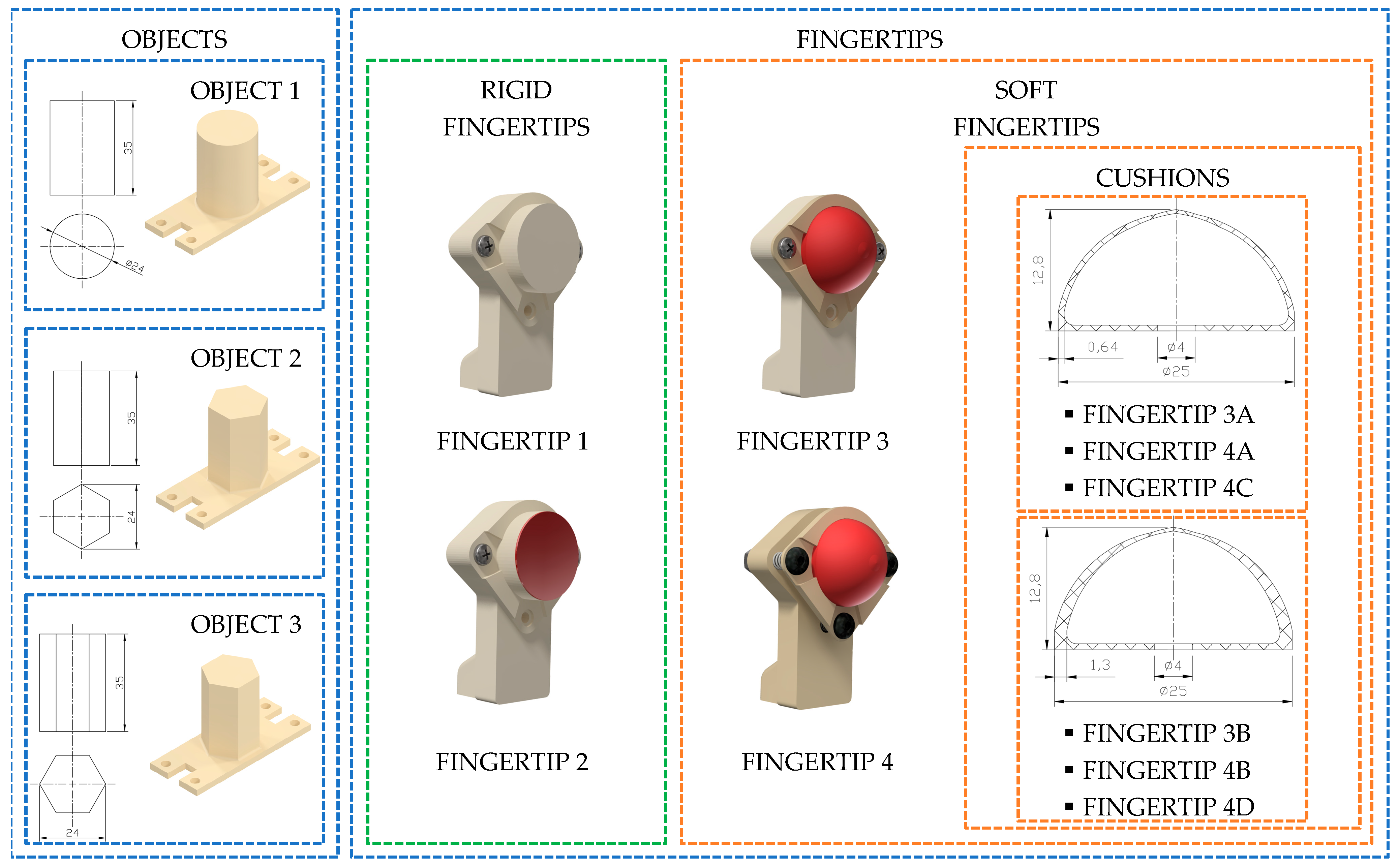
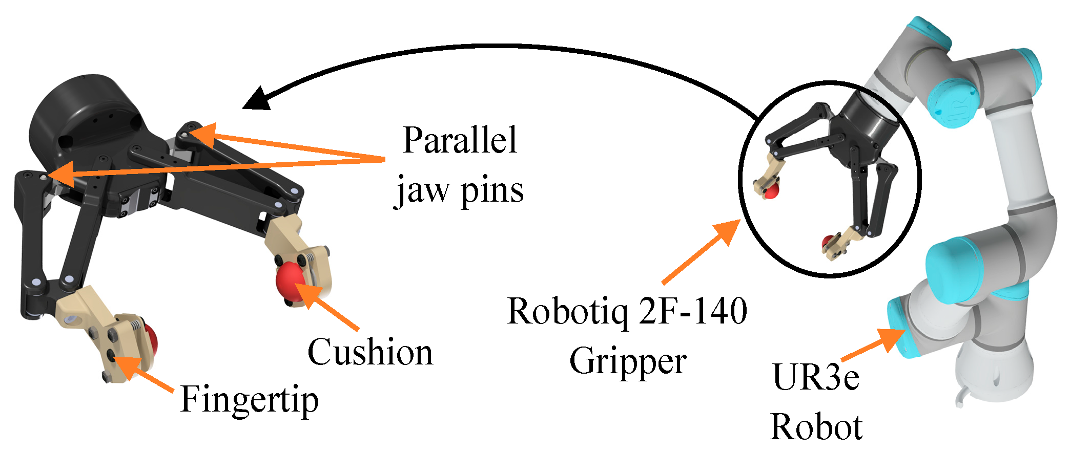
2.1. Manipulated Objects and Fingertips Characteristics
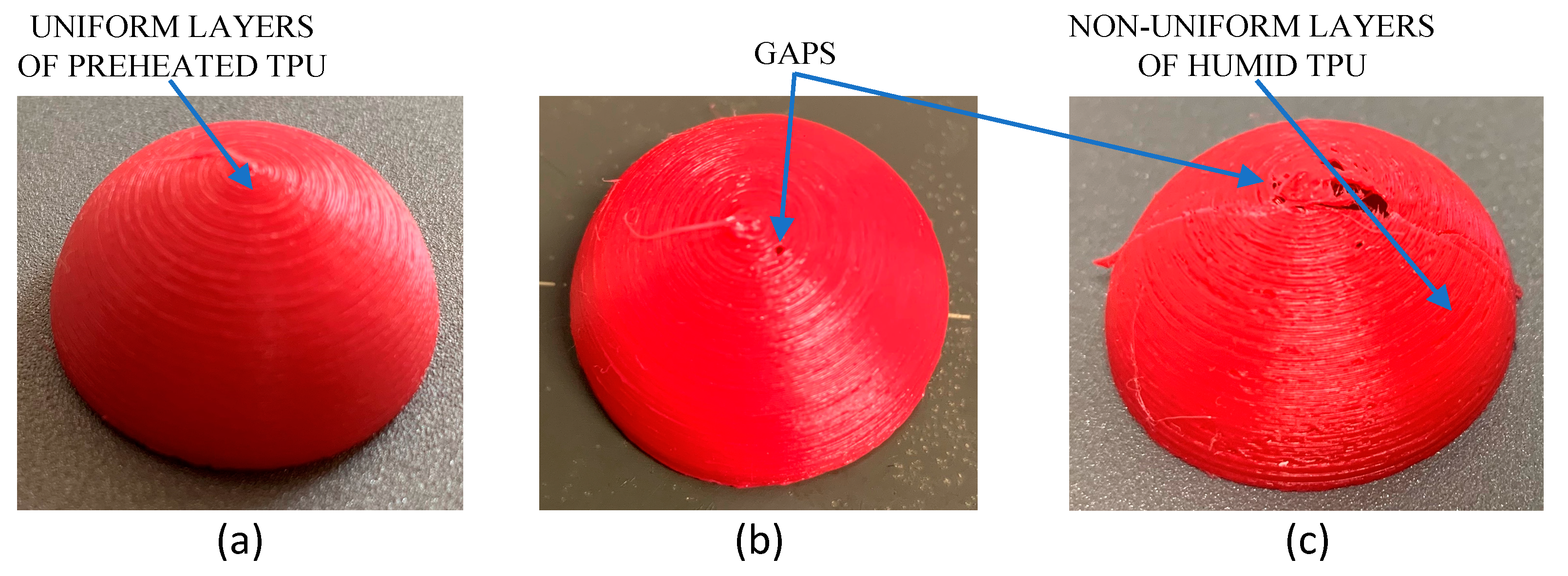
2.2. 3D printed Cushion
2.3. Cushion Prototypes
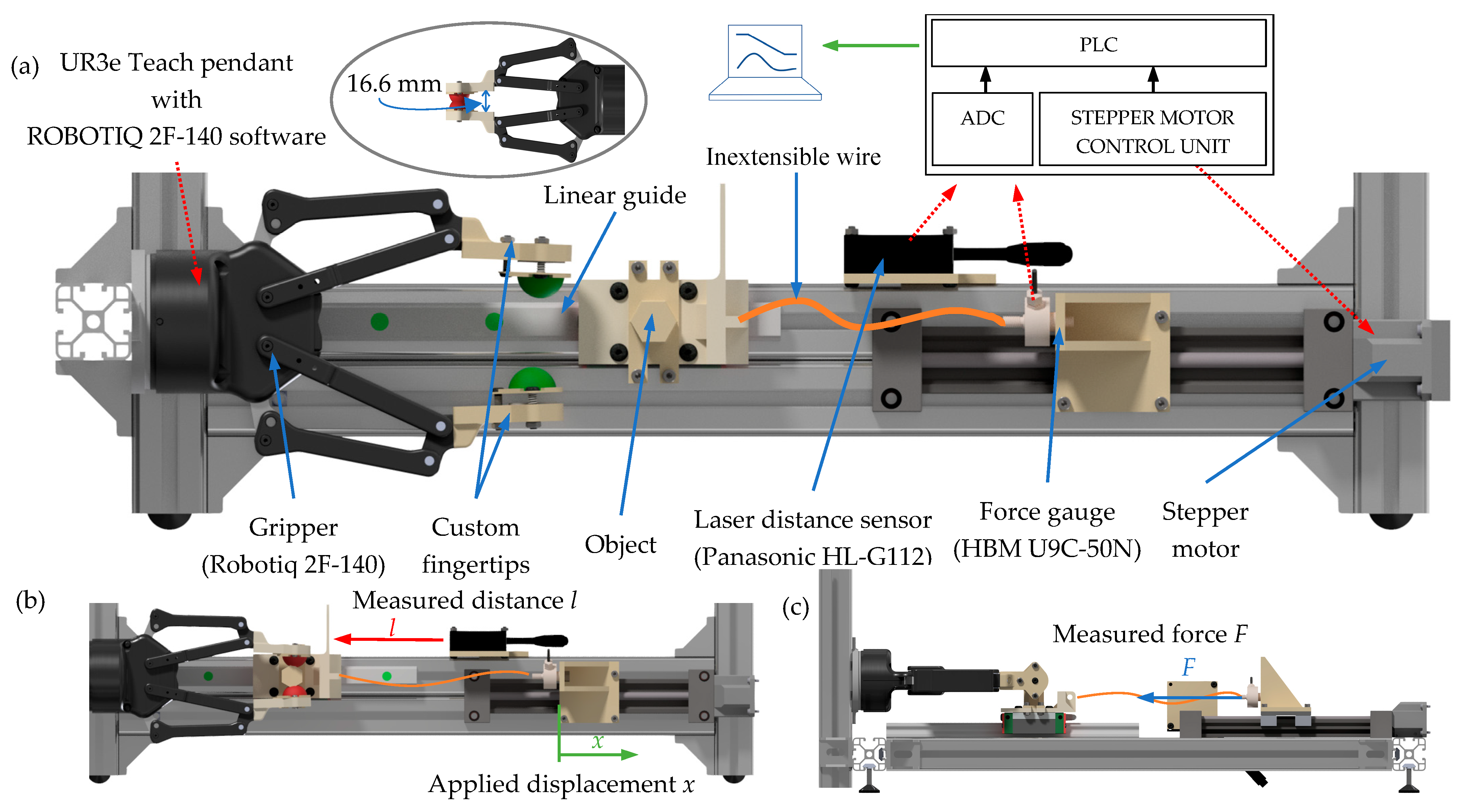
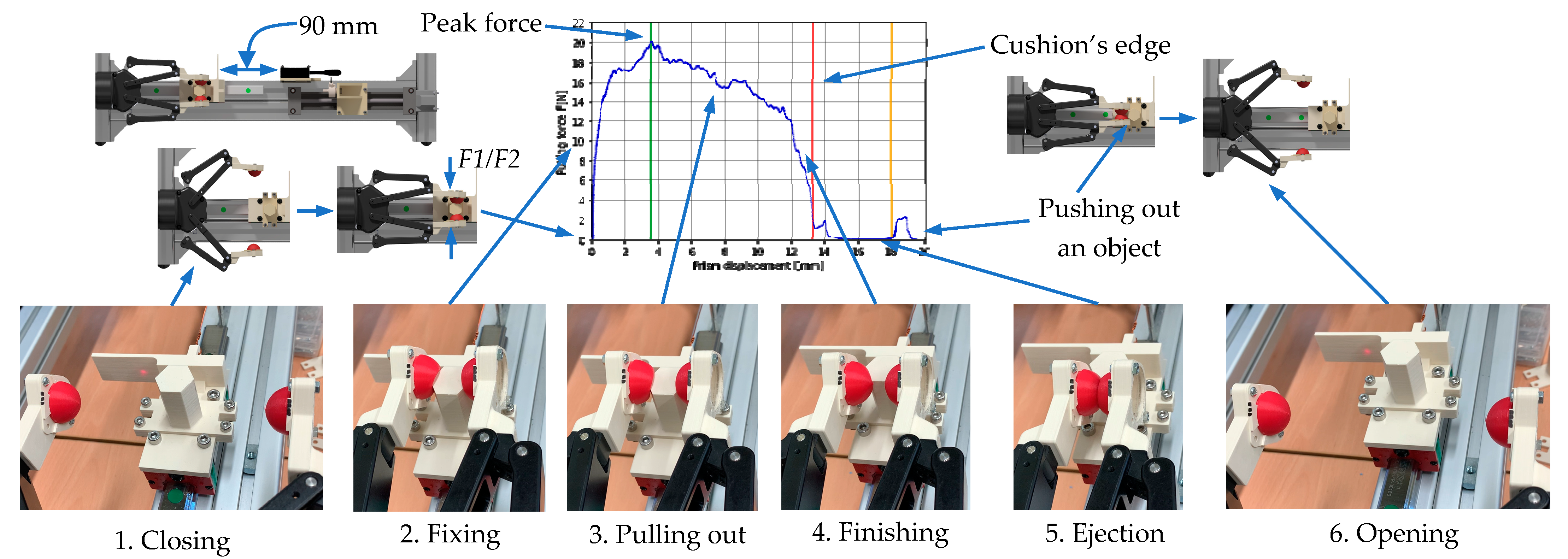
2.4. Test Stand
2.5. Methodology
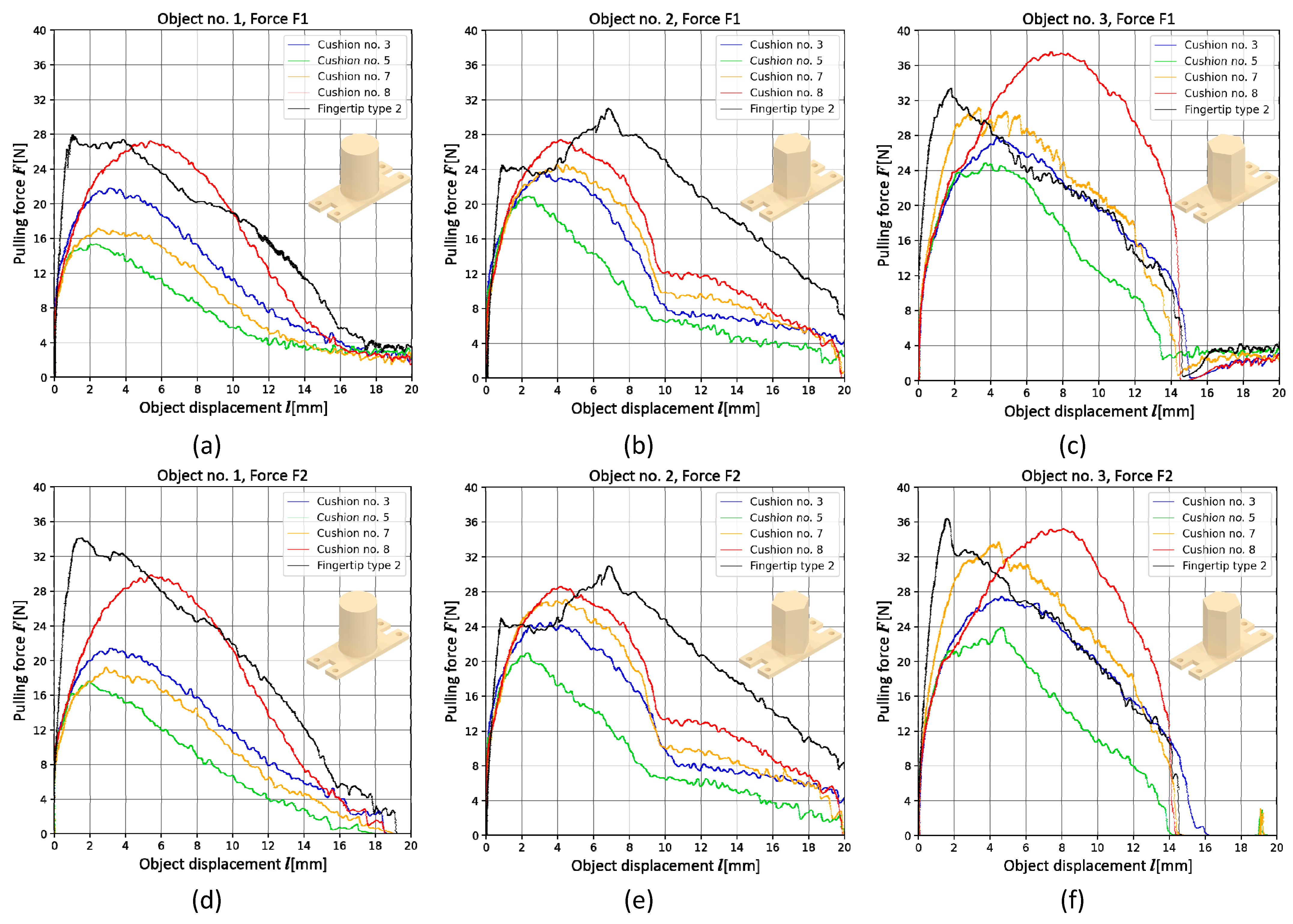
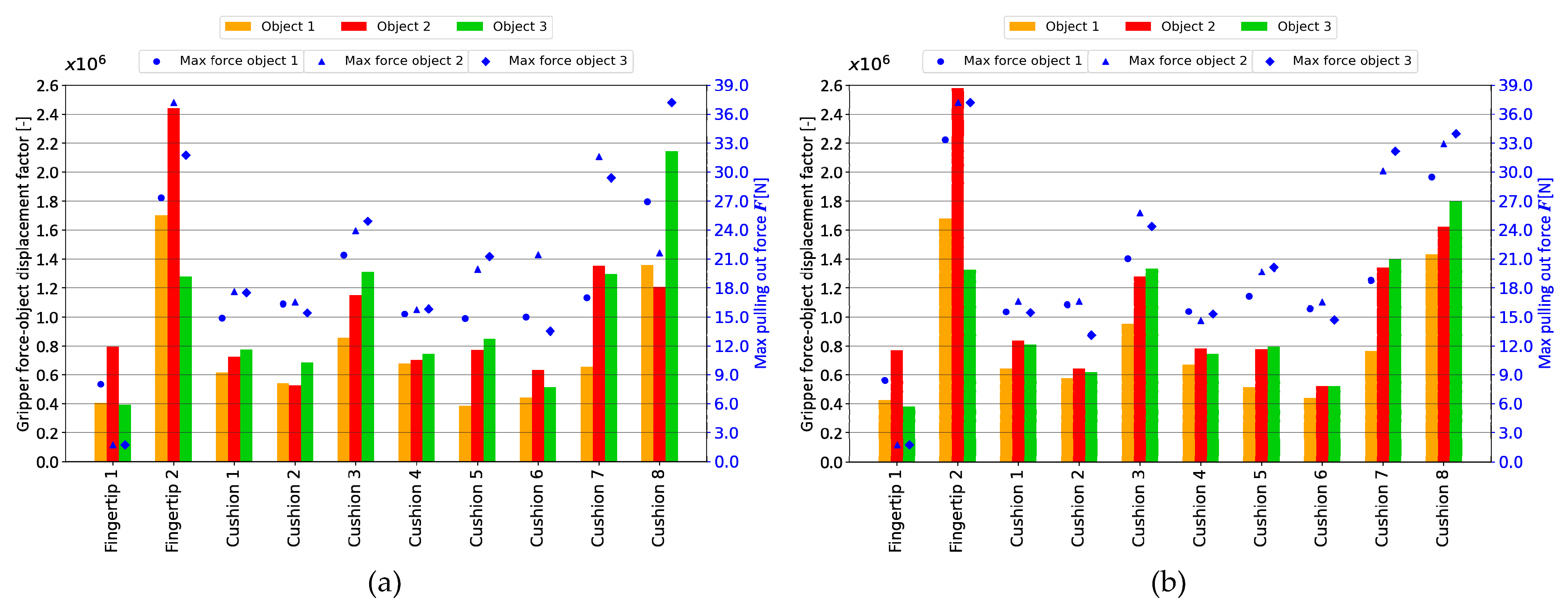
3. Results
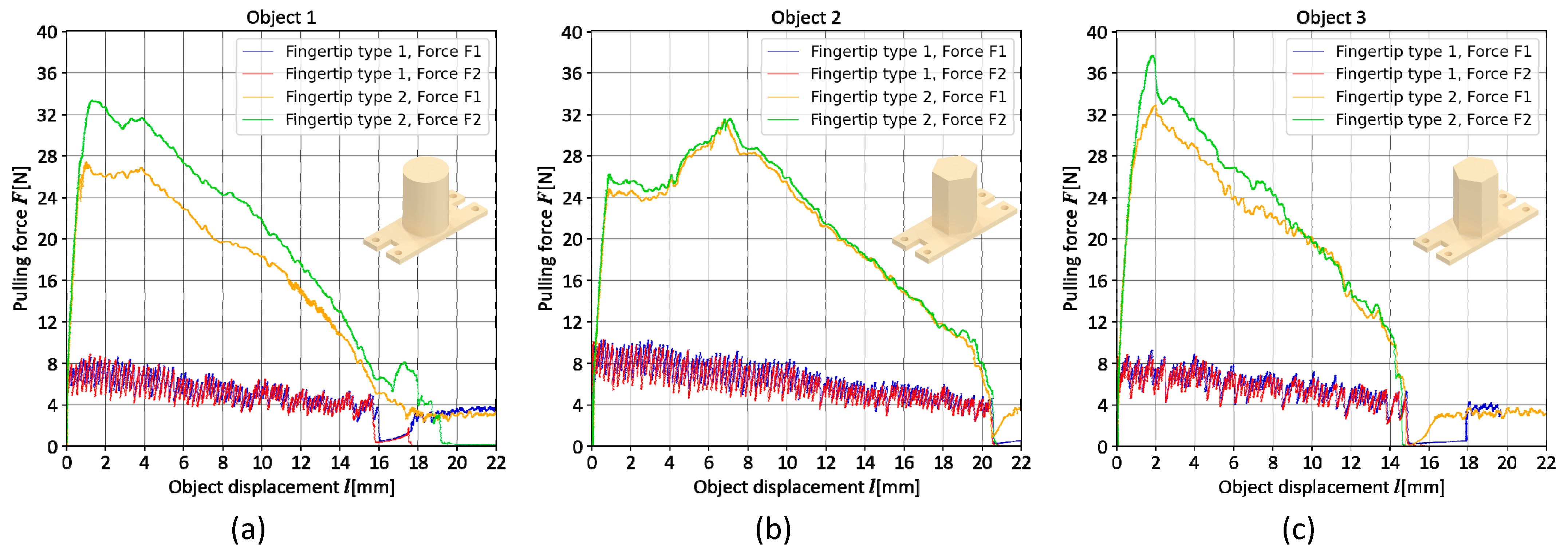
3.1. Fingertip Types 1 and 2
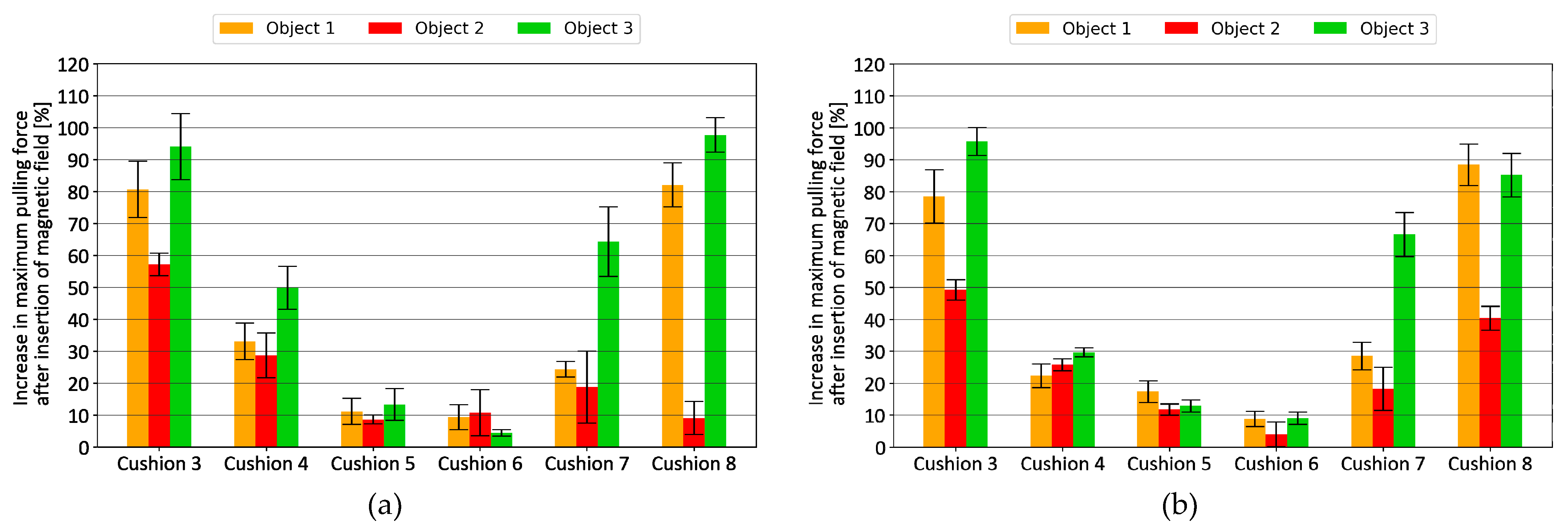
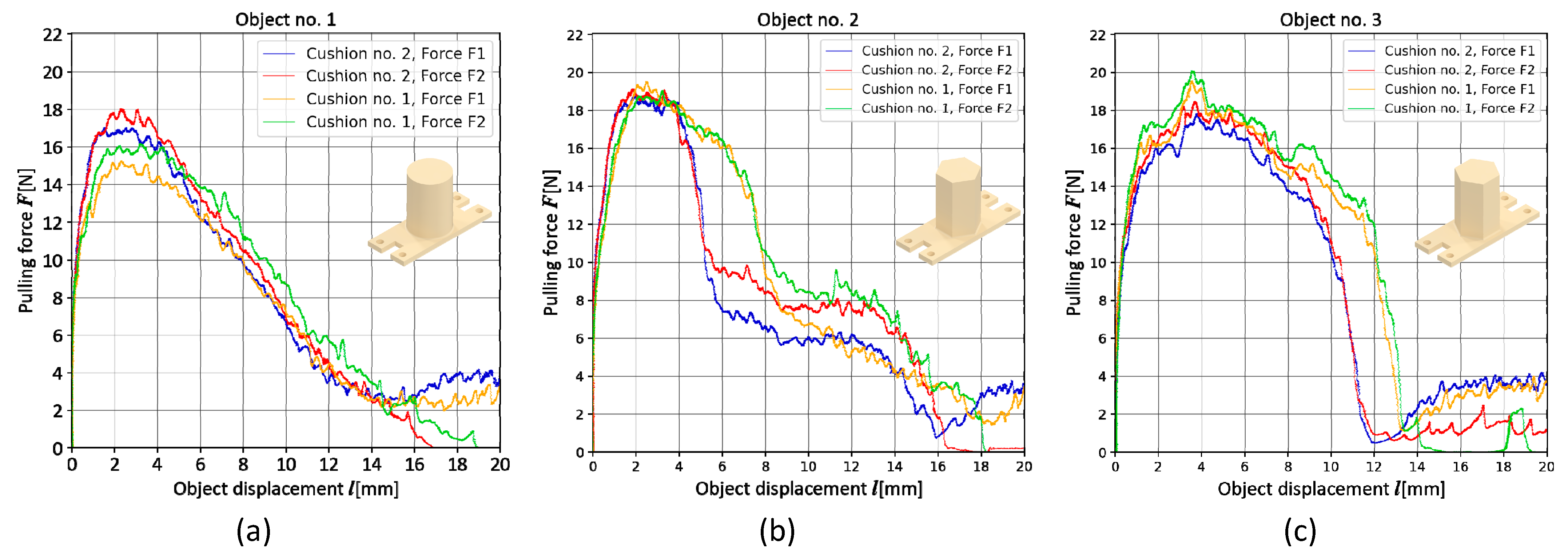
3.2. Fingertip Type 3
3.3. Fingertip Type 4
4. Discussion
5. Conclusions
Author Contributions
Funding
Institutional Review Board Statement
Informed Consent Statement
Data Availability Statement
Conflicts of Interest
References
- Terrile, S.; Argüelles, M.; Barrientos, A. Comparison of Different Technologies for Soft Robotics Grippers. Sensors 2021, 21, 3253. [Google Scholar] [CrossRef] [PubMed]
- Hughes, J.; Culha, U.; Giardina, F.; Guenther, F.; Rosendo, A.; Iida, F. Soft Manipulators and Grippers: A Review. Front. Robot. AI 2016, 3, 69. [Google Scholar] [CrossRef] [Green Version]
- Manti, M.; Hassan, T.; Passetti, G.; d’Elia, N.; Cianchetti, M.; Laschi, C. An Under-Actuated and Adaptable Soft Robotic Gripper. In Biomimetic and Biohybrid Systems; Wilson, S.P., Verschure, P.F.M.J., Mura, A., Prescott, T.J., Eds.; Lecture Notes in Computer Science; Springer International Publishing: Cham, Switzerland, 2015; Volume 9222, pp. 64–74. ISBN 978-3-319-22978-2. [Google Scholar]
- Yan, J.; Xu, Z.; Shi, P.; Zhao, J. A Human-Inspired Soft Finger with Dual-Mode Morphing Enabled by Variable Stiffness Mechanism. Soft Robot. 2022, 9, 399–411. [Google Scholar] [CrossRef] [PubMed]
- Liu, C.-H.; Chen, L.-J.; Chi, J.-C.; Wu, J.-Y. Topology Optimization Design and Experiment of a Soft Pneumatic Bending Actuator for Grasping Applications. IEEE Robot. Autom. Lett. 2022, 7, 2086–2093. [Google Scholar] [CrossRef]
- Xiao, W.; Liu, C.; Hu, D.; Yang, G.; Han, X. Soft Robotic Surface Enhances the Grasping Adaptability and Reliability of Pneumatic Grippers. Int. J. Mech. Sci. 2022, 219, 107094. [Google Scholar] [CrossRef]
- Yang, L.; Han, X.; Guo, W.; Wan, F.; Pan, J.; Song, C. Learning-Based Optoelectronically Innervated Tactile Finger for Rigid-Soft Interactive Grasping. IEEE Robot. Autom. Lett. 2021, 6, 3817–3824. [Google Scholar] [CrossRef]
- Cai, L.; Dong, S.; Huang, X.; Fang, H.; She, J. Mechanical Performance Analysis and Experimental Study of Soft-Bodied Bird-Billed Pneumatic Gripper. Ind. Robot. 2022, 49, 924–933. [Google Scholar] [CrossRef]
- Hughes, J.; Li, S.; Rus, D. Sensorization of a Continuum Body Gripper for High Force and Delicate Object Grasping. In Proceedings of the 2020 IEEE International Conference on Robotics and Automation (ICRA), Paris, France, 31 May–31 August 2020; pp. 6913–6919. [Google Scholar]
- Zhang, P.; Chen, W.; Tang, B. Design and Feasibility Tests of a Lightweight Soft Gripper for Compliant and Flexible Envelope Grasping. Soft Robot. 2022, 9, 376–385. [Google Scholar] [CrossRef]
- Mathew, B.P.; Devasia, F.; Asok, A.; Jayadevu, P.R.; Baby, R. Implementation of an Origami Inspired Gripper Robot for Picking Objects of Variable Geometry. Mater. Today Proc. 2022, 58, 176–183. [Google Scholar] [CrossRef]
- Li, S.; Lin, J.; Kang, H.; Cheng, Y.; Chen, Y. Bio-Inspired Origamic Pouch Motors with a High Contraction Ratio and Enhanced Force Output. Robot. Auton. Syst. 2022, 149, 103983. [Google Scholar] [CrossRef]
- Białek, M.; Jędryczka, C.; Milecki, A. Investigation of Thermoplastic Polyurethane Finger Cushion with Magnetorheological Fluid for Soft-Rigid Gripper. Energies 2021, 14, 6541. [Google Scholar] [CrossRef]
- Hong, S.-W.; Yoon, J.-Y.; Kim, S.-H.; Lee, S.-K.; Kim, Y.-R.; Park, Y.-J.; Kim, G.-W.; Choi, S.-B. 3D-Printed Soft Structure of Polyurethane and Magnetorheological Fluid: A Proof-of-Concept Investigation of Its Stiffness Tunability. Micromachines 2019, 10, 655. [Google Scholar] [CrossRef] [PubMed] [Green Version]
- Korger, M.; Glogowsky, A.; Sanduloff, S.; Steinem, C.; Huysman, S.; Horn, B.; Ernst, M.; Rabe, M. Testing Thermoplastic Elastomers Selected as Flexible Three-Dimensional Printing Materials for Functional Garment and Technical Textile Applications. J. Eng. Fibers Fabr. 2020, 15, 1558925020924599. [Google Scholar] [CrossRef]
- Nihal, R.A.; Broti, N.M.; Deowan, S.A.; Rahman, S. Design and Development of an Anthropomorphic Robotic Hand Using TPU Material. In Proceedings of the 2019 2nd International Conference on Innovation in Engineering and Technology (ICIET), Dhaka, Bangladesh, 23–24 December 2019; pp. 1–6. [Google Scholar]
- Balak, R.; Mazumdar, Y.C. Bistable Valves for MR Fluid-Based Soft Robotic Actuation Systems. IEEE Robot. Autom. Lett. 2021, 6, 8285–8292. [Google Scholar] [CrossRef]
- Somlor, S.; Aguirre Dominguez, G.; Schmitz, A.; Kamezaki, M.; Sugano, S. A Haptic Interface with Adjustable Stiffness Using MR Fluid. In Proceedings of the 2015 IEEE International Conference on Advanced Intelligent Mechatronics (AIM), Busan, Korea, 7–11 July 2015; pp. 1132–1137. [Google Scholar]
- Nishida, T.; Okatani, Y.; Tadakuma, K. Development of Universal Robot Gripper Using MRα Fluid. Int. J. Human. Robot. 2016, 13, 1650017. [Google Scholar] [CrossRef]
- Tsugami, Y.; Barbie, T.; Tadakuma, K.; Nishida, T. Development of Universal Parallel Gripper Using Reformed Magnetorheological Fluid. In Proceedings of the 2017 11th Asian Control Conference (ASCC), Gold Coast, QLD, Australia, 17–20 December 2017; pp. 778–783. [Google Scholar]
- Cramer, J.; Cramer, M.; Demeester, E.; Kellens, K. Exploring the Potential of Magnetorheology in Robotic Grippers. Procedia CIRP 2018, 76, 127–132. [Google Scholar] [CrossRef]
- Pettersson, A.; Davis, S.; Gray, J.O.; Dodd, T.J.; Ohlsson, T. Design of a Magnetorheological Robot Gripper for Handling of Delicate Food Products with Varying Shapes. J. Food Eng. 2010, 98, 332–338. [Google Scholar] [CrossRef]
- Hartzell, C.M.; Choi, Y.T.; Wereley, N.M.; Leps, T.J.G. Performance of a Magnetorheological Fluid-Based Robotic End Effector. Smart Mater. Struct. 2019, 28, 035030. [Google Scholar] [CrossRef]
- Naimzad, A.; Ghodsi, M.; Hojjat, Y.; Maddah, A. MREs Development and Its Application on Miniature Gripper. Proc. Int. Conf. Adv. Mater. Eng. 2011, 15, 75–80. [Google Scholar]
- Skfivan, V.; Sodomka, O.; Mach, F. Magnetically Guided Soft Robotic Grippers. In Proceedings of the 2019 2nd IEEE International Conference on Soft Robotics (RoboSoft), Seoul, Republic of Korea, 14–18 April 2019; pp. 126–130. [Google Scholar]
- Choi, Y.T.; Hartzell, C.M.; Leps, T.; Wereley, N.M. Gripping Characteristics of an Electromagnetically Activated Magnetorheological Fluid-Based Gripper. AIP Adv. 2018, 8, 056701. [Google Scholar] [CrossRef] [Green Version]
- Liu, Q.; Jing, T.; Mo, A.; Xu, X.; Zhang, W. A Novel Robot Hand with the Magneto-Rheological Fluid Solidification. In Proceedings of the 2015 IEEE International Conference on Robotics and Biomimetics (ROBIO), Zhuhai, China, 6–9 December 2015; pp. 2495–2500. [Google Scholar]
- Wang, Y.; Yang, Z.; Zhou, H.; Zhao, C.; Barimah, B.; Li, B.; Xiang, C.; Li, L.; Gou, X.; Luo, M. Inflatable Particle-Jammed Robotic Gripper Based on Integration of Positive Pressure and Partial Filling. Soft Robot. 2022, 9, 309–323. [Google Scholar] [CrossRef] [PubMed]
- LORD MRF-140CG Documentation Site. Available online: https://lordfulfillment.com/pdf/44/DS7012_MRF-140CGMRFluid.pdf (accessed on 20 December 2022).
- Arus MR Tech RHEOTEC+ Documentation Site. Available online: https://arusmrtech.com/wp-content/uploads/2021/11/RHEOTEC.pdf (accessed on 20 December 2022).
- PrusaSlicer Site. Available online: https://www.prusa3d.com/page/prusaslicer_424/ (accessed on 20 December 2022).
- Turekova, I.; Szabova, Z.; Chrebet, T.; Harangozo, J. The Effect of External Conditions on Ignition Temperature of Thermoplastic Polyurethane Elastomers. Adv. Mater. Res. 2013, 838–841, 14–17. [Google Scholar] [CrossRef]
- B&R Site. Available online: https://www.br-automation.com/ (accessed on 20 December 2022).


| MR FLUID | LORD MRF-140CG | ARUS MR TECH RHEOTEC+ |
|---|---|---|
| Viscosity, [Pa-s] (at 40 °C) | 0.280 ± 0.070 | 0.240 ± 0.027 |
| Density [g/cm3] | 3.54–3.74 | 3.1–3.3 |
| Solids Content by Weight [%] | 85.44 | 84 |
| Maximum Yield Stress [kPa] at 180 kA/m | 69 ± 5 | ~57 |
| Age | ~10 years | Factory new |
| Visible remarks | Dense, low oil content due to sedimentation | Liquid-like |
| Printer | Model | Prusa i3 MK3S+ |
| Nozzle | 0.4 mm | |
| Slicer | PrusaSlicer | |
| Print Settings | Layer height | 0.1 mm |
| Layers speed | 20 mm/s | |
| Flowrate | 130% | |
| Support material | No | |
| Fan | Always on | |
| Seam position | Random | |
| Filament | manufacturer | print-me.pl |
| Product name | PrintMe Flex | |
| Shore hardness | 20D | |
| Density | 1.15 g/cm3 | |
| Time of printing | Time of printing | 1 h 22 m |
| Cushion Model | Fingertip Model | Infill | Infill Volume | Visible Remarks |
|---|---|---|---|---|
| Cushion 1 | Fingertip 3A | AIR | - | hemisphere |
| Cushion 2 | Fingertip 3B | AIR | - | hemisphere |
| Cushion 3 | Fingertip 4A | MRF-140 CG | MRF: 2.6 mL | concave hemisphere |
| Cushion 4 | Fingertip 4B | MRF-140 CG | MRF: 2.6 mL | concave hemisphere |
| Cushion 5 | Fingertip 4C | RHEOTEC+ | MRF: 2.6 mL | concave hemisphere |
| Cushion 6 | Fingertip 4D | RHEOTEC+ | MRF: 2.6 mL | concave hemisphere |
| Cushion 7 | Fingertip 4C | RHEOTEC+ & microbeads | MRF: 1.6 mL Beads: 1 mL (1.6 g) | concave hemisphere |
| Cushion 8 | Fingertip 4A | MRF-140 CG & microbeads | MRF: 1.6 mL Beads: 1 mL (1.6 g) | concave hemisphere |
| Force Description | UR3e Teach Pendant Designation | Actuation Force Value | Remarks |
|---|---|---|---|
| Force F1 | 0% | ~15 N | Regrasp off: When an object is pulled out, the jaws remain in their position |
| Force F2 | 10% | ~15 N | Regrasp on: When an object is pulled out, the jaws close |
Disclaimer/Publisher’s Note: The statements, opinions and data contained in all publications are solely those of the individual author(s) and contributor(s) and not of MDPI and/or the editor(s). MDPI and/or the editor(s) disclaim responsibility for any injury to people or property resulting from any ideas, methods, instructions or products referred to in the content. |
© 2023 by the authors. Licensee MDPI, Basel, Switzerland. This article is an open access article distributed under the terms and conditions of the Creative Commons Attribution (CC BY) license (https://creativecommons.org/licenses/by/4.0/).
Share and Cite
Białek, M.; Rybarczyk, D. A Comparative Study of Different Fingertips on the Object Pulling Forces in Robotic Gripper Jaws. Appl. Sci. 2023, 13, 1247. https://doi.org/10.3390/app13031247
Białek M, Rybarczyk D. A Comparative Study of Different Fingertips on the Object Pulling Forces in Robotic Gripper Jaws. Applied Sciences. 2023; 13(3):1247. https://doi.org/10.3390/app13031247
Chicago/Turabian StyleBiałek, Marcin, and Dominik Rybarczyk. 2023. "A Comparative Study of Different Fingertips on the Object Pulling Forces in Robotic Gripper Jaws" Applied Sciences 13, no. 3: 1247. https://doi.org/10.3390/app13031247
APA StyleBiałek, M., & Rybarczyk, D. (2023). A Comparative Study of Different Fingertips on the Object Pulling Forces in Robotic Gripper Jaws. Applied Sciences, 13(3), 1247. https://doi.org/10.3390/app13031247