Article

Field Inspection of High-Density Polyethylene (HDPE) Storage Tanks Using Infrared Thermography and Ultrasonic Methods

1
Virginia Transportation Research Council, 530 Edgemont Rd, Charlottesville, VA 22903, USA
2
Charles E. Via, Jr. Department of Civil and Environmental Engineering, Virginia Polytechnic Institute and State University, Blacksburg, VA 24061, USA
3
Department of Materials Science and Engineering, Virginia Polytechnic Institute and State University, Blacksburg, VA 24061, USA
*
Authors to whom correspondence should be addressed.
Appl. Sci. 2023, 13(3), 1396; https://doi.org/10.3390/app13031396
Submission received: 4 January 2023 / Revised: 17 January 2023 / Accepted: 18 January 2023 / Published: 20 January 2023
(This article belongs to the Special Issue Advances in Nondestructive Testing and Evaluation)

Abstract

:
High-density polyethylene (HDPE) is widely used for above-ground storage tanks (ASTs). However, there are currently no guidelines for the non-destructive testing (NDT) and evaluation (NDE) of HDPE ASTs. Moreover, the feasibility, limitations, and challenges of using NDT techniques for the field inspection of HDPE ASTs have not been well established. This study used both infrared thermography (IRT) and ultrasonic testing (UT) for the field inspection of HDPE ASTs. Highlighting the implementation challenges in the field, this study determined that: (1) ambient environmental parameters can affect IRT accuracy; (2) there is an ideal time during the day to perform IRT; (3) the heating source and infrared camera orientation can affect IRT accuracy; and (4) with proper measures taken, IRT is a promising method for flaw detection in HDPE ASTs. Additionally, UT can be used following IRT for detailed investigation to quantify the size and depth of defects. The manuscript concludes with a discussion of the limitations and best practices for the implementing of IRT and UT for HDPE AST inspections in the field.

1. Introduction

State departments of transportation (DOTs) in the United States use high-density polyethylene (HDPE) above-ground storage tanks (ASTs) to store deicing solutions for use in roadway maintenance in winter. HDPE ASTs can also be used to store sodium hypochlorite, sulfuric acid, ferric chloride, ferric sulfate, alums, polymers, biodiesel, fertilizers, phosphoric acid, sodium hypochlorite, sulfuric acid, urea, brine, agricultural chemicals, industrial chemicals, and many other chemicals used in wastewater treatment and industrial processes. HDPE ASTs are typically designed to contain from 7600 L to 56,800 L (2000 gallons to 15,000 gallons) of liquid, and the tanks are either single- or double-walled.
Although HDPE has unique properties and advantages compared to other materials, such as cost efficiency, corrosion resistance, a resistance to leaching, outstanding tensile strength, a large strength-to-density ratio, high-impact resistance, a high melting point, low maintenance requirements, and the ability to last in different types of environments, HDPE does have a relatively poor weathering resistance (e.g., poor resistance to ultraviolet radiation) and is susceptible to stress cracking [1,2]. When HDPE is utilized in high-capacity ASTs, the disadvantages of the material become crucial. Sudden, catastrophic AST failures endanger people and property and cause environmental, ecological, and economic losses [2,3,4,5,6]. To ensure functionality and integrity, these ASTs are routinely inspected to identify signs of aging and damage in an effort to prevent catastrophic failures. Relatively few studies have been performed on non-destructive testing (NDT) for the inspection of HDPE ASTs (e.g., [7,8,9]). Previous laboratory-based NDT studies by the authors showed that infrared thermography (IRT) and ultrasonic testing (UT) techniques were helpful in detecting and measuring the defects located in a simulated HDPE tank wall [8,9]. These studies also showed that the HDPE sample size and thickness, exterior tank surface temperature, interior liquid temperature, ambient temperature, and relative humidity all affect defect detection and the threshold of the defect size that can be detected.
However, one limitation is the lack of guidelines for NDT inspections of HDPE ASTs, despite guidelines existing for steel tanks (e.g., Steel Tank Institute’s STI SP00l, American Petroleum Institute’s API Standard 653). Therefore, one goal of this study is to investigate the efficiency of using IRT and UT during field inspections of HDPE ASTs in order to transfer the data from previous laboratory studies into practice and, if needed, apply some changes and/or corrections for a more accurate inspection. The other goal of this study is to provide a set of guidelines for state DOTs, manufacturers, and other commercial agencies or industries to follow and complete a more systematic and efficient tank integrity inspection.

2. Experiment Methodology

This study was completed by performing IRT and UT tests on a single-walled HDPE tank with a capacity of 6000 gallons (22,700 L). The tank had been decommissioned from use after 15 years of service storing brine solutions for winter maintenance. The bottom 1.25 m (4.1 ft) of the tank had a thickness of 19.1 mm (0.75 in) and the remaining height of the tank had a thickness of 12.7 mm (0.5 in). Defects of known size and location were created, as discussed in Section 2.4, to simulate subsurface anomalies. These defects were used to establish the effectiveness of the NDT methods. The defects were created on both the east and west sides of the tank in order to study the best time frame for evaluation, with regard to a specific side of the tank being in the sun or the shade. After the defects were created inside the tank, the tank was filled with 5000 gallons (18,900 L) of water.

2.1. Temperature Collection

The authors’ previous laboratory studies showed that the temperature difference between the tank wall and the liquid inside the tank affects the size limit of the defect detection [8,9]. Thermocouples, connected to a data logger, were used to monitor the time-dependent temperatures of the tank surface and the liquid inside the tank. The thermocouples were installed at the top, middle, and bottom of the tank wall exterior on both the east and west sides close to where the defects exist. The thermocouples were installed on the tank wall by sandwiching them between the tank and a piece of HDPE (Figure 1), and the gaps between the tank wall and the small pieces of HDPE were sealed with hot glue to ensure that only the temperature of the HDPE is collected. One thermocouple was submerged in the water inside the tank, and one thermocouple was stored next to the tank in the shade to collect the ambient temperature. The data logger collected temperatures every minute and recorded the average of the collected temperatures every 30 min. The temperature data were collected over 230 days during testing.

2.2. Infrared Thermography (IRT)

Every material emits infrared (IR) radiation at a specific wavelength that is dependent upon its thermal properties (i.e., thermal conductivity and thermal capacity). IRT employs a thermal imager to capture the infrared radiation from a given surface, transforming it into electrical signals equivalent to the surface temperature profile. These signals are displayed in the form of colorful thermal images known as thermograms, in which each color corresponds to a temperature on the object’s surface [8,10,11]. Usually, defects have different thermal properties compared to the intact original homogeneous solid [12], since the defects are often filled with air or a liquid. The difference in the thermophysical parameters between the original material and the defects allows for the effective application of IRT to detect subsurface defects [12]. In order to detect any defects or flaws, a thermal gradient must exist through the depth of the element, which can be generated through either passive or active methods. Deposited heat on the sample surface diffuses toward the interior side of the object and the presence of a subsurface flaw blocks the heat flow, resulting in defect detection in the thermograms. The crucial difference between the passive and active methods is that, in passive IRT, the ambient environment and sunlight are used to generate the thermal gradient on the component depth, but, in active IRT, the component is artificially thermally excited (e.g., using light, hot or cold air, direct contact) and observed with an IR camera as it responds to the thermal stimulus [12,13].
According to the method and duration of the heating and thermographic data analysis procedures, the active thermography techniques fall into the following subcategories: pulsed thermography, step-heating thermography, modulated lock-in thermography, vibrothermography, pulse-compression thermography, and thermal wave imaging [12,14,15,16,17]. Moreover, active thermography can be classified into reflection and transmission methods, depending on the heating and measurement setups. If the imposed thermal gradient is generated from the same side of the object as the IR camera, then the technique is known as the reflection method and is used to locate superficial anomalies. If the heating is applied on the opposite side of the object from the IR camera, then the technique is known as the transmission method, which is used to identify deep anomalies. Since the goal of this study is to implement IRT in the field for the integrity evaluation of HDPE ASTs, and since only the outside of the AST is accessible when it is filled with brine solution, the reflection method is the primary focus of this research, as has been established in previous studies [8,9].
In active IRT schemes, different external excitation sources can be used, such as optical lamps [18], microwaves [19], ultrasonic pulses [20], hot and cold air [21,22], eddy currents [23], etc. First, during the preliminary investigations, this study tried to use the same experiment setup established in previous research [8], which utilized six 500 W halogen lamps with a total power of 3000 W at a distance of 0.4 m (15.75 in) to induce a thermal gradient on the object surface. The heating power used in the previous laboratory experiment was not sufficient to induce an adequate thermal gradient on the HDPE AST wall in the field. Therefore, the first correction for transferring the IRT from the laboratory to the field was changing the heating source. The preliminary investigations showed that utilizing two stacked 1500 W infrared heaters with a total power of 3000 W at a distance of 0.4 m (15.75 in) was effective for defect detection in the field for this study.
Step heating involves heating the tank for a predetermined amount of time, and then letting the tank cool naturally for a predetermined amount of time. Previous studies utilized the step heating method with three minutes of continuous heating [8,9]. Due to the semi-infinite size of the HDPE AST, compared to the laboratory-scale water tank used in previous studies, the IRT technique, with step heating—even with 10 min of continuous heating—was not efficient for the field investigation in this study. Short-step heating was not enough to induce an adequate thermal gradient and to therefore obtain an observable contrast between the defects and the intact areas; on the other hand, long-step heating reduced the contrast between the defect edge and the original solid area. Therefore, according to the preliminary investigations, step-heating and thermal wave imaging were combined for this study. To induce waveform heat, the heat was deposited on the surface by following alternative heating and cooling cycles. For this study, the grouping of one heating phase and one cooling phase is termed one cycle. Different heating and cooling duration combinations were considered for this study (Table 1) to investigate the optimum heating–cooling cycles. For each combination of heating–cooling durations (e.g., 20 s heating with 60 s cooling), six cycles were completed and the IRT was conducted during each cooling phase. The first two cooling phase durations per heating time group were kept constant (e.g., 10 s and 20 s), and the subsequent four cooling phase durations were changed as a function of the heating time duration. This arrangement in selecting the cooling phase duration was chosen for the sake of the practical implementation and a faster field investigation. The length of the heating phase is only a fraction of the cooling phase, enabling an inspector to perform multiple thermal cycles across the tank simultaneously. For instance, in the combination of 20 s heating and 140 s cooling, the inspector can heat seven areas (7 × 20 s = 140 s) and then return to the first spot to start the second cycle of IRT measurement. This heating–cooling cycle allows the heat to penetrate the sample in the form of waves without reducing the contrast between the defects and the sounding area. Therefore, the authors believe that applying a waveform heat distribution on the HDPE AST causes the heat to penetrate deeper, increasing the contrast between the defect edges, and consequently revealing more subsurface defects. For this reason, the optimum heating–cooling durations need more investigations relative to what was established by the authors in the previous two studies. The IRT evaluation and measurement for each heating–cooling combination were completed twice: one was performed in the morning and one was performed in the afternoon; this reasoning is explained in Section 3.1.
For this study, a Fluke TiX580 thermal imager (IR camera), with the features shown in Table 2, was used. The IR camera settings used in this study can be found in Table 3. The distance between the camera and the object varied from 0.8 m to 1.1 m (2.6 ft to 3.6 ft). Inspectors in the field are interested in evaluating as many tanks as possible in one day, without performing further analysis. Therefore, in order to expedite the field investigation, the temperature span on the camera was set to automatic. In the previous studies performed by the authors, the camera was set manually which narrows down the temperature range for better defect detection, but is also more time consuming. No further image processing was performed and the smallest detected defect size was obtained directly from the raw images; this was performed to facilitate the evaluation process and speed it up for the sake of field implementation.

2.3. Ultrasonic Testing (UT)

While the IRT reflection technique can help to identify the existence of superficial subsurface defects, IRT is not able to quantify the defect depth, defect size, or whether there are stacked defects. Therefore, UT, specifically phased array ultrasonic testing (PAUT), was used as a supplementary technique for defect quantification. PAUT probes are composed of multiple ultrasonic elements that act as a synthetic aperture to “sweep” its focus without moving the probe [24,25], thereby providing significantly more versatility and range than conventional pulse-echo methods. Since the probe’s focus is “swept,” even defects that are stacked can be detected, which would not be possible by conventional pulse-echo methods [26]. PAUT has shown great capabilities to detect embedded defects in HDPE pipes and joints [27,28,29,30,31,32,33].
By calibrating the measuring equipment to the P-wave velocity of the AST material with knowledge of the wall thickness and object temperature, PAUT can locate hidden abnormalities. One disadvantage of the application of UT to HDPE is the potential for significant acoustic attenuation and dispersion due to the viscoelasticity of HDPE, with energy losses reported from 7 dB/cm (18 dB/in) to as much as 15 dB/cm (38 dB/in) [26,27,34]. Therefore, based on the AST wall thickness and defect size, a range of ultrasonic frequencies needs to be considered; for instance, while higher frequencies will likely yield a better resolution, the signal will diminish due to increased scattering [35]. Another challenge with PAUT is that more peaks are generated in the response signals from deep defects as a result of waves propagating through the irregularly damaged area, intact area, and corner. The extra signals make it difficult to determine the defect tip and starting point, which are necessary for determining the geometry and location of the defect. This limitation in the technique is known as a corner trap.
In this research, a Proceq Flaw Detector 100 ultrasonic instrument was used in combination with a phased array water wedge probe from SensorScan with 2.25 MHz. Water wedges have been used in other UT studies of HDPE [8,30,31,32], primarily because the relatively slow acoustic velocity of HDPE would result in a negative refraction from other commonly-used PAUT wedge materials. A wave velocity calibration was performed with a pulse-echo probe before starting each measurement. The settings used for the calibration are summarized in Table 4.
A previous study showed that the thickness of the HDPE—at least the thickness of typical HDPE AST walls—does not impact the sound wave velocity measurement [8]. The HDPE temperature does affect velocity such that, as the temperature decreases, the sound wave velocity increases [8,36,37]. In addition, it has been shown that the outdoor weathering of HDPE ASTs does not appear to considerably affect the sound wave velocity [8]. Therefore, provided that the wave velocity is calibrated before measurement, PAUT is recommended as a supplementary technique to IRT.

2.4. Defects Created Inside the Tank

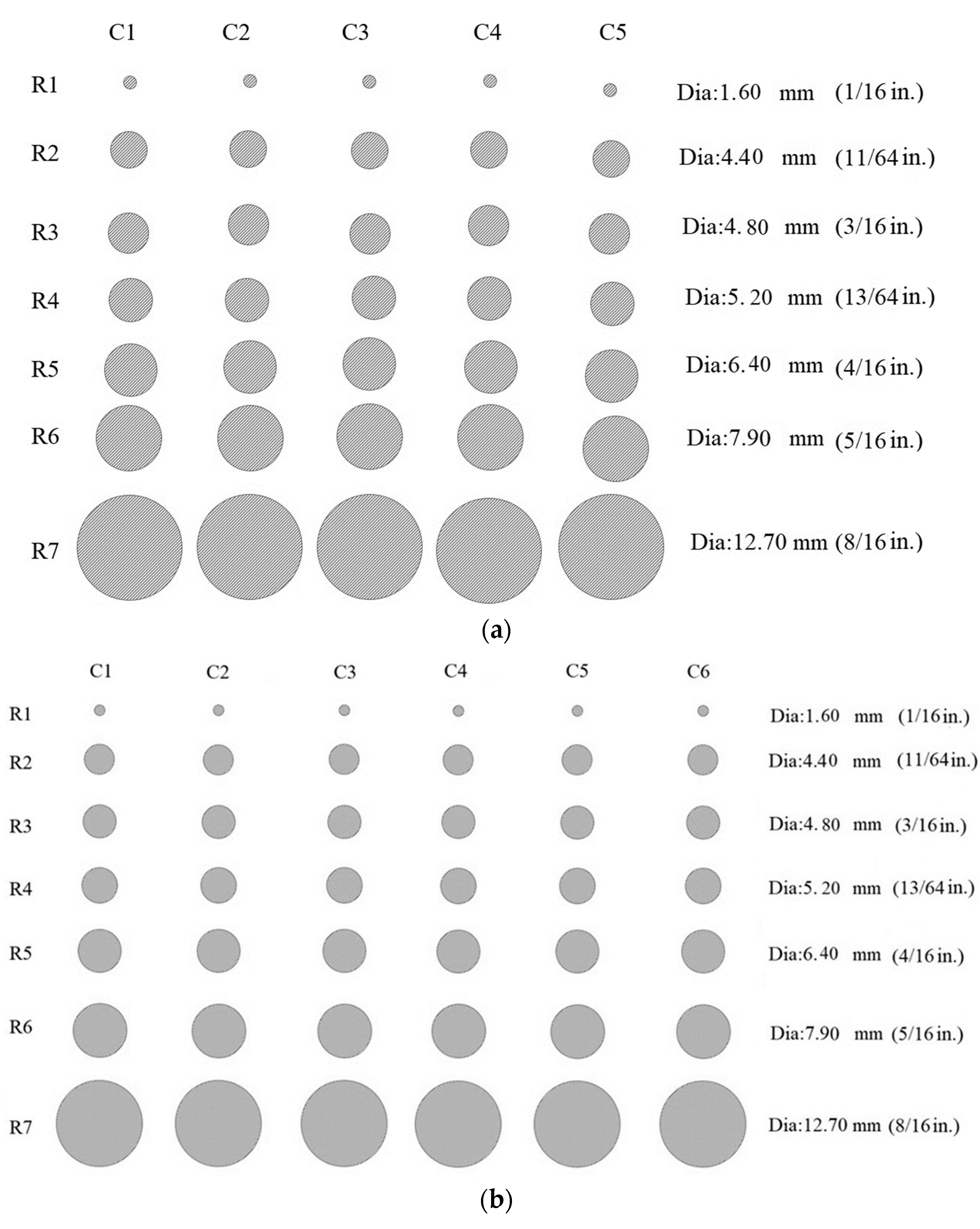
Two sets of defects with varying diameters and depths were created in the tank wall from the inside to simulate subsurface defects. One set of the defects was created on the east side and the thinner part of the tank, which had a thickness of 12.7 mm (0.5 in), and the other set of defects was created on the west side in the thicker part of the tank, which had a thickness of 19.1 mm (0.75 in). The configuration of both sets is shown in Figure 2. The characteristics of the defects are summarized in Table 5 and Table 6. The defects are labeled according to their relative location, where “R” refers to the row and “C” refers to the column of the defect set. For example, the R2C4 defect refers to the defect located in Row 2 and Column 4. In Table 5 and Table 6, the aspect ratio (AR) is equal to the ratio of the defect diameter (d) to the defect depth (D) (AR = d/D), and D/t is the ratio of the defect depth to the wall thickness (t). The defect depth is reported relative to the external surface.
Since the defects were created manually using a cordless drill and since the AST wall is curved, the depth of the defects could not be controlled with the same accuracy as the previous studies. Due to the size of the tank, the dangerous consequences of the tank failing during the study, and the concentration of the defects in a small area, it was risky to create four sets of defects on the tank to study the impact of both wall thickness and the location of the defects on the measurements. Therefore, one set of defects was made on the thin part and the other set was created on the thick part of the tank wall.

3. Results and Discussion

3.1. Temperature Collection

The initial temperature gradient in the tank wall (ΔT = Twall surface − Twater) impacts the measurement and defect detection threshold [8,9]. Therefore, it is necessary to study the best time frame for conducting the IRT evaluation on an HDPE AST in the field. During different times of the day, one half of the tank is sun-faced and the other half is shade-faced; therefore, the uneven heat received from the sun can induce a non-uniform temperature on the tank, as shown by IRT in Figure 3. The tank wall temperatures recorded over 230 days are shown in Figure 4. The east and west sides were selected for temperature monitoring because of how the tank was positioned: the east side is sun-faced in the morning while the west side is shade-faced and vice versa. Figure 4a shows the temperatures recorded at 10:30 a.m. when the sun is on the east side, and Figure 4b shows the temperature at 4:30 p.m. when the sun is on the west side of the tank. According to the weathering data, in the area where the study has been conducted, the sunrise time varied between 5:54 a.m. to 7:48 a.m. in different months and the sunset time varied from 4:54 p.m. to 8:43 p.m. Figure 4 shows that the temperature of the tank wall varies from east to west depending on the sun’s direction. In the morning, the east side of the tank has a higher temperature, and in the afternoon, the west and east sides of the tank have comparable temperatures. In the afternoon, the temperature of the tank wall on both sides increased from the heat accumulation that had started from sunrise. Figure 5 shows the temperatures on the tank wall on two random cloudy days; the temperatures of both the east and west sides are similar and fall between the water and ambient temperatures. In other words, on cloudy days, there is a negative initial thermal gradient (ΔT < 0) on the tank wall, which, according to the previous studies [8,9], is not suitable for completing IRT evaluation. This was verified for all of the data gathered, and the same pattern was seen on all cloudy days. Figure 6 shows examples of tank temperature changing behavior on sunny days during summer and winter. As seen, the peak temperature for the east and west sides shifted due to the sunlight direction changes in the morning and the evening. Moreover, in most cases, there was a positive initial thermal gradient (ΔT > 0) on the tank wall thickness between 9:00 a.m. to 6:00 p.m., which is suitable for performing IRT. Therefore, this implies that the best time for performing IRT can be on sunny days and sometime between 9 a.m. to 6 p.m., with a preferred time in the afternoon (2:00 p.m. to 6:00 p.m.) when both east and west sides have comparable temperatures. In addition, since the maximum ΔT for the east and west sides happen at different times during the day, it is hypothesized that it may be better to evaluate each tank twice a day: once in the morning and once in the afternoon. For this reason, in this study, the IRT has been completed once in the morning and once in the afternoon for each heating–cooling combination to study the accuracy of the last hypothesis. The feasibility of implementing this hypothesis in the field for evaluating a real tank has been studied by conducting field testing as discussed in Section 3.8.

3.2. Infrared Thermography (IRT)

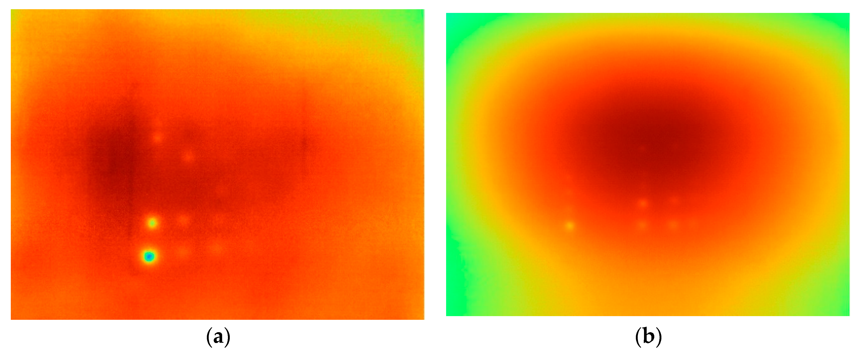
The results of IRT on both east and west sides in the morning (performed between 10:00 a.m. to 11:30 a.m.) and in the afternoon (performed between 2:00 p.m. to 3:30 p.m.) have been summarized in the Supplementary Material and Tables S1–S8. Figure 7 shows two thermograms as examples from these experiments. Note that the data in Tables S1–S8 were not necessarily collected on the same day; as a result, for most tests, there are considerable differences in the initial temperature between the morning tests and afternoon tests for a single heating–cooling combination. However, for each test, the IRT of the east and west sides was performed on the same day with a time difference of approximately 0.5 h. The defects are listed in each table in the Supplementary Material to show the defect detection improvement as the cycles increased to figure out the optimum or minimum number of heating–cooling cycles. The results shown in Tables S1–S8 indicate that, in most cases, the accuracy of completing five cycles is similar to six cycles. Therefore, performing five consequent heating–cooling cycles should be sufficient to detect the subsurface defects.
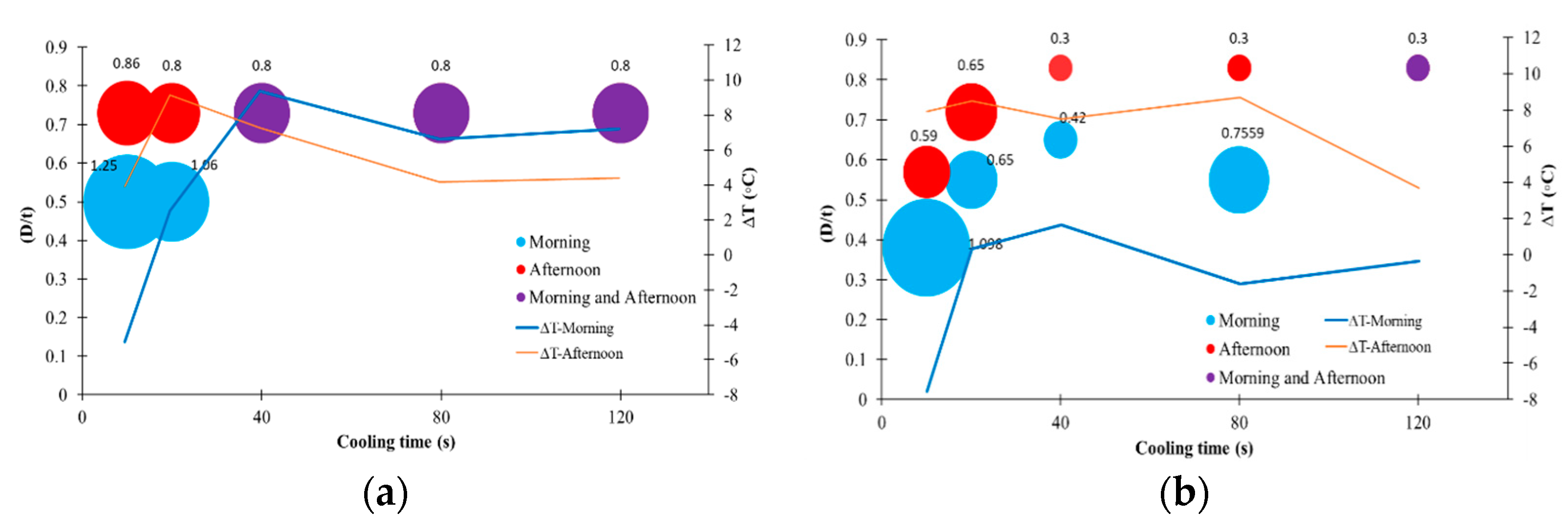
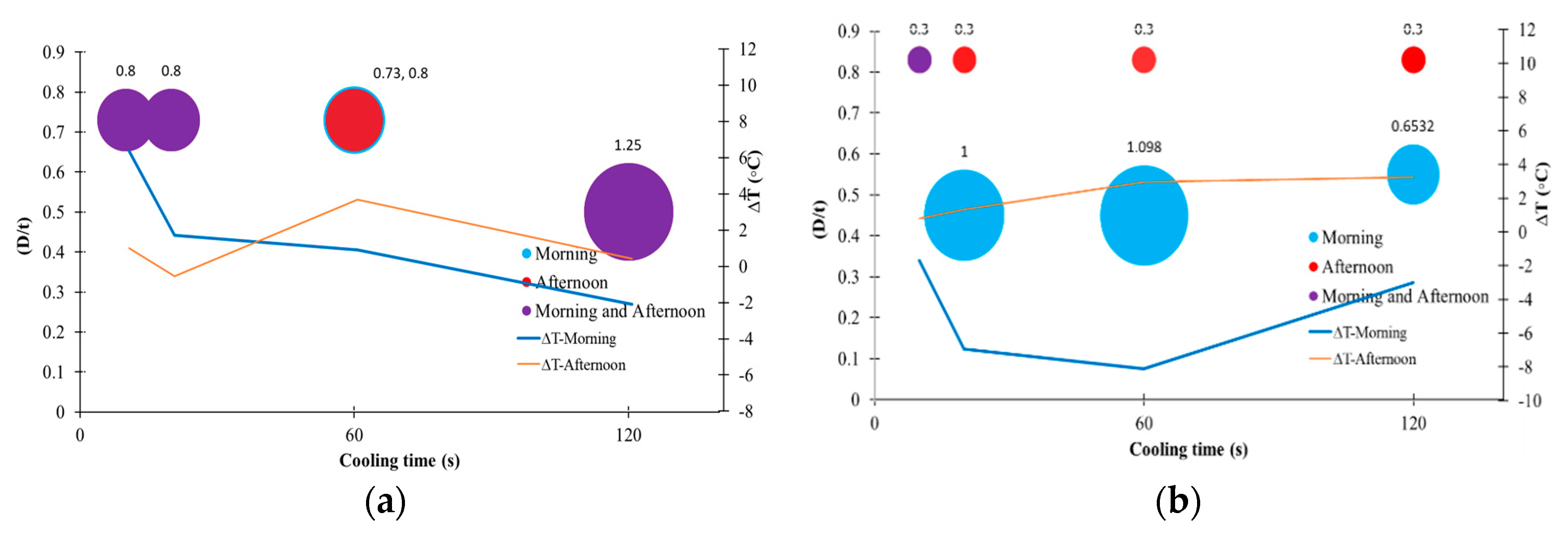
The preferred heating–cooling methodology is the one that optimizes detection accuracy while minimizing the time taken to perform the test. The highest detection accuracy can be defined as the ability to detect the smallest aspect ratio (AR) and the largest ratio of defect depth (D) to the wall thickness (t) (D/t). For this reason, the plots of the smallest detected AR versus the maximum D/t for different heating–cooling combinations at the final cycle (cycle #6) are shown in Figure 8, Figure 9, Figure 10 and Figure 11. The diameter of the bubbles in these figures represents the AR, and the AR values are printed next to each bubble. Therefore, the diameter of the bubbles can help to visually compare the performance of different heating–cooling combinations in detecting smaller defects. The results demonstrate that the maximum D/t is highly dependent on the initial ΔT. As the ΔT increases, regardless of being tested in the morning or afternoon, the maximum D/t increases. The reason is that, by having a high initial ΔT and by depositing additional external heat on the surface, the final thermal gradient on the thickness is higher compared to the time when the initial ΔT is negative. This is in good agreement with the previous experiments performed on the laboratory scale tank [8,9]. Therefore, as was mentioned in Section 3.1, the best time for performing IRT should be when there is a high positive ΔT, which can be achieved sometime between 9:00 a.m. to 6:00 p.m. The results indicate that the maximum D/t for the east side for all heating times is equal to 0.73 but, when the heating time was 20 s, it needed a larger positive ΔT to overcome this D/t threshold. Therefore, achieving a D/t of 0.73 when the heating time is 20 s is not guaranteed all the time, and it requires certain weather conditions; this indicates that 20 s of heating alone is not enough for deep heat penetration into the tank wall. Heating times greater than 30 s provide enough heat to penetrate deep enough for subsurface defect detection. By comparing the results of various heating durations on the east side of the tank, it is obvious that for any heating intervals larger than 30 s there is little improvement in the heat penetration depth in terms of the values of D/t. Therefore, for the east side, where the thickness of the wall was 12.7 mm (0.5 in), 30 s of heating should be sufficient to allow the heat to penetrate deeper into the tank wall. The smallest AR that could be detected for the east side when the heating times were 20 s, 30 s, 40 s, and 60 s were 0.86, 0.80, 0.80, and 0.73, respectively. This smallest detectable AR is not guaranteed for each heating duration because there is an interaction between the ΔT, D/t, and AR. In addition, the smallest detectable AR is controlled by the cooling duration in each cycle. If the cooling duration is long enough for that specific heating time, after completing all of the heating–cooling cycles, then not enough heat will be accumulated in the tank wall thickness to induce the required thermal gradient. On the contrary, if the cooling duration is too short, then the edges of the defects become saturated and there is insufficient contrast between the defect and the solid. Moreover, some other environmental parameters, such as relative humidity and wind speed, may affect the accuracy of the results. For instance, as experienced by the authors, on a windy day, the surface of the tank cools faster during the cooling phase due to heat loss from the surface exposed to the wind, so there is less heat penetration. Results shown in Figure 8, Figure 9, Figure 10 and Figure 11 indicate that the heating–cooling combinations of 30–90, 30–120, 40–40, 40–80, and 40–120 are the best options when the wall thickness is 12.7 mm (0.5 in), but the heating–cooling combination of 30–90 reduces the evaluation time.
For the west side, where the defects were created in the wall thickness of 19.1 mm (0.75 in), heating times of 40 s and 60 s resulted in comparable heat penetration into the wall thickness. The minimum AR detected was 0.79 for a heating time of 20 s and 0.30 for all other heating times. Therefore, 40 s should be selected as the shortest heating time to achieve the highest possible D/t and detect the smallest AR. When comparing the findings from the evaluation performed in the morning and the afternoon, it appears that the afternoon evaluation may provide greater accuracy by detecting a smaller AR for the west side while maintaining the same level of accuracy in detecting defects for the east side. This suggests that completing the evaluation in the afternoon will provide a higher possibility of detecting smaller defects for both the east and west sides. In addition, the smallest detectable AR highly depends on the cooling duration between the two heating cycles. Regardless of the cooling time, a heating time of 40 s or 60 s yields the same smallest detectable AR. Therefore, a heating–cooling combination of 40–40 or 40–80 can be applied in the field for five cycles as the shortest and most effective combination. The recommended heating–cooling combinations of 40–40 and 40–80 allow the inspector to heat one or two more spots and then come back to the first spot to start the next cycle which helps to speed up the evaluation process.
Comparing ΔT values reported for the 40 s heating duration, the highest D/t, and the smallest AR can be detected when ΔT > 4 °C (7.2 °F). If 0 °C (0 °F) < ΔT < 4 °C (7.2 °F), then the authors recommend increasing the heating duration to 60 s and following one of the combinations of 60–10, 60–20, or 60–60, which would allow for a greater heat deposit on the surface and therefore compensate for the lower ΔT. The combination of 60–60 allows the inspector to heat the next spot while performing IRT on the first spot which would be in the cooling phase, allowing for an optimized inspection time. If ΔT < 0 °C (0 °F), then the accuracy of the defect detection decreases dramatically. Therefore, the authors do not recommend performing IRT when ΔT is negative.

3.3. Impact of Camera Distance on the Defect Detection

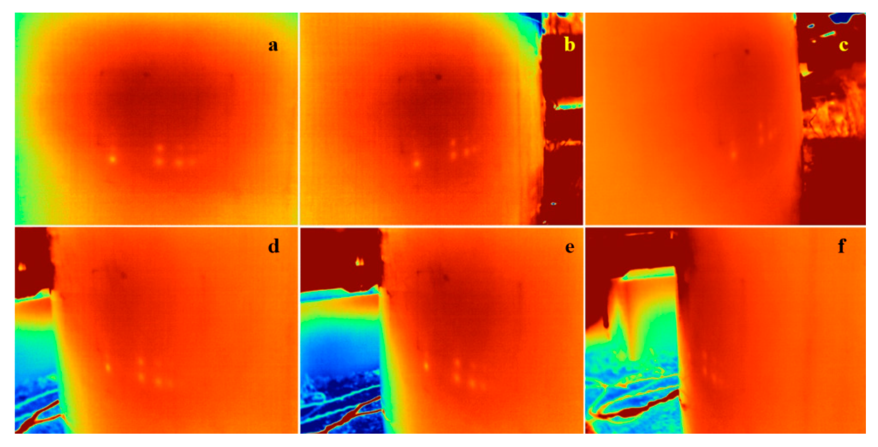
A concern about conducting the IRT in the field is the IR camera distance to the AST and its impact on the resolution and detection accuracy. In the field, it is not guaranteed that there will be enough space to evaluate the tank from the same distance that has been used in this study. Completing IRT using shorter distances is necessary when the ASTs are close to each other or when the tank is located next to a barrier. Figure 12 shows the thermograms captured from different distances at cycle #6 of the heating–cooling combination of 30–30 performed on the east side. The quantitative results are summarized in Table 7, which suggests that camera distances of 0.75 m to 1.3 m (2.5 ft to 4.3 ft) produce similar accuracies. A previous study found that a distance of 0.5 m to 1.5 m (1.6 ft to 4.9 ft) produced similar results [8], which agrees with the findings in this study. When the distance of the IR camera increases from 1.0 m to 2.0 m (3.3 ft to 6.6 ft), the smallest detectable AR and the maximum D/t both decrease by approximately 35%, while the inspected area increases by a factor of 3.8. When the distance of the IR camera increases from 1.0 m to 3.0 m (3.3 ft to 9.8 ft), the accuracy of the smallest detectable AR decreases by approximately 60% while the inspected area increases by a factor of 8.6. Therefore, the authors recommend using a camera distance of 0.5 m to 1.5 m (1.6 ft to 4.9 ft).

3.4. Impact of the Angle of View on the Defect Detection

The other factor that may affect the accuracy of the defect detection in IRT is the angle of view, defined here as the angle offset from perpendicular to the tank surface. Figure 13 shows a set of experiments ranging from 0° to 75° relative to the perpendicular to the tank surface. The defects detected in the directions 0° to 30° produce the most reasonable thermograms for defect detection, so the angle of view for inspection should not surpass 30°.

3.5. Impact of Heating Source Distance to the Tank on the Defect Detection

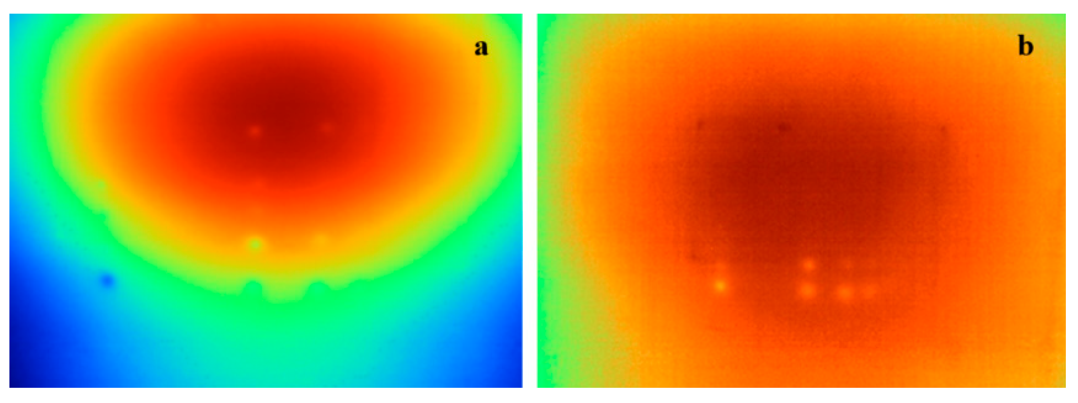
Similar to the concern about how the IR camera distance impacts the accuracy of defect detection, as discussed in Section 3.3, there is a concern about the distance of the external heating source to the tank wall. The thermogram in Figure 14 was produced by placing the heater very close to the tank wall surface at a distance of less than 10 cm (4 in). Such localized heating deposited more heat in a small area, which saturated the area under inspection and reduced the heat deposited in the adjacent areas. Therefore, when the heat source is too close to the object (i.e., the tank wall in this study), the induced thermal gradient in the area under study is not uniform, resulting in a poor defect detection. Thus, the authors recommend stacking as many external heat sources and increasing the distance of the heat source from the tank wall to cover the entire area under evaluation. Increasing the distance of the heating source to the tank wall causes a more uniform heat deposition, which helps to prevent heat diffusion on the surface. This results in better heat penetration into the tank wall in the area under evaluation, which consequently results in better defect detection.

3.6. Ultrasonic Testing (UT)

PAUT was previously shown to be very adept at detecting defects on a simulated tank in the laboratory under controlled conditions [8]. However, PAUT inspections of a full-scale tank yield significantly greater background noise, which is attributed to the signal attenuation and the fact that the interior of the tank is not necessarily smooth (e.g., some tanks have a wavy texture on the interior wall surface). In general, it was found that the shallower defects were more easily detected by PAUT. The only defect that could not be measured by PAUT was R1C6, which had a depth so small it could not be measured with traditional tools (i.e., calipers and pulse-echo UT). The defects surrounding R1C6, which were R1C5, R2C5, and R2C6, could all be measured using PAUT. As these three defects are the smallest in the set, the authors conclude that all other defects can also be measured using PAUT.
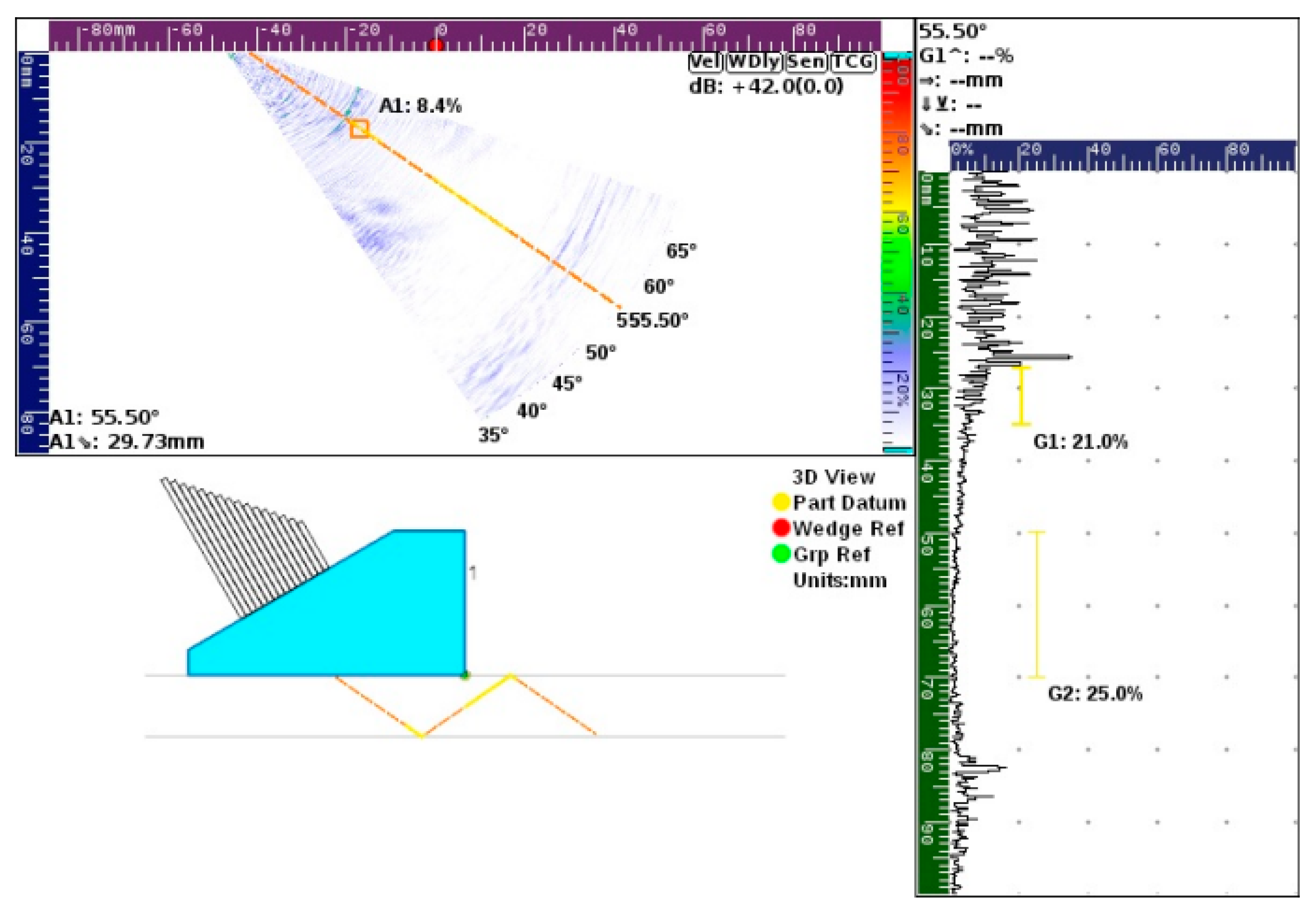
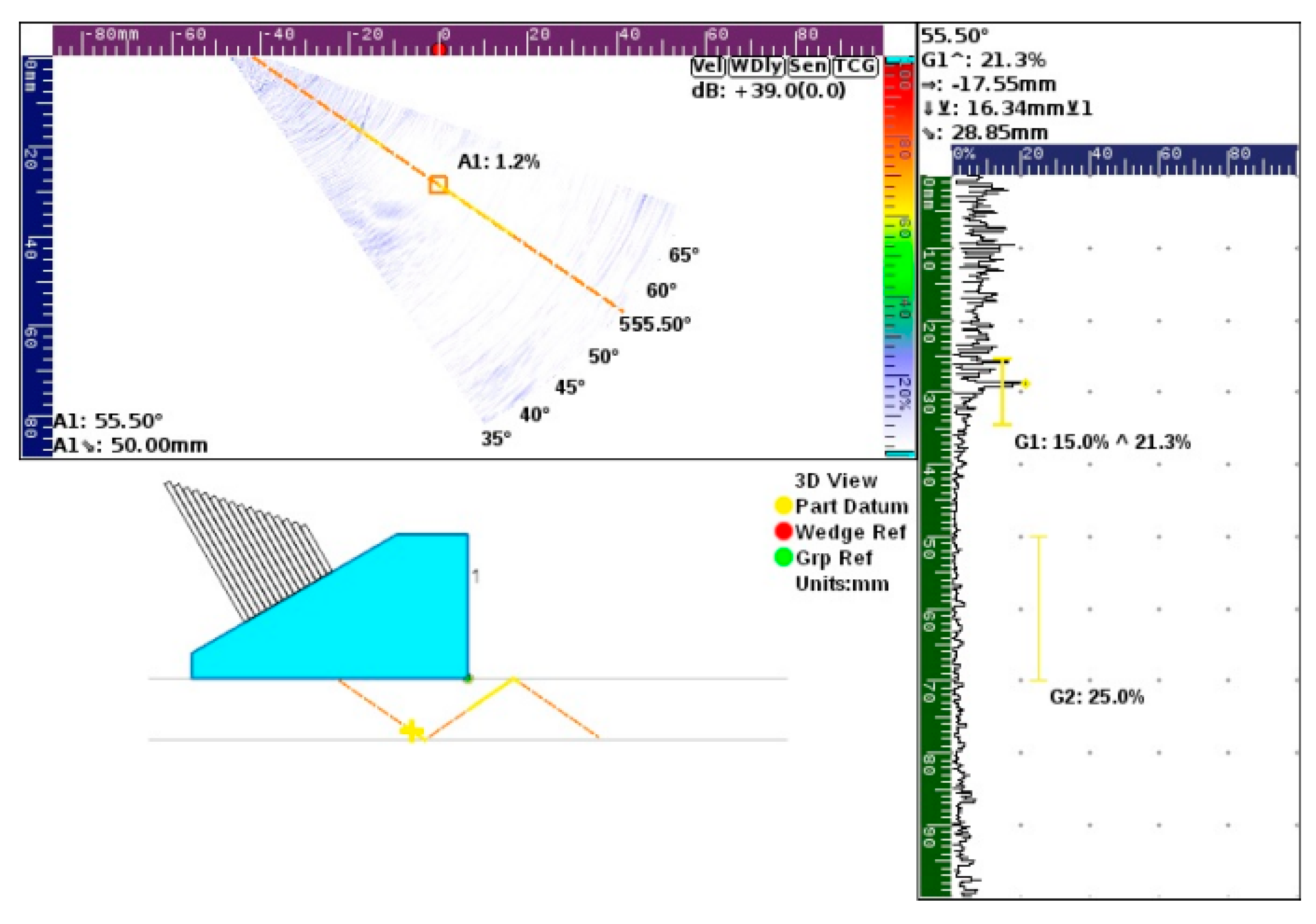
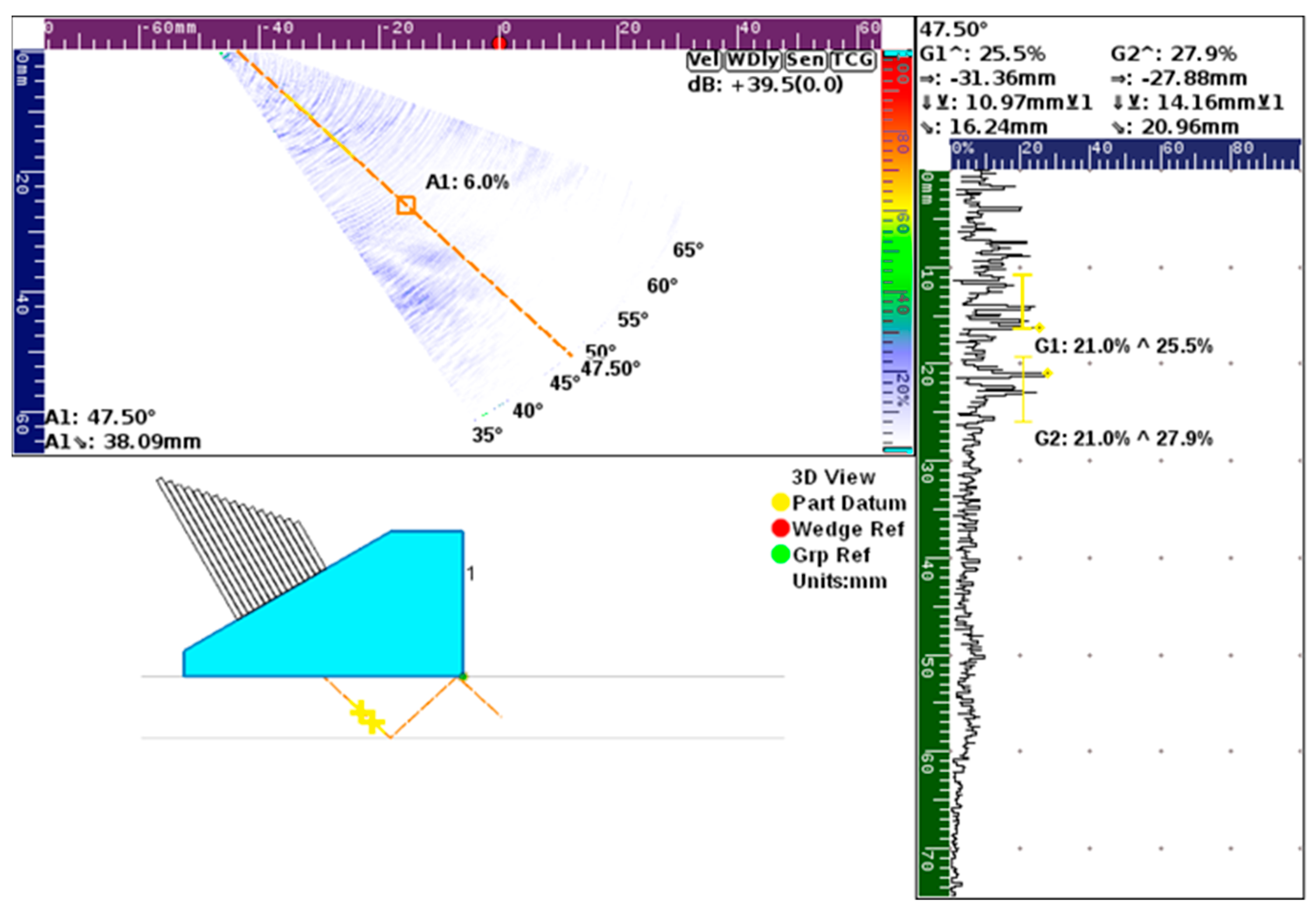
There were three types of results when using PAUT to find defects over locations where defects were known to be: (1) a confident result (Figure 15), where the returned signal strength was strong enough to easily distinguish from the background noise; (2) a less confident result (Figure 16) that returned a weaker signal strength but that was still distinguishable from the background noise, and (3) a returned signal strength indistinguishable from the background noise (Figure 17). A skilled, trained operator can distinguish a return signal from a defect in the third result type. When the phased array probe is moved back and forth over the location of a small defect, the return signal behaves differently from the background noise, which is how it can be distinguished.

3.7. Practical Guidelines for HDPE AST Integrity Evaluation

The performance of the HDPE tank depends on many parameters, such as the location (e.g., weather conditions and the number of freezing cycles experienced during winters), the liquid (e.g., the concentration of the liquid and type of the stored liquid), the frequency of the filling and emptying, the maintenance program, etc. Therefore, the frequency and interval between the inspections of an HDPE AST tank should be determined by its service history unless outstanding circumstances call for an earlier inspection. A tank’s service history can be obtained by reviewing the performance of a tank in a similar service, ideally at the same location and with the same material and capacity. The inspector, inspection company, or owner should develop detailed checklists that identify, record, and document all aspects of each inspection. To evaluate an HDPE AST, the authors propose the following inspection guideline:
  • Review prior formal and periodic inspections, and identify the locations that need closer inspection.
  • Visually inspect the AST and look for any abnormality or unusual signs, such as cracking, crazing, brittle appearance, holes, dents, and abrasions.
  • Visually check around the fittings, particularly focusing on the areas around the steel bolts. Check fittings, hoses, gaskets, and all connections for any signs of general corrosion (in steel bolts and gaskets), deterioration, or leaks. Note changes from the original design and installation information, if available.
  • Walk around the AST and look for any deformation, buckling, or distortion. Pay attention to where the upper section of the wall meets the lower section of the wall, which is usually waist height. This connection separates the thicker wall in the lower section from the thinner wall in the upper section. Compare changes from the current inspection with the last inspection report.
  • Look closely for signs of brittleness in the tank’s dome. Chemicals that produce fumes can cause the dome to oxidize and embrittle without being in direct contact with the brine solution. To avoid walking or standing on the dome surface, the evaluation of the dome should be completed by safety-certified personnel using lift equipment.
  • Investigate the base of the AST to make sure it rests on a firm and even base. Animals can burrow underneath the AST, causing the base to settle unevenly. Note changes from the original design and installation information, if available.
  • Use the IR camera without using the external heat source and walk around the AST to check for any anomalies that may interfere with the defect detection. If there is something on the external wall, wipe off the AST wall to remove any moisture and wait for at least 10 min until a uniform temperature forms on that area before starting the evaluation. In addition, pay attention to see if there is any leakage from the AST, especially close to fittings.
  • Power on the external heat source, and allow it to reach maximum power. Record the ambient temperature, relative humidity, and wind speed. Measure the temperature of the liquid inside the AST, and measure the AST wall temperature at different spots to calculate a representative ∆T (ΔT = Twall_surface − Tliquid).
    • If ∆T > 0, then IRT can be conducted. If the AST is located outdoors, then the best time frame for conducting the IRT evaluation is between 9:00 a.m. and 6:00 p.m., preferably between 2:00 p.m. and 6:00 p.m. ASTs located indoors can be inspected using IRT at any time of day.
    • If ∆T < 0, then do not proceed with IRT investigations.
  • Start the IRT experiment by selecting the heating–cooling combination according to the recommendations provided in Table 8.
  • Heat the first area, and move to heat the next area. Heating successive areas limit downtime. While one area is in the cooling phase, perform IRT. When the cooling cycle is complete for the first area, return to it and begin heating it again. Repeat this procedure for five cycles in each area, and perform an IRT observation during each cooling phase. Mark areas that have potential subsurface defects based on the IRT inspection.
  • Use ultrasonic instrumentation over the marked areas for a more detailed investigation. Move the PAUT probe vertically and diagonally in 15° angles left and right along the surface of the AST to detect subsurface defects. Measure the defect size and depth from the external surface.

3.8. Field Testing

The authors followed the guidelines mentioned in Section 3.7 to evaluate two in-service HDPE ASTs. The goal was to estimate the time needed to finish the evaluation of a single tank and to identify the field testing challenges. The information on each tank is summarized in Table 9. The wall thickness of the tanks was measured using a pulse-echo UT probe. The P-wave velocity of HDPE was estimated by measuring the temperature of the surface and the regression data from Ref. [9]. The first tank was empty, while the second tank was full of a brine solution. Both tanks were currently reported by the owner as being in “good condition”. Since the first tank was empty, the ∆T was assumed to be zero, and therefore the heating–cooling cycle of 60–60 was chosen for this tank. For the second tank, the external wall temperature was 30 °C (86 °F), and the brine inside the tank had a temperature of 26.1 °C (79.0 °F); therefore, the heating–cooling cycle of 40–120 was chosen. For both tanks, the bottom 1.3 m (4.27 ft) all around the tanks were examined.
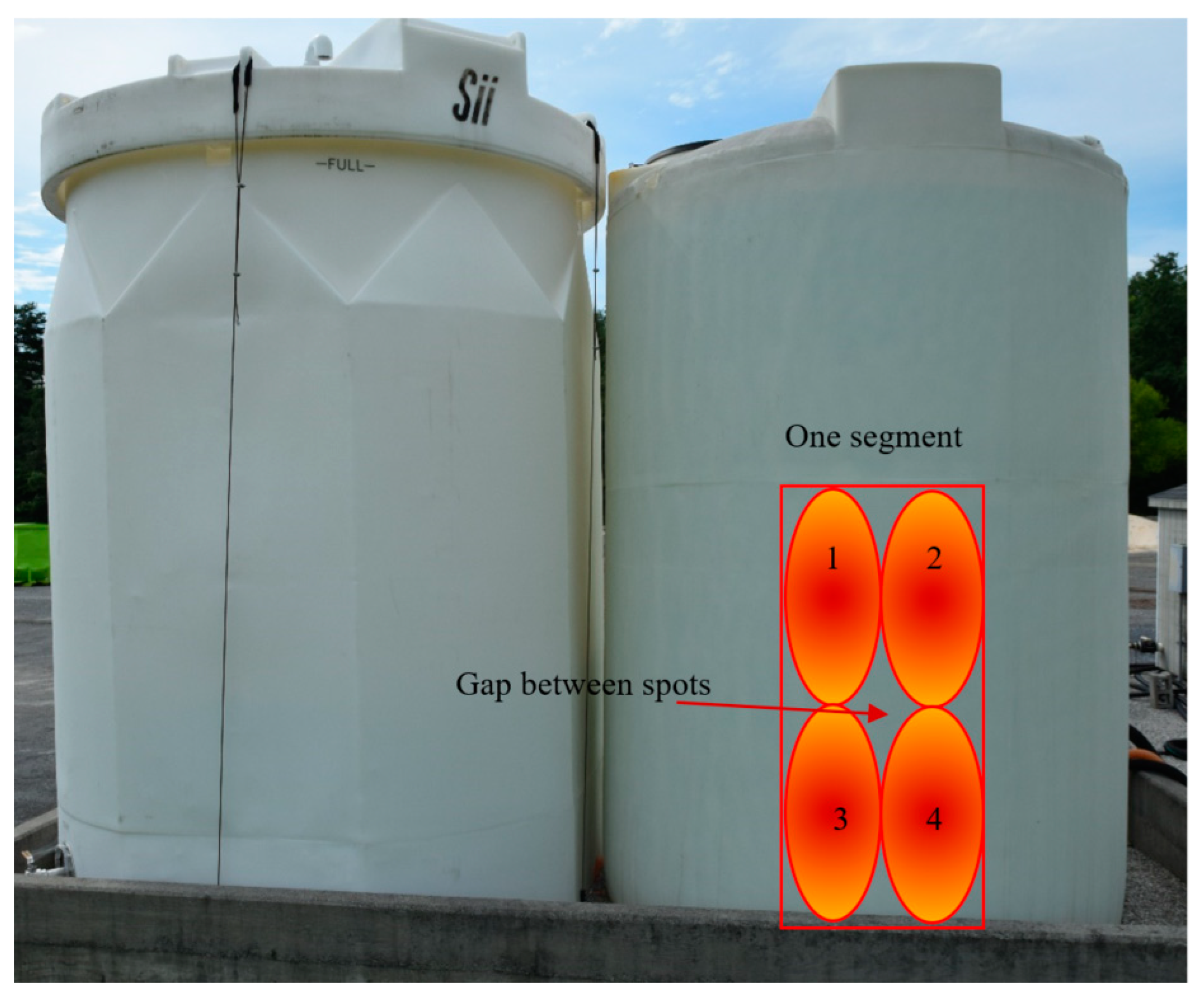
Due to the hoses connected to the fittings and outlets, it was impossible to directly heat the fittings and evaluate the fittings in one step. Therefore, the fittings were heated twice: once from the left side and once from the right side. The circumference of the tank was divided into nine segments, as shown in Figure 18, with each segment consisting of four spots. While the first spot was cooling, the second spot was heated for 60 s on the first tank to complete 60–60 cycles. On the second tank, when Spot #1 was in the cooling phase, Spots #2, #3, and #4 were heated for 40 s each to complete 40–120. Each segment had an average size of 1.25 m2 ± 0.22 m2 (13.5 ft2 ± 2.4 ft2).
For the first tank, each segment required approximately 20 min to complete the IRT investigation. Therefore, an estimated 180 min is needed, but the actual inspection took 375 min to complete due to moving the heating source and other equipment, switching laborers and inspectors, replacing batteries, etc. For the second tank, each segment required approximately 13.3 min to complete the IRT investigation; therefore, an estimated 120 min is needed, but the actual inspection took 285 min to complete only the IRT inspection. Comparing the total inspection time for both tanks shows that completing the IRT on a full tank reduces the time needed for the evaluation by approximately 25%, due to having a positive thermal gradient induced by the liquid inside the tank. Looking at the long practical time required to complete IRT on a single tank shows that it is better to start the evaluation from the east side in the morning and finish it on the west side in the afternoon. One can reduce the inspection time by increasing the number of stacked heaters to cover larger areas and therefore reduce the number of segments required for completing the inspection of an AST.

3.9. IRT Challenges for the Field Evaluation of HDPE ASTs

Although IRT is a great technique for defect detection in many industries, it has some challenges for the inspection of HDPE ASTs. Some of the challenges found during this study are listed below:
  • IRT can be used only as an indicator of the defects’ existence and does not provide information about the location and depth of the defects. Supplementary evaluation with UT can further assess the location and depth of defects. This is also true when using IRT on other materials.
  • Defect detection accuracy highly depends on ambient weather conditions.
  • IRT is not able to detect small defects (AR < 0.3) or very deep defects (D/t > 0.83).
  • IRT is not able to detect non-leaking cracks propagated from the internal side of the AST towards the surface. This has been discussed in more details in Ref [9].
  • IRT is labor intensive and requires personnel to heat areas in different cycles.
  • IRT is time-consuming for HDPE ASTs, due to the material’s low thermal conductivity. The operator should be prepared with multiple charged batteries for the equipment.
  • Using various IR cameras from various manufacturers or various models produced by the same manufacturer could affect the accuracy of defect detection.
  • Water droplets due to rain, fog, or other activities close to the AST can interfere with defect detection.
  • Because many sites will contain a number of ASTs that need to be inspected, this task can become tedious. Therefore, to expedite the evaluation process, the inspection can be limited to the lower sections of the AST (i.e., waist height and below) where failures are most frequently reported.
  • IRT can be completed on the lower (i.e., waist-high and below) sections of the AST without the need for any additional equipment. If there is an accident or a concern close to the top of the AST, then the evaluation process may be challenging in the absence of hydraulic lifters or cranes.
  • The IRT equipment needs to have access to electrical power. A portable generator is useful in the field.
  • Appropriate electrical access for IRT is challenging to obtain. The heaters recommended for performing IRT have a large current draw and will trip most conventional circuits. It is recommended either to use two separate electrical sources or to use a sufficiently capable portable generator.
  • The heaters used for IRT can reach extremely high temperatures. Careful consideration must be taken to ensure that the operator is properly insulated from the heat generated by the infrared heaters.
  • To prevent fire or electrical hazards, it is recommended to turn off the heaters for 10 min every 20 min or for 15 min every 30 min. Aside from proper insulation, this is the best way to keep the heaters within a comfortable heat range for the operators. The authors recommend using stacked infrared heaters, such as those being used for paint curing, in order to reduce these hazards, keep the operator safe, and deposit a more uniform temperature on the area under study.
  • Heating around the fittings is challenging and causes non-uniform heat deposits. Hoses connected to the outlets prevent the application of heat on the surface behind them. Moreover, heating these hoses may inadvertently cause damage to the hoses and gaskets.
  • Since an operator is moving the heater, it is not guaranteed that exactly the same area heated during one cycle is being heated in the next cycle. There is likely to be a gap between the heated spots, as shown in Figure 18. Therefore, it is possible that some sections of the tank may be missed during the inspection.
  • Discolorations, stains, superficial scratches, and information tags interfere with defect detection, which may reduce the speed of evaluation by numerous false detections.

3.10. UT Challenges for the Field Evaluation of HDPE ASTs

While UT techniques are particularly useful for steel infrastructure inspection, using PAUT in the field for evaluating HDPE ASTs has some challenges as listed below:
  • Due to the AST wall curvature, all sides of the probe cannot be in contact with the AST wall, and therefore, the water leaks from the water probe. This can be solved by using a more powerful water pump. Note that the pump used in this study had an uninhibited flow rate of 23 L/min (6 gal/min); however, when tubing was used to attach the pump to the water wedge probe, the flow rate fell to 0.9 L/min (0.25 gal/min). In order to overcome this issue, a pump with a minimum uninhibited flow rate of 38 L/min (10 gal/min) is recommended to fill the water probe reservoir faster than the leakage discharge.
  • Completing the PAUT on the upper section of the AST is difficult and requires a more powerful water pump to pump up the water to that elevation.
  • The water pump requires electricity, so a portable generator may be required in the field.
  • The water pump requires a consistent source of water, which can be accomplished by using a 5 gal (19 L) bucket, although larger volumes of water may be needed for longer inspections.
  • The measurement should be done by moving the probe up and down or by an angle of 15° compared to the vertical line. This reduces the water leaks from the water probe and helps obtain better results. Moving the probe in angles greater than 15° from the vertical line will result in more leakage due to the AST wall curvature.
  • Completing PAUT on the cone-shaped outlets is impossible. In such cases, using traditional pulse-echo UT is recommended.
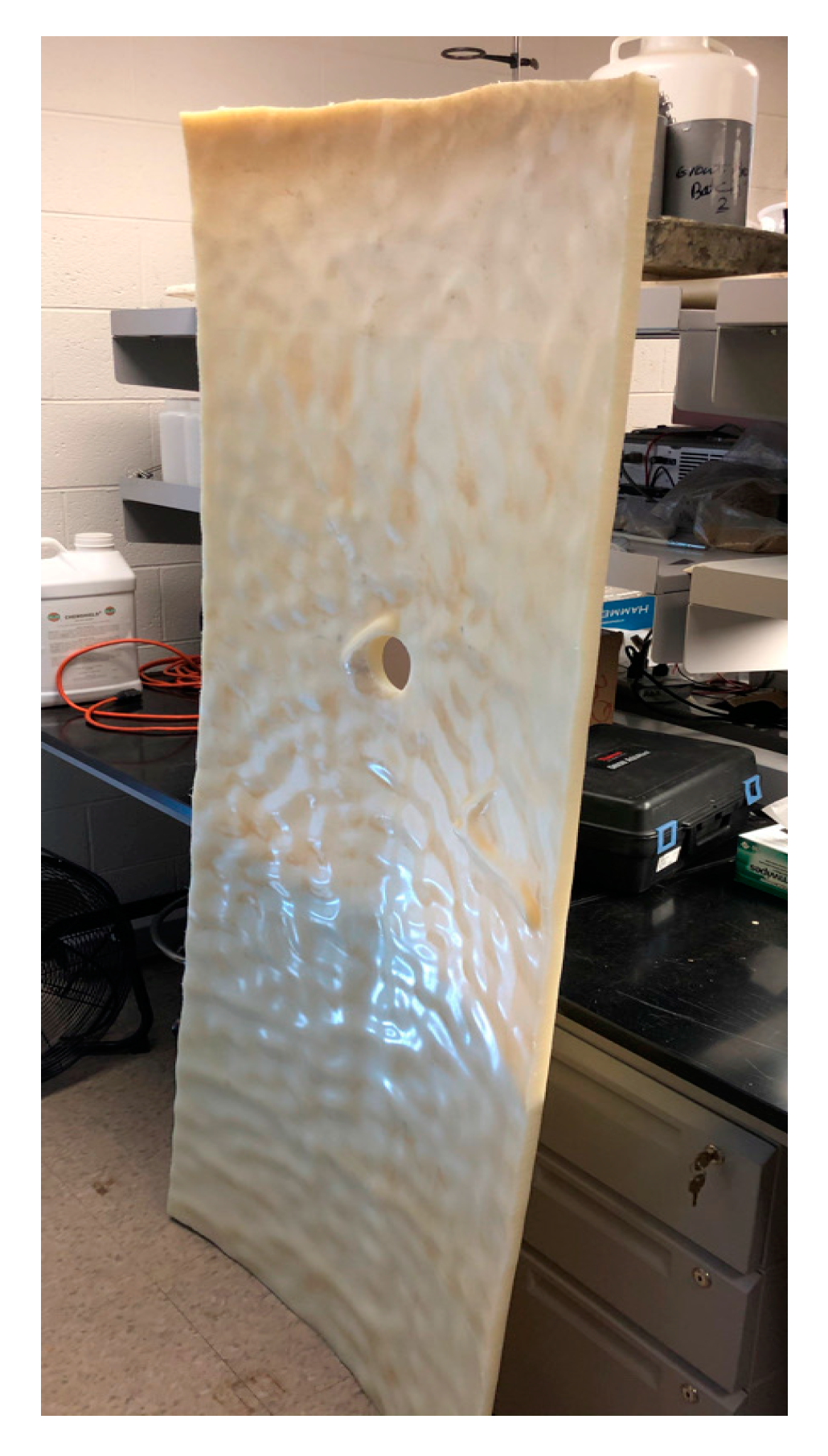
  • During the manufacturing of some HDPE ASTs, the interior of the AST can have a wavy texture, as shown in Figure 19. This texture will increase the background noise and can interfere with the results. High amounts of waviness inside the AST may reduce the effectiveness of UT techniques since the wavy texture will scatter the ultrasonic waves. If the investigator does not have enough experience with evaluating HDPE ASTs, then the waviness could mistakenly be reported as a defect. In such cases, the UT is still useful since it can detect areas where the wall thickness is less than the thickness mentioned in the AST specifications.
  • UT methods, both pulse-echo UT and PAUT, are dependent on the temperature of the element being inspected. If UT is performed after IRT, then the UT equipment must be recalibrated to the new material temperature to generate accurate results. If it is desired to avoid recalibration, then UT can be performed either before IRT or after sufficient time has elapsed to allow the material to return to the ambient temperature. Likewise, UT could be performed on a different day than IRT.
  • The liquid inside the AST causes background noise in the returned signals, which may block some defect signal peaks. However, a skilled UT operator can differentiate the background noise to detect defects as small as 4.4 mm (0.17 in).

4. Conclusions

In this work, the effectiveness of employing infrared thermography (IRT) and ultrasonic testing (UT) techniques for evaluating high-density polyethylene (HDPE) liquid storage tanks was investigated. IRT was conducted using heating–cooling cycles of varying durations. The initial thermal gradient (ΔT) that existed on the tank wall was measured for every single experiment as one of the largest impacts on evaluation accuracy. Phased array ultrasonic testing (PAUT) was taken into consideration because it requires access to just one side of the tank and enables the inspection of liquid-filled tanks. The following general conclusions can be drawn from this study:
  • The interaction of sample geometry, initial thermal gradient, defect location, and defect aspect ratio will impact the accuracy of IRT in detecting subsurface defects in HDPE ASTs.
  • The distance of the camera to the tank, the angle of view, the heating source power, and the distance of the heating power to the tank will impact the accuracy of the IRT measurements.
  • The best time for conducting IRT is on sunny days and between 9 a.m. to 6 p.m. Since the evaluation of the tank is time-consuming, the evaluation can be started from the east side in the morning and completed on the west side in the afternoon.
  • Completing the IRT evaluation in the afternoon (after 2:30 p.m.), will provide a higher probability of detecting smaller defects for both the east and west sides.
  • If ΔT < 0 °C (0 °F), then the accuracy of the defect detection diminishes dramatically. Therefore, it is not recommended to perform IRT if this condition exists.
  • When the thickness of the tank is 12.7 mm (0.5 in) and ∆T > 6 °C (10.8 °F), 30 s of heating for five consequent intervals should be sufficient to allow the heat to penetrate the tank wall. The combination of 30–90 (30 s heating with 90 s cooling) is recommended when the thickness of the tank is 12.7 mm (0.5 in).
  • When the thickness of the tank is 19.1 mm (0.75 in) and ∆T > 4 °C (7.2 °F), the heating–cooling combinations of 40–40, 40–80, or 40–120 are recommended.
  • The recommended distance of the IR camera to the tank is between 0.5 m to 1.5 m (1.6 ft to 4.9 ft) and the recommended angle of view is between 0° to 30° relative to the direction perpendicular to the tank wall.
  • In addition to IRT, PAUT can be utilized to examine HDPE ASTs in greater detail. PAUT was able to detect defects as small as 4.4 mm (0.17 in) in diameter in this study.
  • The massive liquid inside the tank, the attenuation of sound in HDPE, and the waviness of the tank wall interior will increase the background noise in PAUT investigations and reduce the capability of defect detection and measurement by UT.

Supplementary Materials

The following supporting information can be downloaded at: https://www.mdpi.com/article/10.3390/app13031396/s1, Tables S1–S8.

Author Contributions

Conceptualization, A.B. and A.S.B.; Methodology, A.B. and A.S.B.; Formal Analysis, A.B.; Investigation, A.B., T.Q.T., Y.L., M.D., M.S.S., M.M.D. and A.H.; Data Curation, A.B., T.Q.T., Y.L., M.D., M.S.S., M.M.D. and A.H.; Writing—Original Draft Preparation, A.B., T.Q.T., M.D., M.S.S. and M.M.D.; Writing—Review and Editing, A.B., M.M.D. and A.S.B.; Visualization, A.B., T.Q.T. and M.M.D.; Supervision, A.S.B.; Project Administration, A.S.B.; Funding Acquisition, A.S.B. All authors have read and agreed to the published version of the manuscript.

Funding

This research was funded by Virginia Transportation Research Council (VTRC), Project 117955.

Data Availability Statement

The data presented in this study are available on request from the corresponding authors.

Acknowledgments

The authors thank Lewis Lloyd at Virginia Transportation Research Council (VTRC) for his help during this study. The authors would like to thank David Mokarem and Brett Farmer at Virginia Tech for their assistance with the decommissioned HDPE AST. The authors appreciate the support from Fred Whitford from Purdue University for providing a booklet from his experiences on tank failures. The authors thank James Helvey for his assistance in moving the decommissioned AST from Virginia Department of Transportation (VDOT) facilities to Virginia Tech and for assisting with locating field testing sites.

Conflicts of Interest

The authors declare no conflict of interest.

References

  1. Wypych, G. Handbook of Polymers, 2nd ed.; ChemTec Publishing: Toronto, ON, Canada, 2016. [Google Scholar]
  2. Whitford, F.; Salomon, S.; Oltman, D.; Obermeyer, J.; Hawkins, S.; Pearson, M.; Overstreet, B.; Titus, M.; Lambert, S.; Hawkins, M. Poly Tanks for Farms and Businesses: Preventing Catastrophic Failures, Report PPP-77. 2008. Available online: https://www.extension.purdue.edu/extmedia/ppp/ppp-77.pdf (accessed on 13 August 2021).
  3. Cornell, J.; Baker, M. Catastrophic Tank Failures: Highlights of Past Failures along with Proactive Tanks Designs. US EPA Fourth Biennial Freshwater Spills Symposium, Cleveland. 2002. Available online: https://archive.epa.gov/emergencies/content/fss/web/pdf/cornellpaper.pdf (accessed on 13 August 2021).
  4. Whitford, F.; Hawkins, S.; Holland, L.; Carr, B.; Meredith, D.; Ileleji, K.; Campbell, D.; Gentry, L.; Hamby, L.; Roach, M. Blessing, Aboveground Petroleum Tanks: A Pictoral Guide, Report PPP-73. 2007. Available online: https://www.extension.purdue.edu/extmedia/PPP/PPP-73.pdf (accessed on 13 August 2021).
  5. Myers, P. Aboveground Storage Tanks; McGraw-Hill Education: New York, NY, USA, 1997. [Google Scholar]
  6. Atherton, W.; Ash, J. Review of failures, causes and consequences in the bulk storage industry. In Proceedings of the 2nd Annual Liverpool Conference, Built Environment and Natural Environment; 2007. Available online: https://citeseerx.ist.psu.edu/viewdoc/download?doi=10.1.1.489.7637&rep=rep1&type=pdf (accessed on 28 September 2021).
  7. Spicer, M.; Hagglund, F.; Troughton, M. Development and validation of an automated ultrasonic system for the non-destructive evaluation of welded joints in thermoplastic storage tanks. In Proceedings of the 11th European Conference on Non-Destructive Testing, Prague, Czech Republic, 6–11 October 2014. [Google Scholar]
  8. Behravan, A.; Dejong, M.M.; Brand, A.S. Laboratory Study on Non-Destructive Evaluation of Polyethylene Liquid Storage Tanks by Thermographic and Ultrasonic Methods. Civileng 2021, 2, 823–851. [Google Scholar] [CrossRef]
  9. Behravan, A.; Tran, T.; Hernandez, A.; DeJong, M.; Brand, A. Evaluating the integrity of high-density polyethylene (HDPE) storage tanks. J. Mater. Civ. Eng. 2022, in press. [Google Scholar]
  10. Barreira, E.; de Freitas, V. Evaluation of building materials using infrared thermography. Constr. Build. Mater. 2007, 21, 218–224. [Google Scholar] [CrossRef]
  11. Lourenço, T.; Matias, L.; Faria, P. Anomalies detection in adhesive wall tiling systems by infrared thermography. Constr. Build. Mater. 2017, 148, 419–428. [Google Scholar] [CrossRef]
  12. Kamińska, P.; Ziemkiewcz, J.; Synaszko, P.; Dragan, K. Comparison of Pulse Thermography (PT) and Step Heating (SH) Thermography in Non-Destructive Testing of Unidirectional GFRP Composites. Fatigue Aircr. Struct. 2019, 2019, 87–102. [Google Scholar] [CrossRef]
  13. Lagüela, S.; Díaz-Vilariño, L.; Roca, D. Infrared thermography: Fundamentals and applications. In Non-Destructive Techniques for the Evaluation of Structures and Infrastructure; CRC Press: Boca Raton, FL, USA, 2016. [Google Scholar] [CrossRef]
  14. Maldague, X.; Marinetti, S. Pulse phase infrared thermography. J. Appl. Phys. 1996, 79, 2694–2698. [Google Scholar] [CrossRef] [Green Version]
  15. Pitarresi, G. Lock-In Signal Post-Processing Techniques in Infra-Red Thermography for Materials Structural Evaluation. Exp. Mech. 2013, 55, 667–680. [Google Scholar] [CrossRef]
  16. Mulaveesala, R.; Tuli, S. Implementation of frequency-modulated thermal wave imaging for non-destructive sub-surface defect detection. Insight-Non-Destr. Test. Cond. Monit. 2005, 47, 206–208. [Google Scholar] [CrossRef]
  17. Yang, R.; He, Y.; Mandelis, A.; Wang, N.; Wu, X.; Huang, S. Induction Infrared Thermography and Thermal-Wave-Radar Analysis for Imaging Inspection and Diagnosis of Blade Composites. IEEE Trans. Ind. Inform. 2018, 14, 5637–5647. [Google Scholar] [CrossRef]
  18. Duan, Y.; Huebner, S.; Hassler, U.; Osman, A.; Ibarra-Castanedo, C.; Maldague, X.P. Quantitative evaluation of optical lock-in and pulsed thermography for aluminum foam material. Infrared Phys. Technol. 2013, 60, 275–280. [Google Scholar] [CrossRef]
  19. Foudazi, A.; Donnell, K.M.; Ghasr, M.T. Application of Active Microwave Thermography to delamination detection. In Proceedings of the 2014 IEEE International Instrumentation and Measurement Technology Conference, Montevideo, Uruguay, 12–15 May 2014; IEEE: Piscataway, NJ, USA, 2014; pp. 1567–1571. [Google Scholar] [CrossRef] [Green Version]
  20. Fierro, G.P.M.; Calla’, D.; Ginzburg, D.; Ciampa, F.; Meo, M. Nonlinear ultrasonic stimulated thermography for damage assessment in isotropic fatigued structures. J. Sound Vib. 2017, 404, 102–115. [Google Scholar] [CrossRef] [Green Version]
  21. Di Tuccio, M.C.; Ludwig, N.; Gargano, M.; Bernardi, A. Thermographic inspection of cracks in the mixed materials statue: Ratto delle Sabine. Heritage Sci. 2015, 3, 10. [Google Scholar] [CrossRef] [Green Version]
  22. Ibarra-Castanedo, C.; Sfarra, S.; Ambrosini, D.; Paoletti, D.; Bendada, A.; Maldague, X. Diagnostics of panel paintings using holographic interferometry and pulsed thermography. Quant. Infrared Thermogr. J. 2010, 7. [Google Scholar] [CrossRef]
  23. Cheng, L.; Tian, G.Y. Surface Crack Detection for Carbon Fiber Reinforced Plastic (CFRP) Materials Using Pulsed Eddy Current Thermography. IEEE Sens. J. 2011, 11, 3261–3268. [Google Scholar] [CrossRef]
  24. Schmerr, L.W., Jr. Fundamentals of Ultrasonic Phased Arrays; Solid Mechanics and Its Applications; Springer: Cham, Switzerland, 2015; Volume 215. [Google Scholar]
  25. Saleh, B.; Silevitch, M.; Miller, E.; Karl, C.; Vélez-Reyes, M.; Goodman, J.; Roysam, B.; Rappaport, C.; Martinez, J.; McKnight, S.; et al. Introduction to Subsurface Imaging; Cambridge University Press: Cambridge, UK, 2009. [Google Scholar] [CrossRef] [Green Version]
  26. Frederick, C.; Porter, A.; Zimmerman, D. High-Density Polyethylene Piping Butt-Fusion Joint Examination Using Ultrasonic Phased Array. J. Press. Vessel Technol. 2010, 132, 051501. [Google Scholar] [CrossRef]
  27. Qin, Y.; Shi, J.; Zheng, J.; Hou, D.; Guo, W. An Improved Phased Array Ultrasonic Testing Technique for Thick-Wall Polyethylene Pipe Used in Nuclear Power Plant. J. Press. Vessel Technol. 2019, 141. [Google Scholar] [CrossRef]
  28. Guo, W.-C.; Shi, J.; Hou, D.-S. Research on phased array ultrasonic technique for testing butt fusion joint in polyethylene pipe. In Proceedings of the 2016 IEEE Far East NDT New Technology & Application Forum (FENDT), Nanchang, China, 22–24 June 2016; pp. 1–5. [Google Scholar] [CrossRef]
  29. Zheng, J.; Shi, J.; Guo, W. Development of Nondestructive Test and Safety Assessment of Electrofusion Joints for Connecting Polyethylene Pipes. J. Press. Vessel Technol. 2012, 134, 021406. [Google Scholar] [CrossRef]
  30. Miao, C.; Qin, Y.; Guo, W.; An, C.; Ling, Z.; Chen, Z. Ultrasonic Phased Array Inspection With Water Wedge for Butt Fusion Joints of Polyethylene Pipe. In Proceedings of the ASME 2019 Pressure Vessels & Piping Conference, San Antonio, TX, USA, 14–19 July 2019. [Google Scholar] [CrossRef]
  31. Hagglund, F.; Robson, M.; Troughton, M.; Spicer, W.; Pinson, I. A novel phased array ultrasonic testing (PAUT) system for on-site inspection of welded joints in plastic pipes. In Proceedings of the 11th European Conference on Non-Destructive Testing, Prague, Czech Republic, 6–11 October 2014. [Google Scholar]
  32. Thorpe, N.; Acebes, M.; Wylie, D.; Troughton, M.; Gilmour, O.; Roy, O.; Benoist, G.; Dweik, R. Ultrasonic phased array non-destructive testing and in-service inspection system for high integrity polyethylene pipe welds with automated analysis software. In Proceedings of the 12th European Conference on Non-Destructive Testing, Gothenburg, Sweden, 11–15 June 2018. [Google Scholar]
  33. Egerton, J.S.; Lowe, M.J.S.; Huthwaite, P.; Halai, H.V. Ultrasonic attenuation and phase velocity of high-density polyethylene pipe material. J. Acoust. Soc. Am. 2017, 141, 1535–1545. [Google Scholar] [CrossRef] [Green Version]
  34. Mažeika, L.; Šliteris, R.; Vladišauskas, A. Measurement of velocity and attenuation for ultrasonic longitudinal waves in the polyethylene samples. Ultragarsas 2010, 65, 12–15. [Google Scholar]
  35. Adachi, K.; Harrison, G.; Lamb, J.; North, A.M.; Pethrick, R.A. High frequency ultrasonic studies of polyethylene. Polymer 1981, 22, 1032–1039. [Google Scholar] [CrossRef]
  36. Arnold, N.D.; Guenther, A.H. Experimental determination of ultrasonic wave velocities in plastics as functions of temperature. I. Common plastics and selected nose-cone materials. J. Appl. Polym. Sci. 1966, 10, 731–743. [Google Scholar] [CrossRef]
  37. Carlson, J.E.; van Deventer, J.; Scolan, A.; Carlander, C. Frequency and temperature dependence of acoustic properties of polymers used in pulse-echo systems. In Proceedings of the 2003 IEEE Symposium on Ultrasonics, Honolulu, HI, USA, 5–8 October 2003; pp. 885–888. [Google Scholar] [CrossRef]
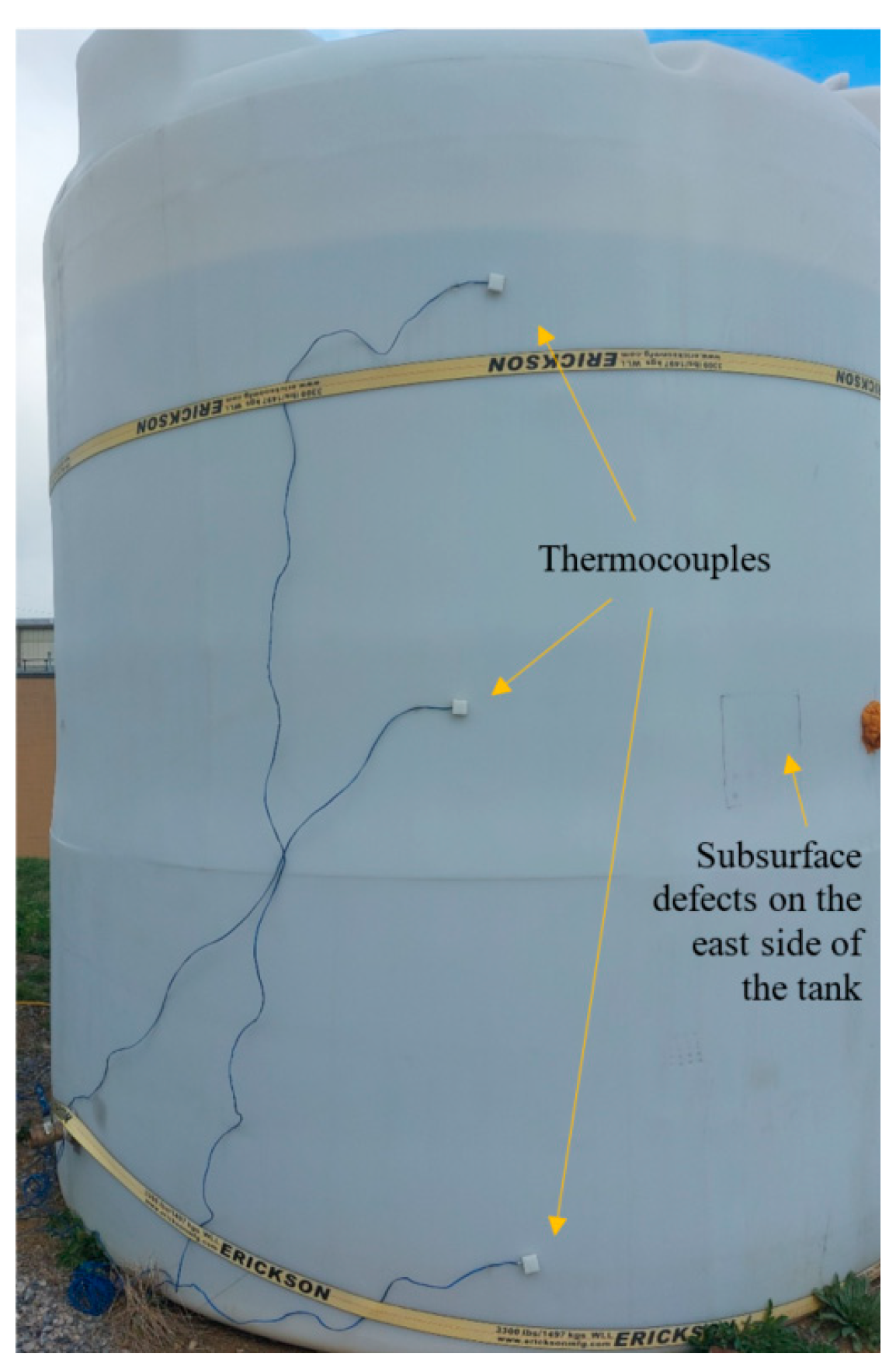
Figure 1. The configuration of the tank under study and the arrangement of the installed thermocouples.
Applsci 13 01396 g001
Figure 2. Configuration of the defects created inside the tank wall: (a) defects on the internal east side of the tank; (b) defects on the internal west side of the tank.
Applsci 13 01396 g002
Figure 3. The non-uniform temperature on the tank (picture was taken in the afternoon when the sun was on the west side).
Applsci 13 01396 g003
Figure 4. Temperature change on the tank wall at three different elevations of the top, middle, and bottom from two different sides of east and west measured via attached thermocouples: (a) at 10:30 a.m. and (b) at 4:30 p.m.
Applsci 13 01396 g004
Figure 5. Temperatures of the HDPE tank, water, and ambient on two cloudy days during winter, measured via attached thermocouples.
Applsci 13 01396 g005
Figure 6. Temperatures of the HDPE tank, water, and ambient on two sunny days during (a) summer and (b) winter measured via attached thermocouples.
Applsci 13 01396 g006
Figure 7. Two examples of the thermograms obtained from (a) cycle #6 of the heating–cooling combination of 40–80 performed on the east side, and (b) cycle #6 of the heating–cooling combination of 60–60 performed on the west side.
Applsci 13 01396 g007
Figure 8. Characterization of the defects detected when the heating time was 20 s on the (a) east side and (b) west side.
Applsci 13 01396 g008
Figure 9. Characterization of the defects detected when the heating time was 30 s on the (a) east side and (b) west side.
Applsci 13 01396 g009
Figure 10. Characterization of the defects detected when the heating time was 40 s on the (a) east side and (b) west side.
Applsci 13 01396 g010
Figure 11. Characterization of the defects detected when the heating time was 60 s on the (a) east side and (b) west side.
Applsci 13 01396 g011
Figure 12. Thermograms captured during a single cycle with camera distances of (a) 0.75 m (2.5 ft), (b) 1.0 m (3.3 ft), (c) 1.3 m (4.3 ft), (d) 2.0 m (6.6 ft), (e) 2.30 m (7.5 ft), and (f) 3.00 m (9.8 ft).
Applsci 13 01396 g012
Figure 13. Thermograms captured from different angles of view: (a) 0°, (b) 30°, (c) 60°, (d) −30°, (e) −60°, and (f) −75°.
Applsci 13 01396 g013
Figure 14. Impact of close heating on the defect detection (a) localized and non-uniform heating (b) uniform heating.
Applsci 13 01396 g014
Figure 15. An example of a confident signal return detected using PAUT.
Applsci 13 01396 g015
Figure 16. An example of a less confident signal return detected using PAUT.
Applsci 13 01396 g016
Figure 17. Return signal indistinguishable from background noise detected using PAUT.
Applsci 13 01396 g017
Figure 18. Image of two in-service HDPE ASTs with configuration of one segment consisting of four heated spots labeled.
Applsci 13 01396 g018
Figure 19. The waviness of the interior wall of an HDPE AST.
Applsci 13 01396 g019
Table 1. Heating and cooling duration combinations considered for each cycle during IRT measurement.
Heating Time (s)Cooling Time (s)
201020406080100120
301020306090120-
4010204080120--
60102060120---
Table 2. IR camera properties reported by the manufacturer.
Detector resolution640 × 480 (307,200 pixels)
Field of view34 °H × 24 °V
Temperature measurement range−20 °C to 1000 °C (−4 °F to 1832 °F)
Accuracy±2 °C or 2% (whichever is greater)
Thermal sensitivity (NETD)≤0.05 °C at 30 °C target temp (50 mK)
Frame rate60 Hz
Infrared spectral band7.5 μm to 14 μm (long wave)
Table 3. Settings of the IR camera used for the study.
Emissivity0.78
Background23 °C (73 °F)
Transmission100%
Range−20 °C to 100 °C (−4 °F to 212 °F)
Table 4. Settings used for wave velocity calibration with pulse-echo UT.
Voltage mono100 V
Mono pulse damping50 ohms
Pulse typeSpike
Probe diameter 12.7 mm (0.5 in)
Reference amplitude80.0%
Range path100 mm (4 in)
Travel modeHalf path
Acquired frequency 100 MHz
Table 5. Characteristics of the defects shown in Figure 2 created on the internal east side of the tank (wall thickness, t = 12.7 mm = 0.5 in).
DefectsDiameter (mm)C1C2C3C4C5C6
Depth 1AR 2D/t 3DepthARD/tDepthARD/tDepthARD/tDepthARD/tDepthARD/t
R11.6N/A 4N/AN/AN/AN/AN/AN/AN/AN/AN/AN/AN/AN/AN/AN/AN/AN/AN/A
R24.42.651.640.216.410.680.518.260.530.659.830.440.7711.480.380.90N/AN/AN/A
R34.82.541.880.207.490.640.599.440.500.7410.990.4300.8711.710.410.92N/AN/AN/A
R45.23.861.340.301.224.230.106.290.820.5010.680.480.8411.340.450.89N/AN/AN/A
R56.42.542.500.206.011.060.474.721.340.377.920.800.6211.440.550.90N/AN/AN/A
R67.92.033.910.162.872.770.236.341.250.509.210.860.7311.130.710.88N/AN/AN/A
R712.71.27100.106.302.020.506.272.020.499.281.370.7310.461.210.82N/AN/AN/A
1 Depth from the external surface (D) (mm); 2 AR: aspect ratio which is equal to the ratio of defect diameter (d) to the defect depth (D) (AR = d/D); 3 D/t: Ratio of the defect depth (D) to the wall thickness (t); 4 Could not obtain reliable measurements of depth due to small defect size.
Table 6. Characteristics of the defects shown in Figure 2 created on the internal west side of the tank (wall thickness, t = 19.1 mm = 0.75 in).
DefectsDiameter
(mm)
C1C2C3C4C5C6
Depth 1AR 2D/t 3DepthARD/tDepthARD/tDepthARD/tDepthARD/tDepthARD/t
R11.6N/A 4N/AN/AN/AN/AN/AN/AN/AN/AN/AN/AN/AN/AN/AN/AN/AN/AN/A
R24.410.400.420.559.470.460.5012.510.350.6614.590.300.7717.350.250.9118.270.240.96
R34.815.850.300.833.141.520.162.302.070.127.190.660.3813.870.340.7310.030.470.53
R45.21.982.610.106.530.790.347.900.650.4112.300.420.6516.140.320.8517.610.290.92
R56.44.341.460.236.321.000.339.070.700.4810.820.590.5712.480.510.6616.040.400.84
R67.97.231.100.384.231.880.226.261.270.3310.500.760.5513.100.610.6916.610.480.87
R712.73.973.200.216.262.030.336.671.910.358.531.490.4513.630.930.7217.030.750.89
1 Depth from the external surface (D) (mm); 2 AR: aspect ratio which is equal to the ratio of defect diameter (d) to the defect depth (D) (AR = d/D); 3 D/t: Ratio of the defect depth (D) to the wall thickness (t); 4 Could not obtain reliable measurements of depth due to small defect size.
Table 7. Accuracy of defect detection at different distances.
Distance (m (ft))Maximum D/tMinimum ARArea under Evaluation (m2 (ft2))
0.75 (2.5)0.730.800.15 (1.6)
1.0 (3.3)0.730.800.26 (2.8)
1.3 (4.3)0.730.800.44 (4.7)
2.0 (6.6)0.501.250.98 (10.6)
2.3 (7.5)0.501.251.66 (17.9)
3.0 (9.8)0.502.012.22 (23.9)
Table 8. Guideline for selecting the heating–cooling durations.
Wall Thickness (mm (in.))∆T (°C (°F))Heating–Cooling Durations (s)
12.7 (0.5)∆T > 6 (10.8) 30–90
12.7 (0.5)6 (10.8) > ∆T ≥ 0 (0)60–20 or 60–60
12.7 (0.5)0 (0) > ∆TDo not perform the evaluation
19.1 (0.75)∆T > 4 (7.2)40–40 or 40–80 or 40–120
19.1 (0.75)4 (7.2) > ∆T ≥ 0 (0)60–20 or 60–60
19.1 (0.75)0 (0) > ∆TDo not perform the evaluation
Table 9. Information on the two HDPE ASTs tested in the field.
Tank Capacity
(gal (L))
Tank Age (Years)Tank TypeWall Thickness
(mm, (in))
Tank Diameter
(m, (ft))
Empty/Full
5000 (18,900)12Single wall19.1 (0.75)2.60 (103)Empty
5000 (18,900)17Single wall19.1 (0.75)2.60 (103)Full
Disclaimer/Publisher’s Note: The statements, opinions and data contained in all publications are solely those of the individual author(s) and contributor(s) and not of MDPI and/or the editor(s). MDPI and/or the editor(s) disclaim responsibility for any injury to people or property resulting from any ideas, methods, instructions or products referred to in the content.