Article

Functionally Graded Additive Manufacturing: Bridging the Gap between Design and Material Extrusion

1
Department of Mechanical and Industrial Engineering, Norwegian University of Science and Technology, Richard Birkelands vei 2b, 7491 Trondheim, Norway
2
Department of Civil, Environmental and Architectural Engineering, University of Padova, Via Venezia 1, 35131 Padova, Italy
3
Department of Management and Engineering, University of Padova, Stradella S. Nicola, 3, 36100 Vicenza, Italy
*
Author to whom correspondence should be addressed.
Appl. Sci. 2023, 13(3), 1467; https://doi.org/10.3390/app13031467
Submission received: 20 December 2022 / Revised: 12 January 2023 / Accepted: 19 January 2023 / Published: 22 January 2023
(This article belongs to the Section Additive Manufacturing Technologies)

Abstract

:

Featured Application

This paper proposes a methodology allowing any designer to be able to produce multi-material parts.

Abstract

Nowadays, the use of 3D printing is becoming a key process for on-demand and customized manufacturing. One of the most flexible 3D printing techniques is fused deposition modeling (FDM), where the combination of multiple materials was recently introduced. A quantum leap in part design is possible by integrating local variations between materials that allow for expanded functionality to be built into a single part. Therefore, the process of co-extrusion and material mixing is becoming more and more popular. The process of management and design of the engineered part are still complicated, and there are no commercially available tools that follow the process from design to production of these highly engineered products. This paper proposes a methodology to fill this gap and allow any designer to be able to produce multi-material parts by editing a G-code (computer numerical control programming language) with engineered gradients for FDM technology. More specifically, the proposed approach is based on the modification of the G-code according to a volumetric model describing the local combination of two or more materials. This original aspect allows for a wide extension of the current software capabilities. To explain and test the method, a simple test case was investigated, in which two components of an earphone are consolidated and developed gradually by combining polylactic acid and thermoplastic polyurethane. The results show the effectiveness of the proposed approach within the limits of the material coextrusion additive manufacturing process.

1. Introduction

Additive manufacturing (AM) is a manufacturing process that creates parts by adding materials layer-by-layer. Unlike traditional manufacturing processes, AM only adds materials where it is required, thus reducing material waste. Furthermore, AM can fabricate parts with extremely complex geometry.
Aside from homogeneous materials, the fabrication of functionally graded materials (FGMs) using AM technologies has recently been studied [1,2]. Unlike traditional composite materials that are made by combining two dissimilar materials, either homogeneous mixtures or joined materials, to produce improved properties, FGMs are characterized by a compositional gradient of one material into another [3]. Often, in composites there are sharp transitions between dissimilar components, which can cause high-stress concentrations and even delamination under complex loading conditions [4]. Conversely, in FGM, the sharp interface is replaced by a gradient interface that is a mixture of both components, and it gradually changes inside the component. It follows that 3D printing of complexly shaped heterogeneous objects with continuously graded properties, such as mechanical property, hysteresis, and variable magnetic strength, can be realized by gradually changing the spatial volume fraction distribution of different constituents.
The concept of FGM was first proposed in the 1980s in Japan. At that time, heat-resistant ceramics and tough metals were applied to the FGM design for a thermal barrier, with a temperature difference higher than 1000 K [5]. Nowadays, FGMs with other types of functions can be used in many areas, such as aerospace, biomedical engineering, sensors, and energy [6,7].
As mentioned, recent progresses in AM have allowed the production of parts using FGMs, through a process known as functionally graded additive manufacturing (FGAM) [8]. Among the AM process, as confirmed by the literature, fused deposition modeling (FDM) is a promising technology for FGAM. Indeed, FDM is one of the most popular processes, due to the possibility of processing cost-effective and non-toxic materials and making products at a lower cost, allowing for different transition types in FGMs, such as interlocking shapes, coextrusion, and mixing, where different fractions of materials are combined in the hot-end and flow in the same nozzle [9,10,11,12,13]. Nonetheless, FGAM needs an effective toolpath control that is based on a triptych “materials-product-manufacturing” approach [14]. The procedure for the manufacturing of FGAM parts is similar to the one employed in traditional AM, involving solid model generation using CAD (computer-aided design), slicing, conversion of the CAD file into STL file format (or other appropriate data exchange file format), verification of the STL data, determination of optimal orientation for the printing, generation of support material, toolpath calculation, fabrication, and post-processing. The main distinction is that FGAM prioritizes the description and assignment of material distribution in the design domain, which can be assigned based on functional requirements, adopting different representation schemes [15,16].

Current FGAM Software Limitations

At present, the standard file formats used in the field of AM are the STL and OBJ file formats, which are triangular facet models represented by polygonal meshes. These file formats describe only the surface geometry and contain no material or volumetric property information. In addition, various data exchange formats may be suitable for the production of FGAM components, including AMF (additive manufacturing format), FAV (fabricatable voxel), SVX (simple voxels), and 3MF (3D manufacturing format). These file formats, beyond a defined geometric description, can include information about the material gradient and micro-scale physical properties [1,15,17]. However, at present, slicing software tools, also known as computer-aided manufacturing (CAM) software, do not support the description of graded materials, and therefore, it is not possible to process the information stored in those files into the computer numerical control programming language (G-code) required for manufacturing FGAM parts.
For this reason, new methodologies for slicing, evaluating, and manufacturing FGAM are required. New software for FGAM processes should include the capability to control the density and the allocation of material fractions based on the functional requirements for the generation of FGAM geometric models. Some novel approaches for handling those new features, required to produce functionally graded components, were proposed by researchers over the last years. For example, Richards and Amos [18] proposed a computational approach that uses CPPN (compositional pattern producing network) encoding a scalable algorithm using NEAT (neuroevolution of augmented topologies) to embed functional morphologies and macro-properties of physical features using multi-material FGAM through voxel-by-voxel descriptions according to its cartesian (x, y, and z) coordinates [19]. The conversion to a voxel model from a common geometric format (i.e., an STL file) for FGAM is computationally demanding and difficult to achieve, especially when dealing with highly refined details [20]. To overcome this issue, Richard and Amos [18] introduced an alternate design-supporting system to represent material-geometry-topology, with a volumetric texture map using voxels models that are algorithmically generated. Modifications can be performed manually on voxels, and then compiled back into the texture description.
Still, these methods are not straightforward and require a lot of time and knowledge to be implemented. Moreover, implementations on commercial design software are not available for design or manufacturing, which are indispensable in industrial applications.
This work aims to provide an original methodology for the fabrication of FGAM with limited computational effort, avoiding sophisticated and proprietary file formats for data exchange of FGM geometric models. Starting from a surface model and a material distribution, the paper is focused on handling the G-code in FDM coextrusion according to a volumetric model. The methodology is then tested on headphones, in which a hard case and a soft earpad are consolidated in a single part with graded stiffness.

2. The Proposed Method

The adoption of FGMs increases the designers’ freedom, enlarging the range of material properties that can be used in the same part, and allowing for the improvement of the performance of the products. Based on functional and aesthetical requirements, the surface model and the distribution of the material are usually obtained by following the design approaches proposed in the literature, which consider among other aspects, material properties, compatibility, and process capabilities [14,21,22].
Starting from the design outputs, i.e., a surface model (CAD model) and a material distribution, a simple and versatile methodology is proposed, allowing the manufacturing of FGM parts by FDM coextrusion. The proposed method consists of 3 main steps, highlighted in Figure 1:
  • G-code computing (CAM);
  • volumetric modeling;
  • G-code editing.
Then, the FDM process is set up by leveling the bed, loading the modified G-code, adjusting the process parameters, such as temperature, flow, and speed, and starting the manufacturing process. To complete the procedure, the part is removed from the platform, and, if necessary, it is post-processed to remove supports and defects, and to improve the surface finish.

2.1. G-Code Computing

As mentioned, the surface model is obtained in the design for functional and aesthetical requirements. Usually, in mechanical design the parts are made of homogeneous materials, and it is sufficient to represent only the surface of the components, which can be achieved by different representation schemes, such as boundary representation or constructive solid geometry in a CAD environment. Analogously, in the proposed approach it is possible to define the surface model by standard approaches. This model is exported in an STL file format, that is the de facto standard for AM data exchange [15,23].
The model is imported into the CAM software, positioned, and oriented with respect to the manufacturing platform. Then, the process parameters, such as layer thickness, speed, temperature, slicing strategies, and infill density, are set, and then the G-code is computed as in a standard FDM workflow. The G-code is the language used by the computer numerical control (CNC) to drive the machine tools during the manufacturing process. This language holds the manufacturing instructions, such as the tools movements and speed.

2.2. Volumetric Modeling

The functional requirements were also used to establish the distribution of the materials in the part, which is considered to define the volumetric model. The literature proposes some representation schemes for volumetric modeling, such as octree, polyhedral mesh, trivariate NURBS (non-uniform rational B-Spline), and implicit functions [15]. In this study, a voxel-based volumetric model is selected, due to its diffusion and simple implementation. Numeric values representing some properties in the three-dimensional space (e.g., density, materials fractions, and color) can be assigned to the voxel data structure according to the position of the unit volume (voxel) in the space [24,25,26,27]. To convert a surface model into a set of voxels, a process called voxelization is needed, where the resolution depends on the voxel size [27,28]. The properties of the voxels can be assigned to the voxel centroids. A regular point cloud can be considered as the centroid of voxels, and consequently, can be adopted as a voxel model data structure. The information describing the model properties is stored in a matrix C ¯ , with N rows and W columns, where each row defines the coordinates of a point, i.e., the voxel centroid and its properties, (xp, yp, zp, info1, info2, info3, …, and infoW-3) with potentially up to W-3 information for each voxel. Simpler data structures report only a list of properties, for example, the origin of the model, the spacing among points, and the number of points along each axis. Using a data structure available in CAD software, it is possible to export a cloud of points with colors adopting the RGB format, where each one of the three primary colors, i.e., red, green, and blue, are described by a value ranging from 0 to 255. It follows that it is possible to export the point cloud containing the desired material information by the attribution of the material property to a chosen color. Specifically, the point color information, e.g., the red channel, can be associated with the material fraction (MF) of X (equal to 1-MF of Y), reparametrized in the range 0–255, where X and Y represent two materials. For example, RGB = (255, 0, and 0) means 100% of X, RGB = (0, 0, and 0) means 100% of Y, and RGB = (63, 0, and 0) means 25% of X and 75% of Y. Defining a total fraction to each color channel (e.g., 30% for the R and G channels and 40% for the B channel), other couples of materials can be assigned to the channels G and B. Alternatively, the MF of a single material can be assigned to each channel. Analogously, using the RGBA color model (red, green, blue, and alpha channels), it is possible to assign the density to the alpha channel (transparency), which can be used to establish the extrusion amount, as previously proposed in the literature, for manufacturing graded lattice structures [29].

2.3. G-Code Editing

According to the computer numerical control programming language (G-code), the required fraction of each material is obtained by simultaneously controlling the amount of material pushed by each extruder. Adopting the Marlin firmware, the material percentage is coded into the G-code by the commands M163 and M164. The former sets the mutual amount of each material, whereas the latter assigns the mixing to a virtual extruder [30], such as:
  • M163 S0 P0.65
  • S1 P0.35
  • S5,
which means that the tool number 5 is set to be 65% of material in the left channel and 35% of material in the right channel. To call the n-virtual tool, it is necessary to introduce the line Tn in the right position of the G-code listing, where n is the number of the tool (5 in the example, i.e., T5) [31].
To allow a graded variation of composition in the x-y plane, the previously obtained G-code is manipulated by a Python script that divides the initial toolpath into shorter segments. The endpoints of the new segments are stored in a matrix ( P ¯ ) with M rows and 3 columns (xt, yt, and zt), which are the new toolpath points. The information describing the material properties stored in the matrix C ¯ (volumetric model) is finally attributed to each point of the matrix P ¯ . This is conducted by employing the k-nearest neighbourhood (KNN) algorithm that allows finding the nearest points of the matrix P ¯ for each point of the matrix C ¯ . The output is a matrix P c ¯ with M rows and W columns (xt, yt, zt, info1, info2, info3, …, and infoW-3) of the ordered points forming the previous toolpath, but with the addition of material information for each segment. Care must be taken when using the voxel model, considering the actual position and orientation of the part in the manufacturing platform. Finally, the G-code is edited via the segment endpoints, stored in the matrix P c ¯ , and the commands (M163 and M164) for the material fraction of each segment. This routine was implemented in Python programming language.

3. Results and Discussion

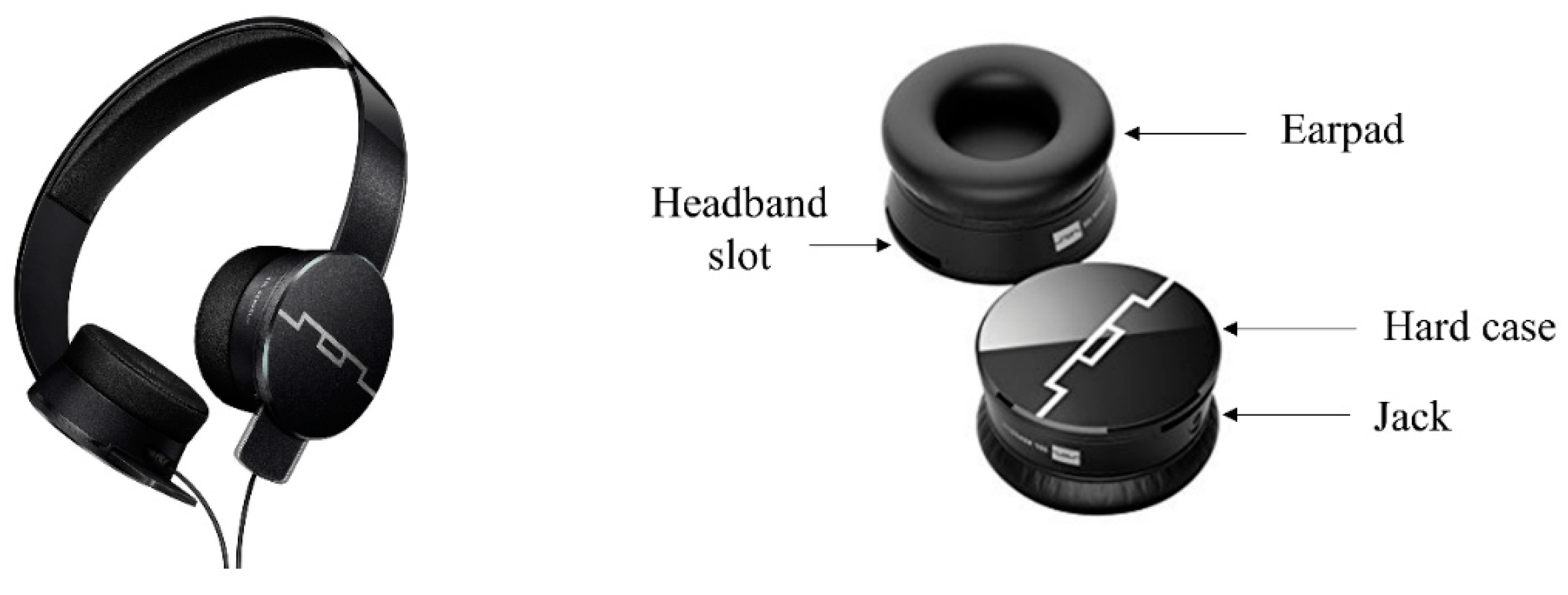
To explain the method and test the proposed workflow, the approach is applied to a part designed with a graded material distribution. The model was inspired by the SOL Republic model Plus HD headphone and is shown in Figure 2, in which it is possible to identify the main parts: a hard case and a soft ear pad.
The shape of the earphone component was geometrically modeled in Rhinoceros 7 (Robert McNeel and associates) using NURBS surfaces. The parts, i.e., the hard case and the soft earpad, were consolidated into a single component. The surface model was meshed, i.e., discretized by adjacent planar polygons with three or four edges that which approximate the NURBS surface, and was exported as an STL file adopting the following parameters:
  • Tolerance: 0.01 mm;
  • Maximum aspect ratio: 6;
  • Minimum edge length: 0.0001 mm;
  • Maximum distance, edge to surface: 0.01 mm;
  • Maximum edge length/angle and minimum initial grid quads: 0.
Figure 3 shows the model with the main dimensions and a longitudinal section to show the internal detail.
Two materials were selected: PLA Extrafill (polylactic acid) for the rigid portions, and FlexFill TPU 98A (thermoplastic polyurethane) for the compliant areas, both supplied by Fillamentum [32]. Table 1 shows the main properties of the materials selected in this work. The choice of this pair of materials is due to the wide range of properties that can be reached by varying the material fraction and the compatibility between them, while maintaining rather similar process conditions that are easy to achieve with standard equipment, as confirmed by the literature [11,33,34,35].
The material distribution and CAM parameters (e.g., infill density and number of perimeters) are closely related to the local stiffness of the part, and they can be defined by functional requirements in the design process. In this work, linear variations of the material fraction along the z-axis are assumed, as shown in Figure 4, where the material distribution is visualized by the color of the model. To prevent clogging issues during manufacturing, it could be useful to avoid material fractions (MFs) less than 5% and over 95%. Theoretical MF variation can be introduced in every direction, but at this first stage, the study was limited to the z-direction, to neglect the delay effects due to the volume of the material in the melting chamber, which will be studied in future works.

3.1. CAM Processing

The shape and MFs have been described by different sources. The shape is described by a mesh as an input for the CAM processing. The G-code is generated by the open-source software Slic3r [36], starting from the geometry following a conventional workflow. Table 2 summarizes the selected manufacturing process parameters that consider the range of manufacturing parameters suitable for both PLA and TPU.

3.2. Volumetric Modeling

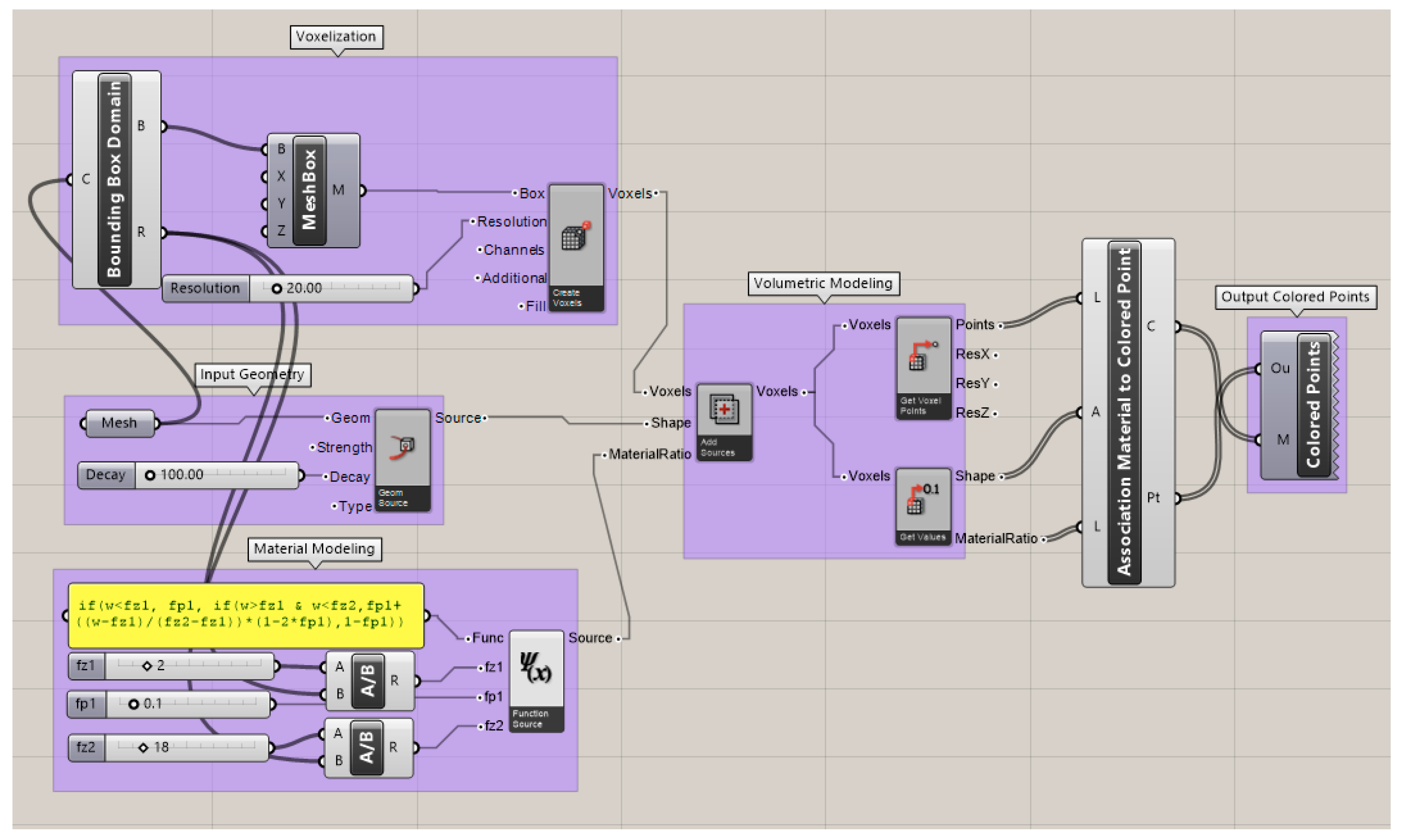
The volumetric information was handled in Grasshopper, a visual programming tool that runs within Rhinoceros 7 (Robert McNeel and associates), by means of a definition that includes the Monolith addon [37], where the voxel model is based on the normalized coordinates. Figure 5 presents the implemented definition, organized as a workflow.
The MF can be described with an equation via arithmetic operators, mathematical functions, and logical operators. The cartesian coordinates are denoted by x , y , z , if absolute or u , v , w if relative. Moreover, u , v , w are normalized within the voxelization volume.
The MF for the headphone is described by a mathematical function as follows (see the “Material Modeling” group in Figure 5):
i f   w < f z 1 :   M F = f p 1 e l i f   f z 1 < w < f z 2 :   M F = f p 1 + ( w f z 1 f z 2 f z 1 ) · ( 1 2 · f p 1 ) e l s e :   M F = 1 f p 1
where f z 1 and f z 2 define the upper and lower bounds of the gradient along the z-direction. Outside this height, a constant MF is maintained, respectively, f p 1 and f p 2 = 1 f p 1 ; w is the normalized height and ranges between zero and one.
The information regarding the MF and the shape is used as an input for generating the voxel field: a voxel 3D grid is created according to the overall dimensions of the headphone (bounding box) and the resolution, allowing for the construction of a generic voxel class (“Voxelization” in Figure 5); the properties of each voxel are assigned according to the voxel centroid and the MF computed in the same position (“Volumetric Modeling” in Figure 5).
Then, the voxels information is mapped to a colored points cloud by a cluster (“Association Material to Colored Point” in Figure 5): for each voxel, a centroid point has been created; if the centroid is inside the headphone model, the information referred to this material has been associated with an RGB color model. The result of this process is a colored point cloud. The points information is then exported as a text document (.txt).
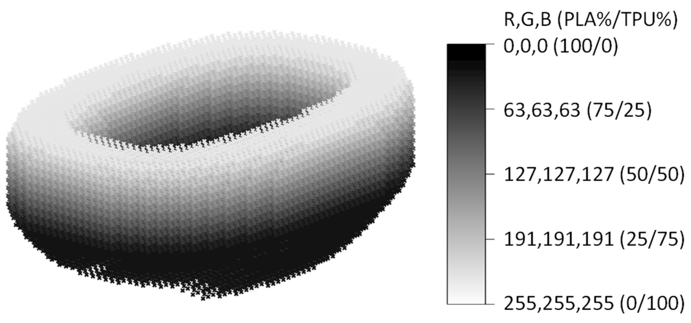
Assuming fp1 = 0.1, fz1 = 15/37.6, and fz2 = 35.6/37.6 (37.6 mm is the high of the model, 15 mm is the beginning of the MF linear variation, and 35.6 mm is the end, see Figure 3 and Figure 4) and the resolution = 40, the resulting colored point cloud is presented in Figure 6.

3.3. G-Code Editing

The toolpath of the G-code is divided into small segments by a routine written in Python within the Rhinoceros software, and the coordinates of the ordered points that form the toolpath are stored in matrix form (matrix P in Section 2.2). The information stored in the colored point cloud (matrix C ¯ in Section 2.2) needs to be transferred to the G-code. This transfer is conducted by employing the KNN algorithm, which allows for reducing the computational effort (eventually, matrices C ¯ and P can have millions of rows depending on the resolution and the size of the object). In addition, to improve the result without using a very fine point cloud for matrix C ¯ , the MF of the toolpath can be computed from the adjacent centroids properties by a trilinear interpolation [38]. Figure 7a shows the overlapped point clouds, where the thicker points represent the colored points, and the thinner ones represent the G-code toolpath points previously generated. Finally, Figure 7b shows the resulting point cloud describing the same G-code toolpath, but with the additional information visualized by color grade.
The last point cloud contains all the information needed for the re-generation of the G-code, i.e., the ordered coordinates of the toolpath and the corresponding MF. The G-code is re-generated by employing a Python script that uses the first three columns of the matrix to generate the tool path and the other columns to generate the command line that specifies the material grade to extrude at every segment, as described in Section 2.2.

3.4. Manufacturing and Further Considerations

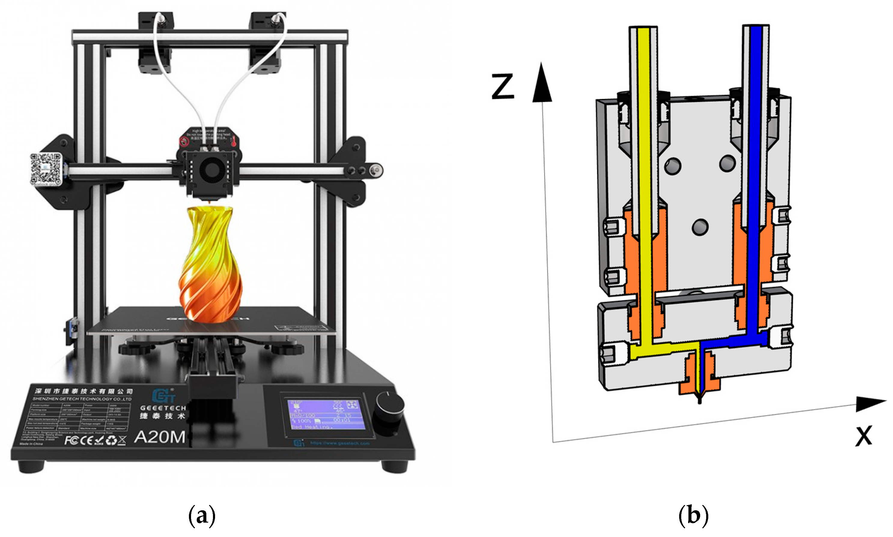
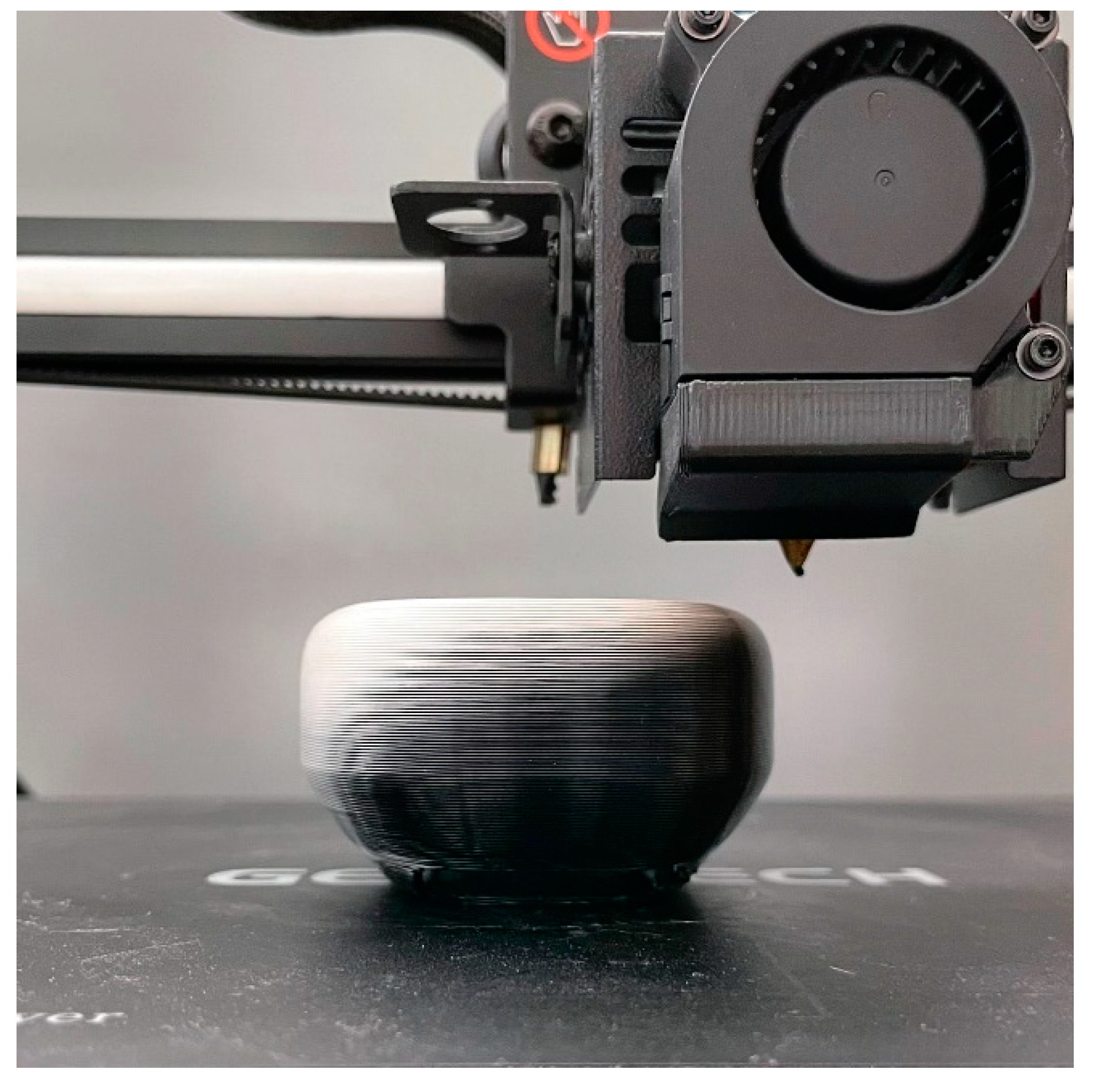
For the manufacturing of the test case, a Geeetech A20M Dual Extruder was used (Figure 8a) [39], equipped with a Marlin firmware [40] and a Cyclops hot-end [41] with a steel nozzle with a diameter of 0.8 mm. The materials reach the hot-end through two Bowden tubes, and the combined materials simultaneously flow through the same nozzle without mixing, as shown in Figure 8b.
Finally, Figure 9 shows the headphones that were produced following the workflow described above. It is possible to observe that a graduation in color appears along the z axis. Moreover, at the same z-level, due to the hot-end movement and the absence of mixing, a graduation in color appears at the same MF, confirming other results that deal with coextrusion in the literature [9].
The graded composition allows us to meet the graded properties and consequently, multiple functions can be reached in a single part, thus enabling parts consolidation and reducing assembly costs. The proposed method can be easily integrated between the design and the manufacturing workflows recently proposed for FGM/FGAM [1,14,21,29,43], overcoming the limits of the current CAM and post-processing software. For instance, Geeetech provides the color mixer software [44] that allows for linear variations of MFs along the z-axis. As in our approach, color mixer is based on the G-code editing and it enables the achievement of identical results in linear gradients along the z-axis. Unlike the color mixer and other software tools, the proposed method allows us to calculate the material fraction directly from a volumetric model, permitting a gradual transition in all the directions not only in the linear gradient along the z-axis. However, it should be considered that there are a lot of technical improvements that can be achieved to increase the quality of the products. One of these is the delay between the deposited material and the extruder control. This can be mitigated by anticipating the extrusion amount and material fraction of a quantity equal to the volume of the melting chamber between the mixing zone and the nozzle exit. Other aspects are related to the rheological properties according to the temperature, such as surface tension, viscosity, and the hot-end dynamics [45], to the deposition pattern that influences the distribution of the coextruded materials [9,45] and to the adhesion among materials.
Recent studies show the effect of the process parameters on the adhesion mechanisms between PLA and TPU, which influences the mechanical properties and is the basis of the material coextrusion [33,35,45,46,47,48]. In addition to the temperature, the main adhesion mechanisms are related to Van der Waals forces, chemical bonds, wettability, diffusion, and impurities at the boundary [48,49,50,51]. Additionally, coefficients of thermal expansion play a key role in shape and dimensional accuracy, residual stress, and interface strength. Moreover, surface roughness and shape of the interface influence adhesion, due to microscopic and macroscopic interlocking. Based on the mechanical tests and on the adhesion mechanisms models, other materials were studied in the literature such as ABS–TPU, PCL–TPU, PLA/NinjaFlex®, ABS/NinjaFlex®, CPE/PLA, and CPE/TPU [48,49,50,51], which opens new perspectives in FGAM applications.

4. Conclusions

This paper presented a methodology for the G-code computation of functionally graded material components. A workflow has been presented that allows an easy association of material distribution and surface model to the manufacturing process.
In the proposed approach, the object is geometrically modeled by standard approaches, and obtains a surface model that is exported in a standard STL file format. The process parameters, such as the layer thickness, speed, temperature, slicing strategies, and infill density, are set, and the G-code is computed as in a standard FDM workflow. At the same time, the material distribution of the FGM part is assigned to a voxel-based volumetric model and is exported as a colored point cloud. The information is then transferred from the point cloud to the G-code by matrix manipulation using a Python script. A KNN algorithm is employed to reduce the computational effort.
The process of associating material mixing through the modification of a G-code originally designed for a homogeneous component greatly reduces the time and computational power required for its generation.

Author Contributions

Conceptualization, F.L. and G.S.; methodology, G.S., F.L. and P.D.F.; validation, F.L., P.D.F. and G.S.; formal analysis, G.S., F.L., P.D.F., L.G. and S.R.; investigation, F.L., P.D.F., L.G., S.R. and G.S.; resources, G.S., R.M. and G.C.; writing—original draft preparation, F.L., G.S., P.D.F., L.G. and S.R.; writing—review and editing, G.S., R.M. and G.C.; visualization, G.S., F.L., L.G., P.D.F. and S.R.; supervision, G.S., R.M. and G.C.; project administration, G.S.; funding acquisition, G.S. All authors have read and agreed to the published version of the manuscript.

Funding

This research was partially funded by the Regional Operational Program F.S.E. 2014–2020 Veneto Region and the European Regional Development Fund POR 2014–2020, grant number “2105-0036-1463-2019”, and by the Department of Civil, Environmental, and Architectural Engineering, University of Padova, grant number “BIRD 190850”.

Institutional Review Board Statement

Not applicable.

Informed Consent Statement

Not applicable.

Data Availability Statement

The data presented in this study are available on request from the corresponding author.

Acknowledgments

The authors are grateful to Riccardo Sponchiado for the support and suggestions in manufacturing the components.

Conflicts of Interest

The authors declare no conflict of interest. The funders had no role in the design of the study; in the collection, analyses, or interpretation of data; in the writing of the manuscript; or in the decision to publish the results.

References

  1. Loh, G.H.; Pei, E.; Harrison, D.; Monzón, M.D. An Overview of Functionally Graded Additive Manufacturing. Addit. Manuf. 2018, 23, 34–44. [Google Scholar] [CrossRef] [Green Version]
  2. Sponchiado, R.; Grigolato, L.; Filippi, S.; Concheri, G.; Meneghello, R.; Savio, G. Heterogeneous Materials Additive Manufacturing: An Overview. In Design Tools and Methods in Industrial Engineering II. ADM 2021. Lecture Notes in Mechanical Engineering; Rizzi, C., Campana, F., Bici, M., Gherardini, F., Ingrassia, T., Cicconi, P., Eds.; Springer: Cham, Switzerland, 2022; pp. 462–473. ISBN 9783030912345. [Google Scholar] [CrossRef]
  3. Mahamood, R.M.; Akinlabi, E.T. Introduction to Functionally Graded Materials. In Topics in Mining, Metallurgy and Materials Engineering; Springer: Cham, Switzerland, 2017; pp. 1–8. ISBN 9783319537566. [Google Scholar] [CrossRef]
  4. Besisa, D.H.A.; Ewais, E.M.M. Advances in Functionally Graded Ceramics–Processing, Sintering Properties and Applications. Adv. Funct. Graded Mater. Struct. 2016, 1, 32. [Google Scholar]
  5. Koizumi, M. FGM Activities in Japan. Compos. Part B Eng. 1997, 28, 1–4. [Google Scholar] [CrossRef]
  6. Müller, E.; Drašar, Č.; Schilz, J.; Kaysser, W. Functionally Graded Materials for Sensor and Energy Applications. Mater. Sci. Eng. A 2003, 362, 17–39. [Google Scholar] [CrossRef]
  7. Boggarapu, V.; Gujjala, R.; Ojha, S.; Acharya, S.; Venkateswara babu, P.; Chowdary, S.; kumar Gara, D. State of the Art in Functionally Graded Materials. Compos. Struct. 2021, 262, 113596. [Google Scholar] [CrossRef]
  8. ASTM_F42; ISO/TC_261 ISO/ASTM TR 52912: 2020 Additive Manufacturing—Design—Functionally Graded Additive Manufacturing. ISO: Geneva, Switzerland, 2020.
  9. Garland, A.; Fadel, G. Design and Manufacturing Functionally Gradient Material Objects with an off the Shelf Three-Dimensional Printer: Challenges and Solutions. J. Mech. Des. 2015, 137, 111407. [Google Scholar] [CrossRef]
  10. Khondoker, M.A.H.; Asad, A.; Sameoto, D. Printing with Mechanically Interlocked Extrudates Using a Custom Bi-Extruder for Fused Deposition Modelling. Rapid Prototyp. J. 2018, 24, 921–934. [Google Scholar] [CrossRef]
  11. Kennedy, Z.C.; Christ, J.F. Printing Polymer Blends through in Situ Active Mixing during Fused Filament Fabrication. Addit. Manuf. 2020, 36, 101233. [Google Scholar] [CrossRef]
  12. Brauer, C.; Aukes, D. Applying Graded Material Transitions with Low-Cost Additive Manufacturing. Rapid Prototyp. J. 2022; ahead-of-print. [Google Scholar]
  13. Lalegani Dezaki, M.; Mohd Ariffin, M.K.A.; Hatami, S. An Overview of Fused Deposition Modelling (FDM): Research, Development and Process Optimisation. Rapid Prototyp. J. 2021, 27, 562–582. [Google Scholar] [CrossRef]
  14. Muller, P.; Mognol, P.; Hascoet, J.Y. Functionally Graded Material (FGM) Parts: From Design to the Manufacturing Simulation. In Proceedings of the ASME 2012 11th Biennial Conference on Engineering Systems Design and Analysis, Nantes, France, 2–4 July 2012; pp. 123–131. [Google Scholar] [CrossRef]
  15. Savio, G.; Meneghello, R.; Rosso, S.; Concheri, G. 3D Model Representation and Data Exchange for Additive Manufacturing. In Lecture Notes in Mechanical Engineering; Springer: Cham, Switzerland, 2019; Volume 3, pp. 412–421. ISBN 9783030123468. [Google Scholar] [CrossRef]
  16. Grigolato, L.; Rosso, S.; Meneghello, R.; Concheri, G.; Savio, G. Heterogeneous Objects Representation for Additive Manufacturing: A Review. Instant J. Mech. Eng. 2019, 1, 14–23. [Google Scholar] [CrossRef]
  17. Wang, D.; Liu, L.; Deng, G.; Deng, C.; Bai, Y.; Yang, Y.; Wu, W.; Chen, J.; Liu, Y.; Wang, Y.; et al. Recent Progress on Additive Manufacturing of Multi-Material Structures with Laser Powder Bed Fusion. Virtual Phys. Prototyp. 2022, 17, 329–365. [Google Scholar] [CrossRef]
  18. Richards, D.; Amos, M. Design with Gradients: Bio-Inspired Computation for Digital Fabrication. Acadia 2014, 101–110. [Google Scholar] [CrossRef]
  19. Steuben, J.C.; Iliopoulos, A.P.; Michopoulos, J.G. Implicit Slicing for Functionally Tailored Additive Manufacturing. Comput. Des. 2016, 77, 107–119. [Google Scholar]
  20. Aremu, A.K.; Adetifa, B.O. Investigating the Suitability of Different Heat Storage Media in Double Exposure Box Type Solar Cookers. J. Appl. Sci. Eng. Technol. 2016, 16, 1–9. [Google Scholar]
  21. Yao, X.; Moon, S.K.; Bi, G.; Wei, J. A Multi-Material Part Design Framework in Additive Manufacturing. Int. J. Adv. Manuf. Technol. 2018, 99, 2111–2119. [Google Scholar] [CrossRef]
  22. Garcia, D.; Wu, Z.; Kim, J.Y.; Yu, H.Z.; Zhu, Y. Heterogeneous Materials Design in Additive Manufacturing: Model Calibration and Uncertainty-Guided Model Selection. Addit. Manuf. 2019, 27, 61–71. [Google Scholar] [CrossRef]
  23. Hällgren, S.; Pejryd, L.; Ekengren, J. 3D Data Export for Additive Manufacturing—Improving Geometric Accuracy. Procedia CIRP 2016, 50, 518–523. [Google Scholar] [CrossRef] [Green Version]
  24. Bader, C.; Kolb, D.; Weaver, J.C.; Sharma, S.; Hosny, A.; Costa, J.; Oxman, N. Making Data Matter: Voxel Printing for the Digital Fabrication of Data across Scales and Domains. Sci. Adv. 2018, 4, eaas8652. [Google Scholar] [CrossRef] [Green Version]
  25. Skylar-Scott, M.A.; Mueller, J.; Visser, C.W.; Lewis, J.A. Voxelated Soft Matter via Multimaterial Multinozzle 3D Printing. Nature 2019, 575, 330–335. [Google Scholar] [CrossRef]
  26. Bader, C.; Kolb, D.; Weaver, J.C.; Oxman, N. Data-Driven Material Modeling with Functional Advection for 3D Printing of Materially Heterogeneous Objects. 3D Print. Addit. Manuf. 2016, 3, 71–78. [Google Scholar] [CrossRef]
  27. Kaufman, A.; Cohen, D.; Yagel, R. Volume Graphics. Computer 1993, 26, 51–64. [Google Scholar] [CrossRef]
  28. Bacciaglia, A.; Ceruti, A.; Liverani, A. A Systematic Review of Voxelization Method in Additive Manufacturing. Mech. Ind. 2019, 20, 630. [Google Scholar] [CrossRef] [Green Version]
  29. Grigolato, L.; Rosso, S.; Meneghello, R.; Concheri, G.; Savio, G. Design and Manufacturing of Graded Density Components by Material Extrusion Technologies. Addit. Manuf. 2022, 57, 102950. [Google Scholar] [CrossRef]
  30. M163—Set Mix Factor. Available online: https://marlinfw.org/docs/gcode/M163.html (accessed on 11 October 2022).
  31. Select Tool. Available online: https://marlinfw.org/docs/gcode/T001-T002.html (accessed on 11 October 2022).
  32. Data Sheets & 3D Printing Guides. Available online: https://fillamentum.com/pages/data-sheets-and-3d-printing-guides/ (accessed on 11 October 2022).
  33. Brancewicz-Steinmetz, E.; Sawicki, J.; Byczkowska, P. The Influence of 3D Printing Parameters on Adhesion between Polylactic Acid (PLA) and Thermoplastic Polyurethane (TPU). Materials 2021, 14, 6464. [Google Scholar] [CrossRef]
  34. Rahmatabadi, D.; Ghasemi, I.; Baniassadi, M.; Abrinia, K.; Baghani, M. 3D Printing of PLA-TPU with Different Component Ratios: Fracture Toughness, Mechanical Properties, and Morphology. J. Mater. Res. Technol. 2022, 21, 3970–3981. [Google Scholar] [CrossRef]
  35. Żur, A.; Żur, P.; Michalski, P.; Baier, A. Preliminary Study on Mechanical Aspects of 3D-Printed PLA-TPU Composites. Materials 2022, 15, 2364. [Google Scholar] [CrossRef]
  36. Ranellucci, A. Slic3r. Available online: https://slic3r.org/ (accessed on 21 January 2023).
  37. Michalatos, P.; Payne, A. Monolith: The Biomedical Paradigm and the Inner Complexity of Hierarchical Material Design. In Proceedings of the Complexity & Simplicity—Proceedings of the 34th eCAADe Conference, Oulu, Finland, 22–26 August 2015; Volume 1, pp. 445–454. [Google Scholar]
  38. Savio, G.; Meneghello, R.; Concheri, G. Design of Variable Thickness Triply Periodic Surfaces for Additive Manufacturing. Prog. Addit. Manuf. 2019, 4, 281–290. [Google Scholar] [CrossRef]
  39. Geeetech A20M User Manual. Available online: https://www.geeetech.com/download.html?version_id=426 (accessed on 9 December 2022).
  40. Marlin Firmware. Available online: https://marlinfw.org/ (accessed on 11 October 2022).
  41. Cyclops Drawings. Available online: https://e3d-online.zendesk.com/hc/en-us/articles/360017132577-Cyclops-Drawings (accessed on 11 October 2022).
  42. E3D Cyclops. Available online: https://grabcad.com/library/e3d-cyclops-1 (accessed on 11 October 2022).
  43. Rosso, S.; Uriati, F.; Grigolato, L.; Meneghello, R.; Concheri, G.; Savio, G. An Optimization Workflow in Design for Additive Manufacturing. Appl. Sci. 2021, 11, 2572. [Google Scholar] [CrossRef]
  44. Shenzhen Getech Technology Co., Ltd. Guide of Color Mixer Software. Available online: https://www.geeetech.com/download.html?version_id=85 (accessed on 11 January 2023).
  45. Sponchiado, R.; Rosso, S.; Fabbro, P.D.; Grigolato, L.; Elsayed, H.; Maltauro, M.; Uccheddu, F.; Meneghello, R.; Concheri, G.; Savio, G. Modeling Materials Coextrusion in Polymers Additive Manufacturing. Materials 2023, 16, 820. [Google Scholar] [CrossRef]
  46. Xu, T.; Shen, W.; Lin, X.; Xie, Y.M. Additively Manufactured Thermoplastic Polyurethane (TPU) Mold for Concrete Casting of Complex Structure. Rapid Prototyp. J. 2022, 28, 1717–1730. [Google Scholar] [CrossRef]
  47. Arifvianto, B.; Satiti, B.E.; Salim, U.A.; Suyitno; Nuryanti, A.; Mahardika, M. Mechanical Properties of the FFF Sandwich-Structured Parts Made of PLA/TPU Multi-Material. Prog. Addit. Manuf. 2022, 7, 1213–1223. [Google Scholar] [CrossRef]
  48. Tamburrino, F.; Graziosi, S.; Bordegoni, M. The Influence of Slicing Parameters on the Multi-Material Adhesion Mechanisms of FDM Printed Parts: An Exploratory Study. Virtual Phys. Prototyp. 2019, 14, 316–332. [Google Scholar] [CrossRef]
  49. Rahmatabadi, D.; Aberoumand, M.; Soltanmohammadi, K.; Soleyman, E.; Ghasemi, I.; Baniassadi, M.; Abrinia, K.; Zolfagharian, A.; Bodaghi, M.; Baghani, M. A New Strategy for Achieving Shape Memory Effects in 4D Printed Two-Layer Composite Structures. Polymers 2022, 14, 5446. [Google Scholar] [CrossRef] [PubMed]
  50. Freund, R.; Watschke, H.; Heubach, J.; Vietor, T. Determination of Influencing Factors on Interface Strength of Additively Manufactured Multi-Material Parts by Material Extrusion. Appl. Sci. 2019, 9, 1782. [Google Scholar] [CrossRef] [Green Version]
  51. Yin, J.; Lu, C.; Fu, J.; Huang, Y.; Zheng, Y. Interfacial Bonding during Multi-Material Fused Deposition Modeling (FDM) Process Due to Inter-Molecular Diffusion. Mater. Des. 2018, 150, 104–112. [Google Scholar] [CrossRef]
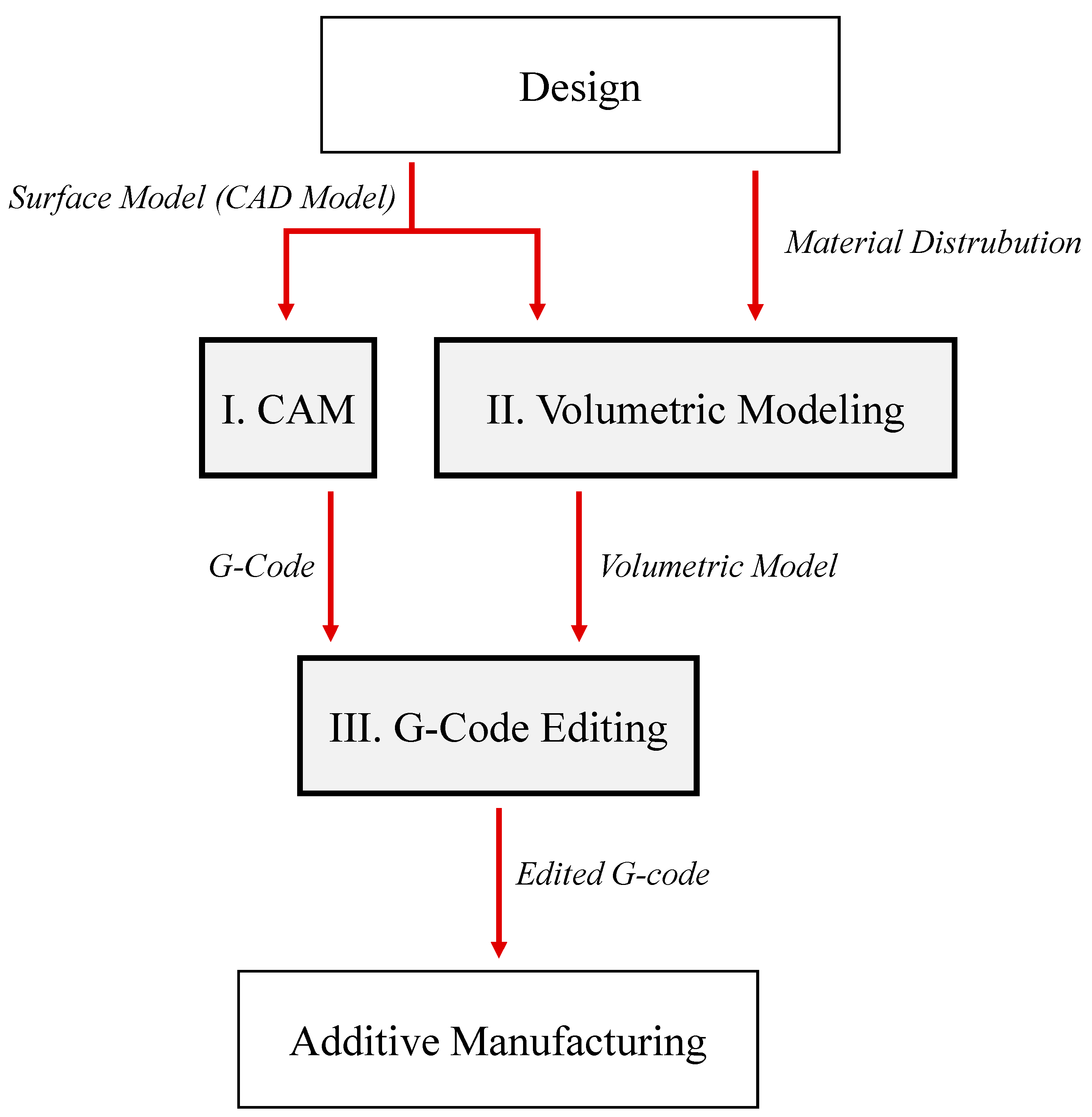
Figure 1. Overview of the proposed method.
Applsci 13 01467 g001
Figure 2. Headphone used as inspiration for the test case and parts identification.
Applsci 13 01467 g002
Figure 3. Surface model: main dimensions and internal detail.
Applsci 13 01467 g003
Figure 4. The red curve represents the MF according to z coordinate. On the right, there is the visualization of the model, in which the black color represents the PLA and the white represents TPU. The highest gradient in MFs stands on the ear pad.
Applsci 13 01467 g004
Figure 5. Grasshopper definition for the volumetric modeling.
Applsci 13 01467 g005
Figure 6. Point cloud of the volumetric information with different colors according to the material fraction.
Applsci 13 01467 g006
Figure 7. (a) Overlapping of the two-point clouds, i.e., the point cloud of the volumetric information and the point cloud of the path of the tool (the small points). (b) Point cloud of the path of the tool with the additional information regarding the material properties visualized with a grade of colors. (c) Color map.
Applsci 13 01467 g007
Figure 8. (a) The Geeetech A20M Dual Extruder. (b) CAD model adapted from GrabCAD [42] of the Cyclops hot-end representation.
Applsci 13 01467 g008
Figure 9. Manufactured part using functionally graded material.
Applsci 13 01467 g009
Table 1. Main properties of the chosen materials [32].
PropertiesPLA ExtrafillFlexfill TPU 98A
Density [g/cm3]1.241.23
Ultimate tensile strength [MPa]6053.7
Elongation at break (%)6318
Elastic modulus [MPa]3600160 *
Print temperature range [°C]190–210220–240
Bed temperature range [°C]55–6050–60
* Measured by mechanical tests.
Table 2. Process parameters.
Nozzle temperature220 °CLine width and nozzle diameter0.8 mm
Bed temperature60 °CNumber of perimeters2
InfillCubic, 30%Retraction enabledFalse
Infill/perimeters overlap15%Supports enabledTrue
Initial/top/bottom print speed15 mm/sSupport angle70°
Travel speed80 mm/sFlow100%
Print speed30 mm/sTop/bottom thickness1.6 mm
Layer height0.4 mmFan speed100%
Disclaimer/Publisher’s Note: The statements, opinions and data contained in all publications are solely those of the individual author(s) and contributor(s) and not of MDPI and/or the editor(s). MDPI and/or the editor(s) disclaim responsibility for any injury to people or property resulting from any ideas, methods, instructions or products referred to in the content.