Article

Adaptability Evaluation of Rotary Jet Grouting Pile Composite Foundation for Shallow Buried Collapsible Loess Tunnel

1
School of Civil Engineering, Weifang University, Weifang 261061, China
2
School of Highway, Chang’an University, Xi’an 710064, China
3
State Key Laboratory for Geomechanics and Deep Underground Engineering, China University of Mining and Technology, Xuzhou 221116, China
*
Author to whom correspondence should be addressed.
Appl. Sci. 2023, 13(3), 1570; https://doi.org/10.3390/app13031570
Submission received: 18 December 2022 / Revised: 4 January 2023 / Accepted: 5 January 2023 / Published: 26 January 2023
(This article belongs to the Special Issue Future Trends in Tunnel and Underground Engineering)

Abstract

:
The deformation control effect of loess tunnel composite foundation plays an important role in optimization design and reinforcement effect evaluation. Systematically evaluate the adaptability of the composite foundation of jet grouting pile in shallow collapsible loess tunnel. Taking the shallow buried section of Fujiyao Tunnel with a buried depth of 20 m as an example, using MIDAS finite element numerical simulation software, the foundation deformation control during construction and settlement control after construction are systematically studied, the differential deformation control is analyzed, and the reinforcement effect of the tunnel bottom is evaluated. The results show that the uplift displacement can be controlled by changing the pile length and increasing the replacement ratio. The combination of long and short piles can significantly reduce the uneven settlement and plastic zone of the foundation. The uneven settlement of 9 mm can be used as the evaluation index of the composite foundation reinforcement effect in a shallow buried section of the loess tunnel.

1. Introduction

The stress and deformation distribution of the loess tunnel foundation is uneven. The area with small stress is concentrated in the middle of the inverted arch, while the stress distribution area of the wall foot is large, and other locations are between the two [1,2]. Due to the low strength and large deformation of the tunnel base, improper treatment may lead to excessive deformation of the tunnel structure and uneven settlement. Especially when the external water environment changes, it is easy to cause changes in the moisture content of the tunnel base, causing instability of the arch foot and wall foot, or even collapse. The problem of tunnel base reinforcement in collapsible loess bases needs to be solved urgently [3,4]. Table 1 shows the statistics of tunnel bottom diseases of some operating loess tunnels in China in recent years.
At present, academia has carried out a lot of research on tunnel base reinforcement, and the foundation reinforcement measures are diverse [6,7]. To improve the bearing capacity of the highway tunnel foundation, according to the characteristics of the surrounding rock of a highway tunnel, Yang et al. (2009) adopt horizontal pile jet grouting for pre- support at the portal section [8]. Huang et al. (2022) simulated four tunnel reinforcement schemes (the right tunnel annular reinforcement, the left tunnel annular reinforcement, the double tunnel annular reinforcement, and the cement wall reinforcement between left and right tunnels). Through a series of three-dimensional numerical analysis, the interaction mechanism of double tunnels in the construction process was revealed, including surface settlement, tunnel deformation, convergence deformation of tunnel lining, and internal force of tunnel lining [9]. Qiu et al. (2018) applied a three-dimensional finite element model to the Fujiayao tunnel in the loess stratum to deeply understand the consolidation settlement after jetted grouting pile reinforcement of tunnel foundation [5]. In order to study the influence of base reinforcement on the tunnel, Sun et al. (2019) conducted a finite element analysis based on the previously reported centrifuge model test without base reinforcement and analyzed the influence of Young’s modulus and depth of reinforced soil on the tunnel deformation [10]. In many reinforcement measures, pile foundation, as one of the commonly used forms of base reinforcement, has been widely studied by scholars. Among them, pile length, pile diameter, and pile stiffness are the key factors to be considered when strengthening the loess tunnel base. Huang et al. (2020) takes a subway tunnel as an example and use finite element software to simulate the influence of four reinforcement methods on foundation settlement, namely, deep hole grouting reinforcement, deep hole grouting combined with radial grouting reinforcement, bolt reinforcement, and tension bolt deep hole grouting reinforcement under different gap conditions [11]. Zhao et al. (2010) used Plaxis 3D tunnel finite element software to study the distribution law of pile foundation lateral deformation and settlement change along the pile shaft during the whole tunnel crossing process and analyzed the influence of pile length on pile foundation deformation [12].
For loess tunnel, the base is a weak surrounding rock with low strength, and the deformation is large during construction. To explain the progressive failure of roof collapse in deep tunnels, Han (2018) studied the progressive collapse mechanism and collapse block shape of a deep circular tunnel under plane strain conditions. Based on the nonlinear power law failure criterion considering the change of dilatancy angle and separation velocity, the analytical solution of the collapse block shape curve of circular tunnels is derived. In addition, the variable dilatancy angle criterion for the progressive failure of deep tunnels is also obtained [13]. Based on a new three-dimensional limit equilibrium model, Han (2021) studied the stability of the tunnel face crossing the fault fracture zone with high water pressure. To reveal the influence of the difference in the permeability coefficients of the strata on the distribution of the seepage field near the working face, the tunnel was numerically simulated. A new limit equilibrium model consisting of a trapezoid and a prism is proposed by introducing the geological interface effect. By considering the influence of seepage force and geological interface, the distributed load exerted by the prism on the trapezoid is deduced [14]. When reinforcing the tunnel base, many construction schemes adopt the form of a composite foundation. The composite foundation reinforcement measures can reduce the uplift displacement of the tunnel bottom and the overall settlement caused by water immersion [15]. Li et al. (2018) studied the reinforcement effect of a high-pressure jet grouting pile on the foundation of deep-buried large-span collapsible loess tunnel through on-site displacement and stress monitoring of the Fujiayao loess tunnel [16]. Liu et al. (2013) analyzed the mechanism of high-pressure chemical mixing pile strengthening loess tunnel base, gave the strength calculation formula of the composite foundation of high-pressure chemical mixing pile strengthening loess tunnel foundation, and established a finite element model for settlement calculation [17]. Wu et al. (2019) carried out a numerical simulation of pile group foundation engineering of a shield tunnel in which the Nanjing Metro Airport Line traversed the Beijing-Shanghai high-speed railway and analyzed the characteristics of horizontal displacement of pile foundation along the bridge deck in the whole traversing process. On this basis, taking the horizontal displacement of a single pile as the evaluation index, the reinforcement effects of grouting reinforcement, longitudinal beam reinforcement and cross support reinforcement, and bored pile reinforcement are compared and analyzed [18]. Li et al. (2020) take the pile group foundation of the shield tunnel of Shenzhen Metro Line 10 passing through the Guangzhou Shenzhen Expressway Bridge as an example, analyzes the influence of shield tunnel construction on the pile stability by using numerical simulation, and discuss the stress transfer mechanism of the pile foundation during the support and tunneling stages of the shield tunnel [19]. According to the research, the composite foundation reinforcement at the bottom of the tunnel not only improves the bearing capacity of the foundation but also reduces the structural deformation and post-construction settlement.
Deformation control of tunnel composite foundations mainly includes basement uplift deformation and post-construction settlement during construction [20]. Therefore, the deformation control effect of composite foundations needs more attention in the optimization design and reinforcement effect evaluation. In recent years, with the widespread application of composite foundations, the jet grouting pile composite foundation has become a new reinforcement measure and is widely used. The jet grouting pile composite foundation can better reduce the loess collapsibility, showing a good reinforcement effect. Based on the shallow buried section of Fujiayao tunnel with a depth of 20 m, this paper studies the control of basement deformation, post-construction settlement, and differential deformation in the construction process by using the numerical simulation method for reference to the calculation concept of foundation settlement, and systematically evaluates the reinforcement effect of rotary jet pile composite foundation.

2. Model Establishment

2.1. Project Status

The supporting project is the Lanzhou Fujiayao Tunnel with a total length of 802 m. The research object is a 20 m shallow buried section. Fujiayao tunnel is located in a collapsible loess area with large thicknesses and obvious collapsibility. The whole foundation of the Fujiayao tunnel is reinforced by high-pressure jet grouting piles. Figure 1 shows the geological conditions.

2.2. Model Test

2.2.1. Similarity Ratio

According to the site conditions, the test site, and the test itself, the geometric dimension ratio of the model is determined to be 1:40, and the similarity ratio of the gravity is Cγ = 1; Poisson’s ratio, strain, friction angle similarity ratio: Cμ = Cε = Cφ = 1; Similarity ratio of strength, stress, cohesion, and elastic modulus: CR = Cσ = Cc = CE = 40. The main mechanical parameters of the model are defined as follows:
(1) Surrounding rock: unit weight γ = 1.52 g/cm3, elastic modulus E = 1.3 MPa, Poisson’s ratio μ = 0.3; collapsibility coefficientδs = 0.043;
(2) Formwork concrete and shotcrete: elastic modulus E = 3300 MPa, Poisson’s ratio μ = 0.38, thickness h = 15 mm;
(3) Rotary jet grouting pile: elastic modulus E = 260 MPa, Poisson’s ratio μ = 0.22.

2.2.2. Material Selection

Table 2 shows the mechanical parameters of the model structure. The selection of the surrounding rock structure is based on the research results of the research group of Zhang Yanjie from Lanzhou Jiaotong University. Barite powder, bentonite, industrial salt, gypsum, and standard sand are mixed and stirred according to the percentage of 8:12:45:25:10. The model pile is made of cement with the mark of PO32.5 and loess with the particle size less than 1 mm and water in a certain mix proportion.
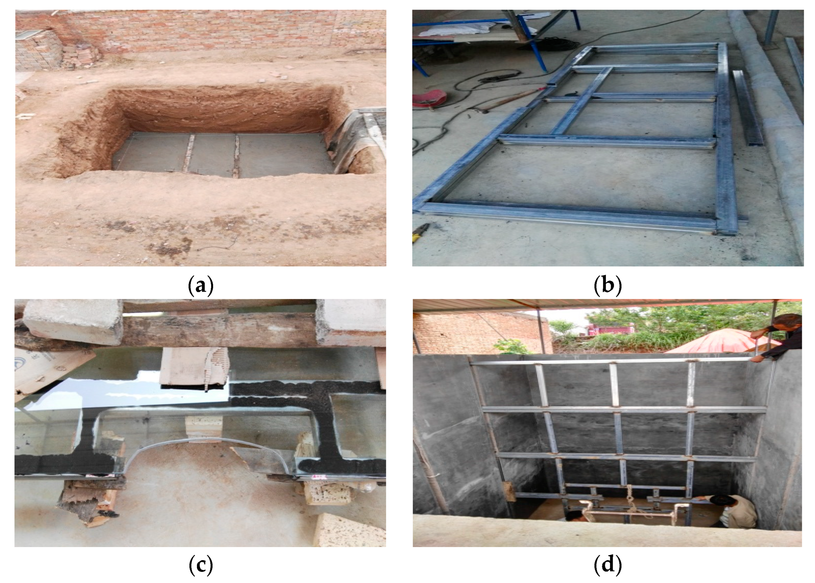
The purpose of this model test is to determine the stress and deformation behavior of the tunnel base during the tunnel construction and excavation process, and when the excavation is completed and the initial support is closed. During the test, fill the surrounding rock below the inverted arch, fill the initial support model with hard soil, place the initial support similar model, and finally, pour the entire surrounding rock to the final elevation. Based on this, the stress and deformation characteristics of the tunnel base and surrounding rock are studied, the deformation process of the tunnel lining structure is observed, and the interaction between initial support and surrounding rock is analyzed. Figure 2 and Figure 3 respectively show the fabrication of the model groove and surrounding rock.

2.3. Numerical Simulation

2.3.1. Model Establishment

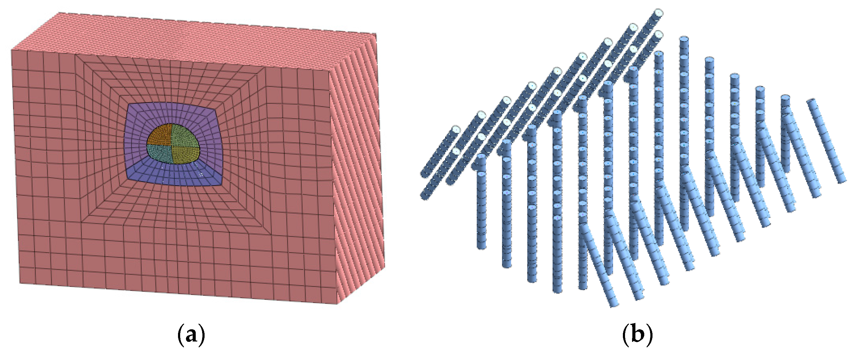
As a common research method in tunnel engineering, numerical analysis can simulate the stress and displacement field at all positions during tunnel excavation, and MIDAS GTS numerical software was used as the numerical analysis tool. Moore-coulomb yield criterion was adopted for surrounding rock filling. Shell element and solid element were selected for initial support and pile, and Goodman contact was selected for pile-soil coupling. Table 3 shows the material-related parameters.
A numerical model with the same size as the model test, consistent boundary conditions, and a consistent excavation and support scheme is established. The lining and support pile adopt the pre-support mode, the excavation footage is 5 cm, and the simulation is carried out in strict accordance with the on-site model test construction excavation scheme. The numerical model is shown in Figure 4, with a total of 703,689 units. The pile body and lining structure use solid units and plate units, respectively.

2.3.2. Pile Soil Coupling

In practical engineering, the pile is buried in the surrounding rock of the tunnel base, and there is a certain cohesiveness between the pile and the soil at the tunnel bottom. When establishing the composite foundation model in MIDAS GTS, the contact between piles and soil must be considered to simulate the actual project more truly. MIDAS GTS software contains rich interface elements and Goodman Pile elements to simulate the interaction between piles and soil. In this paper, the solid is used to simulate the pile, and the Goodman element is used to simulate the contact between the pile and the soil.

3. Analysis of Deformation Control

3.1. Analysis of Deformation Control during Construction

3.1.1. Reinforcement Opportunity

Different from the building foundation, the tunnel bottom reinforcement measures cannot be taken in advance for tunnel works, and corresponding reinforcement measures can only be taken during the tunnel excavation or before the closure of the inverted arch after the tunnel excavation is completed [21]. To reduce the displacement of the soil at the bottom of the tunnel during construction and exert the bearing capacity of the surrounding rock itself, the influence of reinforcement timing on the deformation control of the surrounding rock during construction should be considered. The reinforcement opportunity can be divided into four types according to the pile construction time (See Figure 5).
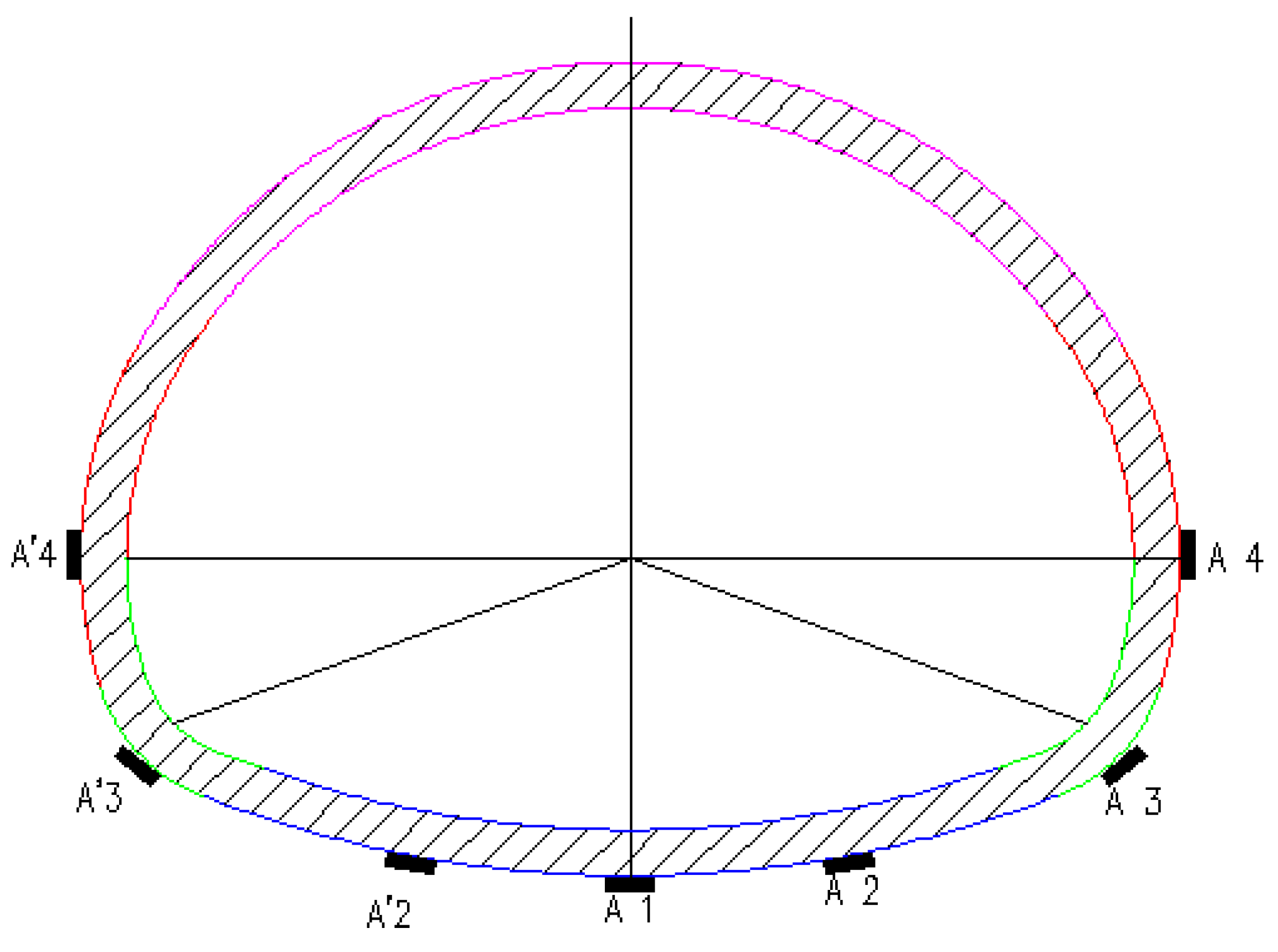
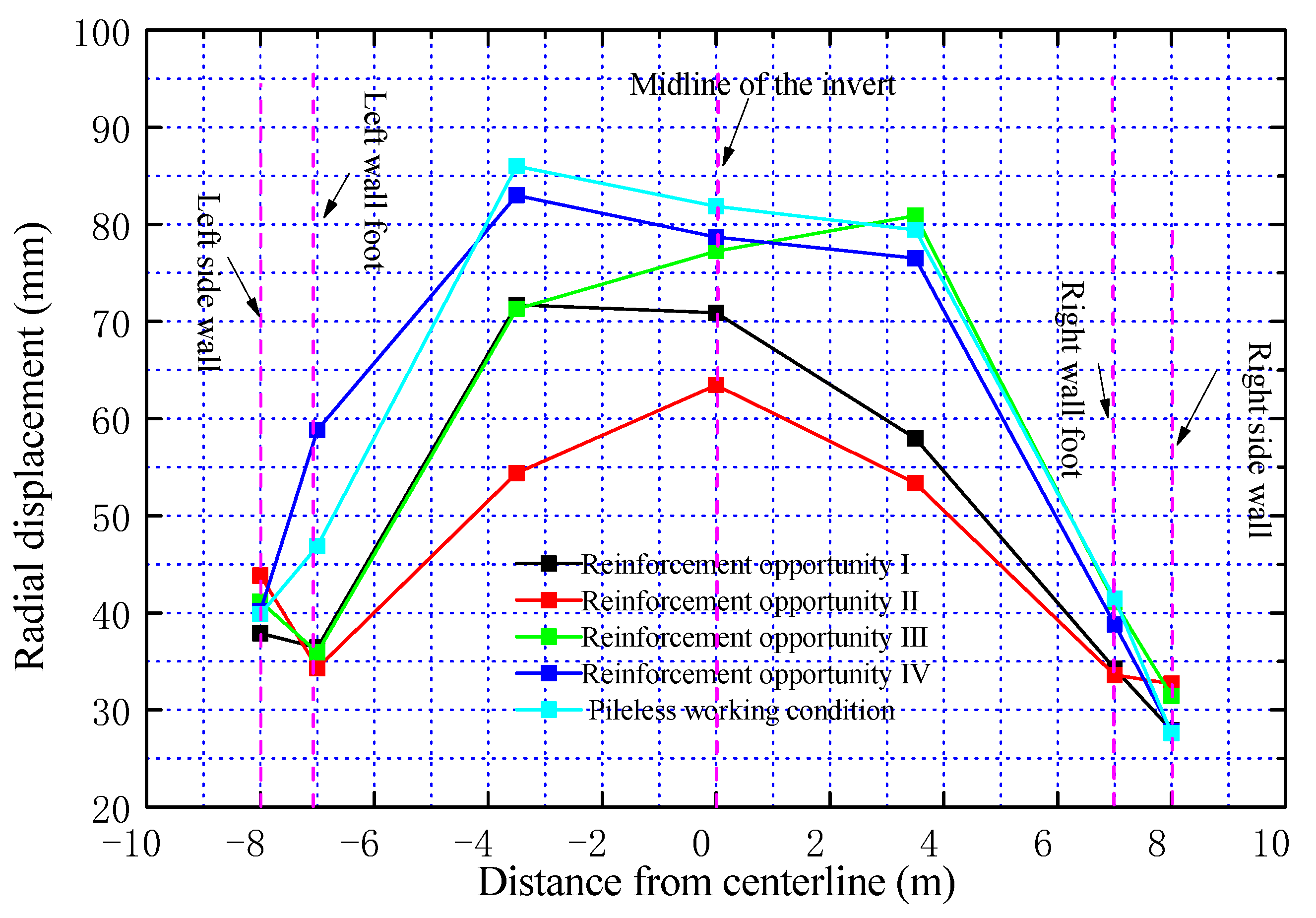
To compare and analyze the vertical displacement of the measuring point and the horizontal displacement of the side wall, Figure 6 shows the location of the measuring point, and Figure 7 shows the radial displacement of the tunnel bottom and side wall. It can be seen that the displacement control effect of the soil mass at the tunnel bottom is best when the piles are constructed two times. After the excavation of the upper bench is completed, the pile construction can also better control the displacement of the foundation soil, but the effect is poor compared with the two construction. The control effect of pile construction after excavation is basically the same as that of base soil displacement without reinforcement. Therefore, it is recommended that after the excavation of the upper right and upper left pilot tunnels in the actual project, the on-site construction personnel should timely construct the lower piles of each pilot tunnel, to achieve the best effect of base displacement control.

3.1.2. Reinforcement Scope

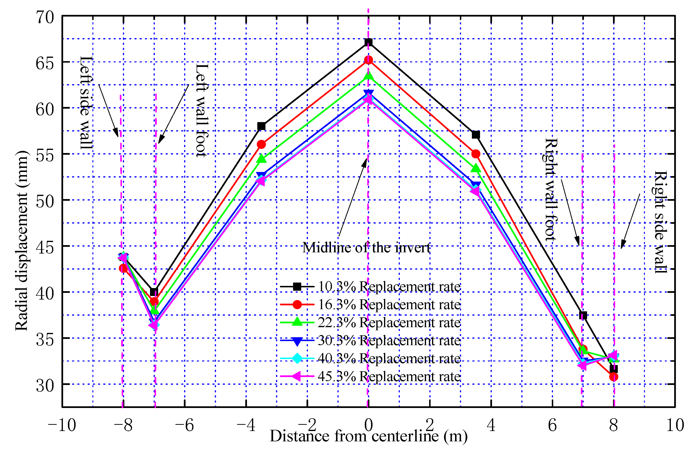
Figure 8 shows the soil displacement of the base and side wall. Refer to the research method of Peng et al. (2011) for qualitative analysis of replacement rate and pile length [22]. It can be seen that increasing the replacement rate can have a certain control effect on the base displacement. When the replacement rate is 10.3%, the uplift displacement of the basement is less than 68 mm; when the replacement rate in the original scheme is 22.3%, the displacement of the base during construction is less than 64 mm; when the replacement rate continues to increase to 40.3%, the base displacement is less than 60.43 mm, indicating that the degree of control effect is reduced. In addition, when the base displacement rate increases to a certain extent, the control effect of base displacement will be reduced. Therefore, in the actual design and construction of tunnel composite foundations, the replacement rate cannot be increased blindly, and the control of foundation deformation during the construction process should be taken as the primary goal, and the optimal replacement rate should be found. Based on the analysis of multiple factors, it is suggested that the optimal replacement rate of composite foundations in the Fujiayao shallow buried section is 30.3%.
In addition to the optimization of the horizontal reinforcement range, the optimization of the vertical reinforcement range also needs to be considered, that is, the optimization of the pile length. Figure 9 shows the soil displacement of the base and side wall under different pile lengths. It can be seen that when the control replacement rate is certain, the foundation displacement can be better controlled by increasing the pile length; when the pile length increases from 3 m to 15 m, the maximum uplift displacement of the base decreases from 73 mm to 43 mm. Compared with the increase in the replacement rate, the increase in the pile length has a better control effect on the foundation displacement. This is mainly because the increase in pile length increases the range of tunnel bottom reinforcement area to a certain extent, which reduces the thickness of soft soil in the underlying layer, thus effectively controlling the displacement of the basement uplift. The conclusion is similar to the research result of Peng et al. (2011) [22]. In addition, the deformation of the jet grouting pile itself in the reinforcement area is small, and the soil deformation is the main factor of the base uplift. Therefore, the optimal design scheme of the composite foundation of a collapsible loess tunnel can be achieved by appropriately increasing the pile length.

3.2. Analysis of Post-Construction Settlement Control

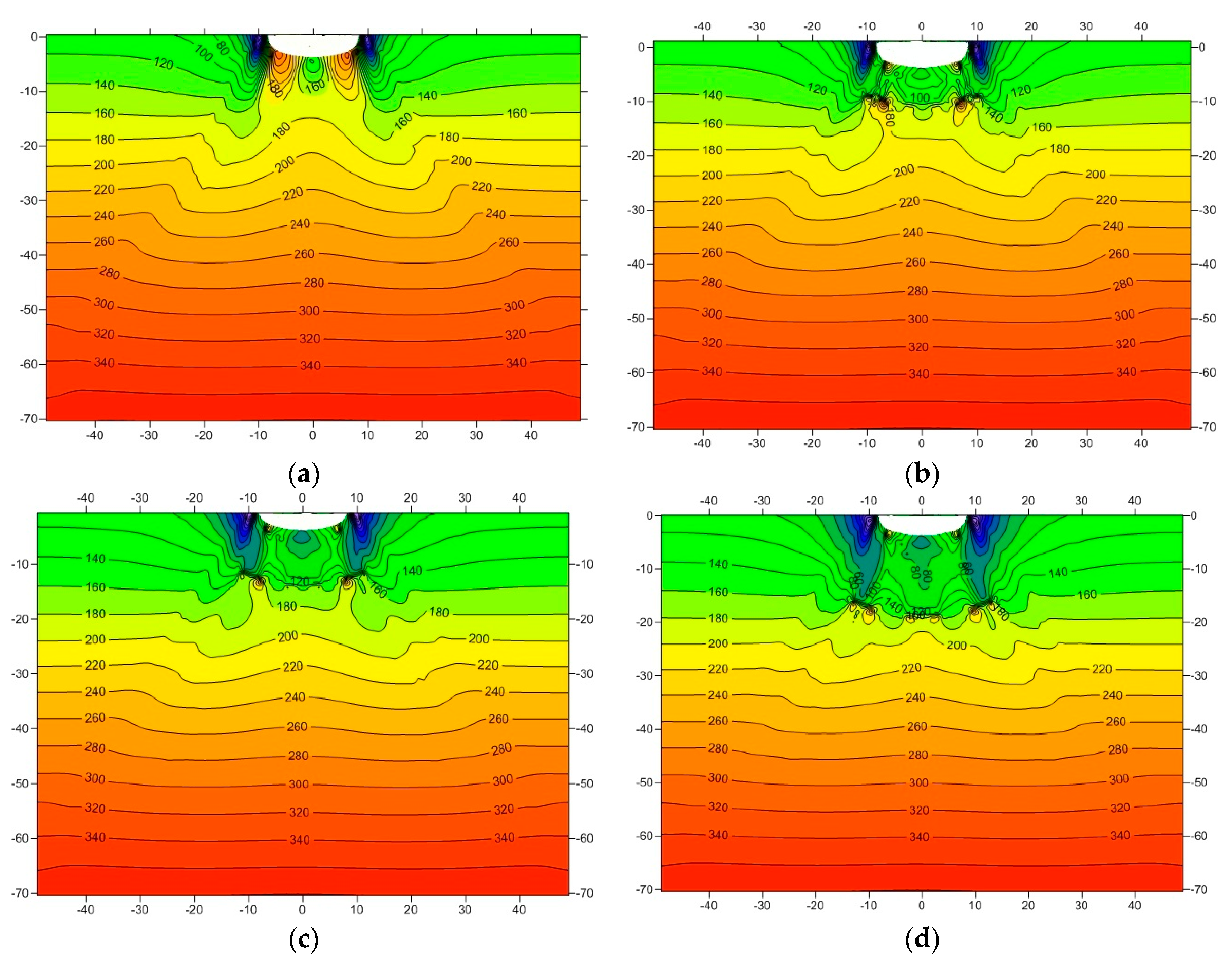
The post-construction settlement of the shallow buried section of the collapsible loess tunnel mainly includes: (1) the consolidation settlement of the soil mass at the tunnel bottom under the action of the overburden load and (2) the tunnel bottom settles under water immersion conditions. Due to the longtime consolidation settlement, this paper mainly analyzes the overall settlement under immersion. According to the model test results, the increased base stress after immersion can be taken as the additional stress of the base, as shown in Figure 8. After the foundation is immersed in water, the additional stress of the foundation soil is obviously reduced, while the additional stress of the deep soil is increased. It shows that the increase of pile length moves down the high-stress area of additional stress, and reflects the change characteristics of the tunnel bottom displacement field after immersion.
The base displacement under the conditions of different pile lengths and replacement rates is calculated using the 20 m base immersion as the baseline, as shown in Figure 9. It can be seen that the settlement of the composite foundation under immersion exceeds 10 cm. The increase in the replacement rate has little effect on controlling the foundation settlement, while the increase in the pile length can effectively control the foundation settlement. The increase in the replacement rate has little effect on controlling the foundation settlement, while the increase in the pile length can effectively control the foundation settlement, and the larger the pile length is, the better the control effect on the foundation displacement is. This is mainly because the existence of piles reduces the additional stress of soft soil in the reinforcement area, which reduces the additional stress of soil in the underlying layer, thereby reducing the tunnel bottom settlement. In addition, it also shows that the soil deformation within 5 m of the base will significantly affect the overall settlement of the lining structure. Therefore, before the composite foundation design of the loess tunnel, the immersion depth of the foundation soil should be calculated in advance.

4. Analysis of Differential Deformation Control

The differential deformation of the basement can be divided into two stages [23,24]: (1) uneven uplift displacement of the basement soil during construction and (2) uneven settlement after construction. The large differential deformation in the construction process will lead to the plastic failure of the base soil, and then the loss of part of the bearing capacity, which is contrary to the construction concept of fully exerting the self-supporting capacity of surrounding rock in NATM. Therefore, it is necessary to control the differential deformation of soil mass during construction. In addition, after the base is immersed in water, the uneven distribution of additional stress on the base will lead to the uneven distribution of the base settlement, which is extremely unfavorable to the safety of the lining structure. For tunnels with soft soil foundations, the influence of uneven settlement on structure safety must be considered in the design of foundation reinforcement.
The uneven uplift deformation of the foundation is mainly due to the different degrees of soil unloading at each part of the foundation after the tunnel construction, that is, the unloading force is unevenly distributed at the base [25]. The unloading force of the foundation is the same as the additional stress in the building composite foundation, and the uplift displacement of the foundation is caused by the uplift force. There are two methods to make the deformation of the substrate relatively uniform. One is to make the additional stress of the foundation evenly distributed, and the other is to change the resilience modulus of the composite foundation. This method is easy to realize in construction and is called the variable stiffness method.

4.1. Analysis of Differential Deformation Control during Construction

4.1.1. Variable Stiffness Method

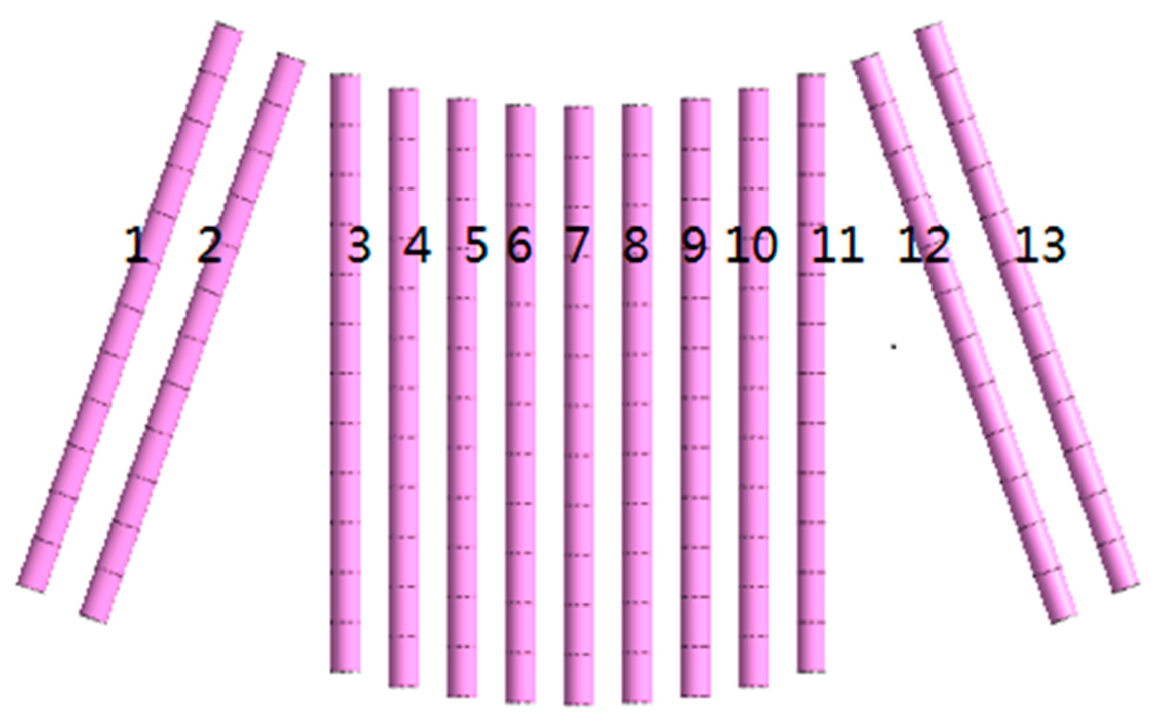
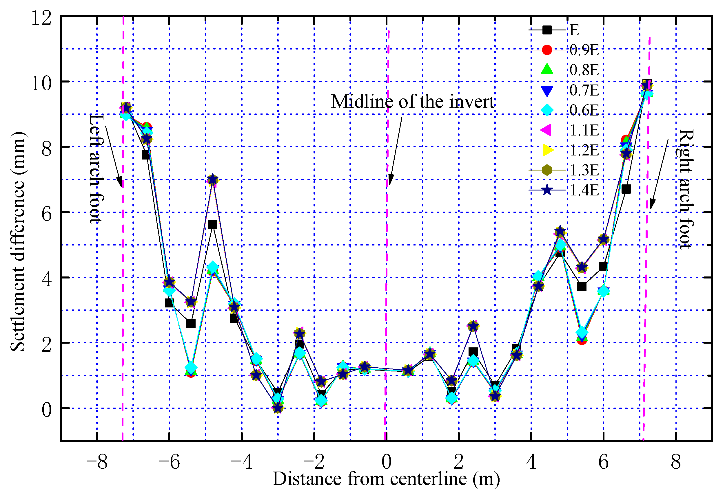
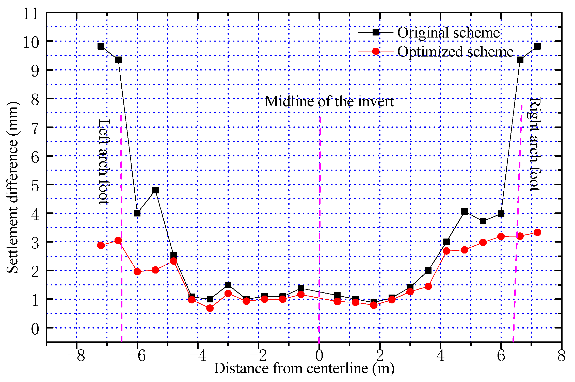
After foundation reinforcement, due to the effect of piles in the reinforcement area, the additional stress decreases the modulus of composite foundation increases, and the deformation value of each measuring point decreases. Compared with natural foundation, differential settlement is also reduced. However, the differential settlement at the foot of the wall is still very large (9.399 mm), and a plastic zone is formed at the foot of the wall. To reduce the uneven settlement of the foundation, it is necessary to increase the pile stiffness in the area with large additional stress or reduce the pile stiffness in the area with small additional stress. By increasing the displacement of the wall foot and reducing the displacement from the middle of the arch, the displacement can be reduced. For the convenience of analysis, the piles are arranged from left to right and numbered as shown in Figure 10. It can be seen from the figure that the stiffness of 1 #, 2 #, 3 #, 11 #, 12 #, and 13 # piles at the foot of the wall should be reduced, or the stiffness of other piles should be increased. The elastic modulus E of the pile foundation is reduced to 0.9 E, 0.8 E, 0.7 E, 0.6 E, and 0.5 E respectively, and the pile stiffness in the middle area is increased to 1.1 E, 1.2 E, 1.3 E, and 1.4 E to analyze the uneven settlement of each part, as shown in Figure 11. It can be seen that increasing the pile stiffness at the bottom of the wall or reducing the pile stiffness at the middle of the inverted arch has a poor control effect on uneven settlement. Therefore, it is not recommended to use the variable stiffness method to control uneven settlement during construction.

4.1.2. Long Pile and Short Pile Combination Method

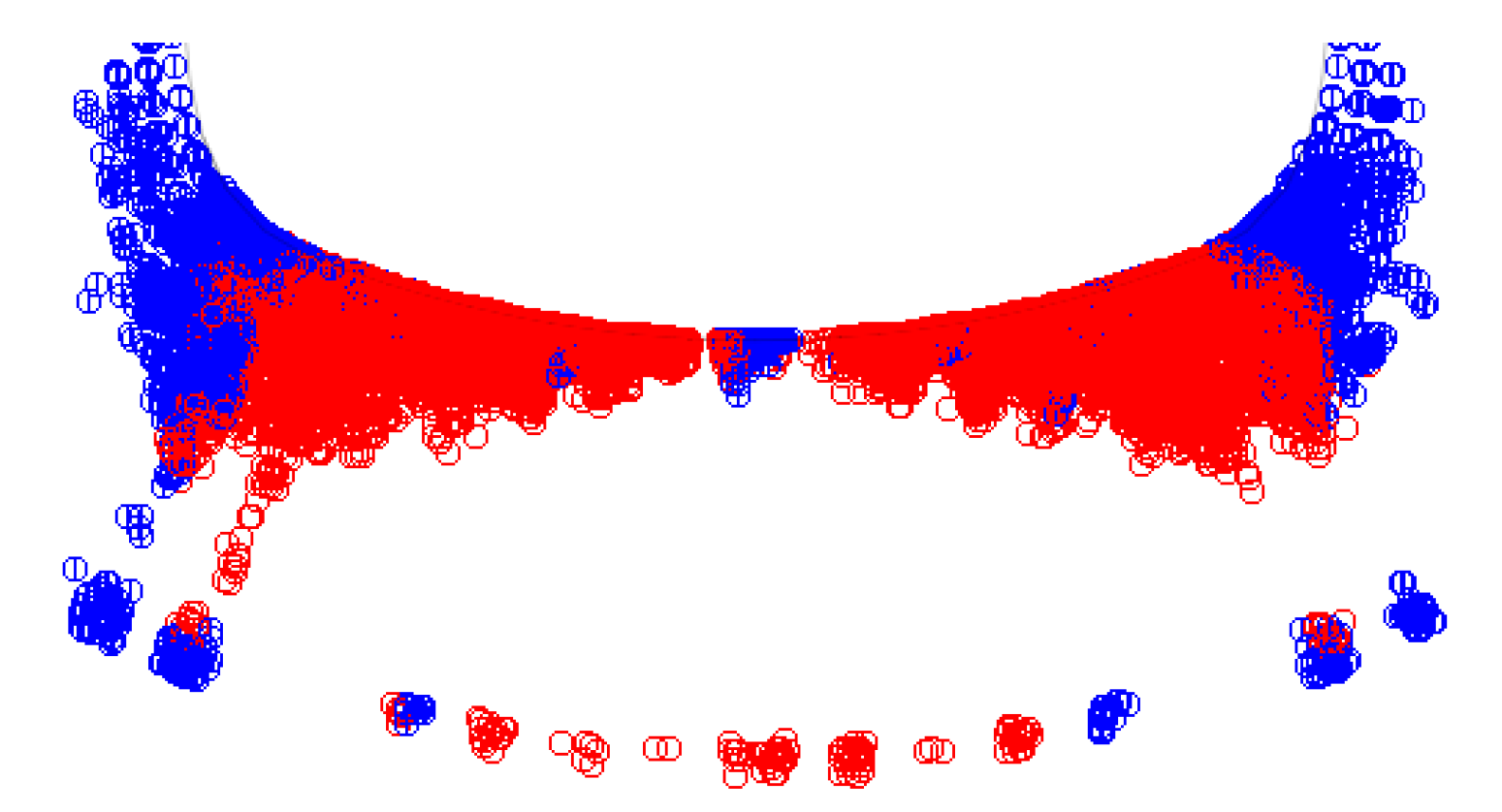
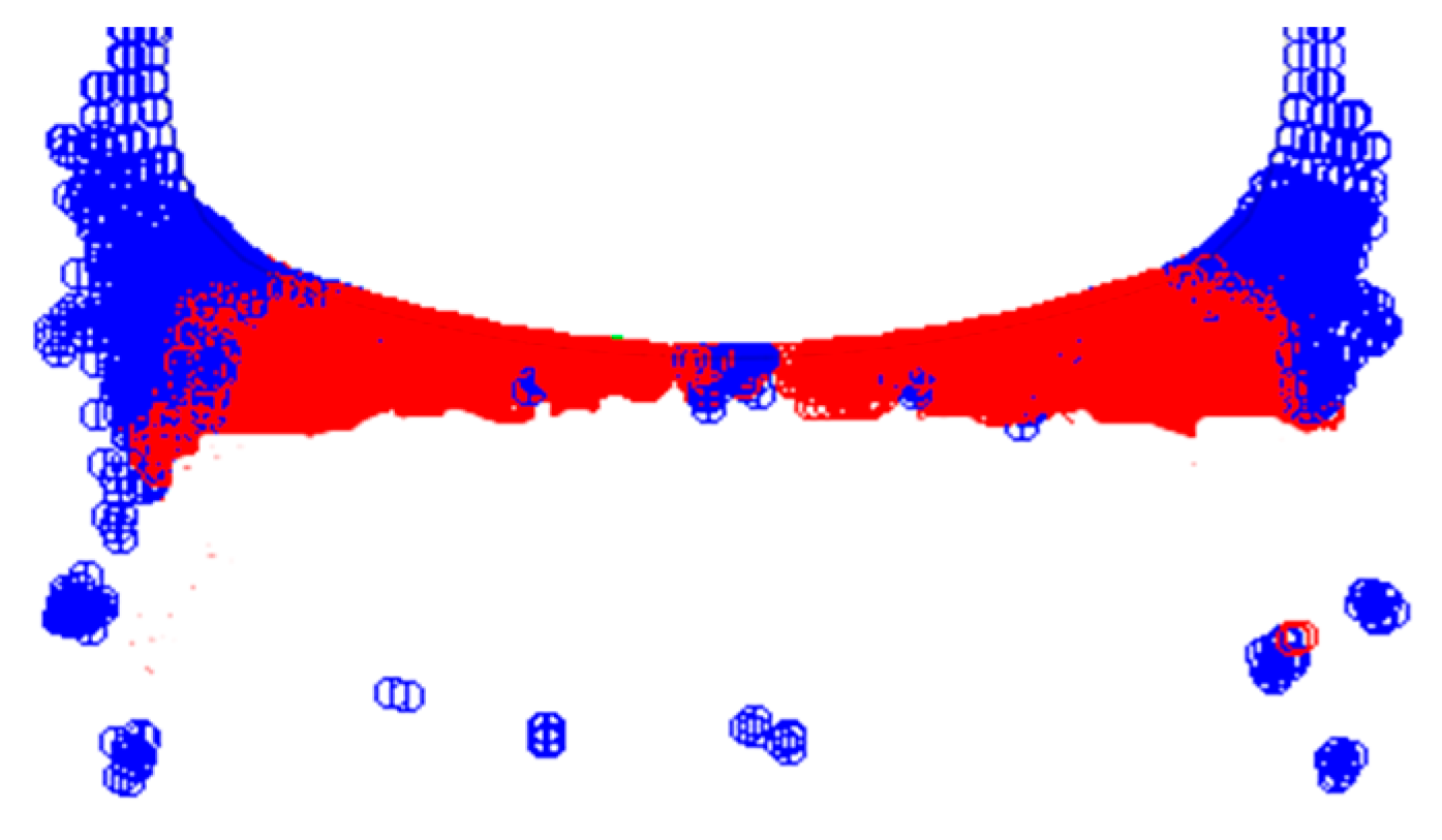
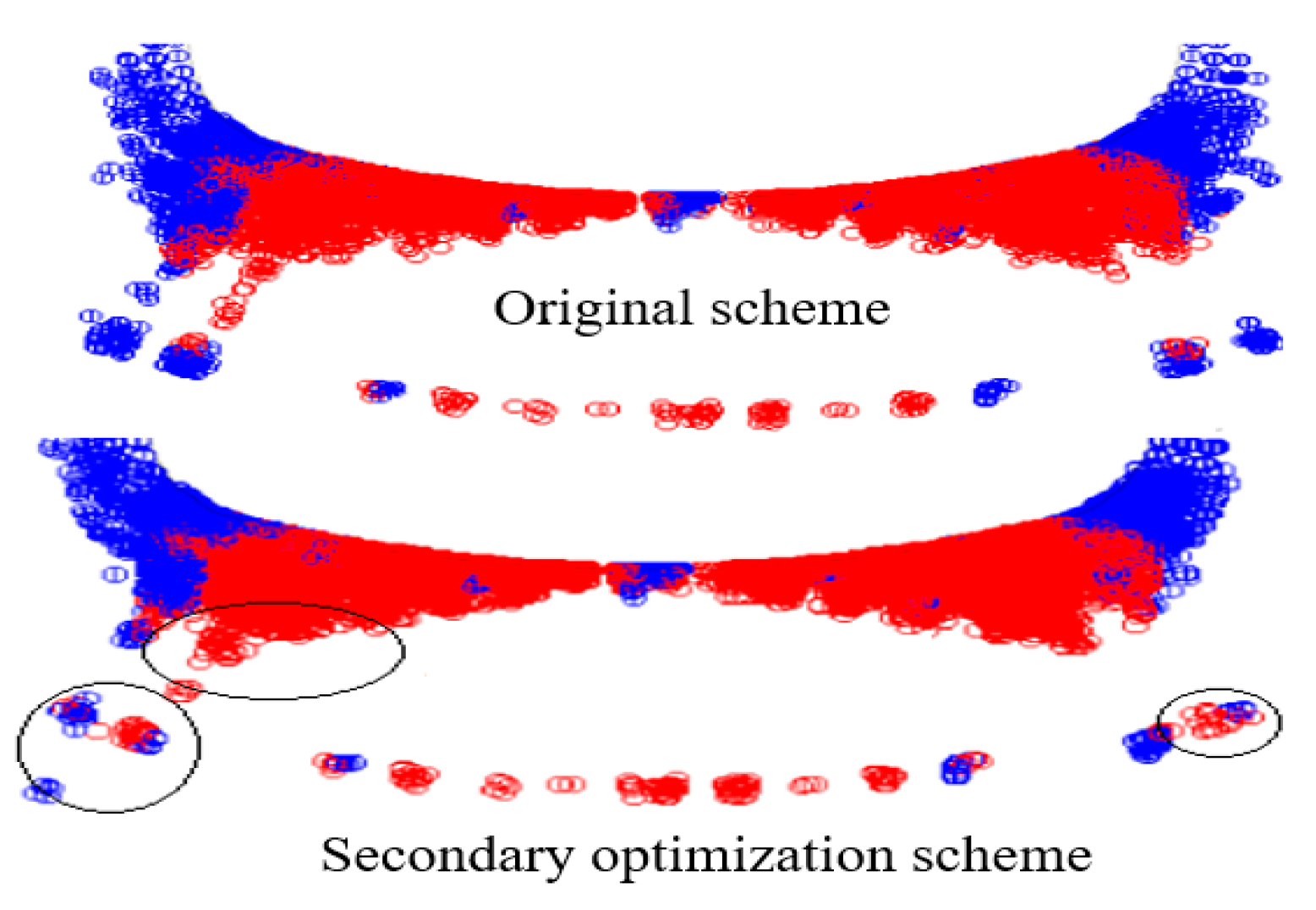
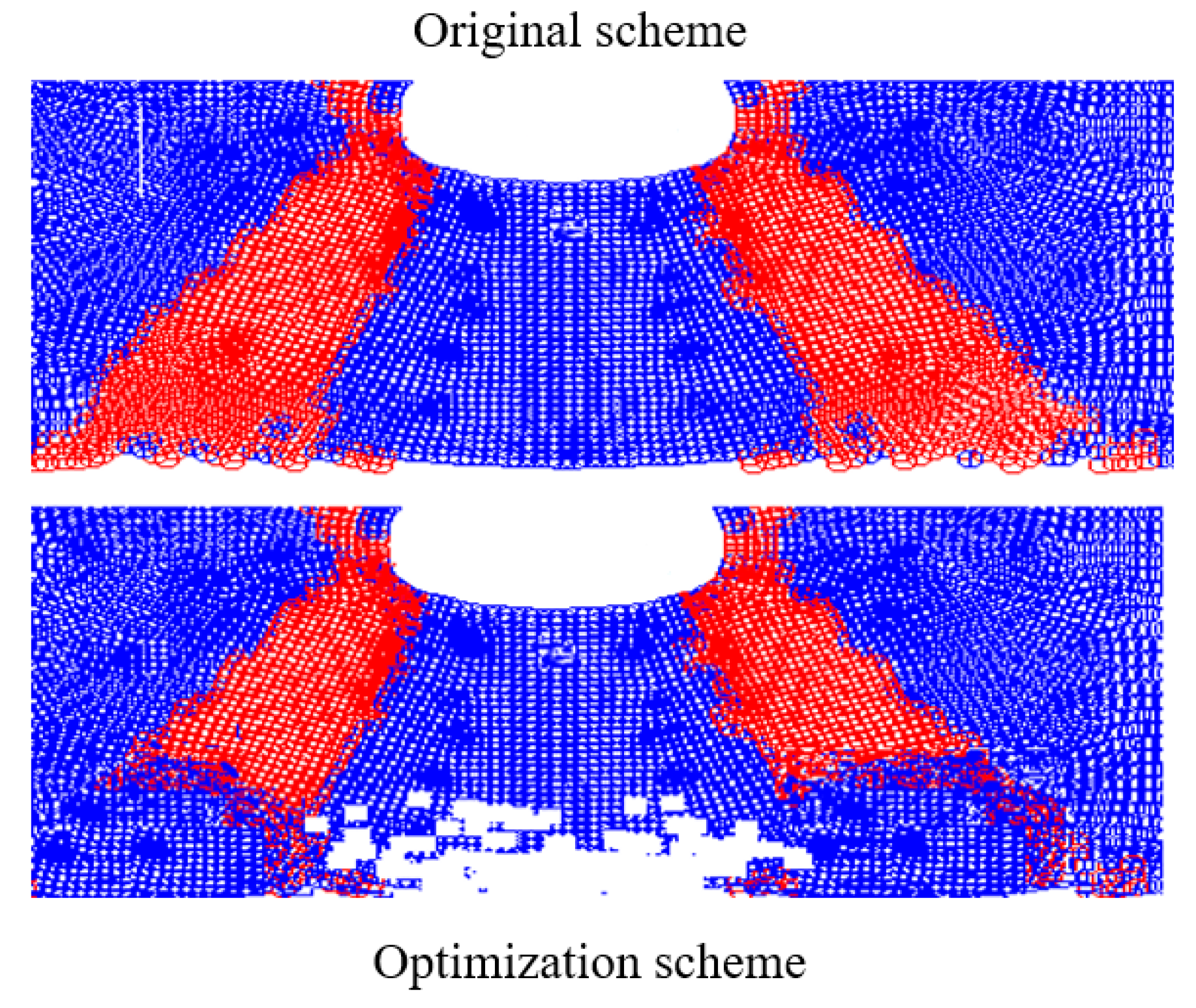
It can be seen from the above that increasing the pile length can significantly reduce the uplift displacement of the foundation, so the uneven settlement of the foundation can be controlled by increasing the pile length (Figure 12 and Figure 13). After the tunnel excavation, the plastic zone extends from the tunnel to the deep surrounding rock. When the pile length is the same, the depth of the plastic zone (red range) at the foot of the wall is about 5 m (Figure 14), and the depth of the plastic zone at the optimized foot of the wall is about 3 m (Figure 15). The differential settlement of the tunnel bottom 3 m away from the lining is extracted for comparative analysis, as shown in Figure 15. Under the combined action of the long pile and short pile, the range of the plastic zone at the depth of 3 m at the tunnel bottom is significantly reduced. The distribution of the plastic zone of the foundation can be obviously reduced and the self-bearing capacity of the surrounding rock can be fully exerted by using long piles and short piles to strengthen the foundation.
Designers are prone to make mistakes when choosing long and short piles, they deem that the plastic zone of the wall foot is large and the stress is large. Therefore, the piles at the foot of the wall shall be increased appropriately to reduce the plastic zone at the arch foot. The plastic zone range is calculated by the finite element method (Figure 16). To analyze its control effect on uneven settlement, the pile length at the foot of the wall is increased to 12 m (Figure 17), and the original design pile length of other parts of the tunnel bottom is still 6 m.. According to the comparison of the plastic zone (red zone) before and after optimization in Figure 17, increasing the pile length at the foot of the wall cannot effectively reduce the plastic zone range at the foot of the wall, and the local plastic zone range increases, as shown in the black circle area in Figure 18.

4.2. Analysis of Post-Construction Differential Settlement Control

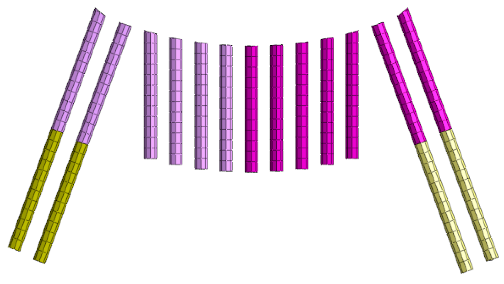
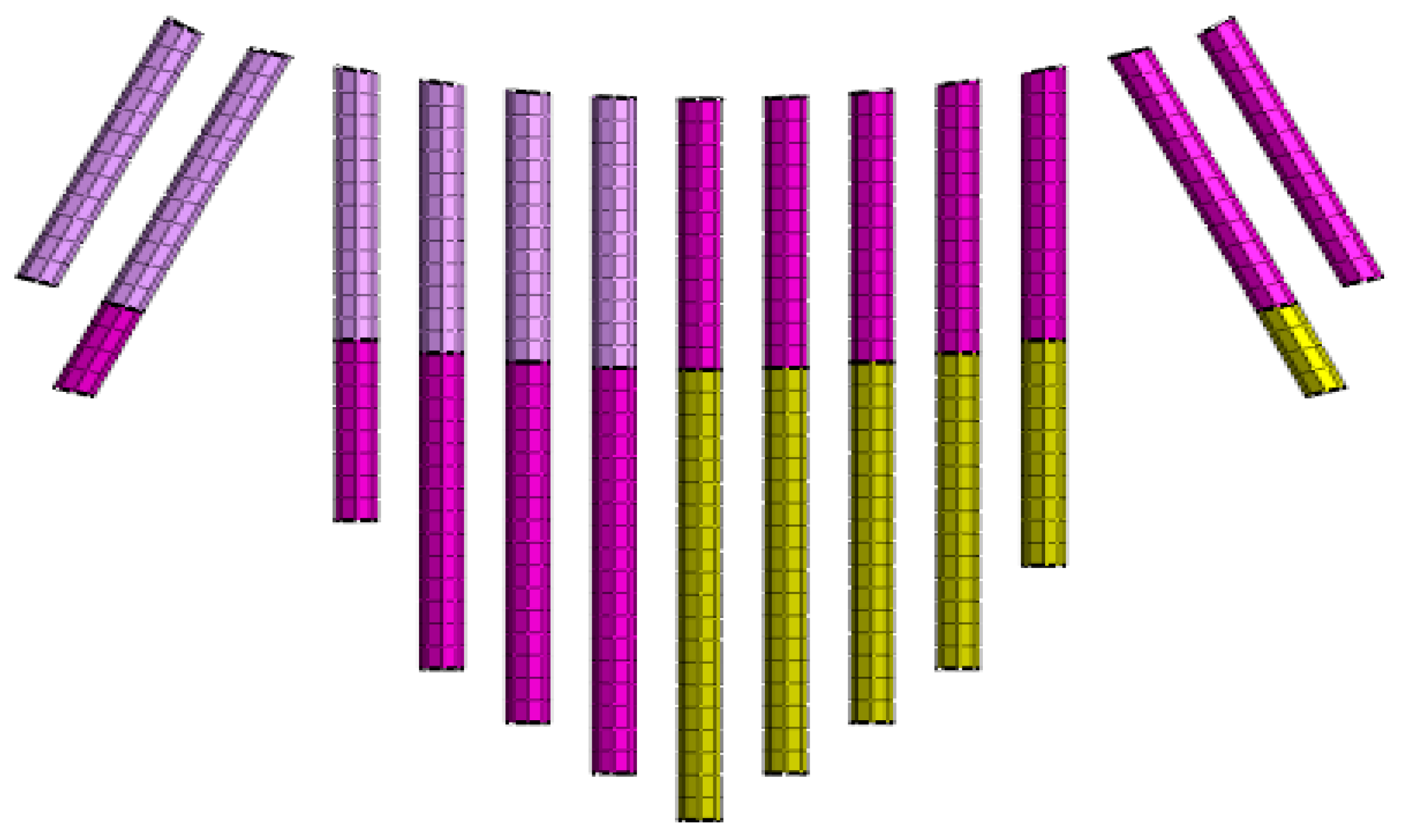
The control of uneven settlement after construction mainly refers to the control effect of the uneven settlement of the basement under unfavorable conditions of water immersion. According to the above analysis, the variable stiffness method has a poor control effect on uneven settlement, while the combination method of the long pile and the short pile has a better control effect on uneven settlement. Therefore, the combination method (Figure 19) is adopted to increase the pile length at large displacement and reduce the pile length at small displacement, and the plastic zone range (red zone) is compared, as shown in Figure 18. The calculated immersion depth is 20 m below the base. After optimization, the plastic zone of the deep basement is reduced from 20 m to 15 m. It can be seen that the combined method can significantly reduce the range of the plastic zone of the basement so that more soil in the basement can fully exert its self-bearing capacity, which is also very beneficial to restrain the overall settlement (Figure 20).

4.3. Evaluation of Reinforcement Effect

In the construction of a soft loess tunnel, the foundation will inevitably produce large uplift deformation. By increasing the pile length and replacement rate, the uplift displacement and post-construction settlement can be controlled in a small range. According to the construction concept of the New Austrian Tunneling Method (NATM) [26,27], the self-supporting capacity of surrounding rock should be fully mobilized and brought into play during construction. For the base position, the construction process of the upper soil mass is also the loading and unloading process of the soil mass at the bottom of the tunnel, and the base stress path is OEFGH (Figure 21). The OE section is the consolidation and settlement process of the basement under the action of gravity, the EFG section is the unloading and rebound process of the basement during tunnel excavation, the GH section is the elastic compression and deformation process of the basement under the action of surrounding rock and structural pressure, and the tunnel bottom settlement is the elastic compression and deformation of the GH section. Therefore, the deformation of the tunnel bottom is obviously different from the foundation deformation in the construction project [28,29]. The deformation of the tunnel bottom is mainly the elastic recompression deformation under the tunnel bottom pressure. Therefore, in the process of tunnel construction, the deformation of the surrounding rock at the tunnel bottom is elastic deformation, while in the excavation stage, the deformation of surrounding rock at the tunnel bottom is also elastic rebound deformation, and there will be no plastic damage at the tunnel bottom [30].
However, in the actual process of tunnel excavation, a large plastic deformation area will be generated from a certain depth range of the foundation, and the bearing capacity of the rock is a loss. The plastic zone in this part is mainly caused by the excessive differential settlement of the foundation, which leads to excessive local shear stress exceeding the shear strength of the soil mass, and finally leads to local shear failure of the tunnel bottom foundation [31]. Therefore, differential settlement control can be used as the evaluation index of the foundation reinforcement effect.

5. Conclusion

1. By changing the pile length of the jet grouting pile composite foundation and increasing the replacement rate, the uplift displacement and settlement under the unfavorable condition of tunnel bottom flooding can be controlled in a very small range.
2. The combination of long the pile and the short pile can significantly reduce the uneven settlement and plastic zone of the loess tunnel foundation.
3. The plastic failure of soil mass at the bottom of the loess tunnel is mainly caused by uneven settlement, and a 9 mm uneven settlement can be used as the evaluation index of the composite foundation reinforcement effect of the loess tunnel.

Author Contributions

Conceptualization, L.L.; Validation, J.Z.; Data curation, K.H.; Writing—original draft preparation, Z.L.; Supervision, Y.L. All authors have read and agreed to the published version of the manuscript.

Funding

China University Innovation Fund (2021DZ023); Weifang Science and Technology Development Plan (2021GX005).

Institutional Review Board Statement

Not applicable.

Informed Consent Statement

Not applicable.

Data Availability Statement

We declare that we have no financial and personal relationships with other people or organizations that can inappropriately influence our work, there is no professional or other personal interest of any nature or kind in any product, service and/or company that could be construed as influencing the position presented in, or the review of, the manuscript entitled.

Conflicts of Interest

The authors declare no conflict of interest.

References

  1. Zhu, H.Y.; Chen, J.X.; Luo, Y.B.; Li, Y.; Shi, Z.; Liu, W.W.; Wu, Y.F. The angle for setting foot reinforcement bolt based on the failure mode of shallow tunnel in loess. Tunn. Undergr. Space Technol. 2021, 108, 103689. [Google Scholar] [CrossRef]
  2. Ma, E.; Lai, J.; Xu, S.; Shi, X.; Zhang, J.; Zhong, Y. Failure analysis and treatments of a loess tunnel being constructed in ground fissure area. Eng. Fail. Anal. 2022, 134, 106034. [Google Scholar] [CrossRef]
  3. Assallay, A.M.; Rogers, C.D.F.; Smalley, I.J. Formation and collapse of metastable particle packings and open structures in loess deposits. Eng. Geol. 1997, 48, 101–115. [Google Scholar] [CrossRef]
  4. Haeri, S.M.; Khosravi, A.; Garakani, A.A.; Ghazizadeh, S. Effect of soil structure and disturbance on hydromechanical behavior of collapsible loessial soils. Int. J. Geomech. 2017, 17, 04016021. [Google Scholar] [CrossRef]
  5. Qiu, J.; Liu, H.; Lai, J.; Lai, H.; Chen, J.; Wang, K. Investigating the long-term settlement of a tunnel built over improved loessial foundation soil using jet grouting technique. J. Perform. Constr. Facil. 2018, 32, 04018066. [Google Scholar] [CrossRef]
  6. Sharifzadeh, M.; Kolivand, F.; Ghorbani, M.; Yasrobi, S. Design of sequential excavation method for large span urban tunnels in soft ground–Niayesh tunnel. Tunn. Undergr. Space Technol. 2013, 35, 178–188. [Google Scholar] [CrossRef]
  7. Kruse, G.A.; Dijkstra, T.A.; Schokking, F. Effects of soil structure on soil behaviour: Illustrated with loess, glacially loaded clay and simulated flaser bedding examples. Eng. Geol. 2007, 91, 34–45. [Google Scholar] [CrossRef]
  8. Jian-Guo, Y.; Yong-Li, X.; Yun-Zhou, W.; Wei, M. Pre-supporting with horizontal piles of jet grouting in weak loess tunnel. In Proceedings of the 2009 International Conference on Information Management, Innovation Management and Industrial Engineering, Xi’an, China, 26–27 December 2009; IEEE: Piscataway, NJ, USA, 2009; Volume 4, pp. 141–144. [Google Scholar]
  9. Huang, C.; Zhou, K.; Deng, B.; Li, D.; Song, Q.; Su, D. Influence of construction of the following tunnel on the preceding tunnel in the reinforced soil layer. Appl. Sci. 2022, 12, 10335. [Google Scholar] [CrossRef]
  10. Sun, H.; Sun, W. Effect of soil reinforcement on tunnel deformation as a result of stress relief. Appl. Sci. 2019, 9, 1420. [Google Scholar] [CrossRef] [Green Version]
  11. Huang, M.; Zou, C.; Meng, Z. The influence of different grouting methods on the surface environment of short clear distance tunnel. IOP Conf. Ser. Earth Environ. Sci. 2020, 510, 052063. [Google Scholar] [CrossRef]
  12. Zhao, H.H.; Chen, G.X.; Ye, B. Research on the deformation of single pile induced by adjacent shield driving. Chin. J. Undergr. Eng. 2010, 6, 794–802. [Google Scholar]
  13. Han, K.; Ju, J.W.W.; Kong, H.; Wang, M. Functional catastrophe analysis of progressive failures for deep tunnel roof considering variable dilatancy angle and detaching velocity. Rock Mech. Rock Eng. 2019, 52, 3987–3997. [Google Scholar] [CrossRef]
  14. Han, K.; Wang, L.; Su, D.; Hong, C.; Chen, X.; Lin, X.T. An analytical model for face stability of tunnels traversing the fault fracture zone with high hydraulic pressure. Comput. Geotech. 2021, 140, 104467. [Google Scholar] [CrossRef]
  15. Zhu, Y.P.; Du, X.Q.; Yang, X.H.; Li, H.J. Research on utility tunnel foundation treated by compaction piles and post-work immersion test in self-weight collapsible loess area with large thickness. Acad. Sin. 2019, 40, 2914–2924. [Google Scholar] [CrossRef]
  16. Li, Y.; Xu, S.; Liu, H.; Ma, E.; Wang, L. Displacement and stress characteristics of tunnel foundation in collapsible loess ground reinforced by jet grouting columns. Adv. Civ. Eng. 2018, 2018, 2352174. [Google Scholar] [CrossRef]
  17. Dapeng, L.; Xiaohua, Y.; Zhengjun, M. Research on high-pressure chemical churning pile in loess tunnel foundation reinforcement. In Proceedings of the 2013 Fourth International Conference on Digital Manufacturing & Automation, Shinan, China, 29–30 June 2013; IEEE: Piscataway, NJ, USA, 2013; pp. 1058–1060. [Google Scholar]
  18. Wu, B.; Zhang, Z.; Huang, W. Comparison and selection of reinforcement schemes for shield tunnelling close crossing high-speed railway viaduct group. IOP Conf. Ser. Earth Environ. Sci. 2019, 267, 042119. [Google Scholar] [CrossRef]
  19. Li, Z.; Chen, Z.; Wang, L.; Zeng, Z.; Gu, D. Numerical simulation and analysis of the pile underpinning technology used in shield tunnel crossings on bridge pile foundations. Undergr. Space 2021, 6, 396–408. [Google Scholar] [CrossRef]
  20. Li, Y.Y.; Xie, K.; Sun, Y.M.; Li, S.H.; An, X.H. Stress and deformation analysis and reinforcement time selection of composite foundations in shallow loess tunnels. Chin. J. Rock Mech. Eng. 2019, 38, 2332–2343. [Google Scholar]
  21. Xue, X.H.; Su, Z.M.; Sun, Z.J.; Song, F. Instability mechanism and supporting measure for highway tunnel with high ground stress and soft surrounding rock. Adv. Mater. Res. 2014, 1049, 213–216. [Google Scholar] [CrossRef]
  22. Peng, Z.Y.; Liu, W.N.; Zeng, Q.L. Research on pre-reinforcing composite foundation with a shield tunnel under-passing. Adv. Mater. Res. 2011, 243, 3556–3559. [Google Scholar] [CrossRef]
  23. Huang, S.; Chen, Z.; Xie, Y.; Lin, Z. A variational approach to the analysis of excavation-induced vertical deformation in a segmental tunnel. Tunn. Undergr. Space Technol. 2022, 122, 104342. [Google Scholar] [CrossRef]
  24. Sun, H.; Zhang, J.; Zhao, G.; Wang, H. Tunnel behaviour caused by basement excavation in clay. Geofluids 2021, 2021, 5570846. [Google Scholar] [CrossRef]
  25. Chen, B.; Wen, Z. Elasto-plastic analysis for the effect of longitudinal uneven settlement on shield tunnel. In (RE) Claiming the Underground Space; Routledge: London, UK, 2003; pp. 969–974. [Google Scholar]
  26. Aygar, E.B. Evaluation of new Austrian tunnelling method applied to Bolu tunnel’s weak rocks. J. Rock Mech. Geotech. Eng. 2020, 12, 541–556. [Google Scholar] [CrossRef]
  27. Wu, R.; Fujita, Y.; Soga, K. Integrating domain knowledge with deep learning models: An interpretable AI system for automatic work progress identification of NATM tunnels. Tunn. Undergr. Space Technol. 2020, 105, 103558. [Google Scholar] [CrossRef]
  28. Sun, Z.; Zhang, D.; Fang, Q.; Dui, G.; Chu, Z. Analytical solutions for deep tunnels in strain-softening rocks modeled by different elastic strain definitions with the unified strength theory. Sci. China Technol. Sci. 2022, 65, 2503–2519. [Google Scholar] [CrossRef]
  29. Liu, L.; Li, Z.; Liu, X.; Li, Y. Frost front research of a cold-region tunnel considering ventilation based on a physical model test. Tunn. Undergr. Space Technol. 2018, 77, 261–279. [Google Scholar] [CrossRef]
  30. Sun, Z.; Zhang, D.; Fang, Q.; Huangfu, N.; Chu, Z. Convergence-confinement analysis for tunnels with combined bolt–cable system considering the effects of intermediate principal stress. Acta Geotech. 2022, 1–26. [Google Scholar] [CrossRef]
  31. Liu, L.; Cai, G.; Zhang, J.; Liu, X.; Liu, K. Evaluation of engineering properties and environmental effect of recycled waste tire-sand/soil in geotechnical engineering: A compressive review. Renew. Sust. Energ. Rev. 2020, 126, 109831. [Google Scholar] [CrossRef]
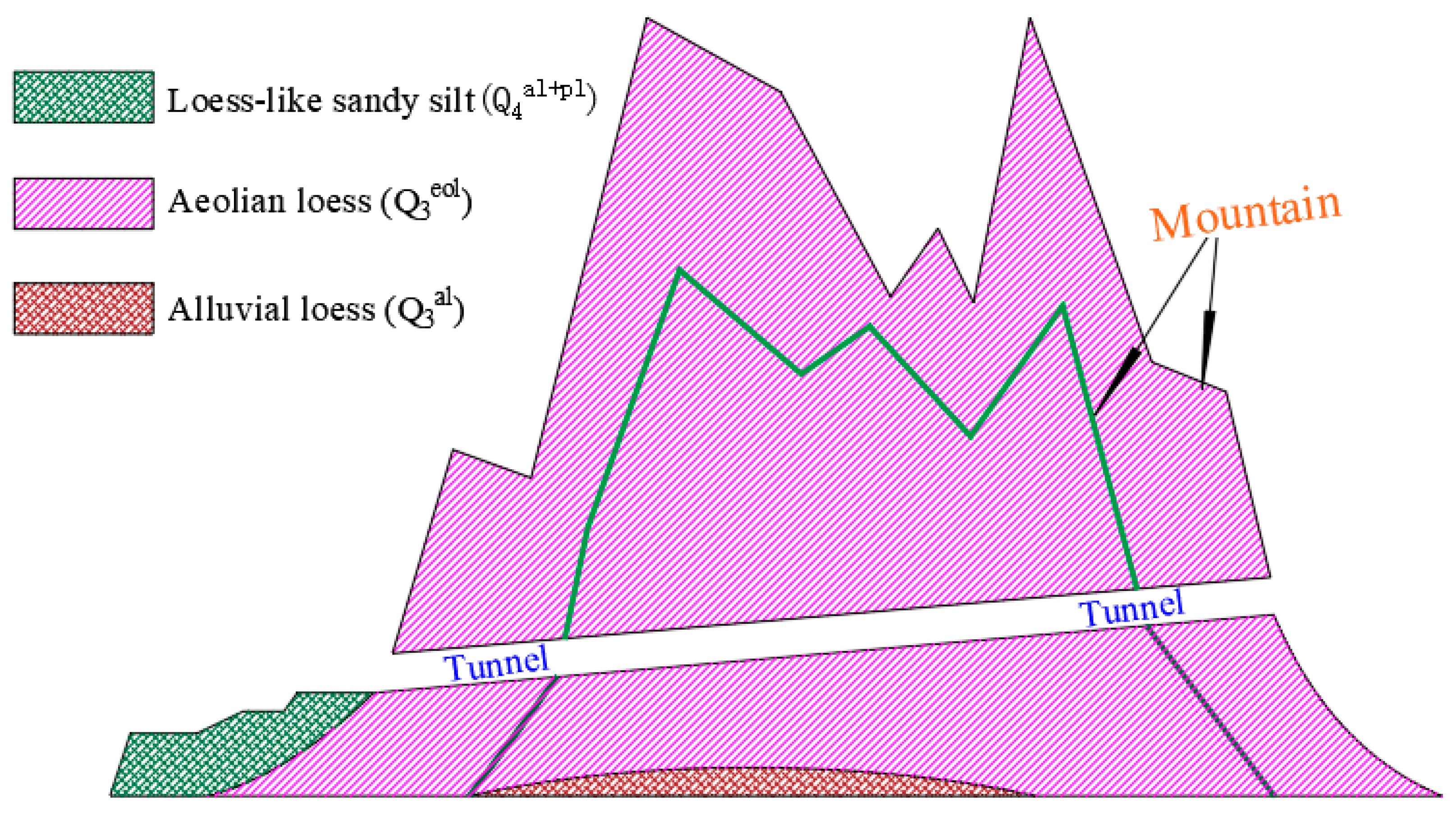
Figure 1. Geological condition of the site.
Applsci 13 01570 g001
Figure 2. Fabrication of model groove: (a) Test trench; (b) Pit side support frame; (c) Glass retaining wall; (d) Frame support Figure.
Applsci 13 01570 g002
Figure 3. Fabrication of surrounding rock: (a) Production of mixture; (b) Collapsibility test; (c) Compaction process; (d) Sampling.
Applsci 13 01570 g003
Figure 4. Finite element numerical model: (a) Computational model; (b) Rotary jet pile model.
Applsci 13 01570 g004
Figure 5. The opportunity of jet grouting pile reinforcement: (a) Embedded type; (b) Twice application; (c) Once application; (d) Layout after excavation.
Applsci 13 01570 g005
Figure 6. Location of displacement monitoring points.
Applsci 13 01570 g006
Figure 7. Radial displacement of base and side wall (different reinforcement times).
Applsci 13 01570 g007
Figure 8. Soil displacement of base and side wall (different replacement rates).
Applsci 13 01570 g008
Figure 9. Soil displacement of base and side wall (different pile lengths).
Applsci 13 01570 g009
Figure 10. The additional stress of base: (a) No pile arrangement; (b) The pile length is 6 m; (c) The pile length is 11 m; (d) The pile length is 15 m.
Applsci 13 01570 g010
Figure 11. Variation law of base settlement under different replacement rates and pile lengths: (a) Replacement rate; (b) Pile length.
Applsci 13 01570 g011
Figure 12. Layout of foundation pile.
Applsci 13 01570 g012
Figure 13. Differential settlement of foundation base under different stiffness.
Applsci 13 01570 g013
Figure 14. Plastic zone of the original scheme.
Applsci 13 01570 g014
Figure 15. Plastic zone of optimization scheme.
Applsci 13 01570 g015
Figure 16. Differential settlement under different schemes.
Applsci 13 01570 g016
Figure 17. Optimized pile length.
Applsci 13 01570 g017
Figure 18. Plastic zone.
Applsci 13 01570 g018
Figure 19. Optimized pile length.
Applsci 13 01570 g019
Figure 20. Comparison of the plastic zone before and after optimization.
Applsci 13 01570 g020
Figure 21. Geotechnical deformation mechanism.
Applsci 13 01570 g021
Table 1. Statistics of diseases at the bottom of some operating loess tunnels in China [5].
NumberRoute NameTunnel NameLengthDistress LocationDistress Condition
1Shenmu-ShuozhouShekoumao5804Arch wall, tunnel
Foundation, ballast bed
Cracks occurred on the arch wall; ponding in the tunnel bottom; cracking of tunnel bottom and channel; subsidence of ballast bed
2Shenmu-ShuozhouHuojialiang4722Tunnel foundation, ballast bedMud pumping of foundation; subsidence of ballast bed
3G312Qijiadashan860Lining, pavementCracks occurred on the pavement and lining
4Baotou-Xi’anMaotianshan14,915Ballast, ballast bedLarger deformation occurred on the ballast bed; mud pumping of the foundation
5Baotou-Xi’anTongmushi8282Tunnel foundationWater emitting caused by cushion cracks
6Baotou-Xi’anJiuyanshan9353Ballast bedMud pumping induced by cushion cracks
7Baotou-Xi’anSizehe7655Ballast bedMud pumping of foundation; subsidence of ballast bed
8Taiyuan-YinchuanHengshan11,448Tunnel foundationCracks occurred on the cushion
9Taiyuan-YinchuanXingwangmao11,055Tunnel foundationCracks occurred on the cushion; mud pumping of the foudation
10Xi’an-Yan’anLingjiachuan1137Tunnel foundationWater emitting caused by cushion cracks
Note: (Unit: m).
Table 2. Mechanical parameters of model structure materials.
StructureElastic Modulus E (MPa)Poisson’s ratio μWeight γ
kN/cm3
Collapsibility Coefficient δsCompressive Strength Rc (MPa)
Surrounding rock structure1.30.315.20.043——
Lining structure33000.38————25
Jet grouting pile2600.25————0.315
Table 3. Physical and mechanical parameters of materials.
MaterialWeight γ
(KN/cm3)
Elastic Modulus E (GPa)Poisson’s Ratio μCohesion c (kPa)Internal Friction Angle φ (°)
Q 3 eol Loess15.20.0520.322028
Lining structure17.23.30.38————
Jet grouting pile2010.40.25————
Disclaimer/Publisher’s Note: The statements, opinions and data contained in all publications are solely those of the individual author(s) and contributor(s) and not of MDPI and/or the editor(s). MDPI and/or the editor(s) disclaim responsibility for any injury to people or property resulting from any ideas, methods, instructions or products referred to in the content.