
Dynamic Simulation Analysis of the Working Process of the Picking Mechanism of a Sugarcane Leaf Cutting and Returning Machine


Abstract
:1. Introduction
2. Materials and Methods
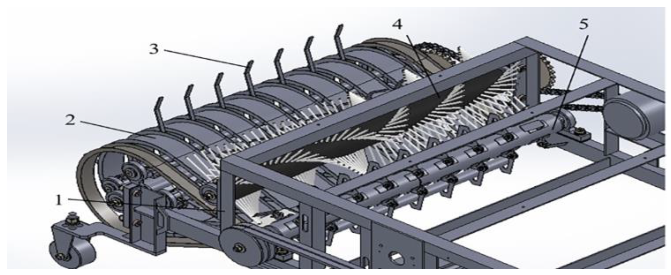
2.1. Working Mechanism of the Returning Machine
2.2. Three-Dimensional and Finite Element Modelling
2.2.1. Three-Dimensional Model of the Picking System
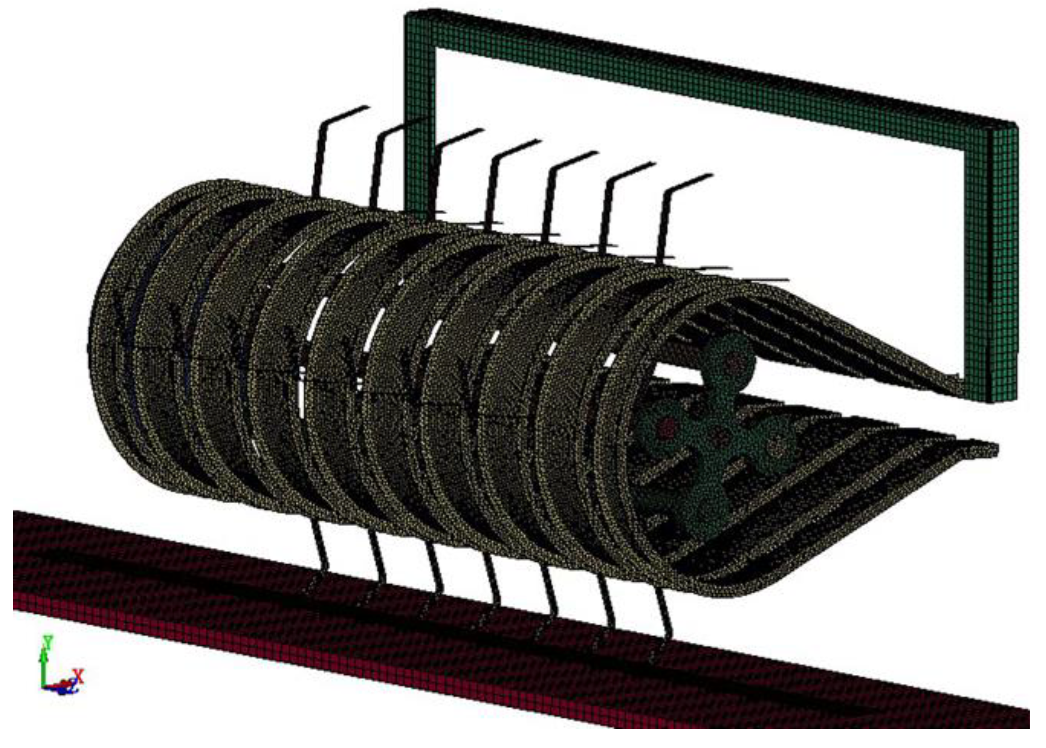
2.2.2. Finite Element Model of the Picking System
3. Simulation and Analysis of the Sugarcane Leaf-Picking Process
3.1. Analysis of the Working Process of the Pick-up Mechanism
3.2. Analysis of Sugarcane Leaf Posture Picking Process
3.3. Analysis of Stress Change of Elastic Teeth
3.4. Analysis of Changes in the Sugarcane Leaf Bending Angle
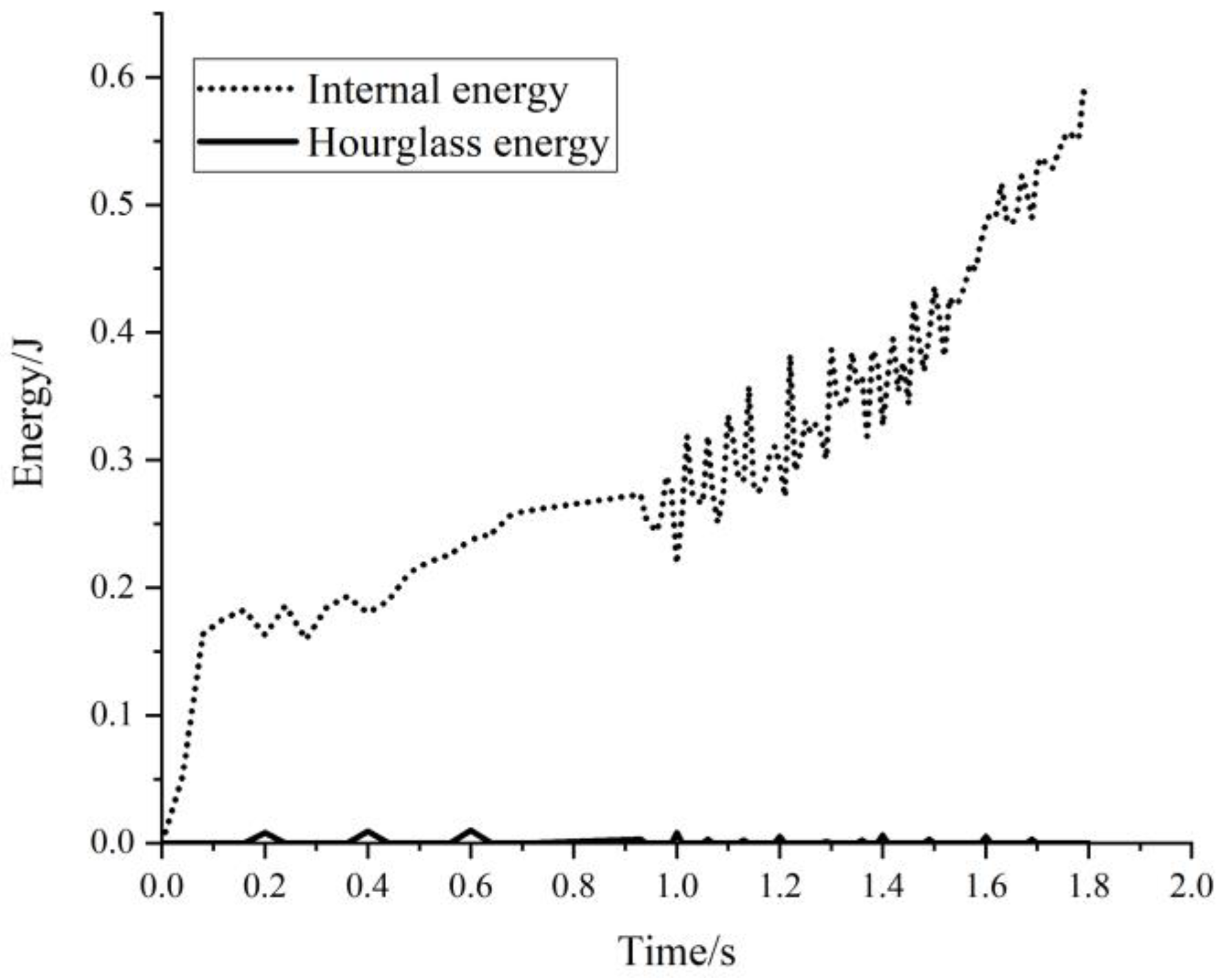
3.5. Hourglass Energy–Time Curve
4. Experiment and Analysis
4.1. Experimental Programme
4.2. Experimental Results and Analysis
4.2.1. Analysis of Sugarcane Leaf Posture Changes
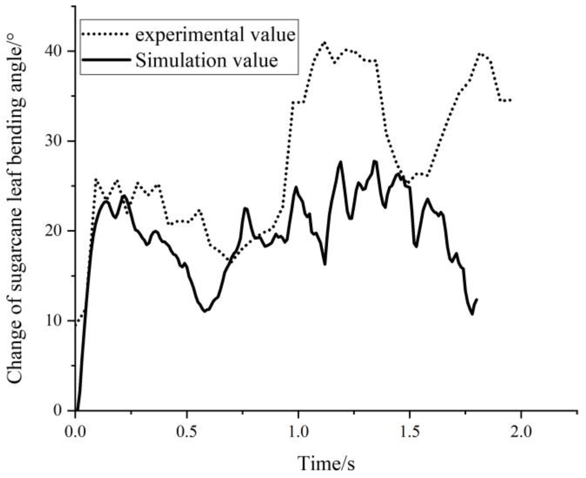
4.2.2. Analysis of Changes in Sugarcane Leaf Bending Angle
5. Conclusions
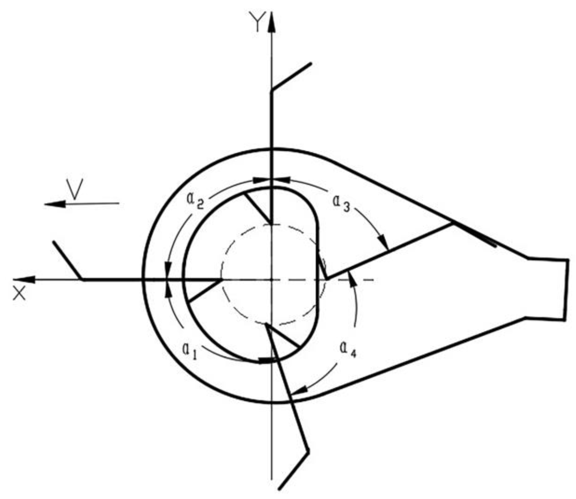
- (1)
- The working process of the elastic teeth roller picking mechanism was analyzed. The rotary position relationship of the roller plate corresponding to the posture change of the elastic teeth in the movement process was defined as the pick-up phase of the elastic teeth, which is expressed by the rotation angle of the roller plate. The changes in the movement of the elastic teeth during a cycle can be divided into four stages, namely the pick-up stage, the lift-up stage, the push-up stage and the retraction stage. Each of these four stages corresponds to the phase angle of the corresponding elastic teeth.
- (2)
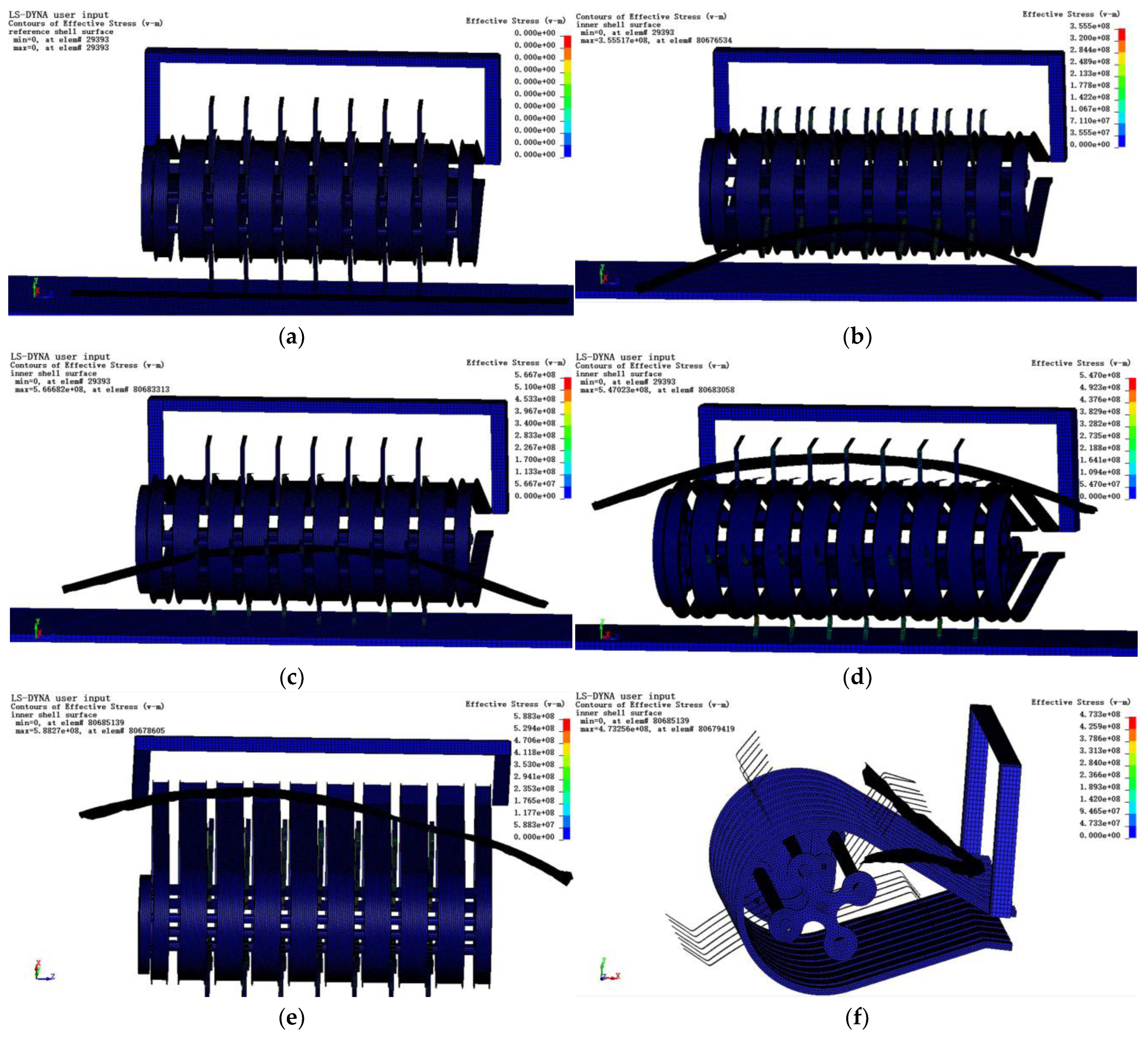
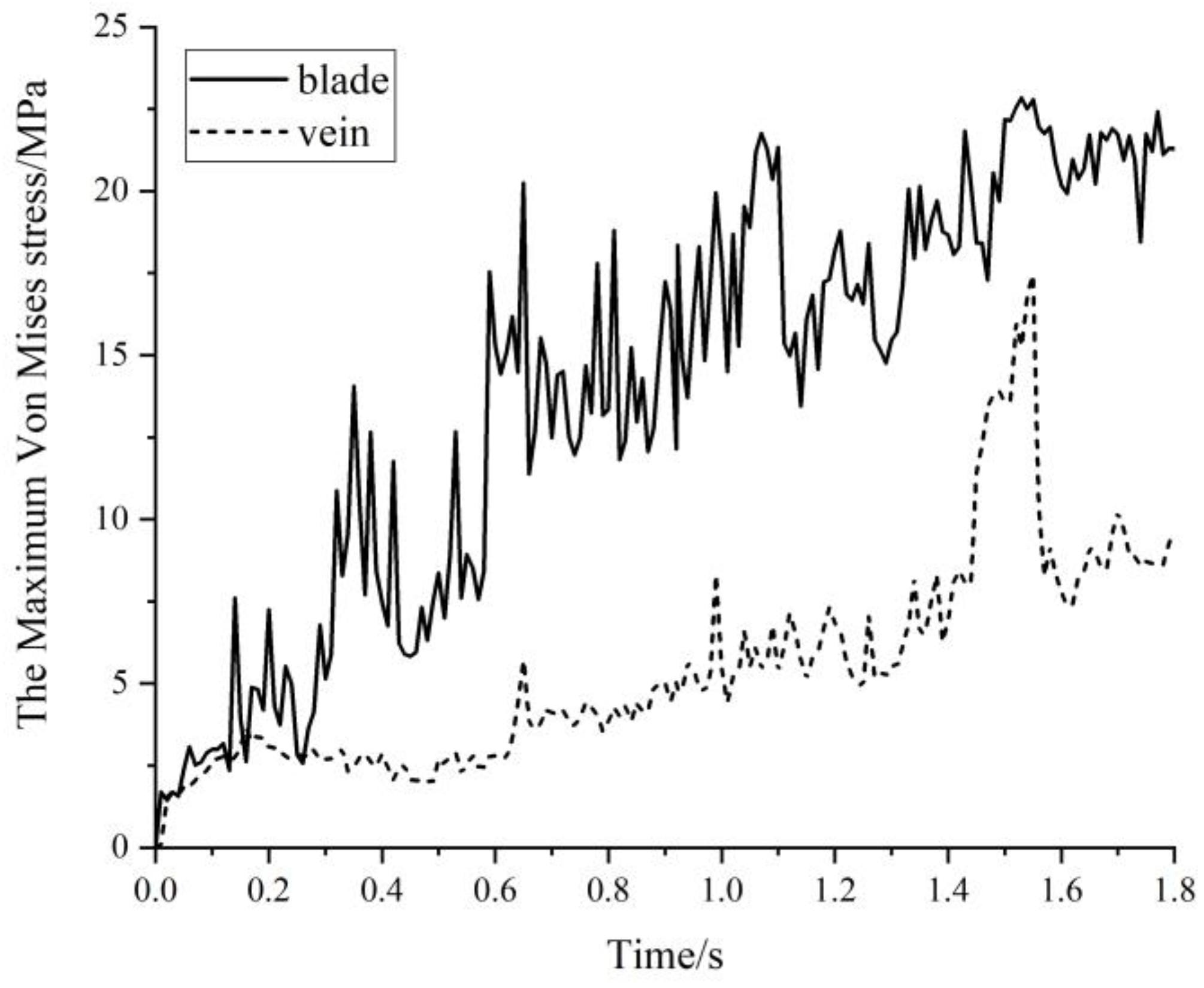
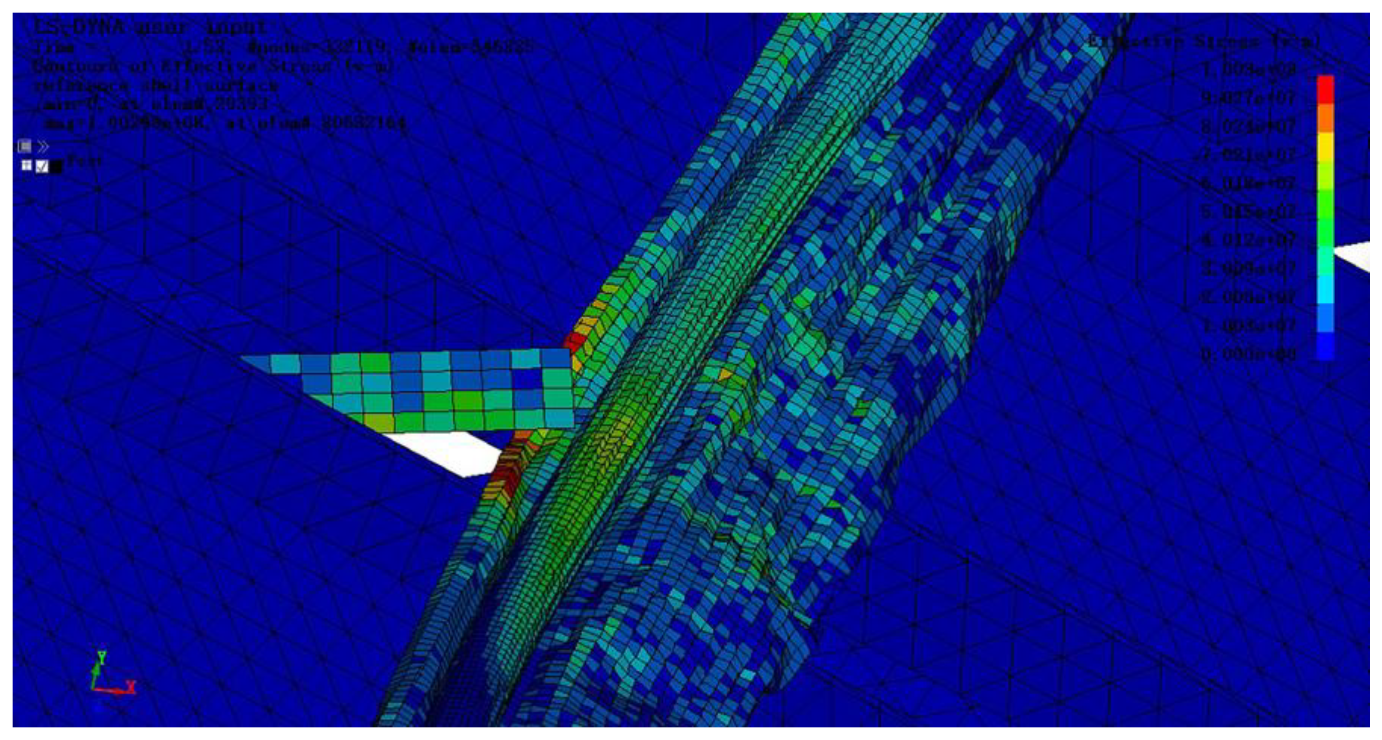
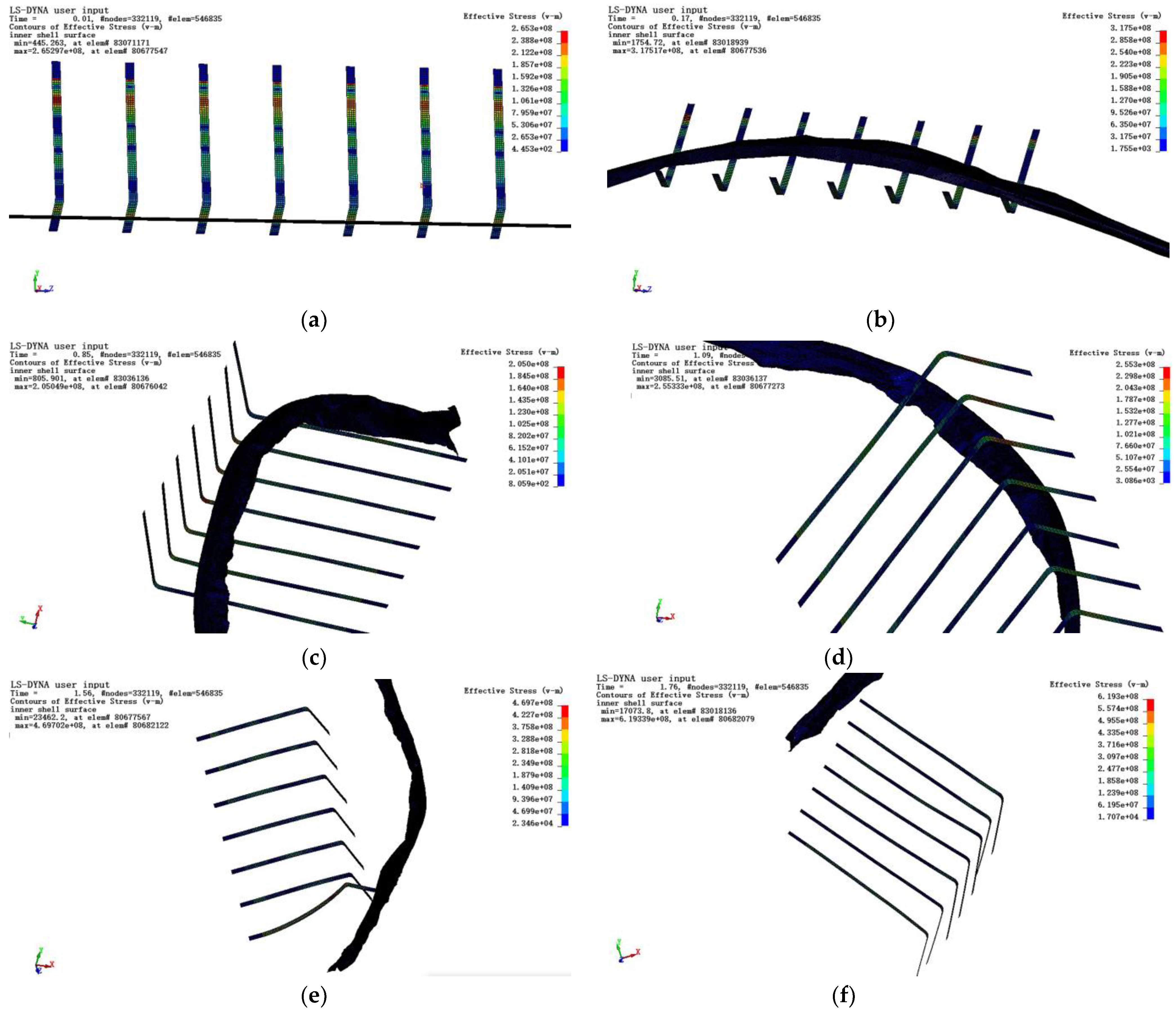
- A detailed analysis of sugarcane leaf postures, stresses, bending angles and stresses in the elastic teeth was carried out. The results showed that the posture changes of sugarcane leaves during picking were a “C”, a logarithmic curve, a wavy shape and a “V” shape in turn. The maximum Von Mises stress of sugarcane blade and vein during picking was 22.8 MPa and 17.5 MPa, respectively. The sugarcane leaf showed minor breakage during the picking process, while the vein remained undamaged. The evaluation criterion of the bending angle was creatively put forward to measure the bending deformation of leaves. The overall bending angle of the sugarcane leaf first increased rapidly, then decreased gradually, then increased in a fluctuating way , and finally fluctuated within an interval of 15 degrees’ difference. The maximum Von Mises stress of elastic teeth during picking was 900 MPa. The elastic teeth do not fail during the picking process, and the multi-segment linear plasticity model can be used to simulate the deformation of the elastic teeth.
- (3)
- The results of the quick camera experiment were in good agreement with those of simulation analysis, which indicated that the simulation model is reliable and effective in analyzing the process of the picking up of sugarcane leaf by the picking mechanism. The change in the posture of the sugarcane leaf and the bending angle in the experiment were consistent with the simulation analysis. The trend for both the experimental and simulated sugarcane leaf bending angles was a four-stage process, with an overall rapid increase followed by a gradual decrease, then a fluctuating increase and finally, a fluctuating change within the interval of 15 degrees’ difference. The trend of the bending angle was the same for both the experiment and simulation. The correlation coefficient between the experiment curve and the simulation curve was 0.557. The experimental and simulation values of the average sugarcane leaf bending angle were 27°and 19°, respectively. The relative error of the average bending angle was 29.6%. The reason for the large relative error is that the moisture content of the sugarcane leaf in the simulation and the moisture content of the actual sugarcane leaf cannot be guaranteed to be identical.
Author Contributions
Funding
Institutional Review Board Statement
Informed Consent Statement
Data Availability Statement
Acknowledgments
Conflicts of Interest
References
- National Bureau of Statistics of China. China Statistics Yearbooks; China Statistics Press: Beijing, ChiWna, 2021. [Google Scholar]
- Xiao, W.; Lu, J.P. Analysis of the current status of mechanised sugarcane harvesting technology. J. Chin. Agric. Mech. 2022, 43, 50–59, 142. [Google Scholar] [CrossRef]
- Galdos, M.V.; Cerri, C.C.; Cerri, C.E.P. Soil carbon stocks under burned and unburned sugarcane in Brazil. Geoderma 2009, 153, 347–352. [Google Scholar] [CrossRef]
- Huang, W.H.; Yan, X.L.; Dong, X.H.; Li, M.; Wei, L.J. Design and experiment on the 1GYFH type returning machine of grinding and mixed-buried sugarcane leaves. J. Agric. Mech. Res. 2018, 40, 140–144. [Google Scholar] [CrossRef]
- Li, M.; Wang, J.L.; Deng, Y.G.; Huang, H.; Zhang, J.; Song, D.Q.; Lian, W.W. Structural design and experiments on sugarcane leaf shattering and returning machine. Trans. CSAE 2008, 24, 121–126. [Google Scholar] [CrossRef]
- Lu, J.M.; Li, M.; Wei, L.J.; Wang, J.L.; Song, D.Q.; Zhang, J.; Deng, Y.G. Optimized design of 1GYF-200 sugarcane leaf shattering and returning machine’s cutter roller. Appl. Mech. Mater. 2011, 120, 172–177. [Google Scholar] [CrossRef]
- Dai, H.Y.; Wang, Y.X.; Wen, F.J.; Tang, Y.Q. Analysis and experiment of flow field in sugarcane leaf cutting and returning machine. IOP Conf. Ser. Mater. Sci. Eng. 2020, 735, 012079. [Google Scholar] [CrossRef]
- Qiu, Z.G.; Wang, Y.X.; Tang, Y.Q.; Luo, W.H.; Ye, Z.L. Analysis of blockage and wrapping by leaves in the cutting mechanism of a sugarcane leaf shredder. Biosyst. Eng. 2021, 211, 152–166. [Google Scholar] [CrossRef]
- Cui, T.; Liu, J.; Zhang, D.X.; Shi, S. Flexible body simulation for corn stem based on ANSYS and ADAMS. Trans. Chin. Soc. Agric. Mach. 2012, 43, 112–115. [Google Scholar] [CrossRef]
- Peng, T.; Han, Y.; Zhai, D. Study on numerical model of the collision effect between river ice and flexible high pier. Appl. Mech. Mater. 2015, 723, 65–70. [Google Scholar] [CrossRef]
- Park, Y.; Kim, Y.; Baluch, A.H.; Kim, C.-G. Numerical simulation and empirical comparison of the high velocity impact of STF impregnated Kevlar fabric using friction effects. Compos. Struct. 2015, 125, 520–529. [Google Scholar] [CrossRef]
- Xu, B.; Yang, Y.; Yan, Y.; Zhang, B. Bionics design and dynamics analysis of space webs based on spider predation. Acta Astronaut. 2019, 159, 294–307. [Google Scholar] [CrossRef]
- Xie, L.X.; Wang, J.; Cheng, S.M.; Yang, Z.Z.; Chen, B.S.; Huang, Y.Z. Simulation analysis and experiments of leaf stripping process for whole-stalk sugarcane harvesters. Trans. CSAE 2020, 36, 56–65. [Google Scholar] [CrossRef]
- Zhu, D.J.; Peng, L. Simulation and experiment of key influencing factors on ballistic performance of SiC-ultra-high molecular weight polyethylene biomimetic flexible laminated structure. Acta Mater. Compos. Sin. 2020, 37, 2928–2940. [Google Scholar] [CrossRef]
- Zhang, Y.Q.; Cui, Q.L.; Li, H.B.; Zhang, Z.Y.; He, Y.Q.; Sun, D. Simulation and experiment of cutting mechanical characteristics of millet stalk based on ANSYS. LS-DYNA INMATEH Agric. Eng. 2020, 61, 143–150. [Google Scholar] [CrossRef]
- Chen, J.N.; Zhou, B.S.; Jia, J.M.; Chen, Z.W.; Yu, C.N.; Cai, S.L. Design and parameters optimization of root cutting tool based on garlic numerical simulation model. J. Food Process Eng. 2021, 44, e13753. [Google Scholar] [CrossRef]
- Sreenivas, H.T.; Krishnamurthy, N.; Suprith, S.V. Investigating the crashworthiness of kenaf/kevlar hybrid composite frontal car fascia for low-velocity impact using LS-DYNA. J. Inst. Eng. Ser. D 2021, 102, 413–427. [Google Scholar] [CrossRef]
- Lam, H.W.K.; Sze, E.H.Y.; Wong, E.K.L.; Poudyal, S.; Ng, C.W.W.; Chan, S.L.; Choi, C.E. Study of dynamic debris impact load on flexible debris-resisting barriers and the dynamic pressure coefficient. Can. Geotech. J. 2022, 59, 2102–2118. [Google Scholar] [CrossRef]
- Weerasinghe, D.; Bambach, M.R.; Mohotti, D.; Wang, H.; Jiang, S.; Hazell, P.J. Development of a coated fabric armour system of aramid fibre and rubber. Thin Walled Struct. 2022, 179, 109679. [Google Scholar] [CrossRef]
- Luo, W.; Wang, Y.; Tang, Y.; Qiu, Z.; Zhao, Q.; Ren, G.; Ye, Z. Numerical simulation and experiment on wrapping characteristics between sugarcane leaves and rotating roller of returning machine. Comput. Electron. Agric. 2022, 202, 107441. [Google Scholar] [CrossRef]
- Lu, J.X.; Wang, Y.X.; Tang, Y.Q.; Xu, Z.H.; Zhao, F. Fatigue analysis of large-deformation cutting tool used in cutting-off sugarcane-leaf returning machine. Res. Appl. Mech. Eng. 2014, 3, 54–57. [Google Scholar]
- Wang, Y.J.; Sun, J.J.; Jiang, T.; Yang, C.; Tan, Q.; Guo, S.W.; Liu, Y.N. Super strength of 65Mn spring steel obtained by appropriate quenching and tempering in an ultrafine grain condition. Mater. Sci. Eng. 2019, 754, 1–8. [Google Scholar] [CrossRef]
- Zheng, Y.; Li, L.; Jiao, J.; Wang, J.L.; Ye, Y.W. Analysis of biomechanical properties of sugarcane leaves. Chin. J. Trop. Agric. 2017, 37, 84–88. [Google Scholar] [CrossRef]
- Liu, X.D. Numerical Simulation and Elasticback Control of Aluminum Alloy Sheet in Multi-point Forming. Master’s Thesis, Jilin University, Changchun, China, 2018. [Google Scholar]


| Parameters | Value |
|---|---|
| Radius of base circle (mm) | 41 |
| Radius of roller plate (mm) | 60 |
| Length of crank (mm) | 40 |
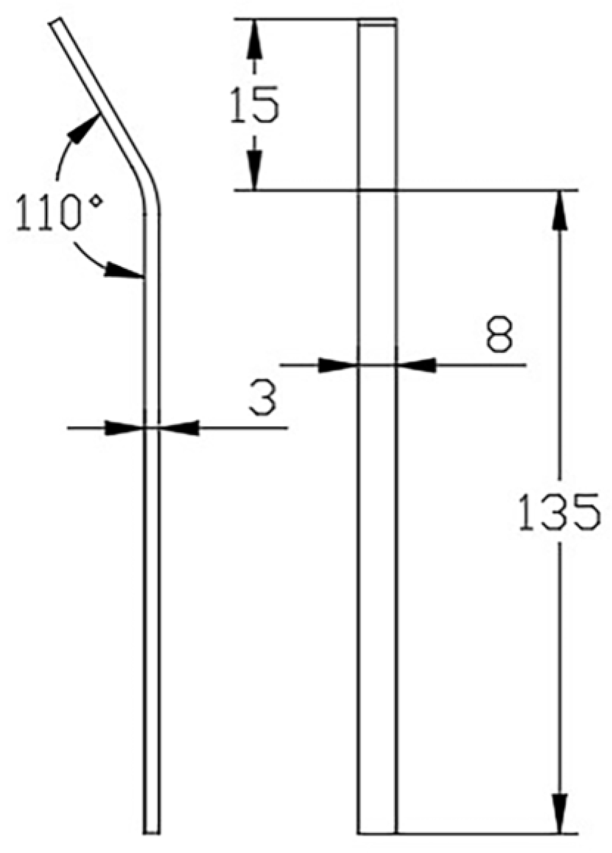
| Length of elastic tooth (mm) | 150 |
| Angle between elastic teeth and crank (°) | 52 |
| Three arc radius (mm) | 41/53/89 |
| Angle of upper guard plate (°) | 24 |
| Number of elastic tooth rod | 4 |
| Models | Parameter | Parameter Values |
|---|---|---|
| Leaf blade/leaf vein | Elastic modulus (MPa) | data 1281/716 |
| Shear modulus (MPa) | 493/272 | |
| Tensile strength (MPa) | 33/22 | |
| Shear strength (MPa) | 5.7/7.8 | |
| Poisson’s ration | 0.29/0.31 | |
| Hardening parameter | 0.0 | |
| Elastic teeth | Density (kg.m−3) | 7800 |
| Elastic modulus (Pa) | 2.0 × 10¹¹ | |
| Poisson’s ratio | 0.269 | |
| Guard plate, cam plate, power shaft, crank linkage, elastic tooth rod, roller wheel, roller plate, door frame, ground | Density (kg.m−3) | 7850 |
| Elastic modulus (Pa) | 2.1 × 10¹¹ | |
| Poisson’s ratio | 0.3 |
| Contact Model | Keywords | Static Friction Coefficient | Dynamic Friction Coefficient |
|---|---|---|---|
| Sugarcane leaf and elastic teeth | AUTOMATIC_SURFACE_TO_SURFACE | 0.6 | 0.58 |
| Sugarcane leaf and ground | AUTOMATIC_SURFACE_TO_SURFACE | 0.1 | 0.05 |
| Sugarcane leaf and guard plate | AUTOMATIC_SURFACE_TO_SURFACE | 0.1 | 0.05 |
| Sugarcane leaf and door frame | AUTOMATIC_SURFACE_TO_SURFACE | 0.1 | 0.05 |
| Sugarcane leaf and sugarcane leaf | AUTOMATIC_SIN- GLE _SURFACE | 0.1 | 0.05 |
| Roller plate and power shaft | AUTOMATIC_SURFACE_TO_SURFACE | 0.1 | 0.05 |
| Roller plate and elastic teeth rod | AUTOMATIC_SURFACE_TO_SURFACE | 0.1 | 0.05 |
| Crank linkage and roller wheel | AUTOMATIC_SURFACE_TO_SURFACE | 0.1 | 0.05 |
| Cam plate and roller wheel | AUTOMATIC_SURFACE_TO_SURFACE | 0.1 | 0.05 |
| Cam plate and power shaft | AUTOMATIC_SURFACE_TO_SURFACE | 0.1 | 0.05 |
Disclaimer/Publisher’s Note: The statements, opinions and data contained in all publications are solely those of the individual author(s) and contributor(s) and not of MDPI and/or the editor(s). MDPI and/or the editor(s) disclaim responsibility for any injury to people or property resulting from any ideas, methods, instructions or products referred to in the content. |
© 2023 by the authors. Licensee MDPI, Basel, Switzerland. This article is an open access article distributed under the terms and conditions of the Creative Commons Attribution (CC BY) license (https://creativecommons.org/licenses/by/4.0/).
Share and Cite
Ye, Z.; Wang, Y.; Tang, Y.; Qiu, Z.; Luo, W.; Ren, G.; Zhao, Q. Dynamic Simulation Analysis of the Working Process of the Picking Mechanism of a Sugarcane Leaf Cutting and Returning Machine. Appl. Sci. 2023, 13, 1620. https://doi.org/10.3390/app13031620
Ye Z, Wang Y, Tang Y, Qiu Z, Luo W, Ren G, Zhao Q. Dynamic Simulation Analysis of the Working Process of the Picking Mechanism of a Sugarcane Leaf Cutting and Returning Machine. Applied Sciences. 2023; 13(3):1620. https://doi.org/10.3390/app13031620
Chicago/Turabian StyleYe, Zilong, Yuxing Wang, Yanqin Tang, Zhiguo Qiu, Wenhui Luo, Guofeng Ren, and Qingxu Zhao. 2023. "Dynamic Simulation Analysis of the Working Process of the Picking Mechanism of a Sugarcane Leaf Cutting and Returning Machine" Applied Sciences 13, no. 3: 1620. https://doi.org/10.3390/app13031620