Article

Engineering Safety Evaluation of the High Rock Slope of a Hydropower Project: A Case Study of 684 m-High Slope Related to Lianghekou Hydropower Project at Yalong River

1
Geotechnical Research Institute, Hohai University, Nanjing 210098, China
2
Key Laboratory of Ministry of Education for Geomechanics and Embankment Engineering, Hohai University, Nanjing 210098, China
3
Yalong River Hydropower Development Company, Ltd., Chengdu 610065, China
*
Author to whom correspondence should be addressed.
Appl. Sci. 2023, 13(3), 1729; https://doi.org/10.3390/app13031729
Submission received: 1 January 2023 / Revised: 16 January 2023 / Accepted: 19 January 2023 / Published: 29 January 2023
(This article belongs to the Special Issue Advances in Failure Mechanism and Numerical Methods for Geomaterials)

Abstract

:
The stability of the slope is a very important topic in the construction of hydropower projects, especially the slope engineering in the dam area, as its stability will directly affect the safety of engineering. Taking the inlet slope of the flood discharge structure of Lianghekou Hydropower Project as the research object, based on the analysis and exploration of the geological condition of the slope and the field monitoring data, GA-LSSVM is used to establish the non-linear mapping relationship, and the BP neural network is used to establish the mechanical parameters back analysis of the slope at different water impoundment stages. A numerical simulation model is also established to set up different reservoir impoundments to study the stability and sensibility of the slope and provide guidance for slope operation. This case study shows that there is a hysteresis in the response of slope deformation to reservoir impoundment. At the same time, the mechanical parameters of the slope will be weakened by the seepage. In the process of water level changes, the stability of the slope decreases due to the decrease in mechanical parameters. The study will be practically useful for engineering applications.

1. Introduction

The cyclic rise and fall of the reservoir water level will cause huge changes in the slope’s internal pore water pressure, and the shear strength of slope rock will also be deteriorated, which will easily cause slope damage and instability. Once the slope is affected by the change in reservoir water level, the deformation occurs by lightly pressing the hydraulic gate, affecting the normal operation of the dam. When the slope destabilization collapses, it seriously threatens the safety of the reservoir and the residents in the reservoir area.
The effect of water on the mechanical behavior of rocks has received extensive attention in the past decades, and several studies [1,2,3,4,5,6,7] verified that increased water content in rocks significantly reduces their strength. Malkowski et al. [8] compared the geomechanical properties of carbonifeorus claystones immersed for 3 h and 6 h. The predicted correlation of different compositions and bulk densities in the rock masses on the geomechanical properties of the rock masses after immersion was determined. Zhou et al. [9] conducted compression and tensile tests on sandstones with different water contents and studied the water distribution in the rock using nuclear magnetic resonance technique to obtain the hydrogenic deterioration characteristics of sandstone. Li et al. [10], using the finite difference method, reproduced the formation and evolution of the gushing water channel in high water pressure mining with the advancement of the working face, and obtained the volumetric strain of the rock fracture surface by the interaction of the stress field and the seepage field. It is evident from the above studies that water content can largely affect rock properties. It is also an important factor that threatens the safety of many hydropower projects, such as high slope construction and operational safety.
Many studies [11,12,13,14,15,16] have analyzed and studied the changes in rocky slope stability under hydraulic action. Kafle et al. [17] found that sudden fluctuations in reservoir water levels are critical to slope stability. Meanwhile, Xue et al. [18] studied the stability of slopes during reservoir impounding and obtained the conclusion that stability increases first and then decreases. It can be seen that the slope stability of the reservoir area affected by the water level is a great concern.
In this paper, the slope of the inlet of the flood discharge structure of the Lianghekou Hydropower Project is taken as the research object, and the slope deformation characteristics are analyzed with GNSS monitoring data; the GA-LSSVM-BP back analysis method is used to study the changes of the rock mechanical parameters of the slope at different water impoundment stages. On this basis, a numerical calculation model is established to study the changes of high slope deformation and of the safety factor under practically different reservoir water level conditions.

2. Engineering Background

2.1. Overview of Lianghekou Hydropower Project

The dam of Lianghekou Hydropower Project is a gravelly soil core rockfill dam. The maximum dam height of the hydropower project is 295.5 m. The normal water level is 2865 m, the total impounding capacity is 10.767 billion m3, and the drawdown depth is 80 m.

2.2. Geological Conditions in the Study Area

The valley of the dam site area is narrow, the slope of the bank is steep, the lithology is sand slate, and there are many faults and fissures develop on site area, so the geological conditions are complex. The excavation slope is a rocky slope, and its typical profile is shown in Figure 1. There are f1, f8, f9, f10, f11, f12, f4, fb13 faults developed in the slope, mainly filled with schist and a small amount of secondary mud. Among them, the f12 and f4 faults at the elevation of 3125m have an obvious wrinkling phenomenon. The fault mostly intersects with the slope at a large angle, which has less influence on the stability of the slope. The fb13 fault intersects with the slope at a small angle, which will obviously affect the stability of the slope.

2.3. Reservoir Impoundment Situation

According to the overall arrangement of the project construction, the water impoundment is arranged in three stages.
The first stage of water impoundment: the water level rises 75.5 m.
The second stage of water impoundment: the water level rises 109.5, the reservoir water rises at a rate of about 1.5 m/day.
The third stage of water impoundment: the water level adopts a step-by-step rising mode, the reservoir water rises at a rate of about 0.5 m/day. Water level rises 30 m in each step. There are 10 days between each step.

3. Overview of High Slope Operation

3.1. Excavation of High Slope

The range of 3050 to 3125 m elevation will be excavated according to the stable slope ratio of 1:1; within the influence range of the cable tower, the excavation slope ratio of 3125 to 3200 m range is 1:0.75, and the excavation slope ratio above 3200 m elevation is 1:0.5; the right side of the influence zone of the cable tower will be excavated with the stable slope ratio of 1:1; the left side will be excavated with the stable slope ratio of 1:1. There is a platform with a maximum width of 42 m at the elevation of 3050 m. Below the elevation of 3050m, excavation with slope ratios of 1:0.3, 1:0.5 and 1:0.75 is adopted for III, IV and V rocks respectively.

3.2. Slope Deformation Characteristics Analysis

Several GNSS monitors are arranged on the inlet slope of the flood-discharge structure of Lianghekou Hydropower Project to monitor the displacement, which are placed in the elevation range of 2900~3175 m. The monitoring data record the deformation characteristics of the slope during water impounding.
In this study, six GNSS field monitoring data, TPXJ-10, TPXJ-17, TPXJ-49, TPXJ-24, TPXJ-29, and TPXJ-35 were selected to describe the displacement of slope, which are placed at 3175 m, 3100 m, 3050 m, 3050 m, 2975 m, and 2900 m, respectively (as shown in Figure 1). These GNSS field monitoring sites all acquired data every two weeks.
The monitoring data of GNSS in Figure 2 show that the overall apparent displacement of the slope shows fluctuations within a certain range. After water impounding, the slope deformation increases compared with that before impounding, and the maximum value of cumulative displacement in the monitoring data is 20.6 mm. After the first stage of water impounding, the water level in the reservoir area rises 81.0 m, the growth rate of the water level is 5.5 m/day, and the rapid growth of the water level does not bring an obvious increase to the slope deformation. After the second stage of water impounding, the water level growth rate was 1.0 m/day. After the water level growth, the deformation of the slope showed a hysteresis response, the displacement began to increase significantly, and the average values of deformation rates of each measurement point were 0.042 mm/day, 0.058 mm/day, 0.056 mm/day, 0.032 mm/day, 0.072 mm/day, and 0.061 mm/day, respectively.
Through the characteristics shown by the monitoring data, it is analyzed that the slope did not show an obvious response after the water impounding in Stage I. The lowest elevation of the slope is 2742 m, and the water impounding height did not reach the slope range, so the slope did not show an obvious response. After the second period of water impounding, the reservoir water level reached 2785 m, the slope lagged to produce a response, and all the monitoring points showed an obvious increase, indicating that water impounding has an obvious influence on the stability of the slope.

4. Back Analysis of Slope Parameters

4.1. Parametric Back Analysis Model Based on the GA-LSSVM-BP

In this paper, a genetic algorithm (GA) is used to optimize the least squares support vector machine (LSSVM) parameters [19,20,21,22] and construct nonlinear mapping relations to substitute numerical calculations, which can greatly reduce the computational time consumed for the back analysis of mechanical parameters, and a BP neural network is used to learn the database generated by the nonlinear mapping relations and invert the mechanical parameters.
The steps of back analysis of rock mechanics parameters based on the GA-LSSVM-BP algorithm are as follows.
Step 1: Set the range of parameter values by determining the back analysis parameters.
Step 2: Generate random rock mechanical parameters in the parameter range, conduct numerical simulation, and obtain the displacement simulation values of the corresponding positions of monitoring points under different mechanical parameters.
Step 3: Use LSSVM to obtain the nonlinear mapping relationship between the mechanical parameters of the rock mass and the simulated displacement values of the monitoring points, and use GA to optimize the parameter of the support vector machine so that the displacement of the monitoring points predicted by LSSVM has the smallest error with the simulated values.
Step 4: Use BP neural network to learn the relationship between the displacement of the measurement point and the parameters of the rock mass, input the displacement data of the monitoring point, and obtain the corresponding mechanical parameters of the rock mass by back analysis of the neural network.

4.2. Reference Parameters Intervals for Back Analysis

The target parameters of the back analysis are deformation modulus E, Poisson’s ratio μ, cohesion c, and internal friction angle φ. The rock categories of the back analysis are III1, III2, IV1, IV2, and V. The reference intervals for back analysis of the rock mechanical parameters are shown in Table 1.
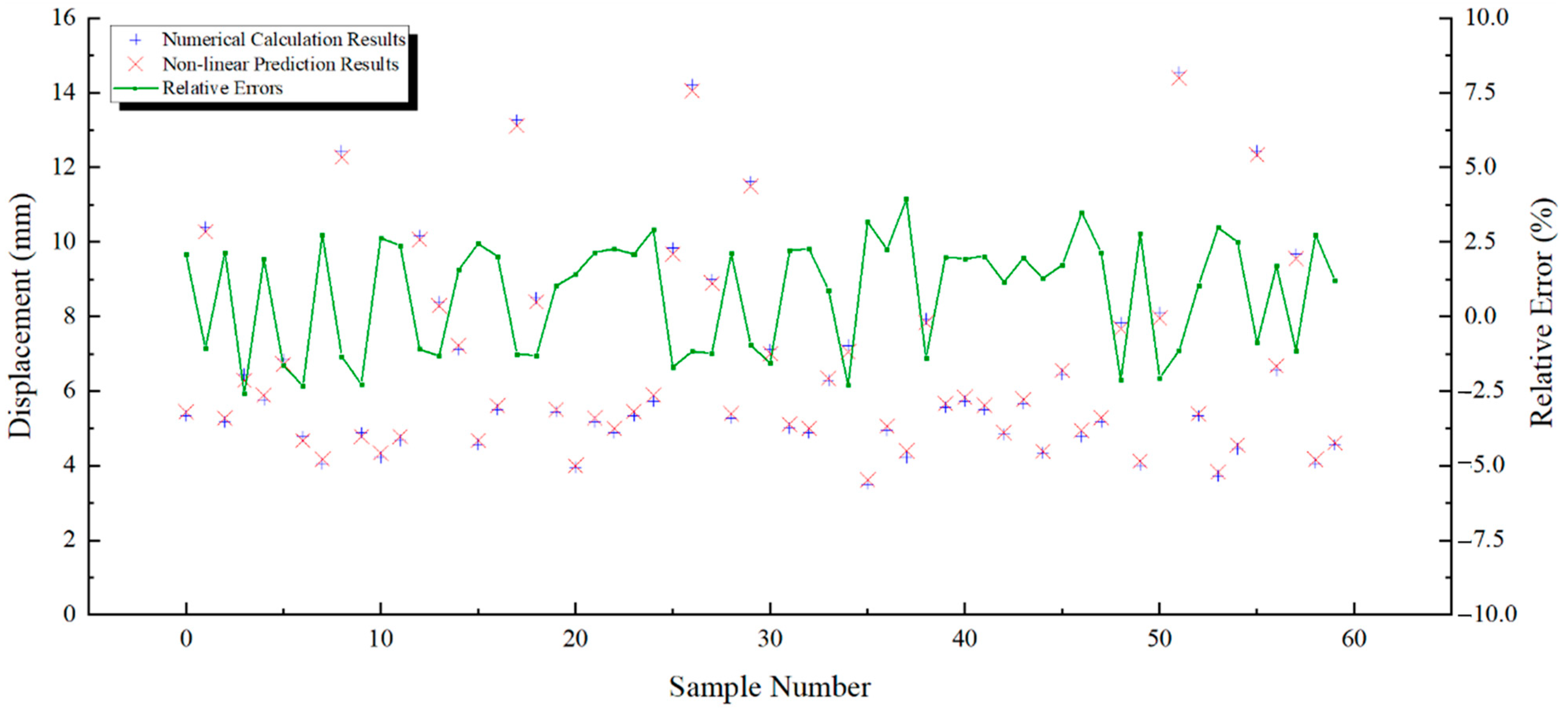
The comparison of the nonlinear mapping results and the numerical simulation of displacements are shown in Figure 3.
The maximum error between the nonlinear mapping results and the numerical simulation results is 3.95%. The comparison results show that the results obtained from the nonlinear mapping relationship used in this paper have less deviation from the numerical orthogonal calculation results and can effectively replace the numerical orthogonal calculation.

4.3. Back Analysis Results

The displacement monitoring values on 6 June 2021 and 7 April 2022 were taken as input data for the back analysis of the rock parameters of the slopes in the first stage of water storage and the second stage of water storage, respectively. The back analysis results of the two water impoundment stages are shown in Table 2 and Table 3.
Comparing the back analysis results of the parameters of the two stages, the back analysis results of the second impoundment stage will be smaller than the back analysis results of the first impoundment stage, which indicates that the elevated reservoir level will lead to the decrease of the mechanical parameters of the slope rock, presumably because the water enters the interior of the slope and thus deteriorates the mechanical parameters of the rock, which in turn leads to the displacement of the slope.

4.4. Back Analysis Results Validation

In order to verify the validity of the back analysis results, this paper uses the parameters obtained from the back analysis for numerical simulation and compares the simulation results with the field monitoring data. The comparison of simulation results and field monitoring data is shown in Table 4 and Table 5.
The absolute errors between the calculated and measured displacements of TPXJ-10 and TPXJ-17 were 0.74 mm and 0.87 mm, respectively. the absolute errors between the calculated and measured displacements of TPXJ-17 and TPXJ-10 were 0.60 mm and 0.59 mm, respectively. the absolute errors of both comparisons were within 1 mm, which indicates that the back analysis method has a high validity.

5. Stability Evaluation of Three-Dimensional Numerical Simulation

5.1. Numerical Model

In order to predict the stability of the third stage of water storage, this study used FLAC3D and the finite difference method [23,24,25] to simulate the safety of the slope under three different conditions.
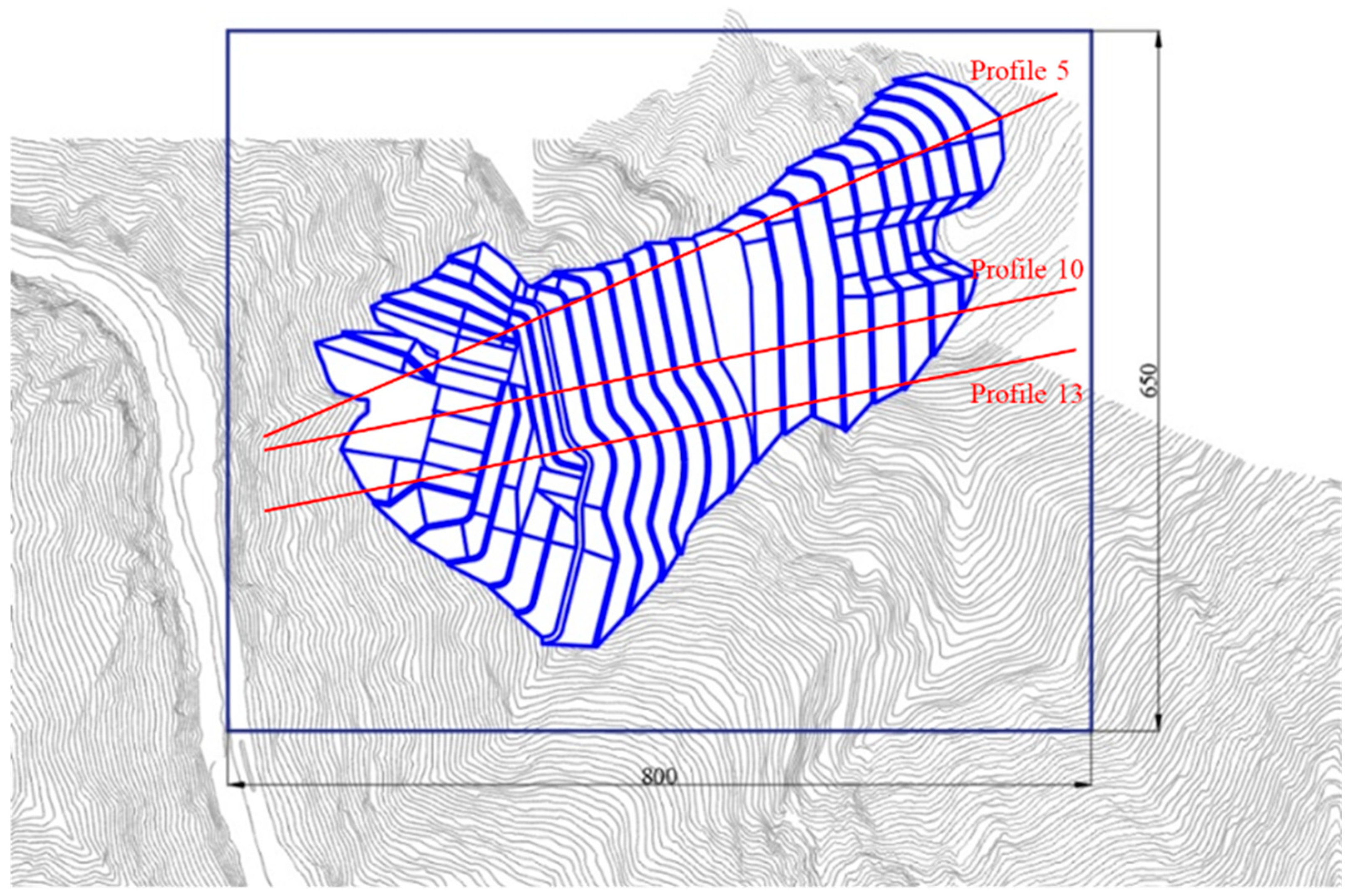
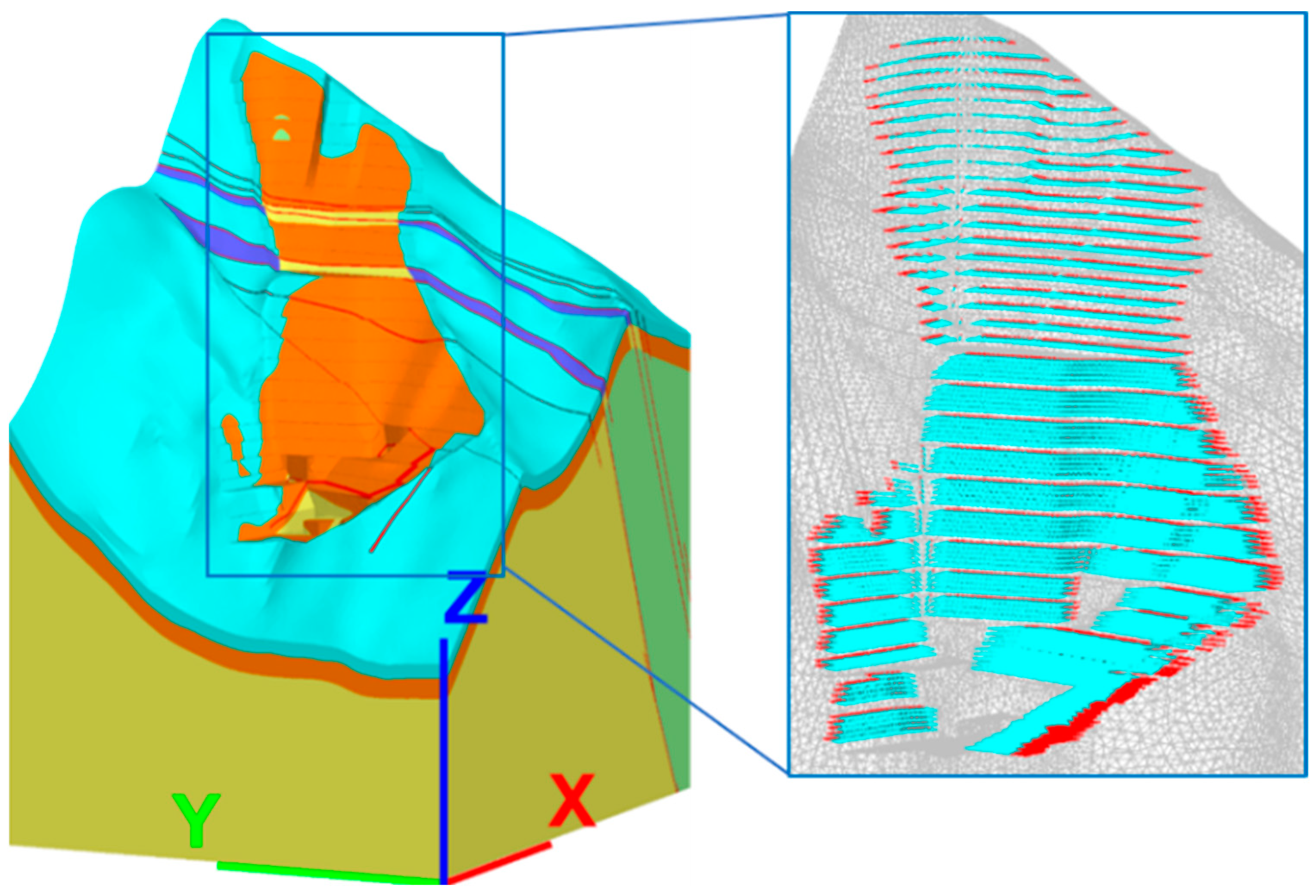
According to the site engineering geological conditions and slope excavation support design scheme, this paper establishes a model of the inlet slope of the flood-discharge structure of Lianghekou Hydropower Project. The elevation of the model bottom is 2300 m, the length is 650 m in the downstream direction, and the width is 800 m in the cross-river direction, as shown in Figure 4. The model and control support arrangement are shown in Figure 5. The model mainly adopts four-node tetrahedral units, and the model contains 3,326,462 elements and 594,993 nodes.
The cables are mainly designed with prestressed cables with 1500 kN and 2000 kN anchor tension and 15° angle of incidence. The lengths of the cables on the slope are different according to the elevation. The modeling is carried out with the cable elements in FLAC3D.

5.2. Simulated Conditions and Parameters

To study the slope stability under different water impoundment conditions, the following conditions are established to analyze the slope changes:
  • Condition I: water level (2785 m) + cable support;
  • Condition II: water level (2815 m) + cable support;
  • Condition III: water level (2845 m) + cable support.
The numerical simulation uses the back analysis results during the second stage of water impoundment as the parameters, as shown in Table 6. The material model used is Mohr Coulomb.

5.3. Numerical Simulation Results Analysis

5.3.1. Numerical simulation Results under Condition I

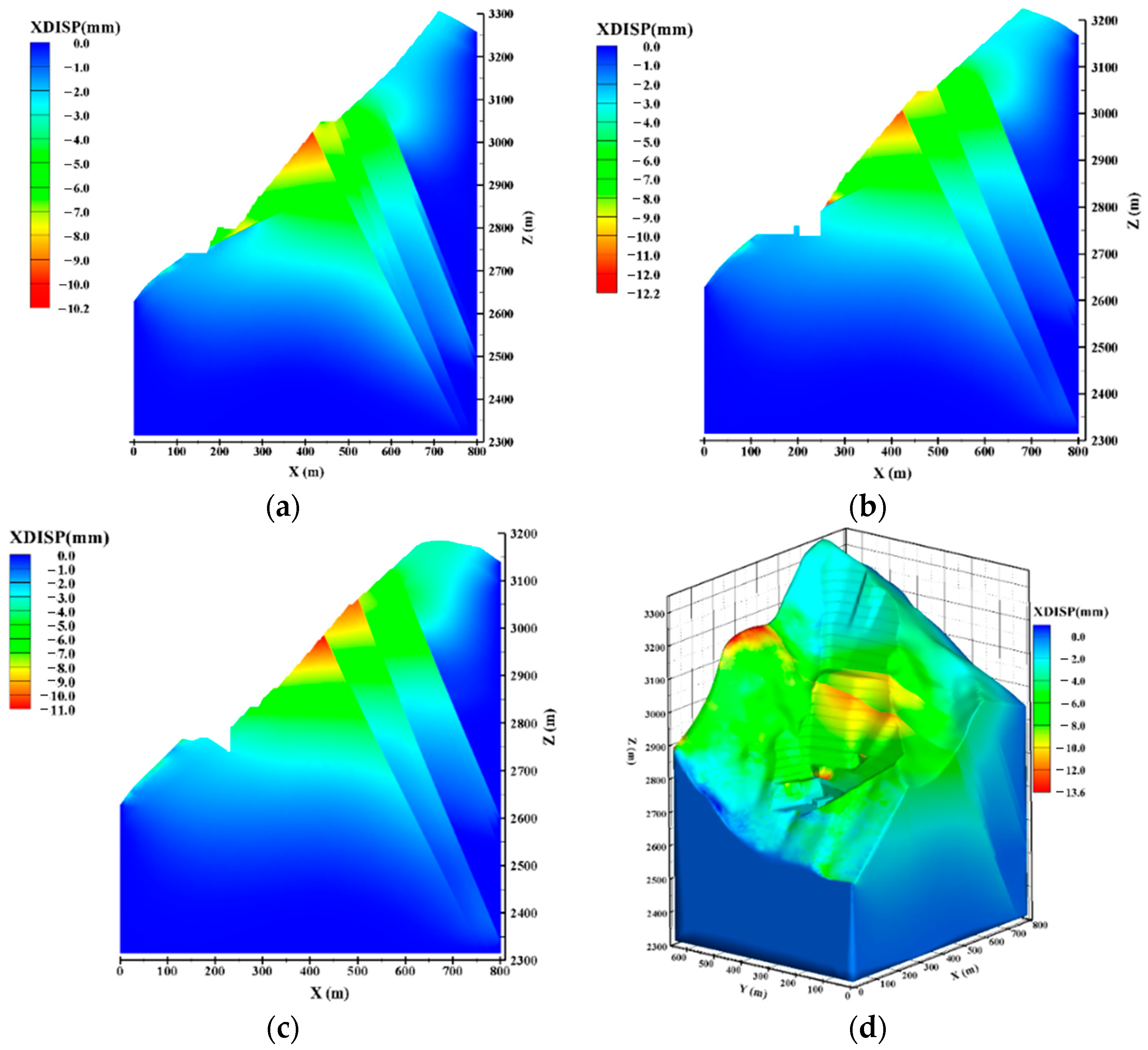
Figure 6 shows the contours of the transverse component of displacement of the slope under condition I. The maximum transverse displacement of the slope is 10.5 mm, which occurs in the middle of the slope. The overall displacement of the slope is mainly in the cross-river direction. Due to the partitioning effect of the fault, the slope displacement shows an obvious stratification phenomenon.
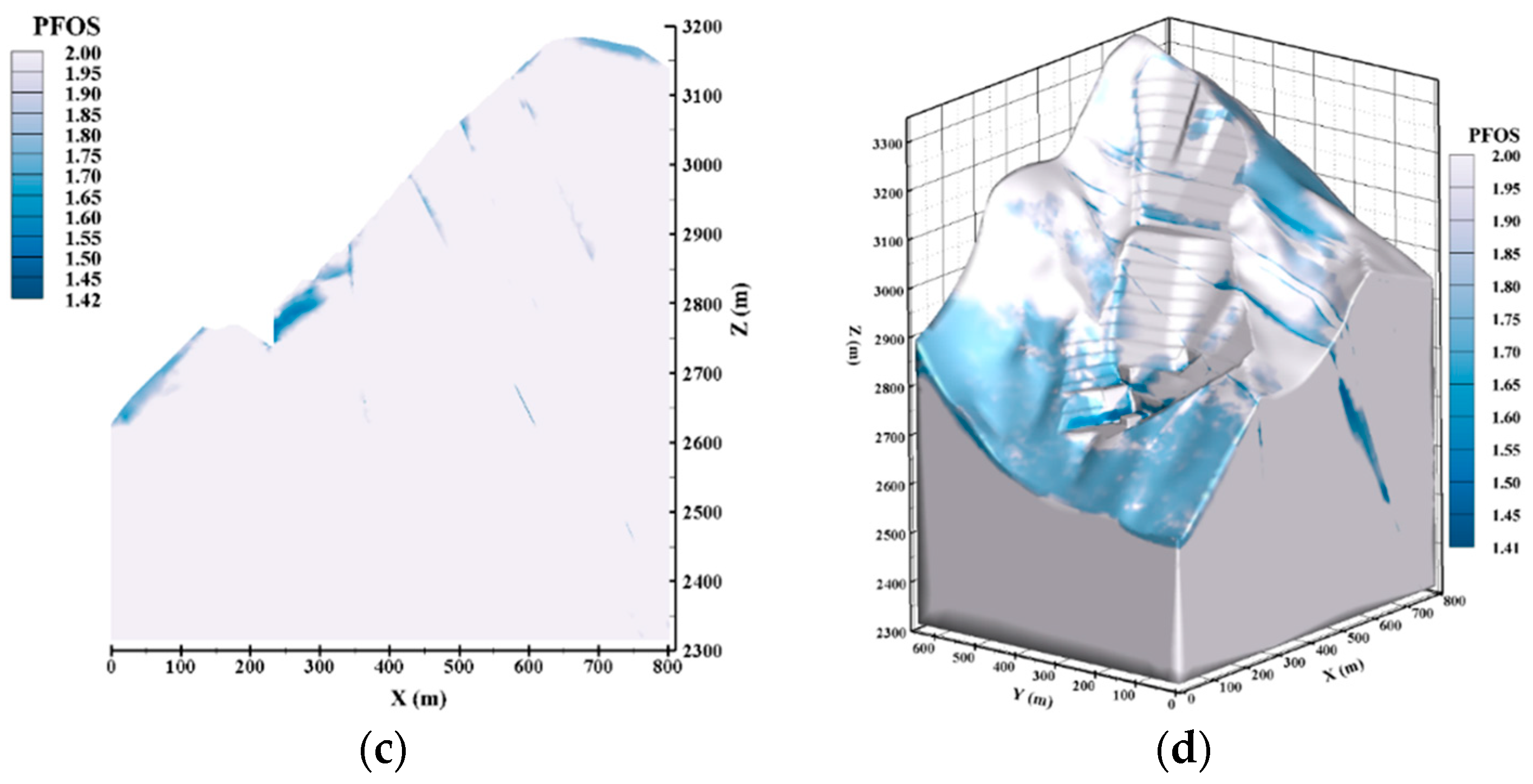
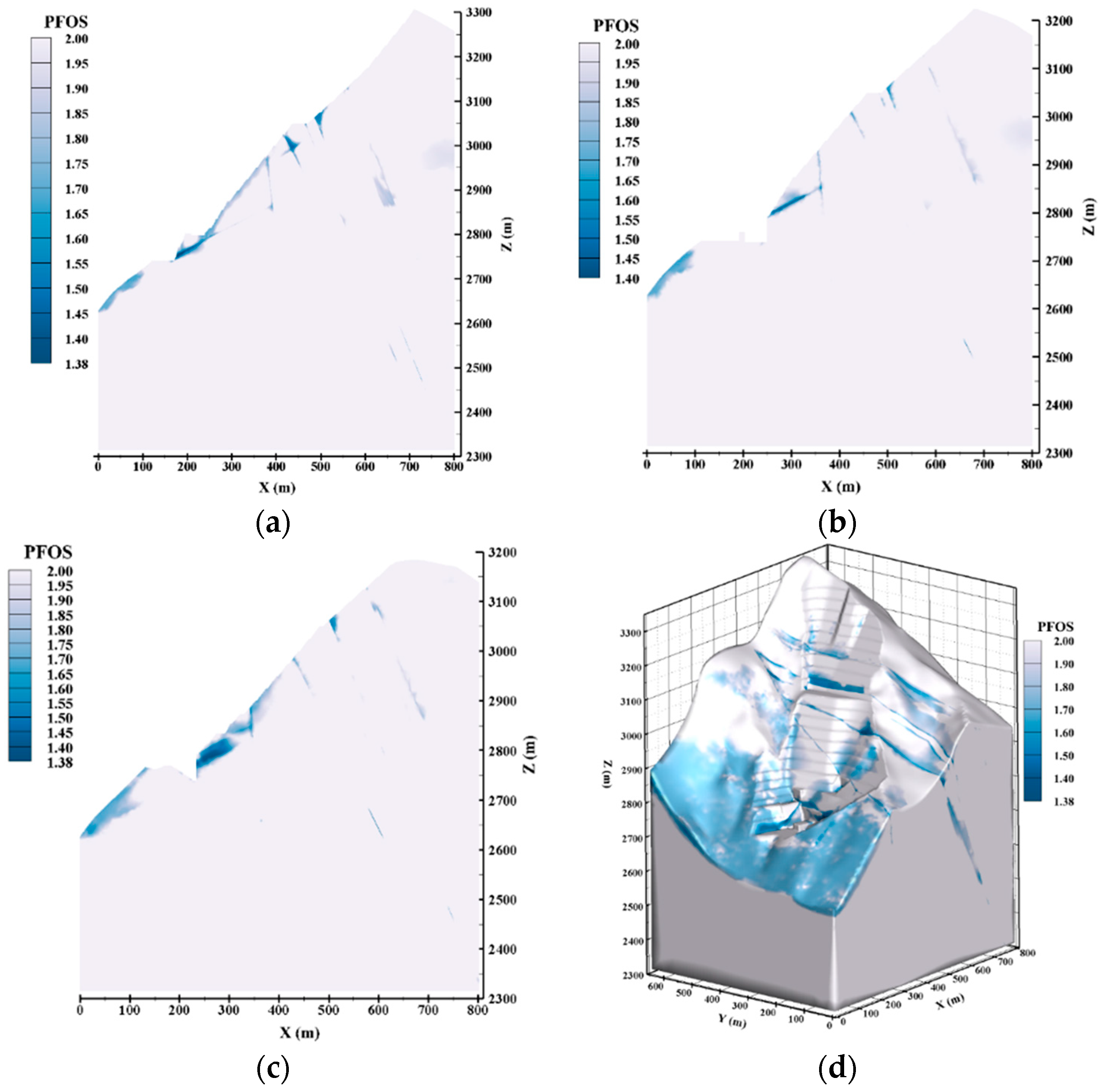
Figure 7 shows the distribution of point factor of safety for the slope under condition I. From the distribution of the point factor of safety, it can be seen that the point factor of safety at the junction of the fault and different rock bodies is smaller, and the point factor of safety inside the rock body is larger. The minimum value of the point factor of safety of the slope is 1.41, which appears at the fault at the front edge of the slope.

5.3.2. Numerical Simulation Results under Condition II

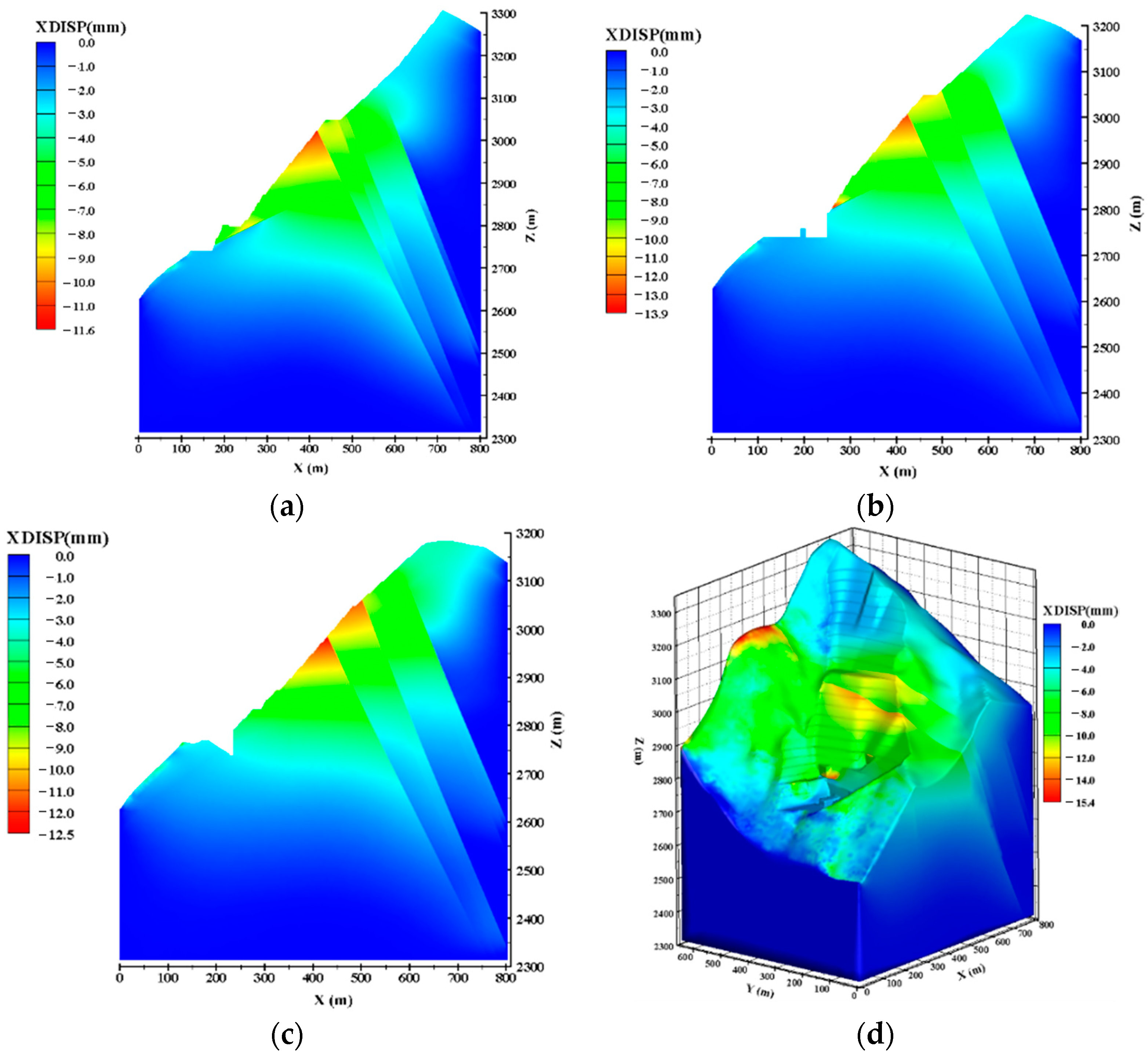
Figure 8 shows the contours of the transverse component of displacement of the slope under condition II. The maximum transverse displacement of the slope is 12.5 mm, which occurs at the front of the slope. As the water level rises to 2815 m, it has already flooded the outcrop of the fb13 fault at the front of the slope, and the weakening of fault parameters caused by water immersion makes the displacement at the front of the slope increase significantly. The danger zone at the front of the slope can be identified from the displacement contour.
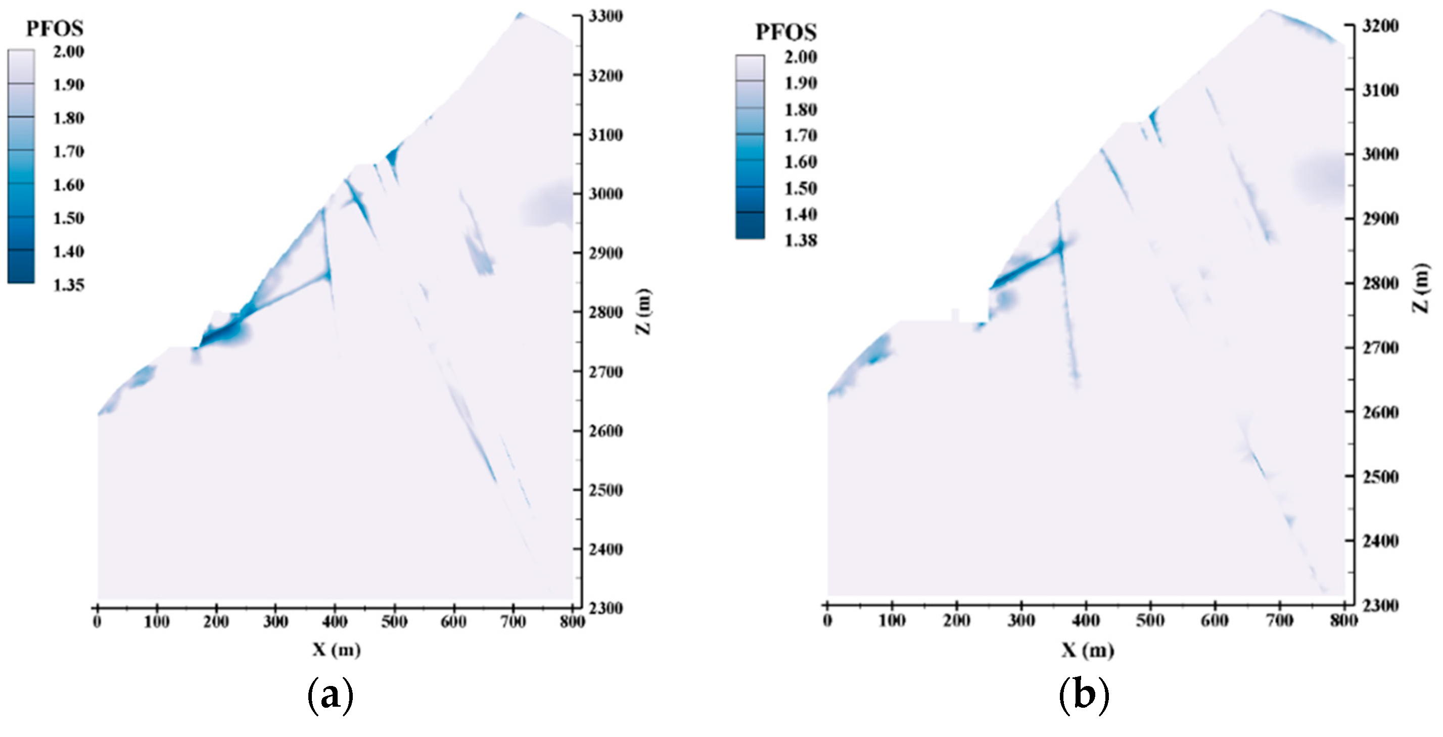
Figure 9 shows the point factor of safety distribution of the slope under condition II. Compared with the point factor of safety distribution in condition I, the minimum value of the point factor of safety of the slope in condition II is 1.38, which appears at the fault. The point factor of safety at the fault at the front edge of the slope decreases significantly.

5.3.3. Numerical Simulation Results under Condition III

Figure 10 shows the contours of the transverse component of displacement of the slope under condition III. The maximum value of the transverse component of displacement is 13.9 mm, which appears at the front of the slope, and the slope shows a similar displacement distribution trend to under condition II. Compared with condition II, the rise of water level leads to further increase in deformation of the front part of the slope in the simulation results under condition III.
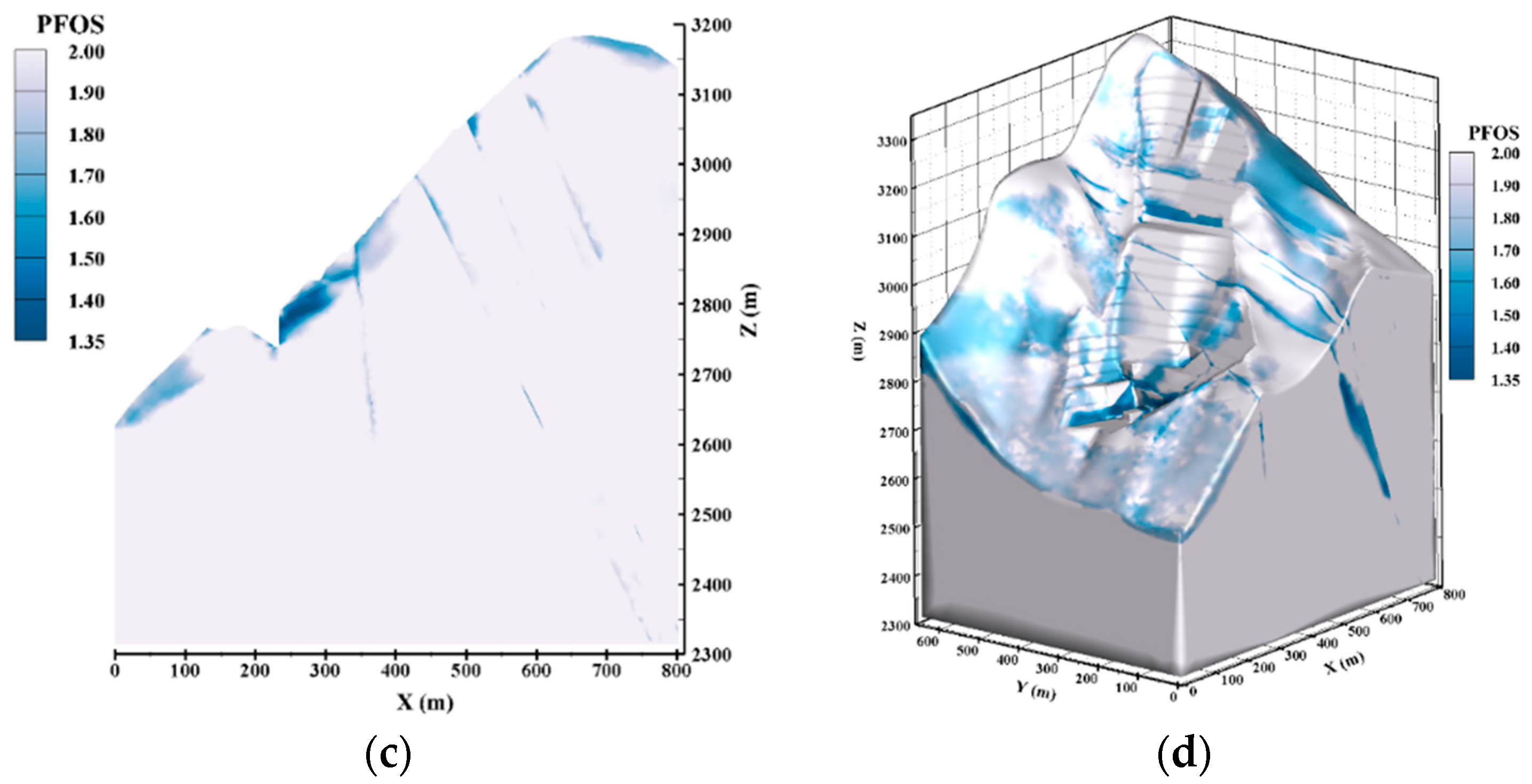
Figure 11 shows the point factor of safety distribution of the slope under condition III. Compared with the distribution of point factor of safety under condition II, the minimum value of point factor of safety of the slope under condition III is 1.35, which appears at the fault. The point factor of safety at the fault of the leading edge of the slope is decreased. The results show that the front edge of the slope is affected by the uplift of reservoir water, which leads to a decrease in safety coefficient and an increase in displacement.

5.4. Safety Evaluation of High Slope

Comparing the changes of displacement under different conditions, it can be seen that the influence of water impoundment in stage III on the front edge of the slope is greater than that on the rear part, the water level rises to 2845 m, and the displacement at the fb13 fault of the front edge increases significantly. Additionally, from the three-dimensional comparison, the impact of water level rise on the middle and rear parts of the slope is smaller than that on the front edge.
Comparing the changes in point factor of safety distribution under different conditions, it can be seen that under condition II, the fb13 fault at the front edge of the slope deteriorates more obviously due to the influence of rising water level. The minimum values of point factor of safety of slope under the three conditions are: 1.41, 1.38, and 1.35, respectively, which all meet the safety requirements.

6. Conclusions and Outlook

6.1. Conclusions

The on-site GNSS monitoring data of the inlet slope of the flood discharge structure of the Lianghekou Hydropower Project were analyzed and studied, and the mechanical parameters of the slope at different water impoundment stages were investigated using GA-LSSVM-BP back analysis. The deformation and point factor of safety under different reservoir water level conditions were also studied using numerical simulation analysis. The following conclusions are obtained:
(1)
After the second stage of water impoundment, the maximum value of slope deformation monitoring data is 20.6 mm, and the deformation is still in a controllable state. After the second stage of water impoundment, the slope deformation demonstrates an obvious hysteresis phenomenon.
(2)
The GA-LSSVM-BP model is used to back analyze the mechanical parameters of the slope in the two water impoundment stages, and the back analysis results show that the mechanical parameters of the slope will be significantly weakened by the effect of seepage.
(3)
Three-dimensional numerical simulation analysis of the slope under different conditions shows that the stability of the slope decreases as the reservoir water level rises, but the minimum values of point factor of safety of slope under the three conditions are: 1.41, 1.38, and 1.35, respectively, which all meet the safety requirements. Slope stability is mainly limited by the fb13 fault at the front of the slope. The obvious danger area formed by the cutting of the fb13 fault appears in the numerical simulation results, and this area needs to be focused on.

6.2. Outlook

This study mainly focuses on the stability of the inlet slope of the flood discharge building of the Lianghekou Hydropower Project during the water impoundment stage. For the slope stability during the subsequent dispatching of the reservoir, it is also necessary to study the slope stability under various dispatching conditions after obtaining the relevant information in the future. After obtaining the data from field monitoring, the back analysis model can be used to analyze the mechanical parameters of slopes, which can be supplemented with experimental research to further study the weakening of parameters under the conditions of water level change. Additionally, some numerical simulation studies can be carried out to analyze the stability changes of slope under impoundment or discharge.

Author Contributions

Conceptualization, X.X., W.X., and G.Z.; methodology, X.X. and W.H.; software, X.X. and W.H.; validation, S.C. and L.Y.; formal analysis, X.X.; data curation, X.X.; writing—original draft preparation, X.X.; writing—review and editing, W.X. and G.Z.; project administration, W.X. All authors have read and agreed to the published version of the manuscript.

Funding

This research was funded by the National Natural Science Foundation of China (grant number: 51939004; 52109122).

Institutional Review Board Statement

Not applicable.

Informed Consent Statement

Not applicable.

Data Availability Statement

The original contributions presented in the study are included in the article. Further inquiries can be directed to the corresponding author.

Acknowledgments

The authors would like to thank Yalong River Hydropower Development Company, Ltd. for providing relevant field monitoring data for the study.

Conflicts of Interest

The authors declare no conflict of interest.

References

  1. Vásárhelyi, B.; Ván, P. Influence of water content on the strength of rock. Eng. Geol. 2006, 84, 70–74. [Google Scholar] [CrossRef]
  2. Yan, L.; Xu, W.; Li, B.; Ji, H.; Gu, J. Evaluation of Deformation and Permeability Behavior of Amygdaloidal Basalt under a Triaxial Cyclic Loading Creep Test. Geofluids 2020, 2020, 6673530. [Google Scholar] [CrossRef]
  3. Shi, X.C.; Cai, W.Q.; Meng, Y.F.; Li, G.; Wen, K.; Zhang, Y.R. Weakening laws of rock uniaxial compressive strength with consideration of water content and rock porosity. Arab. J. Geosci. 2016, 9, 369. [Google Scholar] [CrossRef]
  4. Zhu, J.; Deng, J.H.; Chen, F.; Ma, Y.J.; Yao, Y.F. Water-Weakening Effects on the Strength of Hard Rocks at Different Loading Rates: An Experimental Study. Rock Mech. Rock Eng. 2021, 54, 4347–4353. [Google Scholar] [CrossRef]
  5. Cheng, Z.; Wang, H.; Xu, W.; Yan, L. Numerical investigation of the flow characteristics and permeability of 2D irregular columnar jointed rock masses. Eng. Comput. 2021, 38, 4091–4110. [Google Scholar] [CrossRef]
  6. Masuda, K. Effects of water on rock strength in a brittle regime. J. Struct. Geol. 2001, 23, 1653–1657. [Google Scholar] [CrossRef]
  7. Pan, Y.; Wu, G.; Zhao, Z.; He, L. Analysis of rock slope stability under rainfall conditions considering the water-induced weakening of rock. Comput. Geotech. 2020, 128, 103806. [Google Scholar] [CrossRef]
  8. Malkowski, P.; Ostrowski, L.; Bozecki, P. The impact of the mineral composition of Carboniferous claystones on the water-induced changes of their geomechanical properties. Geol. Geophys. Environ. 2017, 43, 43–55. [Google Scholar] [CrossRef] [Green Version]
  9. Zhou, Z.L.; Cai, X.; Cao, W.Z.; Li, X.B.; Xiong, C. Influence of Water Content on Mechanical Properties of Rock in Both Saturation and Drying Processes. Rock Mech. Rock Eng. 2016, 49, 3009–3025. [Google Scholar] [CrossRef]
  10. Li, T.T.; Wang, C.Y. Numerical Simulation Study on Formation and Evolution Process of Water-Inrush Channel in Floor Under High Water Pressure. Geotech. Geol. Eng. 2019, 37, 3007–3012. [Google Scholar] [CrossRef]
  11. Saada, Z.; Maghous, S.; Garnier, D. Stability analysis of rock slopes subjected to seepage forces using the modified Hoek–Brown criterion. Int. J. Rock Mech. Min. Sci. 2012, 55, 45–54. [Google Scholar] [CrossRef]
  12. Meng, Y.; Weiya, X.U.; Liu, Z.; Liu, D.; Cai, D. Analysis of 3D visualization of safety monitoring for complicated high rock slope engineering. Chin. J. Rock Mech. Eng. 2010, 29, 2500–2509. [Google Scholar]
  13. Mukhlisin, M.; Naam, S.I. Effect of rock fragments on pore water pressure and slope stability at a hillslope. J. Geol. Soc. India 2015, 86, 337–343. [Google Scholar] [CrossRef]
  14. Yeh, P.-T.; Lee, K.Z.-Z.; Chang, K.-T. 3D Effects of permeability and strength anisotropy on the stability of weakly cemented rock slopes subjected to rainfall infiltration. Eng. Geol. 2020, 266, 105459. [Google Scholar] [CrossRef]
  15. Xu, W.; Song, X.; Zhou, W. Numerical analysis on deformation and stress of high slope of intake and interaction of dam-slope and tunnel at huge hydropower project. Chin. J. Rock Mech. Eng. 2004, 23, 2712–2717. [Google Scholar]
  16. Huanling, W.; Weiya, X.U.; Tong, F. Coupled analysis of fracture rock mass slope saturated-unsaturated seepage field and stress field in flood discharge atomized rain area. Rock Soil Mech. 2008, 29, 2397–2403. [Google Scholar]
  17. Kafle, L.; Xu, W.-J.; Zeng, S.-Y.; Nagel, T. A numerical investigation of slope stability influenced by the combined effects of reservoir water level fluctuations and precipitation: A case study of the Bianjiazhai landslide in China. Eng. Geol. 2022, 297, 106508. [Google Scholar] [CrossRef]
  18. Xue, X.; Li, K.; Huang, Q.; Xu, B. Deformation Characteristics of Reservoir Slopes in the Initial Impoundment Period. Mt. Res. 2016, 34, 323–330. [Google Scholar]
  19. Holland, J.H. Adaptation In Natural And Artificial Systems: An Introductory Analysis with Applications to Biology, Control, and Artificial intelligenc; University of Michigan Press: Ann Arbor, MI, USA, 1975. [Google Scholar]
  20. Cortes, C.; Cortes, C.; Vapnik, V.; Llorens, C.; Vapnik, V.N.; Cortes, C.; Côrtes, M. Support-vector networks. Mach. Learn. 1995, 20, 273–297. [Google Scholar] [CrossRef]
  21. Suykens, J.; Lukas, L.; Van, P.; De, D.B.; Vandewalle, M.J. Least Squares Support Vector Machine Classifiers: A Large Scale Algorithm; Katholieke Universiteit Leuven: Leuven, Belgium, 2000. [Google Scholar]
  22. Cai, Z.; Xu, W.; Meng, Y.; Chong, S.; Wang, R. Prediction of landslide displacement based on GA-LSSVM with multiple factors. Bull. Eng. Geol. Environ. 2015, 75, 637–646. [Google Scholar] [CrossRef]
  23. Rutqvist, J.; Wu, Y.-S.; Tsang, C.-F.; Bodvarsson, G. A modeling approach for analysis of coupled multiphase fluid flow, heat transfer, and deformation in fractured porous rock. Int. J. Rock Mech. Min. Sci. 2002, 39, 429–442. [Google Scholar] [CrossRef]
  24. Lin, H.; Cao, P.; Li, J.; Jiang, X.; He, Z. Deformation stability of three-dimensional slope based on Hoek-Brown criterion. Rock Soil Mech. 2010, 31, 3656–3660. [Google Scholar]
  25. Lu, H.; Yao, D.; Hu, Y.; Guo, P. Analysis of failure characteristics and stability of layered rock slope based on multi-fracture model of FLAC3D. Adv. Sci. Technol. Water Resour. 2017, 37, 36–41. [Google Scholar]
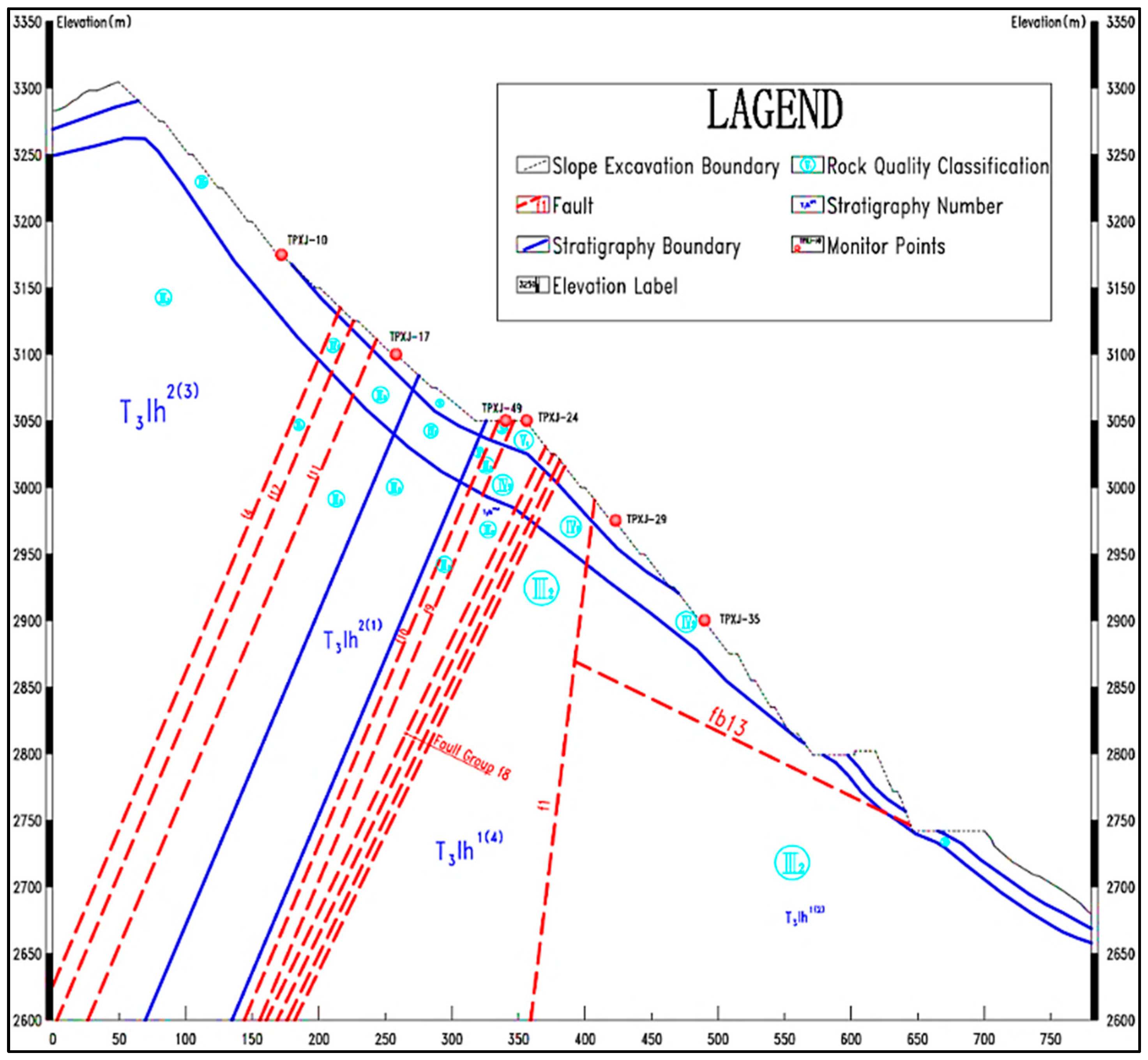
Figure 1. Typical profile of the inlet slope of the flood-discharge structure.
Applsci 13 01729 g001
Figure 2. GNSS monitoring series data of high slope.
Applsci 13 01729 g002
Figure 3. Comparison of nonlinear results and simulation results of displacements.
Applsci 13 01729 g003
Figure 4. Modeling range and typical profile location.
Applsci 13 01729 g004
Figure 5. Numerical model and control support arrangement.
Applsci 13 01729 g005
Figure 6. Transverse riverward displacement distribution of slope under condition I. (a) Profile 5; (b) profile 10; (c) profile 13; (d) entire body.
Applsci 13 01729 g006
Figure 7. Point factor of safety distribution of slope under condition I. (a) Profile 5; (b) profile 10; (c) profile 13; (d) entire body.
Applsci 13 01729 g007aApplsci 13 01729 g007b
Figure 8. Transverse riverward displacement distribution under condition II. (a) profile 5; (b) profile 10; (c) profile 13; (d) entire body.
Applsci 13 01729 g008
Figure 9. Point factor of safety distribution of slope under condition II. (a) Profile 5; (b) profile 10; (c) profile 13; (d) entire body.
Applsci 13 01729 g009
Figure 10. Transverse riverward displacement distribution under condition III. (a) Profile 5; (b) profile 10; (c) profile 13; (d) entire body.
Applsci 13 01729 g010
Figure 11. Point factor of safety distribution of slope under condition III. (a) Profile 5; (b) profile 10; (c) profile 13; (d) entire body.
Applsci 13 01729 g011aApplsci 13 01729 g011b
Table 1. Reference intervals for back analysis of mechanical parameters.
Rock GroupsDeformation Modulus (GPa)Poisson’s RatioCohesion (MPa)Internal Friction Angle (°)
ClassSubclass
IIIIII111.0~13.00.22~0.281.4~1.648.2~52.2
III26.3~9.80.26~0.321.1~1.340.4~45.4
IVIV14.5~7.50.28~0.340.8~1.038.4~42.4
IV24.1~5.90.30~0.360.4~0.832.9~40.9
VV11.6~3.40.29~0.390.1~0.723.0~39.0
Table 2. Back analysis results of rock parameters for stage I of water impoundment.
Rock GroupsDeformation Modulus (GPa)Poisson’s RatioCohesion (MPa)Internal Friction Angle (°)
ClassSubclass
IIIIII112.000.251.5050.3
III26.510.290.8240.4
IVIV14.980.310.5836.5
IV22.480.340.4731.0
VV11.760.350.1928.6
Table 3. Back analysis results of rock parameters for stage II of water impoundment.
Rock GroupsDeformation Modulus (GPa)Poisson’s RatioCohesion (MPa)Internal Friction Angle (°)
ClassSubclass
IIIIII112.000.251.4749.5
III26.420.290.7640.0
IVIV14.980.310.5736.2
IV22.250.340.4131.0
VV11.720.370.1927.8
Table 4. Comparison of simulation results and field monitoring data for stage I of water impoundment.
Monitoring NumberMonitoring Values (mm)Simulation Values (mm)Absolute Error (mm)Relative Error (%)
TPXJ-108.798.050.749.19
TPXJ-175.996.860.8714.50
Table 5. Comparison of simulation results and field monitoring data for stage II of water impoundment.
Monitoring NumberMonitoring
Values (mm)
Simulation
Values (mm)
Absolute Error (mm)Relative Error (%)
TPXJ-108.619.210.606.97
TPXJ-179.819.220.596.01
Table 6. Rock parameters used for numerical simulation.
Rock GroupsDensity (kg/m3)Deformation Modulus (GPa)Poisson’s RatioCohesion (MPa)Internal Friction Angle (°)
ClassSubclass
IIIIII1275012.000.251.4749.5
III227506.420.290.7640.0
IVIV127004.980.310.5736.2
IV226002.250.340.4131.0
VV26001.720.370.1927.8
Disclaimer/Publisher’s Note: The statements, opinions and data contained in all publications are solely those of the individual author(s) and contributor(s) and not of MDPI and/or the editor(s). MDPI and/or the editor(s) disclaim responsibility for any injury to people or property resulting from any ideas, methods, instructions or products referred to in the content.