Article

Evaluation and Characterization of the Influence of Solar Position Algorithm on the Performance of Parabolic Trough Solar System

1
Department of Environmental Science and Engineering, University of Science and Technology of China, 96 Jinzhai Road, Hefei 230026, China
2
Asset Management Co., University of Science and Technology of China, 96 Jinzhai Road, Hefei 230026, China
*
Author to whom correspondence should be addressed.
Appl. Sci. 2023, 13(3), 1821; https://doi.org/10.3390/app13031821
Submission received: 5 January 2023 / Revised: 25 January 2023 / Accepted: 27 January 2023 / Published: 31 January 2023
(This article belongs to the Section Energy Science and Technology)

Abstract

:
For the open loop control system based on the solar position algorithm (SPA), without sensor correction, the error of SPA will bring the tracking error directly to decrease the efficiency of the solar system. By comparing with SPA proposed by NREL, this paper first evaluates main SPAs with different accuracy and presents the error of SPA on tracking error. Based on the annual average efficiency of the solar trough system, this paper evaluates the impact of the tracking error caused by SPA on the solar trough system, and proposes that the average SPA calculation error can be applied to characterize the impact of SPA on the trough solar system. By making a comparison of solar trough system efficiency calculated with fixed annual average tracking error and normal constantly changing tracking error within a year, respectively, the evaluation results show that for most SPAs, the introduced error is less than 0.05%, and only a few empirical algorithms with large tracking errors introduce larger errors, but they are not suitable for the trough solar system. Therefore, the SPA evaluation method proposed in this paper is applicable to the solar trough system.

1. Introduction

Over past decade, concentrating solar power technology (CSP) has presented great advances, and the linear focus parabolic trough solar system is one of the most widespread and mature solar power technologies [1]. It mainly consists of a parabolic trough reflecting mirror, tracking system and vacuum pipe receiver. The tracking system plays an important role in the operation of the parabolic solar collector which could drive the collector to track the sun, so that the reflector can focus solar rays projected on the mirror onto the receiver, which can convert the collected solar energy into heat energy and transfer it to the heat-transfer medium.
The CSP technologies require high-accuracy solar tracking systems in order to achieve better performance. The algorithms used in the active solar system could be classified according to the solar tracking control strategies: open-loop, closed-loop and hybrid-loop. The open-loop strategy has no control feedback from a solar sensor, based on solar coordinates calculated from SPA to estimate the sun’s apparent position with respect to a geographical location on Earth. The closed-loop strategy has control feedback from a solar sensor and can achieve high solar tracking accuracy without an SPA [2].
For the open-loop strategy, in order to compute the sun’s position, SPA need to input parameters such as the geographic location and time. The sun’s apparent position generated by the SPA represent the set point of the control algorithm, which will finally be transformed into angular position for the actuators of the active solar tracking system in the control unit. In order to keep down the price of the tracking system, the calculation of sun position and control other tracking system functions in controller is based on a low-cost microprocessor. This imposes significant restrictions on the SPA to be used in the tracking system [3].
The solar trackers can be classified as single-axis tracking (SAT) mechanism and double-axis tracking (DAT) mechanism [4,5]. DAT mechanism requires the direction of incident solar ray and optical axis to be consistent. The single-axis tracking (SAT) mechanism requires the incidence ray to be located in the plane containing the main optical axis and focal line. SAT tracking method can be further sub-divided according to its focal line, such as EW axis system tracking from south to north and NS axis system tracking from east to west. In addition, the spin axis of the polar axis tracking system points directly to the North Pole and tracks from east to west. Therefore, there are four common tracking methods for parabolic trough solar system: (1) north–south axis tracking method; (2) east–west axis tracking method; (3) polar axis tracking method; (4) two-axis tracking method [6]. For the SAT system, there is an included angle between the incident ray and the optical axis, which reduces the intensity of the incident sunlight. Among the four tracking methods, the DAT system has the best performance. It has two rotating axes which are perpendicular to each other, and the reflector rotates around the two axes at the same time so that the optical axis of the mirror is consistent with the direction of solar rays [6]. However, the complexity of DAT system is higher and it has greater manufacturing and maintenance costs than the one-axis tracking system.
There are several algorithms for computing the sun position with different levels of accuracy and complexity which have been published for solar radiation applications. These calculation methods can be classified into two groups. The first group is relatively simple methods with low accuracy that uses empirical formulae to directly calculate equations of time and solar declination. The second consists of more complex algorithms considering nutation, aberration and other factors. For relatively simple algorithms, basic solar parameters such as solar declination and equation of time can be calculated using the time of year. Among those algorithms, the method proposed by Spencer in 1971 is the most widely cited in the solar literature, with a maximum error of 0.28° [7]. The second consists of more complex algorithms, considering nutation and other effects, and requires the time and geographical location of the observer to calculate the ecliptic coordinates, celestial coordinates and local horizontal coordinates of the sun. These algorithms usually have high accuracy, but can generally only be used within a certain time range. The PSA algorithm proposed by Blanco et al. is limited to the period from 1999 to 2015 with uncertainty of 0.01 degree. It has been revisited to improve its accuracy in the period from 2020 to 2050 and achieves a 25% decrease in the average error of the angular deviation with respect to the true solar vector [3,8]. Grena proposed five algorithms with maximum errors in the solar position spanning from 0.19 to 0.0027 degree, and is limited in the period from 2010 to 2110 [9]. The ideal SPA is supposed to be both accurate and efficient at the same time. However, those SPAs with low uncertainties always require a lot of complex corrections, which increase their computation cost. NREL have proposed a SPA in the period from the year −2000 to 6000 with uncertainties of ±0.0003° [10]. Compared with other methods, its errors can be neglected, which can be regarded as an accurate algorithm. In this paper, we assume that the solar position calculated by SPA of NREL is the real solar position. The calculation error of other algorithms is obtained by comparing with the NREL algorithm.
The error generated by SPA changes greatly with the change of the solar position in one year. For annual performance of solar trough system, accurate calculation needs to firstly calculate the solar position error from error of SPA at every moment, and then calculate the impact of these errors on the optical effect of the system. Whether using a calculation method or measurement method, it requires lengthy calculation and measurement. In order to evaluate the impact of SPA calculation error more simply, we try to use average tracking error to represent constantly changing tracking error. However, the relation between efficiency and tracking error is not linearity. When evaluating the impact of tracking error over a period of time, using the average tracking error to represent the changing error will lead to error.
The main aim of this study is to evaluate the error when average tracking error generated from SPA error is applied to characterize its impact on trough solar system. In this paper, the numerical simulation experiment is used to check and estimate the error of this method. The error influence of SPA on the performance of parabolic trough solar system is also evaluated.

2. Calculation Methods

The research object of this paper is the trough solar system with a closed-loop tracking strategy. It mainly studies the influence of the solar position algorithm on the system performance. This paper assumes that the tracking error is mainly from SPA calculation error. We use the average error of SPA as the tracking error to calculate the optical efficiency of the parabolic trough system. At same time, SPA error at every moment is applied to calculate the optical efficiency of the system. We apply the efficiency using SPA error at every moment as a standard to evaluate the error of the optical efficiency of parabolic trough solar system under different calculation methods.

2.1. Optical Efficiency of Solar Trough System

Applying the calculation method of trough solar system we developed before [11], the effective solar radiation on the mirror is represented by B e f f ( θ ) , the solar radiation at one reflection point P is B e f f ( θ ) . ρ , α , τ is reflectivity of mirror, transmittance of glass envelope and absorptivity of vacuum receiver, respectively, ρ τ α B e f f ( θ ) d θ refers to the amount of solar radiation reflected on the receiver and absorbed by the reflection point P. In addition, when the incident light is not perpendicular to the reflector, a part of the solar rays may not reach the receiver after reflection. The impact of this part on the efficiency is called end loss. The optical efficiency of reflection point P is:
η P ( y )   =   θ 0 θ 0 ρ τ α B e f f ( θ d θ ) I i n     ( 1     f 0 tan ( θ )     ( 1   +   tan 2 ( β / 2 ) ) L )
The later part of the function is end loss. L is the length of parabolic mirror, f 0 is the focal length, β is the rim angle of the point P, I i n is the incidence solar energy flux which equals to D N I i n     cos ( θ ) , θ 0 is maximum angle of solar rays to the receiver.
Then, the average optical efficiency of the whole system is calculated from the integration of each point of mirror as following:
η 0   =   R W η P ( y ) I i n d y   +   0 r 0 t a I i n cos ( φ ) d y I i n     W   =   0 r 0 η P ( y )   +   0 r 0 t a cos ( δ ) d y W
The former part of the equation is the contribution of the reflected rays, and the later part of the equation is the contribution of the rays irradiated on the collector directly. R is the radius of vacuum tube receiver, W is the width of the parabolic trough mirror, δ is the incidence angle of the radiation on the absorption tube which can be calculated from the geometry.
This method also takes the influence of incidence angle of solar rays on the efficiency of trough solar system into consideration [11].
q n e t ( t ) is the net energy power in any time which is calculated in following way:
q n e t ( t )   =   I i n ( t ) cos ( θ )     η 0     q l o s s ( t )
The energy loss q l o s s is calculated as follows:
q l o s s   =   a 0   +   a 1 T   +   a 2 T 2   +   a 3 T 3   +   D N I     ( b 0   +   b 1 T 2 )

2.2. Tracking Error

In this paper, we assume that tracking errors result from errors of SPA entirely and calculate the tracking error of trough solar system by comparing with NREL’s SPA. For a system with different tracking methods, the tracking angle and incidence angle can be calculated as follows [6]:
For north–south axis tracking mode, the tracking angle θ T r a c k i n g   =   a r c t a n ( sin γ / tan z ) , which γ is solar azimuth; For east–west axis tracking mode, the tracking angle θ T r a c k i n g   =   a r c t a n ( cos γ / tan z ) , which z is solar zenith; For polar axis tracking mode, the tracking angle is equal to the hour angle ω .
In the past, when calculating the influence of tracking error on the performance of the trough solar system, we intended to add it to the total optical error. The calculation formula is:
σ o p t i c a l 2   =   4 σ c o n t o u r 2   +   σ s p e c u l a r 2   +   λ ( 4 σ c o n t o u r 2   +   σ s p e c u l a r 2 )   +   σ d i s p l a c e m e n t 2   +   σ t r a c k i n g 2
When the tracking error is much smaller than the optical error, the error of this formula is small. However, while the tracking error is larger, especially larger than the optical error, the calculation error is also larger. Some simplified SPAs take fewer factors into consideration, having simple formulae and low accuracy. These methods will introduce larger tracking errors. When the tracking error σ t r a c k i n g is considered, the ray from sun center is reflected σ t r a c k i n g away from the ray to the focus point, then the up and low limit of integration in Formula (1) is from ( θ 0   +   σ t r a c k i n g ) to ( θ 0     σ t r a c k i n g ) [12].

2.3. Solar Position Algorithms

The complexity of the algorithms is an especially significant issue since the operations required by the algorithms must be performed by control systems. A reduced complexity allows the algorithms to be employed on simple and low-cost control systems. The complexity of an algorithm could be measured by counting the required number of products and divisions, and ignoring sums and subtractions (considered as negligible with respect to multiplications and divisions). Grena has tested the calculation time, completed on a Sony Vaio laptop equipped with an Intel Core-Duo P8700 processor with 2.53 GHz clock, using the GNU C++compiler. He find out that sums and products are almost indistinguishable from the point of view of computational time; divisions and square roots are roughly 10 times slower; trigonometric functions, direct and inverse, have a computational time among 25 and 50 times a sum [9].
We can find several SPAs with different levels of accuracy and complexity in the solar engineering literature. This paper evaluates several SPA algorithms. Among them, the SPA proposed by NREL is the one with the highest accuracy. Its accuracy is about two orders of magnitude lower than other algorithms, but its computation cost is also very high, more than 10,000. In this paper, we assume that the sun position calculated by SPA proposed by NREL is the real sun position, which is used to evaluate the error of the result calculated by other algorithms.
Generally, SPA requires time and geographical location to calculate sun position. The simplest method is to first calculate the solar declination and hour angle by the empirical formula, and then calculate the sun’s azimuth angle and altitude angle through the following formula:
sin z   =   sin l sin δ   +   cos l cos δ cos ω
γ   =   A r c t a n 2 ( sin ω cos ω sin l     tan δ cos l )
where δ is solar declination angle, ω is hour angle, l is latitude.

3. Model Validation

We develop a calculation method and program to calculate the efficiency of parabolic trough system and use it to evaluate the effect of tracking error on the performance of system. The method in this paper is an improvement of the previous program, which has been verified by experiments. However, the algorithms of the influence of tracking error on performance added in this paper lack experimental data for verification. In this paper, we mainly use the SolTrace program to evaluate. Since the intercept factor is one of the key result of our model, we calculate the intercept factor of trough system under different tracking error by SolTrace, and draw a comparison with the result developed by our program. We use the same parameters of trough system in SolTrace, take the sun shape profile as 4.65 mrad, the optical error in both x and y direction is 6 mrad, and set the sun shape as Gaussian distribution. We also compute the optical efficiency of solar system and make a comparison with result developed by SolTrace. To simplify the model, we assume the incidence angle is 0, regardless of energy loss.
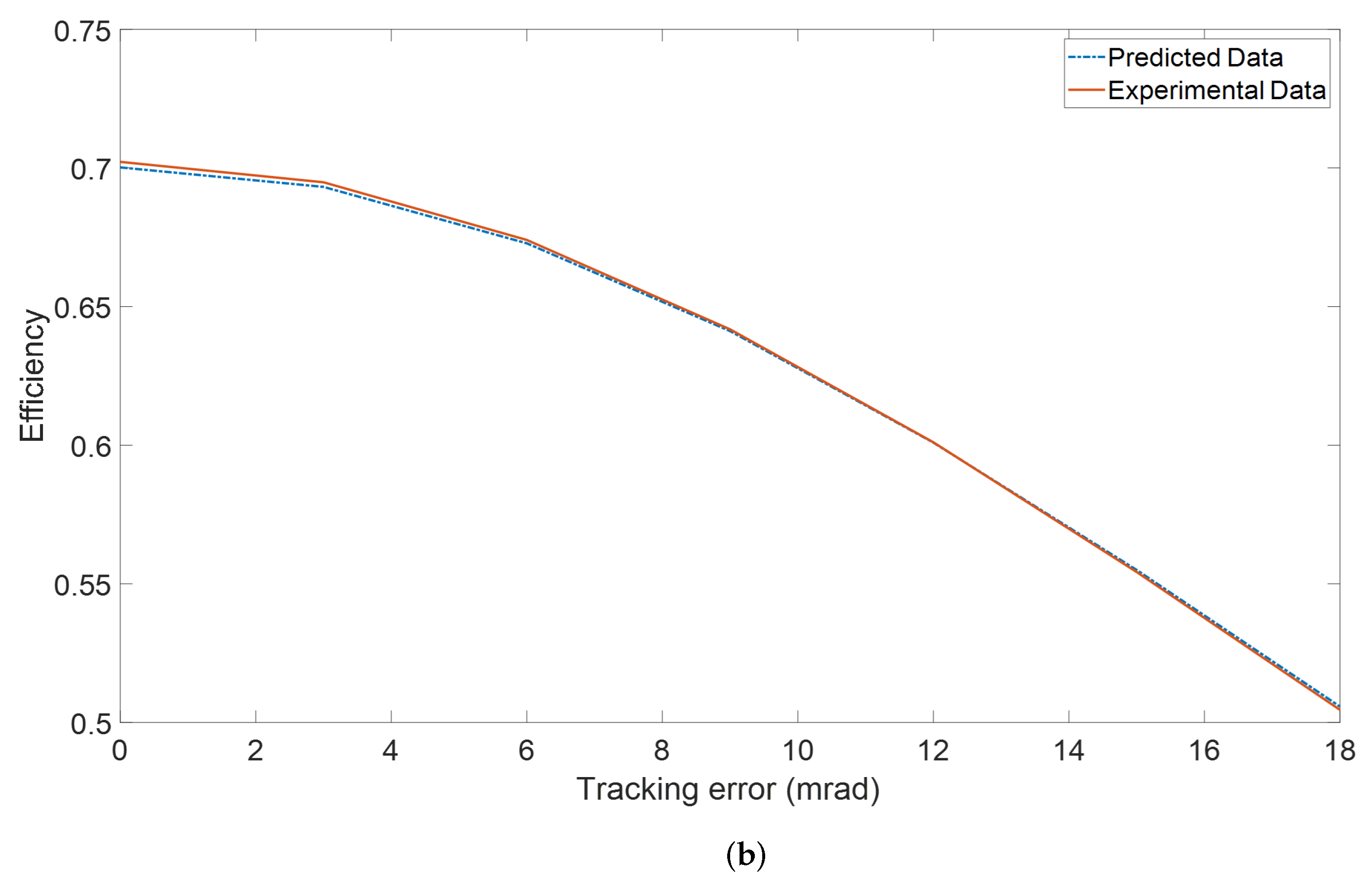
Comparison of experimental data with the predicted data is shown in Figure 1. The simulation value and test result from SolTrace have a good consistency under tracking error from 0 to 18 mrad, the absolute deviation between the simulated calculation and the test result is within 0.21%. After taking into account the reflectivity and the transmissivity of outer receiver tube, the optical efficiency of the system obtained by SolTrace is also very consistent with the simulation results. Therefore, the optical model in this paper can be applied for calculating the performance of the trough solar system under different tracking error.

4. Results and Discussion

Here, we calculate parabolic trough solar system with parameters which are listed in Table 1. The sun position calculated with the SPA proposed by NREL are assumed to be real sun position and compared with other results of other SPAs with larger uncertainties to compute the tracking error at any moment. We assume it is sunny every day to simplify the model.

4.1. Comparison of Error Distribution of SPAs and Their Influence on Performance of System

Evaluating the influence of errors of SPAs on the efficiency of trough system requires the calculation of the error of the algorithm at every moment, which usually takes considerable time and effort. Different SPAs have different calculation principles and therefore have different error distributions, taking one year as the cycle. We consider calculating the average error of SPAs and use it to evaluate the effort of error of SPA. In this paper, we choose SPAs with different accuracies and evaluate the influence of error of those SPAs on the efficiency of system by calculating the tracking error caused by those algorithms under different tracking modes [7,9,13,14,15,16,17,18,19,20].
The algorithms proposed in some studies only include the calculation of solar declination or equation of time. In this paper, we combine those algorithms with similar errors to calculate the tracking error, such as the solar declination method proposed by Cooper [14] and equation of time method proposed by Woolf [13], the solar declination method proposed by Stine [19] and equation of time method proposed by Whillier [20], and the solar declination method proposed by Bourges [17] and the equation of time method proposed by Lamm [16]. Algorithms mentioned in this paper also include those proposed by Spencer [7], Grena [9] and Huang [15]. We assume those algorithms are used by tracking systems of the trough solar system and calculate tracking error generated by those algorithms.
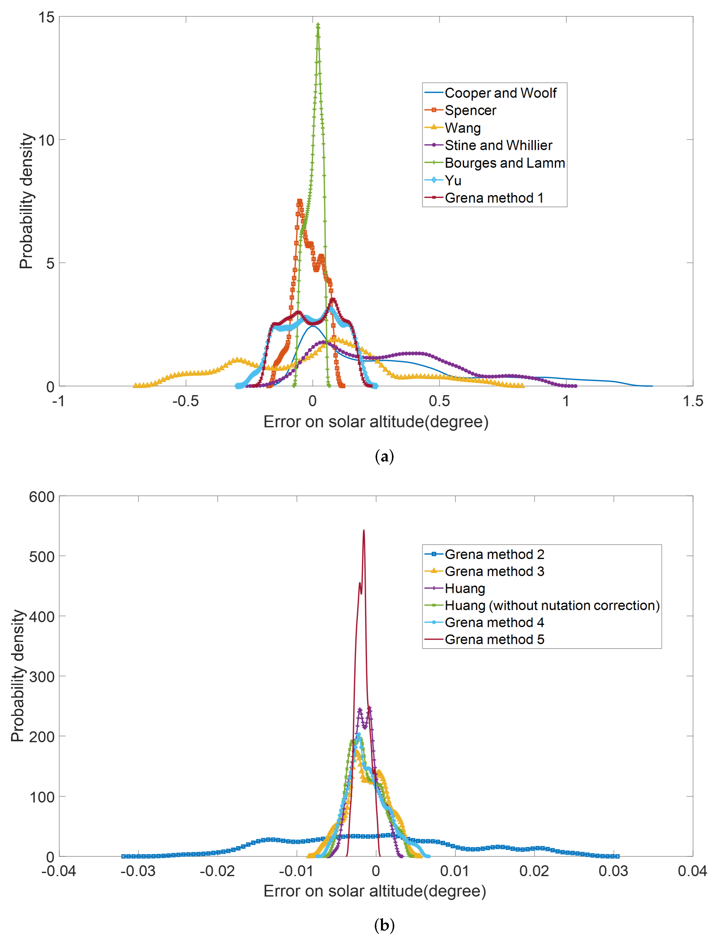
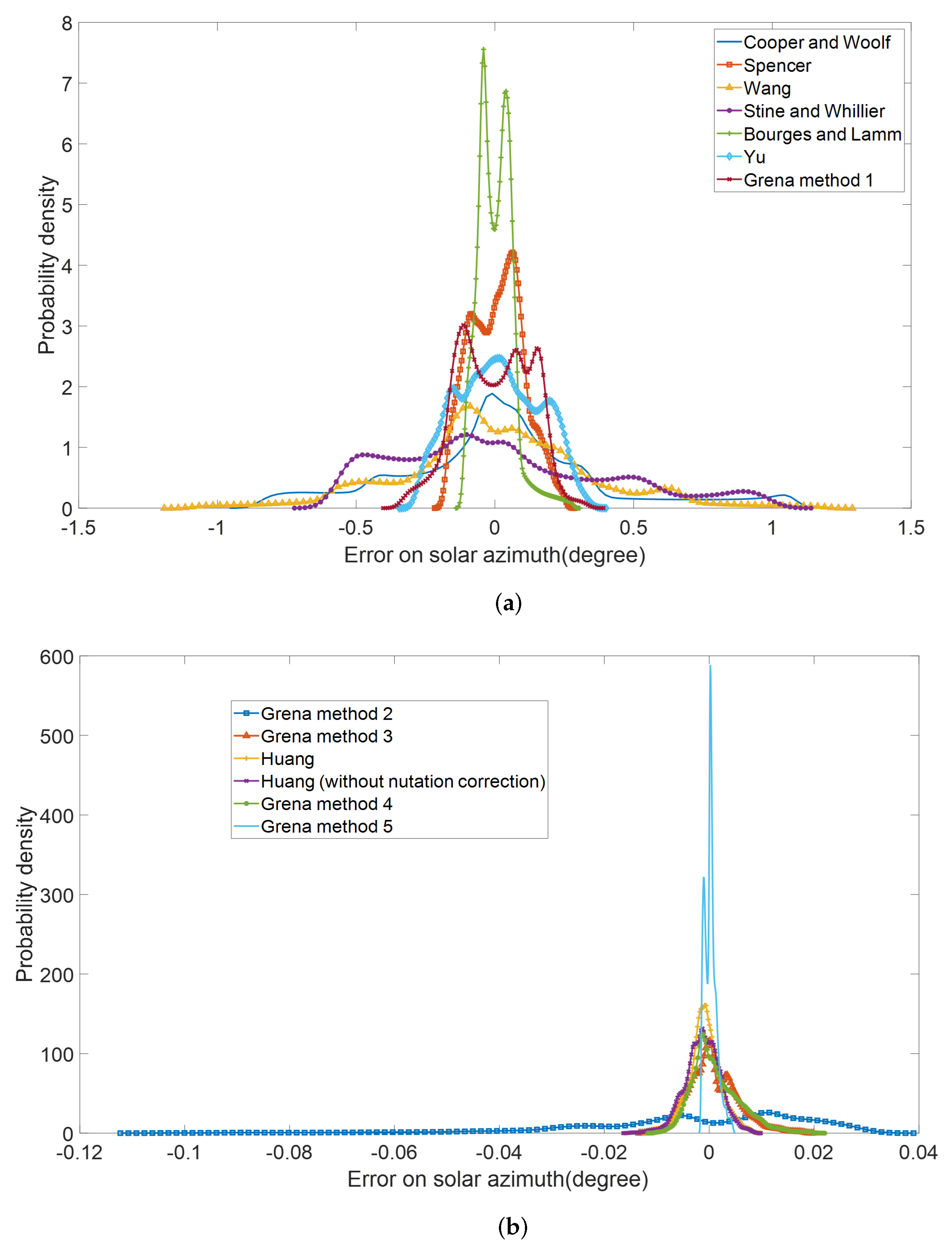
As shown in Figure 2 and Figure 3, in order to clearly display the error range and distribution of various algorithms within a year, we calculate the distribution of error on solar altitude and error on solar azimuth in comparison with the result obtained at different times in 2020 with those SPA methods. For every day, 160 times are computed, from 7:12 am to 4:48 pm solar time, every 3.6 min. The latitude of calculated position is 37.1 and the longitude is −2.36. The maximum errors of solar altitude and solar azimuth angle of the empirical algorithm are bigger than 1°, and the maximum errors of the sophisticated algorithms are less than 0.05°. For all algorithms, the azimuth error is generally greater than the altitude error. Table 2 shows these SPAs and the annual average absolute error of azimuth γ , Zenith angle α and hour angle ω , the corresponding annual average absolute tracking error is also given. Among those algorithms, the algorithm proposed by Grena has the lowest error. The average azimuth error is only 0.012 mrad, and the tracking error is less than 0.03 mrad, which is negligible for the line focusing parabolic trough system. The tracking error under polar axis tracking mode is approximately equal to the time angle error, and the tracking error under east–west axis and north–south axis mode can be calculated using the formula proposed in Section 2.2. The error under the east–west axis tracking mode and polar axis tracking mode is obviously lower than the result under the north–south axis tracking mode.The variance of absolute error of the solar azimuth and altitude are given. The results show that in most cases, algorithms with lower accuracy have lager variance. The algorithms with the greatest variance are Cooper algorithm and Stine algorithm, and the value can reach 25 mrad2. Table 2 also shows the calculation consumption of these algorithms, which is calculated by the method proposed by Grena [9]. The average error of azimuth can be easily reduced to less than 1 mrad with about 450 calculation consumption.
To evaluate the effect of tracking error on the efficiency of trough solar system, we need to take tracking error into the calculation program and calculate the efficiency at every moment. In Table 3, we take the Cooper and Woolf algorithm as an example and draw a comparison between the parabolic trough efficiency affected by error of SPA and the efficiency without tracking error on the spring equinox, summer solstice, autumn equinox and winter solstice under three tracking methods. Under the north–south axis tracking method, the tracking error range is from 0.0065 to 5.52 mrad. With the effect of tracking error, the efficiency decreased by 14.81% on the spring equinox, 0.18% on the summer solstice and 31.12% on the autumnal equinox. The tracking error of parabolic trough system under the three tracking modes is different in a year. Compared with the north–south axis tracking mode, the east–west axis tracking mode always has smaller tracking error, with the range from 0.52 to 5.61 mrad, especially in spring and autumn. The above results show that Cooper and Woolf algorithms have large errors and have a great impact on the trough system, which cannot meet the requirements of trough system tracking. See the results listed in Table 3. Due to the different calculation principles of the sun position algorithm, the errors of the same algorithm in different seasons are often different, but the changes of the tracking error and the sun position error in all tracking modes show a positive correlation trend.
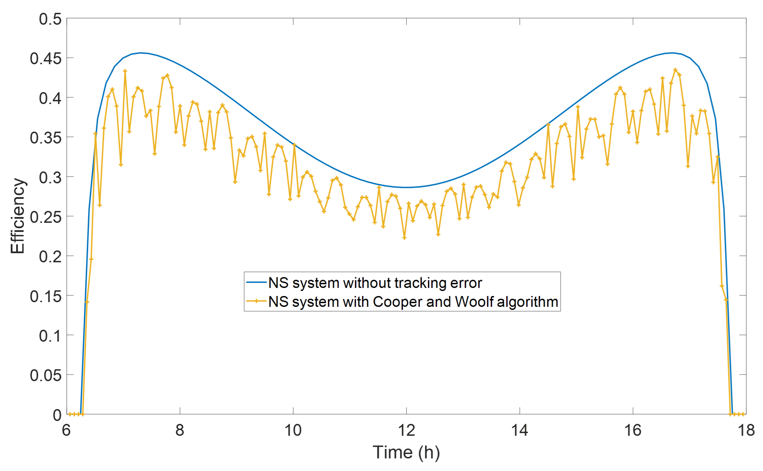
When these algorithms are applied in the tracking system, the tracking error caused by them will affect the performance of system. We make a comparison of two system with this algorithm and another system without tracking error under the north–south modes at the spring equinox, as shown in Figure 4. At the spring equinox, the system with the Spencer and Woolf algorithm had the lower performance, with an average efficiency of 0.32 with an average error of 9.05 mrad. At the same time, the efficiency of the system without tracking error was 0.3636. Therefore, 12% of efficiency is lost due to the error of the algorithm. Table 3 presents the average efficiency lost by the Spencer and Woolf algorithm for three tracking systems in four different days. From Figure 2 and Table 3, it can be seen that efficiency lost by the Spencer and Woolf algorithm varied in rather complicated ways at different moments. This is because the error distribution of SP algorithm is much complicated and variable, which can be seen from Figure 2 and Figure 3. The precise evaluation of the efficiency influence caused by the SPA may need each moment calculation which are very large. Therefore, it is necessary to develop a simple and convenient method to evaluate the error influence of the SPA.

4.2. The Error Caused by Using Average Error to Evaluate the Effect of SPA’s Error on Trough Solar System

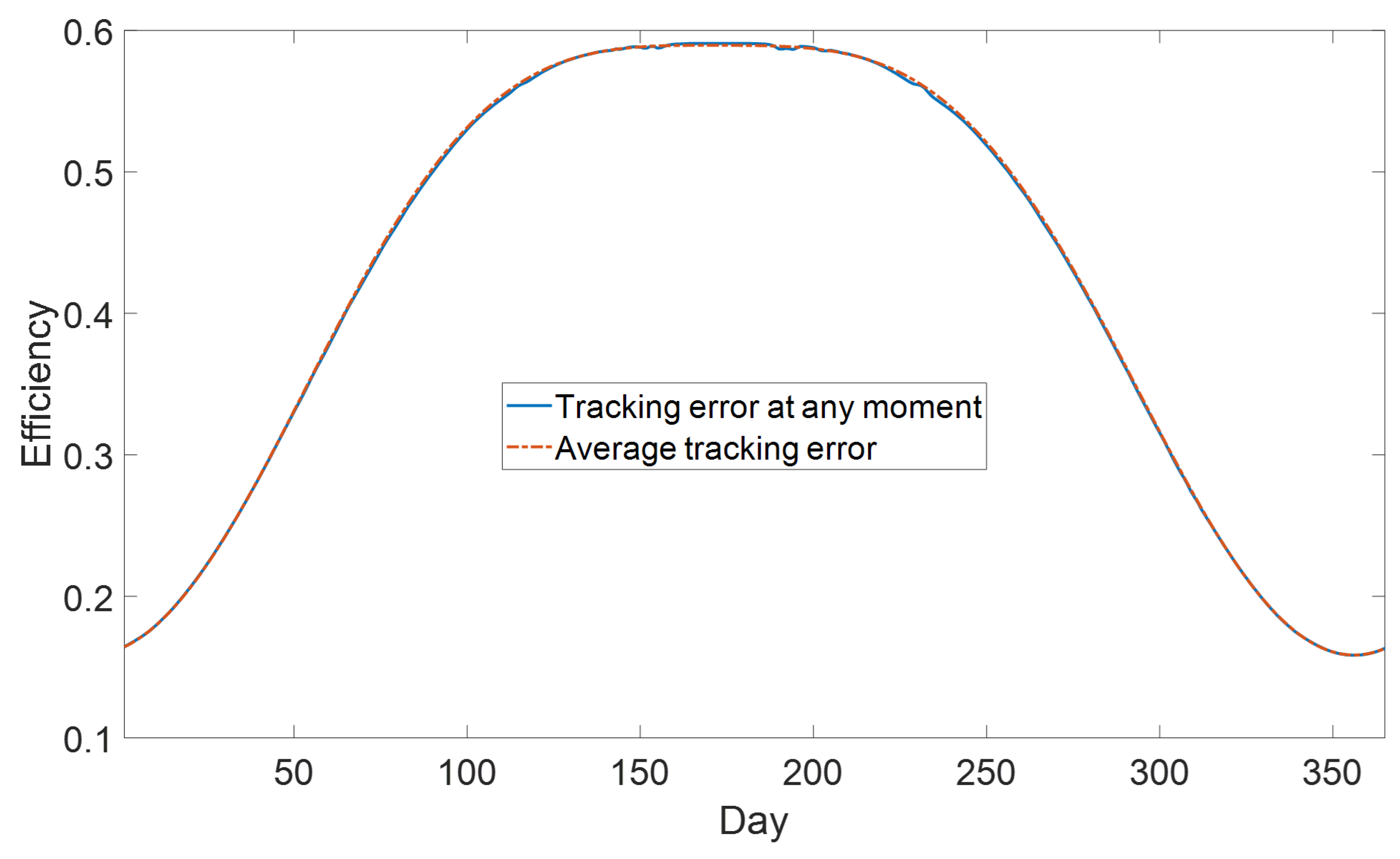
In practical application, due to the processor performance of the tracking system of a parabolic trough system, the algorithm with low computation will be preferred, thus, it will produce tracking error at every moment. When we consider the impact of this SPA on efficiency, the average error can usually be taken as a reference. However, the tracking error caused by error of SPA always changes at every moment. The calculation method that takes the average error as tracking error will increase the efficiency calculation error. Figure 5 shows the comparison of the annual average efficiency calculated directly using the Bourges and Lamm algorithm and result using the average error under the north–south tracking mode. The annual average efficiency obtained under the two calculation methods are 0.4214 and 0.4330, respectively. The efficiency calculated by using the average error is 0.13% higher than that consider the error of every moment, which is quite small.
When the algorithm with higher error is adopted, the tracking error will have greater fluctuation, and the average error calculation method may lead to larger error. In Table 4, we calculate its annual average optical efficiency while taking the annual average error of Cooper and Woolf algorithm as the fixed tracking error of parabolic trough system. Under the north–south axis tracking mode, the efficiency decreases by 7.14% because of tracking error, the east–west axis efficiency decreases by 3.34%, and the polar axis efficiency decreases by 3.03%. The tracking error of the north–south tracking mode is higher, and the error introduced is greater when we apply the average error to characterize the impact of the tracking error. In the north–south axis, east–west axis and polar axis tracking modes, the relative differences of efficiency obtained by using the average are 0.0116, 0.0071 and 0.0048, respectively. This shows that when the error of SPA is large, we replace the tracking error with a fixed average error, introducing a large calculation error, the maximum error is close to 2.75%. Cooper and Woolf algorithms have large error which is not suitable for trough systems, so this will not affect the application of average error calculation method in trough systems.
Table 5 shows the comparison of efficiency with other SPAs under the north–south tracking mode. The result calculated with average error has error of less than 0.18% when the average error is less than 1.3 mrad, and the introduced error can be ignored. When the error is from 1.3 to 2.4 mrad, the difference between the efficiency calculated with the average error and the error at every moment is 0.18–0.74%, which will have a slight impact on the result. When the annual average tracking error of the parabolic trough system applying SPA reaches 4.2 mrad, the efficiency of the parabolic trough system is reduced by 5.42%. When the average error is applied, the efficiency is reduced by 2.69%, and the absolute error is 2.89%. The absolute error between those two calculation method is 3.65%, which obviously cannot be ignored. However, at the same time, the efficiency of trough solar system is greatly affected by tracking error, and this algorithm is not suitable for the trough system any more. The result above shows that when the SPA is suitable for the trough system, the average error is less than 2.5 mrad. The difference between the two calculation method is small. It is considerable to evaluate the influence of tracking error to performance of trough solar system by using average error instead in order to simplify the calculation.

5. Conclusions

In this paper, the average tracking error of SPA is proposed to represent its error influence on the solar trough system. We compute the efficiency of the solar trough system with tracking error generated by error of SPAs for each moment over a year and efficiency when average error of SPA is applied. The average efficiency difference of two calculation methods over a year is evaluated for solar trough system.
We compute the calculation error of serval of SPAs by comparing to the SPA proposed by NREL and its contribution to tracking error of parabolic trough solar system under three tracking strategy. For the efficiency calculation, we improved the calculation program of the optical efficiency of the trough system developed before [11], taking the change of the focus position caused by the tracking error into account. Due to the lack of relevant experimental data, SolTrace was used to verify the model. ’the annual efficiency of a solar system with main SPAs is given and the influence of their errors on the system efficiency is calculated with the program of optical efficiency for solar trough. We also make an efficiency comparison calculated with fixed annual average tracking error and normal constantly changing tracking error within a year for each solar trough system, and the main conclusions are as follows:
  • When the average error of SPAs is used to characterize the impact of its error on system efficiency, it is a good approximation for most algorithms. Compared with the result of parabolic trough system that calculate the error of every moment, the efficiency obtained is quite similar, and most of the relative errors are of less than 0.5%;
  • For the low-precision SPAs with an annual average error higher than 1.5 mrad, the relative error is within the range of 0.5% to 3% when the average error is used to evaluate its impact on the efficiency of the trough system. Most of them are less than 1%, which can represent the influence of SPA algorithm error on the performance of the system;
  • The average error of SPAs is used to represent its precision characteristics. The disadvantage is that for a few algorithms with low complexity, it cannot reflect its annual periodic tracking error changes. In some moments, the error is very small, while in others, the error is large, which introduces larger error of the instantaneous efficiency.
Overall, the average error of the SPA is used to evaluate its impact on the efficiency of the solar trough system. The advantage is that the calculation of tracking error can be simplified without the calculation of high precision SPA, thus can decrease the computational complexity, and for most SPAs, the accuracy is quite good. However, for a few empirical algorithms with large errors, they not only introduce large annual average errors, but also present larger errors for the calculation of the instantaneous efficiency when they are used for the trough system, which shows they are not suitable for solar trough system, in particular, the Cooper algorithm, Stine algorithm and Wang algorithm. Whether this evaluation method is applicable to other solar energy systems requires further study.

Author Contributions

Conceptualization, B.L. and W.H.; methodology, B.L. and W.H.; software, B.L.; validation, B.L. and W.H.; formal analysis, B.L. and W.H.; resources, W.H.; data curation, B.L.; writing—original draft preparation, B.L.; writing—review and editing, B.L.; supervision, W.H. and C.Z.; project administration, W.H. All authors have read and agreed to the published version of the manuscript.

Funding

This research received no external funding.

Institutional Review Board Statement

Not applicable.

Data Availability Statement

Not applicable.

Acknowledgments

The part of numerical calculations in this paper has been done on the supercomputing system in the Supercomputing Center of University of Science and Technology of China.

Conflicts of Interest

The authors declare no conflict of interest.

Nomenclature

a 0 , a 1 , a 2 , a 3 , b 0 , b 1 parameter for calculating the heat loss of receiver
B e f f ( θ ) the energy distribution function of reflected ray in radial direction (W/m2/rad)
B l i n e a r ( θ ) linear brightness distribution function at transverse direction (W/m2/rad)
D N I direct normal incidence (W/m2)
Etotal DNI energy in a year (J/m2)
f 0 focus length (m)
f p distance from the reflection point to the focus point (m)
Llength of the parabolic mirror (m)
q l o s s heat loss of receiver (W/m2)
q n e t net energy power in any time (W/m2)
Rradius of envelope for vacuum tube receiver (m)
r 0 radius of the tube receiver (m)
Ttemperature of receiver (K)
ttime (day)
whalf width of the trough mirror (m)
zzenith
α absorptivity of vacuum receiver
γ azimuth
ρ reflectivity of mirror
τ transmittance of glass envelope
φ rim angle of the reflection point (rad)
ω timeangle (rad)
lgeographical latitude (rad)
δ solar declination (rad)
θ angular displacement in longitudinal direction (rad)
θ angular displacement in transverse direction (rad)
θ 0 maximum angle of ray to the receiver (rad)
σ o p t i c optical error (rad)
σ t r a c k i n g tracking error (rad)
η the optical efficiency of parabolic trough solar collector

References

  1. Thomas, A. Solar steam generating systems using parabolic trough concentrators. Energy Convers. Manag. 1996, 37, 215–245. [Google Scholar] [CrossRef]
  2. Fuentes-Morales, R.F.; Diaz-Ponce, A.; Peña-Cruz, M.I.; Rodrigo, P.M.; Valentín-Coronado, L.M.; Martell-Chavez, F.; Pineda-Arellano, C.A. Control algorithms applied to active solar tracking systems: A review. Sol. Energy 2020, 212, 203–219. [Google Scholar] [CrossRef]
  3. Blanco-Muriel, M.; Alarcón-Padilla, D.C.; López-Moratalla, T.; Lara-Coira, M. Computing the solar vector. Sol. Energy 2001, 70, 431–441. [Google Scholar] [CrossRef]
  4. Praveenkumar, S.; Gulakhmadov, A.; Kumar, A.; Safaraliev, M.; Chen, X. Comparative Analysis for a Solar Tracking Mechanism of Solar PV in Five Different Climatic Locations in South Indian States: A Techno-Economic Feasibility. Sustainability 2022, 14, 11880. [Google Scholar] [CrossRef]
  5. Hafez, A.Z.; Yousef, A.M.; Harag, N.M. Solar tracking systems: Technologies and trackers drive types—A review. Renew. Sustain. Energy Rev. 2018, 91, 754–782. [Google Scholar] [CrossRef]
  6. Chen, W.; Li, J. Optical performance analysis for parabolic-trough focusing collector with several tracking modes. Taiyangneng Xuebao/Acta Energiae Solaris Sin. 2003, 24, 477–482. [Google Scholar] [CrossRef]
  7. Spencer, J.W. Fourier series representation of the position of the Sun. Search 1971, 2, 165–172. [Google Scholar]
  8. Blanco, M.J.; Milidonis, K.; Bonanos, A.M. Updating the PSA sun position algorithm. Sol. Energy 2020, 212, 339–341. [Google Scholar] [CrossRef]
  9. Grena, R. Five new algorithms for the computation of sun position from 2010 to 2110. Sol. Energy 2012, 86, 1323–1337. [Google Scholar] [CrossRef]
  10. Reda, I.; Andreas, A. Solar position algorithm for solar radiation applications. Sol. Energy 2004, 76, 577–589. [Google Scholar] [CrossRef]
  11. Huang, W.; Hu, P.; Chen, Z. Performance simulation of a parabolic trough solar collector. Sol. Energy 2012, 86, 746–755. [Google Scholar] [CrossRef]
  12. Patnode, A.M. Simulation and Performance Evaluation of Parabolic Trough Solar Power Plants; University of Wisconsin Madison: Madison, WI, USA, 2006. [Google Scholar]
  13. Woolf, H.M. On the Computation of Solar Elevation Angles and the Determination of Sunrise and Sunset Times. 1968. Available online: https://ntrs.nasa.gov/api/citations/19680025707/downloads/19680025707.pdf (accessed on 1 June 2022).
  14. Cooper, P.I. The absorption of radiation in solar stills. Sol. Energy 1969, 12, 333–346. [Google Scholar] [CrossRef]
  15. Huang, W.; Liu, B. Solar Position Algorithm Based on the Kepler Equation. Appl. Sci. 2022, 12, 5449. [Google Scholar] [CrossRef]
  16. Lamm, L.O. A new analytic expression for the equation of time. Sol. Energy 1981, 26, 465. [Google Scholar] [CrossRef]
  17. Bourges, B. Improvement in solar declination computation. Sol. Energy 1985, 35, 367–369. [Google Scholar] [CrossRef] [Green Version]
  18. Wang, B.; Tang, J. Comparsion of the different methods for solar position calculation. Taiyangneng Xuebao/Acta Energiae Solaris Sin. 2001, 4, 50–54. [Google Scholar] [CrossRef]
  19. Stine, B. Solar Energy Fundamental and Design; John, Wiley & Sons, Inc.: Hoboken, NJ, USA, 1985. [Google Scholar]
  20. Du, C.; Wang, P.; Ma, C.; Wu, Y. The application of day number in calculating the solar position. Taiyangneng Xuebao/Acta Energiae Solaris Sinica 2011, 32, 1640–1645. [Google Scholar]
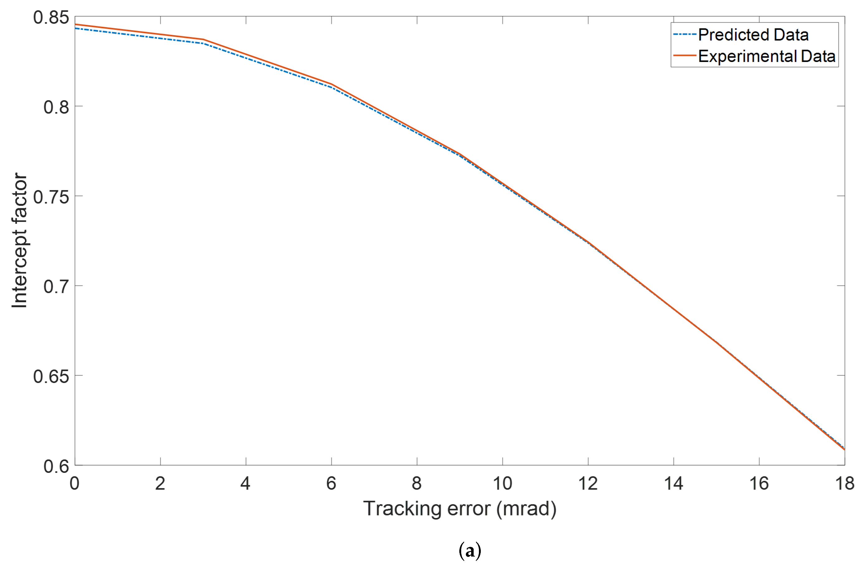
Figure 1. Comparison between predicted result and experimental data; (a) The intercept factor of parabolic trough solar system calculated by program and SolTrace under different tracking error. (b) The efficiency of parabolic trough solar system calculated by program and SolTrace under different tracking error.
Applsci 13 01821 g001aApplsci 13 01821 g001b
Figure 2. The probability density distribution of the calculation error of solar altitude; (a) Solar position empirical algorithm. (b) Solar position complex algorithm.
Applsci 13 01821 g002
Figure 3. The probability density distribution of the calculation error of solar azimuth. (a) Solar position empirical algorithm. (b) Solar position complex algorithm.
Applsci 13 01821 g003
Figure 4. Efficiency comparison of two parabolic trough system with tracking error generated by the Cooper and Woolf method and without tracking error condition, respectively, under NS tracking system at the spring equinox; NS: north–south axis tracking system.
Applsci 13 01821 g004
Figure 5. Efficiency comparison of two system calculated with tracking error at every moment and average tracking error, respectively, with the Bourges and Lamm method under north–south axis tracking system.
Applsci 13 01821 g005
Table 1. Parameter of the typical parabolic trough solar collector.
ParameterData
Focus length f 0 1.7 m
Half trough width w3 m
Length of trough L100 m
Radius of receiver tube r 0 0.035 m
Radius of envelope of receiver R0.055 m
Operation temperature of receiver T400 °C
Transverse optical error θ 6 mrad
Longitudinal optical error θ 6 mrad
Table 2. The annual average tracking error and annual average error of the solar azimuth, solar altitude and variance thereof and hour angle of SPAs with different accuracy and computational cost values. NS: north–south axis tracking system, EW: east–west axis tracking system.
(a) Solar Position Empirical Algorithm
SPAsComputational
Cost
Tracking
Method
Annual
Average
Tracking Error
(mrad)
Annual
Average Error
of the Solar
Azimuth
(mrad)
Variance of
Absolute Error
of the Solar
Azimuth
(mrad2)
Annual
Average Error
of the Solar
Altitude
(mrad)
Variance of
Absolute Error
of the Solar
Altitude
(mrad2)
Annual
Average Error
of the Hour
Angle (mrad)
Cooper and Woolf319NS5.756.9425.6185.0632.082.88
EW3.11     
Polar axis2.88     
Spencer397NS2.444.4710.372.061.7943.37
EW1.47     
Polar axis3.37     
Stine and Whillier335NS6.038.4825.755.1917.7164.93
EW3.28     
Polar axis4.93     
Bourges and Lamm456NS1.331.681.0961.160.5770.89
EW0.78     
Polar axis0.89     
Wang388NS4.225.0516.0153.798.8331.9
EW2.76     
Polar axis1.9     
Yu327NS2.434.166.0562.081.2042.84
EW1.6     
Polar axis2.84     
Grena method 1428NS1.823.182.9221.560.7872.28
EW1.3     
Polar axis2.28     
(b) Solar Position Complex Algorithm
SPAsComputational
Cost
Tracking
Method
Annual
Average
Tracking Error
(mrad)
Annual
Average Error
of the Solar
Azimuth
(mrad)
Variance of
Absolute Error
of the Solar
Azimuth
(mrad2)
Annual
Average Error
of the Solar
Altitude
(mrad)
Variance of
Absolute Error
of the Solar
Altitude
(mrad2)
Annual
Average Error
of the Hour
Angle (mrad)
Grena method 2455NS0.220.260.07250.170.01330.26
EW0.17     
Polar axis0.26     
Grena method 3572NS0.050.0520.00300.040.00300.053
EW0.037     
Polar axis0.053     
Huang (with
nutation correction)
765NS0.0460.0460.110.0390.000470.05
EW0.035     
Polar axis0.05     
Huang (without
nutation correction)
701NS0.0560.0540.00150.0470.0006150.055
EW0.04     
Polar axis0.055     
Grena method 4641NS0.0450.0490.00330.0360.000660.051
EW0.034     
Polar axis0.051     
Grena method 5929NS0.030.0120.00020.0320.000190.025
EW0.021     
Polar axis0.025     
Table 3. At spring equinox, summer solstice, autumn equinox and winter solstice, efficiency of parabolic trough system with the Cooper and Woolf method and efficiency of system without tracking error under different tracking methods.
Tracking MethodTimeEfficiency of
System without
Tracking Error
Efficiency of
System with
Cooper and Woolf
Method
Daily Average
Tracking Error
(mrad)
north–south axis
tracking system
Spring Equinox0.4320.3689.13
Summer Solstice0.5580.5570.47
Autumn Equinox0.4370.30113.85
Winter Solstice0.1420.1372.05
east–west axis
tracking system
Spring Equinox0.2720.2613.63
Summer Solstice0.2520.2520.52
Autumn Equinox0.2690.2485.61
Winter Solstice0.35610.35431.3
polar axis
tracking system
Spring Equinox0.5810.5791.36
Summer Solstice0.4790.4780.77
Autumn Equinox0.580.5742.38
Winter Solstice0.4780.4742.04
Table 4. Average annual tracking error and efficiency of system with the Cooper and Woolf method under three different tracking methods, efficiency calculated with average tracking error and the relative difference between two results.
Tracking
Methods
Efficiency
without
Tracking Error
Efficiency with
Cooper and
Woolf Method
Average Annual
Tracking Error
(mrad)
Efficiency
Calculated with
Average
Tracking Error
The Relative
Difference
North-South axis0.45380.42145.50.43302.75%
East-West axis0.34470.33322.90.34032.13%
Polar axis0.56170.562.70.55520.86%
Table 5. Average annual tracking error and efficiency of system with Cooper and Woolf method under three different tracking methods, efficiency calculated with average tracking error and the relative difference between two results.
SPAsEfficiency
Calculated with
Average Tracking
Error
Efficiency
Calculated with
Tracking Error at
Every Moment
Average Tracking
Error (mrad)
The Relative
Difference
Cooper and Woolf0.43300.42145.52.75%
Stine and Whillier0.42910.414063.65%
Wang0.44160.42924.22.89%
Spencer0.44940.44692.40.56%
Yu0.44980.44652.40.74%
Bourges and Lamm0.45260.45181.30.18%
Grena method 10.45150.44991.80.35%
Grena method 20.45370.45360.220.02%
Grena method 30.45380.45380.0490%
Grena method 40.45380.45380.0450%
Grena method 50.45380.45380.0030%
Huang (without nutation correction)0.45380.45380.0560%
Huang (with nutation correction)0.45380.45380.0460%
Disclaimer/Publisher’s Note: The statements, opinions and data contained in all publications are solely those of the individual author(s) and contributor(s) and not of MDPI and/or the editor(s). MDPI and/or the editor(s) disclaim responsibility for any injury to people or property resulting from any ideas, methods, instructions or products referred to in the content.