Article

Experimental and Numerical Studies on the Impact Energy Absorption of Cutting Shear Rings

1
School of Traffic & Transportation Engineering, Central South University, Changsha 410017, China
2
Key Laboratory of Traffic Safety on Track, Ministry of Education, Changsha 410075, China
3
Joint International Research Laboratory of Key Technology for Rail Traffic Safety, Changsha 410075, China
4
National & Local Joint Engineering Research Center of Safety Technology for Rail Vehicle, Changsha 410075, China
5
Department of Special Technology, Army Special Operations College, Guilin 541000, China
*
Author to whom correspondence should be addressed.
Appl. Sci. 2023, 13(3), 1860; https://doi.org/10.3390/app13031860
Submission received: 16 November 2022 / Revised: 23 January 2023 / Accepted: 27 January 2023 / Published: 31 January 2023

Abstract

:
To improve the passive safety of the collision process, we designed a kind of energy absorption device based on cutting shear rings (CSR). It can be installed in a limited space, overcoming the characteristic of traditional energy absorption devices that cannot play their advantages in a narrow space, and it will not be accompanied by the splashing of chips in the process of energy absorption. The impact energy absorption characteristics of the shear rings outside the energy absorption rods are analyzed. The feasibility of the finite element method to study the device’s characteristics is demonstrated through the combination of the drop hammer test and numerical simulation. At the same time, the device’s responses under nine different working cases are simulated, and the impact energy absorption characteristics of the shear rings are analyzed. Moreover, the effects of shear ring thickness and spacing on the device are also analyzed. The results show that there are several peak forces during the energy absorption process, and each peak force is accompanied by the failure of the shear ring. The shear rings’ thickness correlates positively with energy absorption and peak force. But the spacing of shear rings only affects the number of peak forces. There is a linear trend between the shear rings’ spacing and energy absorption, and the slope of the trend increases with the increase in thickness.

1. Introduction

As early as the 1960s, the British Railway (BR) proposed the concept of collision mitigation and energy absorption. Subsequently, many scholars carried out relevant research and acquired a lot of achievements [1,2]. At present, the energy absorption devices extensively used to enhance passive safety are mainly divided into two types: the fracture type and the crushing type. The fracture-type devices refer to the use of friction between the inner and outer tubes when bearing axial impact through the extrusion of the outer tube to make it crack or crack part of the curling deformation to achieve energy absorption, usually in a tube-in-tube structure. The crushing-type devices mainly use the excellent energy absorption effect of metal materials to achieve the purpose of collision mitigation when subjected to axial impact, which is primarily divided into thin-walled tubular, honeycomb, and mesh metal structures [3,4,5].
In particular, thin-walled tubular and honeycomb structures are extensively used in various collision energy absorption processes to reduce the impact load and improve the crashworthiness of the structure [6,7,8,9]. The thin-walled structures exhibit excellent performance under dynamic loads and have the advantages of cost-effectiveness and high efficiency, and their energy absorption capacity is closely related to the structure’s geometry, material type, and load form [10,11]. In recent years, Reddy [12], Li [13], Sun [14], Mousanezhad [15], et al. researched the energy absorption characteristics and structural optimization of thin-walled structures through different methods, and their related theories and results have been applied to the design of energy absorption devices. Meanwhile, by comparing the response characteristics of thin-walled structures under different impact loads, many scholars analyzed the different failure forms of thin-walled structures [16,17,18]. In particular, under the impact of axial load on thin-walled tubular structures, the axial and lateral spaces of energy absorption decrease while the transverse space of energy absorption increases [19,20]. Therefore, it is necessary for energy absorption devices to reserve lateral deformation space. When the installation space is relatively narrow, the thin-walled structure is difficult to exploit for its superior performance.
To improve the performance of energy absorbers with higher absorbed energy, lower peak contact force, and a more stable response process, many scholars have studied the impact resistance of materials [21,22] and reformed the existing structure [23,24]. Beik et al. [25] transformed linear metal tubes into S-shaped conical tubes and introduced strengthening and deceleration technologies, which increased the absorption energy by 35% compared with linear tubes. Jung et al. [26] designed dynamic compression and impact properties of a new open-type Ni/Al composite metal foam and compared them with those of pure aluminum foam. The feasibility of Ni/Al composite foams as shock absorbers under explosion and ballistic impact is proven. Meanwhile, Cheng et al. [2] found that the energy absorption method with the combined effect of friction, plastic deformation, and tearing between metals is better than the energy absorption method with large plastic deformation of thin-walled metal materials. In other words, the energy absorption method of a cracked energy absorption structure is better than that of a crushed energy absorption structure. Chang et al. [27,28] proposed a cutting-type energy absorption device based on the principle of chip generation. The energy absorption device must be an irreversible but controllable process in the process of energy absorption. Liu et al. [29] designed a cutting energy-absorbing structure and discussed the effect of structural parameters on the response characteristics using polar difference analysis. They found that the energy absorption was strongly sensitive to the cutting depth and width. The energy absorption devices based on cutting screw thread, which were first proposed by Luo and Lei in 2003 [30,31], can achieve significant specific energy absorption (SEA). Subsequently, many scholars have conducted a lot of research on the key design parameters, lightweight, and specific applications of energy absorption systems [32,33,34,35] and have also achieved certain results. However, these previously proposed energy absorption structures have some drawbacks. During operation, most cutting energy absorbers produce irregular splashes. Energy-absorbing devices occupy a lot of space, which is also a common problem. In addition, once the structure is designed, the enhanced energy absorption performance is limited.
To solve the application of energy absorption devices in a limited space, we designed a kind of impact energy absorption based on cutting shear rings (CSR), which involved metal shearing, extrusion, and upsetting processes in the impact response. Compared to traditional energy absorption devices, CSR systems do not require lateral deformation space and do not have a splatter during operation. Firstly, this work introduces the structure of CSR, and then a series of tests are carried out on the impact energy absorption characteristics of CSR by using the drop hammer test, and the test results are used to verify the finite element model. Finally, using the verified finite element model, the key geometric parameters of CSR are studied. Through the design of CSR, it provides ideas and experience for solving the application and design of an energy absorption device in a limited space.

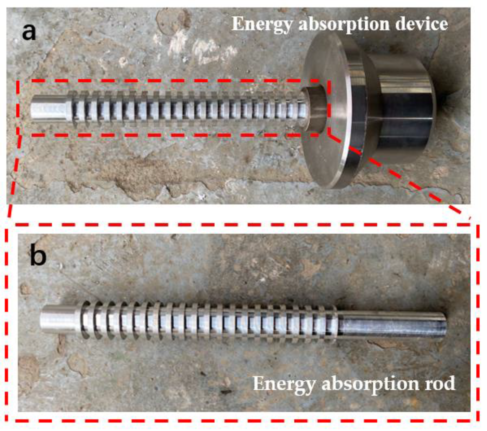
2. Design of Energy Absorption Device

At present, most energy absorption devices utilize metal damage behavior to achieve energy absorption, and irregular chip spatter can be observed in operation. In addition, energy absorption devices taking up too much space is also a common problem. In this paper, an impact energy absorption device based on CSR is designed. The CSR system absorbs energy in a variety of different ways, such as metal shearing, extrusion, and upsetting, improving metal utilization.
The CSR system consists of a pedestal and energy absorption rods. The rods are installed in the pedestal, as shown in Figure 1a. The device is connected to the external device through the pedestal. The form and fixing method of the pedestal can be determined according to the actual environment. The energy absorption rod is composed of shear rings and a guide bar and absorbs collision energy through the outer shear rings. For the CSR system, the number of energy absorption rods and the number, thickness, and spacing of external shear rings are adjusted to achieve different energy absorption sizes. At the same time, by adjusting the pedestal to reduce the thickness of the first shear ring, the initial peak force can be reduced, thus avoiding damaging the structure in the first place.
The working principle of the CSR system is shown in Figure 2, which is briefly described as follows: when the impactor hits the energy absorption rods at a certain speed, there is a trend of relative movement between the energy absorption rods and the pedestal, and the shear energy absorption process starts. By cutting off the shear rings outside of the energy absorption rods, the collision energy can be absorbed quickly.

3. Drop Hammer Test

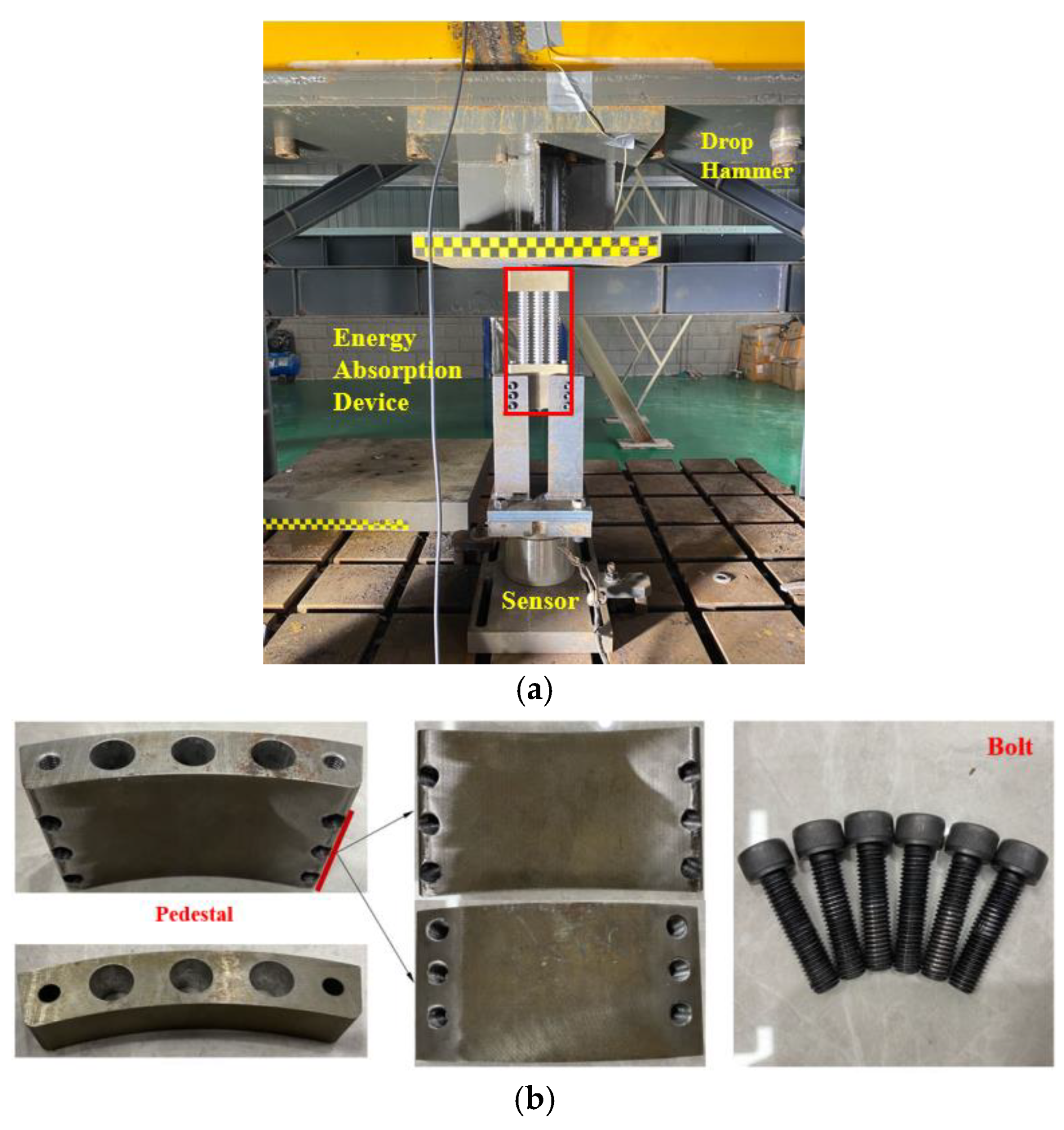
3.1. The Method of Test

The energy absorption rods prepared for the test have the same length of 243.0 mm, an inner diameter of 16.6 mm, and an outer diameter of 22.0 mm. Different impact energies can be obtained on the energy absorption devices by adjusting the drop hammer counterweight and the number of shear rings in the free fall height. For working cases 1 and 2, there are 21 shear rings outside of each energy absorption rod. Considering the influence of the gradient arrangement, the thickness of the first shear ring is 1.5 mm, and the thickness of the following 20 shear rings is 2.5 mm. For working case 3, since there are only four shear rings on the outside of each energy absorption rod, the thickness of each shear ring is 3 mm without considering the influence of the gradient arrangement.
The test site was selected on the 300 KJ drop hammer impact test platform of Transportation Engineering, Central South University, as shown in Figure 3a. The test apparatus includes a drop hammer test bench, an energy absorption device, high-speed photography, and other equipment, and the specific test apparatus is shown in Figure 3. To obtain accurate dynamic response data, the test system selected the FD-3000 dynamic load tester, which has a variety of dynamic force test functions. The instrument has a high-frequency response (100 kHz), about a thousand times that of ordinary high-speed instruments. The sampling frequency was 50 kHz during the test, and the impact process was recorded with high-speed photography.

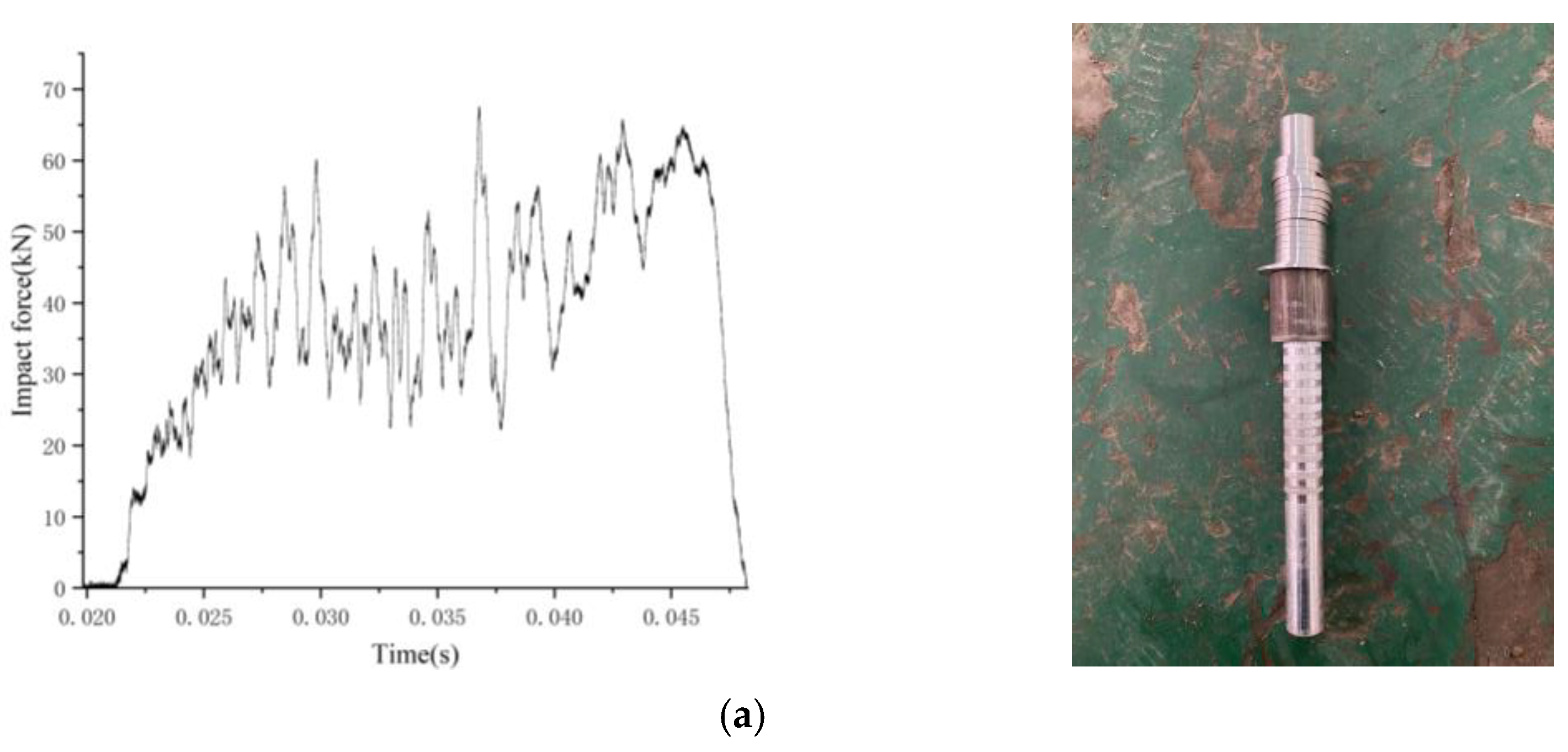
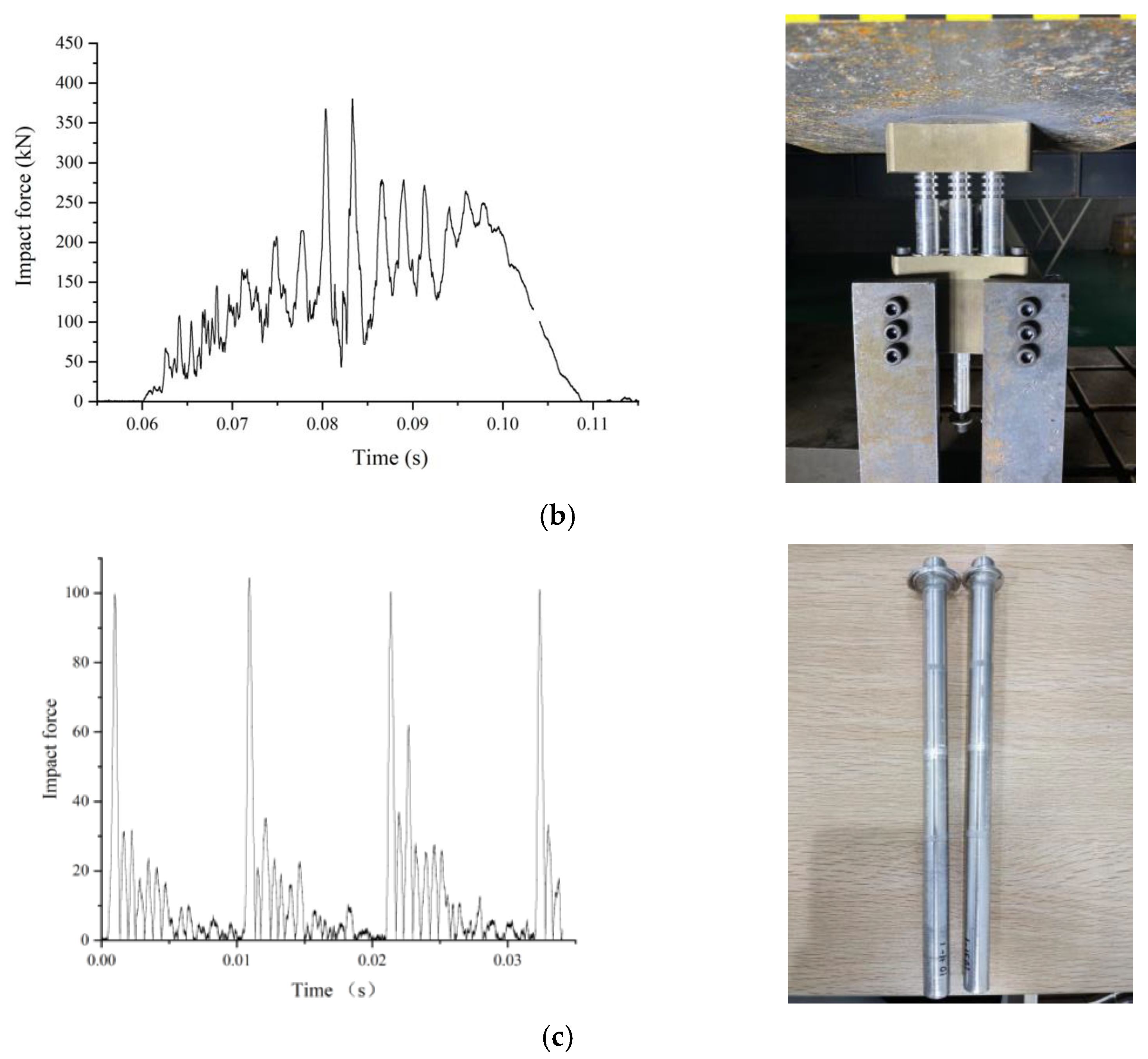
3.2. The Test Results

The test data collected by the sensor was the curve of platform force and time. To capture the energy absorbed by the device during the collision, the curve needs to be processed as follows:
I = F T d T
I = m v 1 m v 2
where I is the impulse of the platform force; F T is the platform force–time curve of the acquisition; m is the weight of the drop hammer; v 1 is the speed at which the hammer is in contact with the energy absorption rods; v 2 is the speed at which the hammer drop after the energy absorption process is completed.
To obtain the energy absorption during the collision, the following calculations are also required:
m g h = 1 2 m v 1 2
Q = 1 2 m v 1 2 1 2 m v 2 2
where h is the height of the distance between the drop hammer and the energy absorber in free fall; g is the acceleration of gravity, 9.8 m/s2; Q is the energy absorption in the collision process, and the international system of units (SI) is used in the calculation process.
The above formula is used to process the obtained test data, and the test results are obtained, as shown in Table 1. The energy absorption process of the device recorded by high-speed photography and the time–impact force curve obtained by the test system are shown in Figure 4 and Figure 5. Each peak in the curve represents a shear ring cut off by the outer cushion base. At the beginning of the energy absorption process, since the thickness of the first shear ring near the side of the buffer base is 1.5 mm, which is thinner than the thickness of the rest of the shear ring, the peak force that appears first is significantly lower than that that occurs later.
The energy absorption rods after the impact of the drop hammer are shown in Figure 5. For case 1, the maximum peak impact force is 88.01 kN, and the last shear ring is left on the outside of the energy absorption rods. The energy absorption is 2362.58 J, with an average of 118.12 J per shear ring. For case 2, the maximum peak impact force is 385.71 kN, and four shear rings are retained on the outside of each absorption rod, and the suction energy reaches 8155.56 J, with an average of 159.91 J per shear ring. For case 3, the maximum peak impact force is 104.50 kN, all shear rings on the outside of each rod are sheared, and the energy absorption is 1402.42 J, with an average of 175.30 J per shear ring.

4. Numerical Simulation

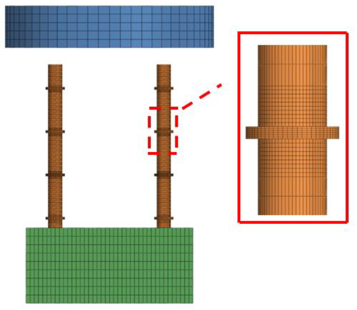
4.1. Finite Element Modeling and Material Parameters

In engineering practice, metals or fiber-reinforced composites (FRCs) are often used as energy absorption materials. The energy dissipation mechanisms of metals and FRCs are quite different. Metals absorb collision energy through their ductile point through plastic deformation. And FRCs are typically brittle and consume energy through combined fracture mechanisms such as delamination, fiber fracture, and matrix cracking [36,37]. Compared with FRCs, metals have higher specific energy absorption (SEA), lower design and cost, and meet the requirements of mass production. At the same time, due to the difficulty of recycling composite materials, metal materials have better environmental benefits [38,39]. Therefore, in most industries, metal materials are used on a much larger scale than FRCs. FRCs are used for specific engineering needs in aerospace, racing, and other industries.
Among many metal materials, aluminum alloy is a lightweight structural material with characteristics of high strength, strong corrosion resistance, and good ductility [40,41,42], which is widely used in the manufacturing process of energy absorption devices in the manufacturing of vehicles, aerospace aircraft, and other industries. Among many aluminum alloy materials, 7075 aluminum alloy has the characteristics of low density, high specific strength, good plasticity, and high impact energy absorption, and it has good comprehensive performance [43,44,45]. The 7075 aluminum alloy material was chosen for the energy absorption device. Its chemical composition and mechanical properties are shown in Table 2 and Table 3.
The method of integrated modeling was adopted in this work. The 3D model was established in SolidWorks, the mesh division and other preprocessing operations were carried out in HyperMesh, the numerical simulation model calculation was completed in LS-DYNA, and the post-processing operations were completed in LS-PrePost. To save the simulation time, the model was simplified to a certain extent. The morphology and critical size of the main components were maintained, and the details of the local position of the members, such as the bump and angle, were ignored.
The numerical model consisted of two parts, namely the impactor and the CSR system. The impact part adopted the rigid material model, and it had the same target energy as the weight in the test. The pedestal of the CSR system was made of 45 # steel, and the material parameters are shown in Table 4. To simulate the connection between the pedestal and other devices, full constraints were applied to the back of the base. The energy absorption rods material was a 7075 aluminum alloy with a density of 2810 kg/m3, an elastic modulus of 71.7 GPa, and a Poisson’s ratio of 0.33. The plastic kinematic material model was used to simulate their dynamic behavior.
The overall mesh size of the numerical model was 5 mm. In order to improve the simulation accuracy, the mesh near the shear rings was locally encrypted. The transition mesh size was 1 mm, and the shear rings mesh size was 0.5 mm. The Solid Map feature of HyperMesh was used to divide the mesh according to the principle of appeal. The total mesh number of the model is 159,831, and the mesh after division is shown in Figure 6.

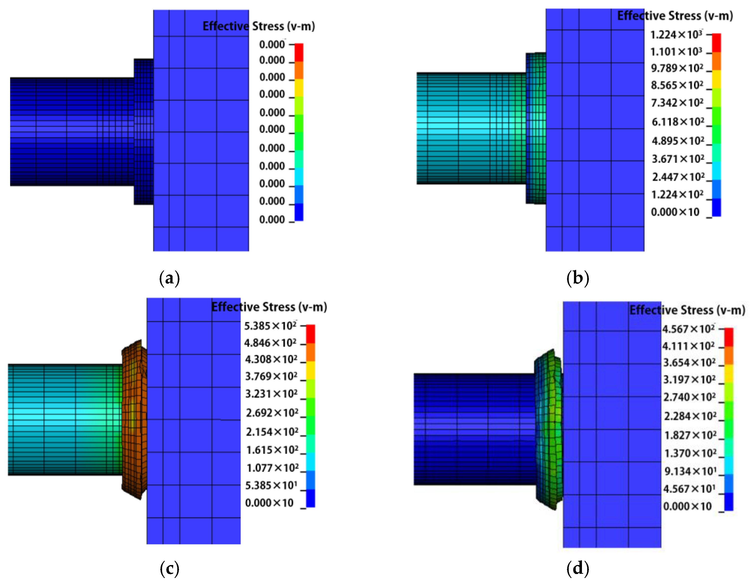
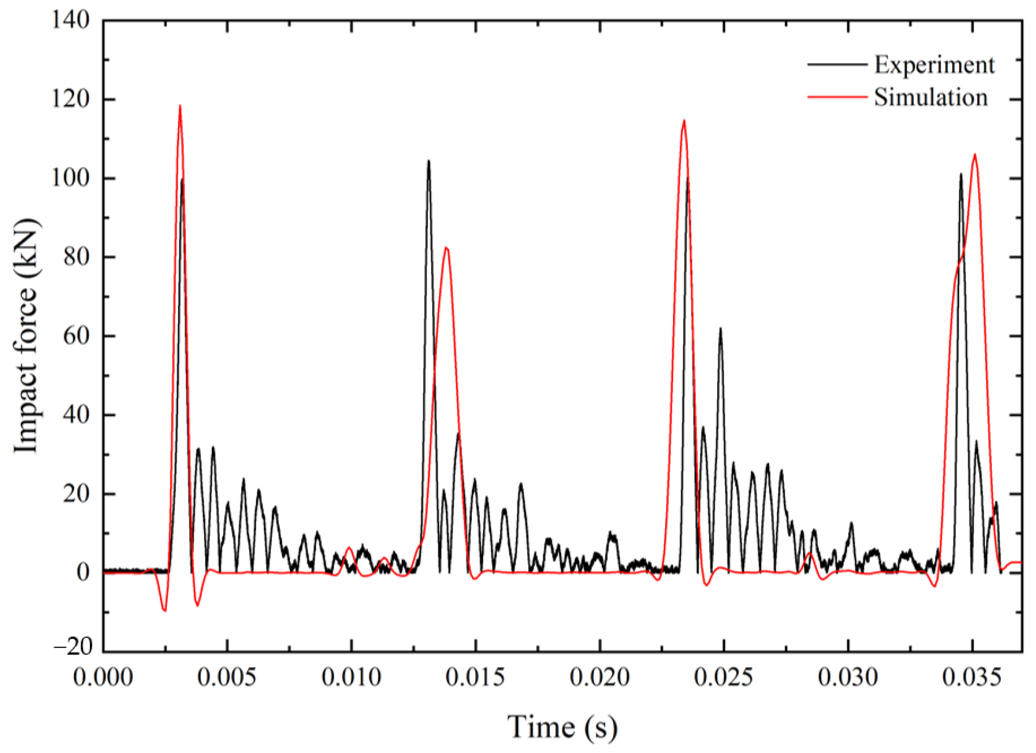
4.2. Comparison of Simulation Results

To verify the accuracy of the finite element model, the axial collision simulation analysis was carried out using the model of test case 3 as an example. The numerical simulation result showed that the peak force during the collision process is 118.47 kN, and the suction energy of the whole collision process is 1889.12 J. Taking the first ring closest to the base as an example, the shear energy absorption process of a single ring was analyzed, and the specific process is shown in Figure 7. When t = 0.0030 s, the impactor impinges on the energy absorption device and the tendency of relative displacement between energy absorption rods and pedestal. When t = 0.0035 s, the contact force between the energy absorption rods and pedestal is greater than the stress limit at the shear rings, and the shear energy absorption process starts, accompanied by the peak force. When t = 0.0040 s, the shear rings closest to the pedestal are sheared off. This process will be repeated for each subsequent shear ring.
Figure 8 shows the F–T curve of the numerical simulation process. From comparing it with the F–T curve of case 3, the peak force of the load curve, the waveform trend, and the collision energy absorption, the peak force error of the collision process is 11%, and the energy absorption error is 12%. It shows that the numerical simulation results are in good agreement with the experimental results, and the effectiveness and correctness of the established finite element model are verified.

5. Discussion

A total of nine kinds of simulation conditions were analyzed. By comparing the velocity change curve of the impactor in the working process of the energy absorption device under different impact conditions, the impact energy absorption under different shear ring distributions was obtained. By controlling the influence factors such as shear ring thickness, spacing, and impactor velocity, the working state and response characteristics of the energy absorption device were simulated. The simulation results obtained are shown in Table 5. The shear ring thickness and spacing in the table represent the structural size of a single energy absorption rod, and each simulation group has only two energy absorption rods.

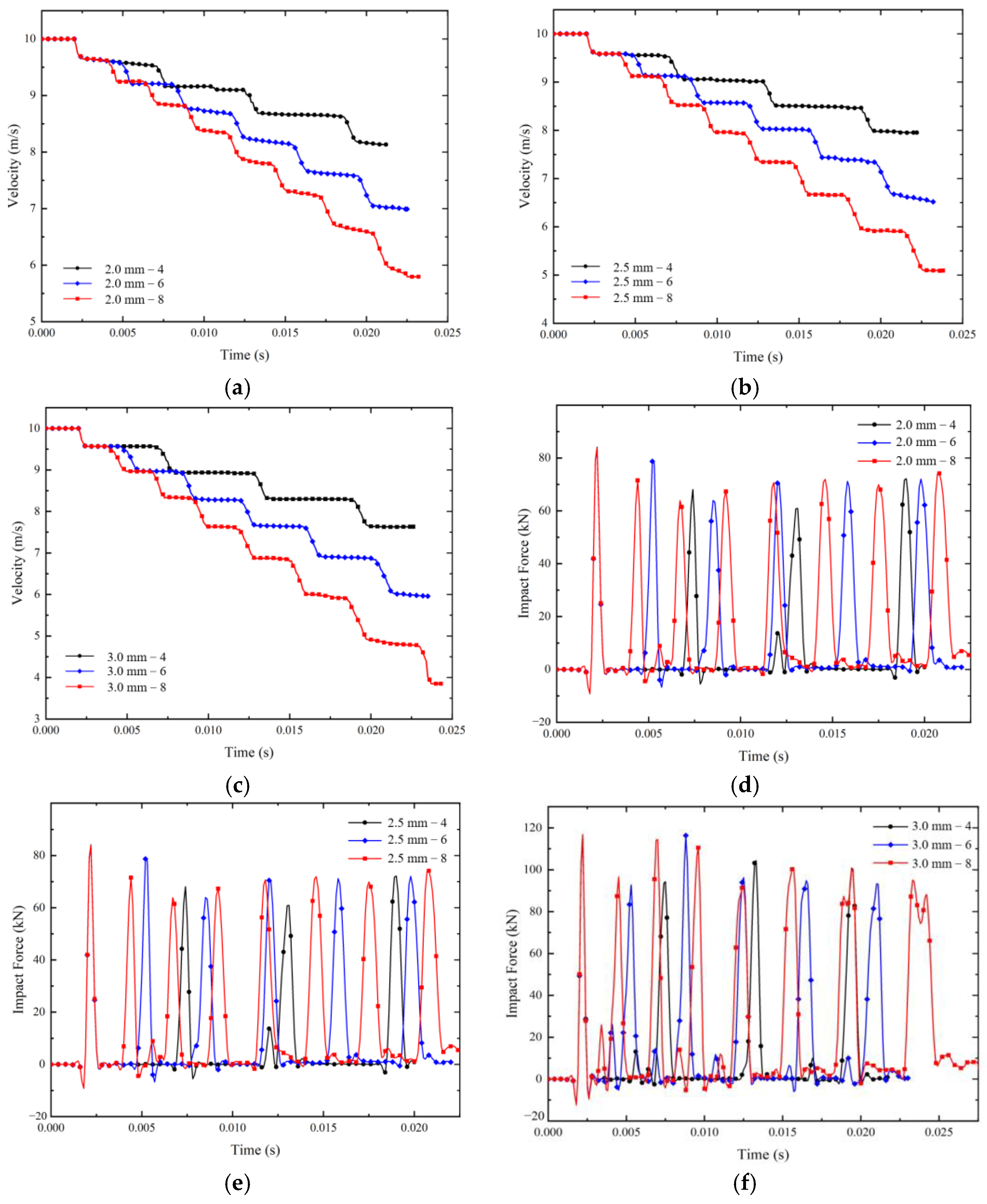
5.1. Influence of Shear Ring Thickness

When the impactor impinges on the energy absorption device with the same shear ring spacing and different shear ring thickness at a speed of 10 m/s, the changes in key parameters are shown in Figure 9. Figure 9a–c shows the velocity curve of the impactor with time. Combined with Figure 9h, it can be seen that the thickness of the shear rings is positively correlated with energy absorption. When the thickness increases from 2.0 mm to 2.5 mm, the energy absorption of the device rises slowly. When the thickness increases from 2.5 mm to 3.0 mm, the energy absorption of the device obviously rises. Figure 9d–f shows the change curve of the impact force in the energy absorption process over time. Combined with Figure 9g, it can be seen that the thickness of the shear rings and the peak force show a linear trend.

5.2. Influence of Shear Ring Spacing

When the impactor impinges on the energy absorption device with the same shear ring thickness and different shear ring spacing at a speed of 10 m/s, the changes in key parameters are shown in Figure 10. Among them, the number of shear rings is inversely proportional to the spacing. Figure 10a–c shows the velocity curve of the impactor with time. Combined with Figure 10h, it can be seen that there is a linear trend between the number of shear rings and the energy absorption. The slope of this linear relationship is different for different shear ring thicknesses. Figure 10d–f shows the change curve of the impact force in the energy absorption process over time. Combined with Figure 10g, it can be seen that there is no obvious correlation between the number of shear rings and the peak force.
The responses of the energy absorption device based on CSR under nine working conditions are analyzed and compared. The energy absorption characteristics of the shear rings are summarized as follows:
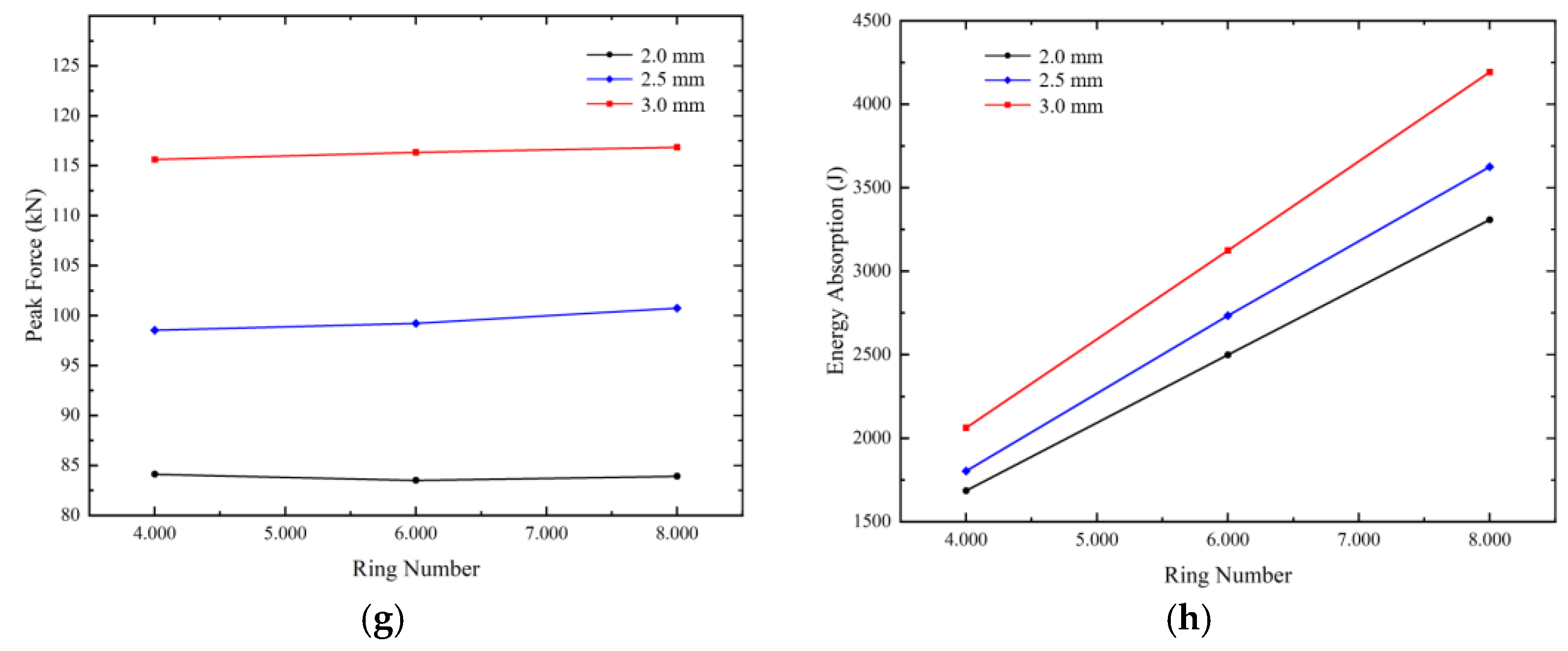
  • Impact energy absorption characteristics of shear rings: By analyzing and comparing the impact energy absorption characteristics of shear rings under nine working conditions, it can be seen that increasing the thickness of shear rings is obviously better than reducing the spacing of shear rings to improve the energy absorption of the device. Because with the reduction of the spacing of shear rings, the energy absorption of the device increases linearly, and with the increase in shear ring thickness, the upward trend of energy absorption of the device is more obvious. Moreover, reducing the spacing of shear rings not only increases the processing procedure but also the quality of the energy absorption rods is greater than that of increasing the thickness, which is not conducive to the lightweight of the energy absorption device.
  • Characteristics of the peak force in the energy absorption process of shear rings impact: The failure of each shear ring in the energy absorption process is accompanied by the generation of peak force, but the maximum peak force usually occurs when the first shear ring is destroyed. There is a linear trend between the shear ring thickness and the peak force, but the spacing of the shear rings has little effect on the peak force. Therefore, in the application process of the energy absorption device, the thickness of the shear ring should be determined according to the installation conditions to ensure that the device will not fall off in the process of energy absorption. Then, according to the requirements for energy absorption, the appropriate spacing of shear rings is selected to achieve the purposes of collision mitigation and energy absorption.

6. Conclusions

The current work is mainly focused on an energy absorption device based on CSR. It not only overcomes the disadvantage that traditional energy absorption devices cannot be used in small spaces due to the need to reserve transverse deformation space but also solves the shortcomings of the complex design and poor practicability of CST. Under ideal conditions, it can quickly absorb collision energy and mitigate impact in a very narrow space with no chip generation. The impact energy absorption characteristics of shear rings are analyzed by the combination of a drop hammer test and numerical element simulation in this work.
The conclusions are as follows:
  • Through the analysis of the F–T curve obtained from the drop hammer impact test, it is found that the energy absorption process of shear rings is often accompanied by the generation of peak forces, which plays an important role in determining whether the installation of the device is secure and whether the energy absorption process can be carried out effectively.
  • By comparing the experiment with numerical simulation, the accuracy and rationality of the comprehensive modeling method of an energy absorption device based on CSR are verified. The preliminary study using numerical simulation can save a lot of human and material resources and greatly improve the research’s efficiency.
  • There is an obvious positive correlation between the energy absorption of the device and the number and thickness of shear rings. To be exact, there is a linear trend between the number of shear rings and the energy absorption, and the slope increases with the increase in thickness.
  • The peak force of the shear rings’ impact energy absorption process is positively correlated with the thickness of the shear rings. It occurs when each shear ring fails, and the maximum peak force usually occurs when the first shear ring fails.

Author Contributions

Conceptualization, S.Y. and Y.W.; methodology, S.Y. and C.S.; software, Y.W.; validation, Y.W.; formal analysis, Y.W.; investigation, N.Z.; resources, X.F.; data curation, Y.W.; writing—original draft preparation, Y.W.; writing—review and editing, S.Y., Y.W. and N.Z.; supervision, S.Y. and N.Z. All authors have read and agreed to the published version of the manuscript.

Funding

This research was funded by the National Natural Science Foundation of China (No. 11902369 and 12272414), the Natural Science Foundation of Hunan province (Project No. 2021JJ30786), and the Project of State Key Laboratory of High-Performance Complex Manufacturing, Central South University (Projects No. ZZYJKT2021-08). In addition, this work was supported in part by the High-Performance Computing Center of Central South University.

Institutional Review Board Statement

Not applicable.

Informed Consent Statement

Not applicable.

Data Availability Statement

Data available on request.

Conflicts of Interest

The authors declare no conflict of interest.

References

  1. Scholes, A. Development of Collision Technologies in European Railways. Foreign Roll. Stock. 1998, 1, 23–26. [Google Scholar]
  2. Cheng, L. The Study of Passive-Safety System and Modular Design for Railway Vehicle. Master’s Thesis, Tongji University, Shanghai, China, 2006. [Google Scholar]
  3. Yan, J.; Yao, S.; Xu, P.; Peng, Y.; Shao, H.; Zhao, S. Theoretical prediction and numerical studies of expanding circular tubes as energy absorbers. Int. J. Mech. Sci. 2016, 105, 206–214. [Google Scholar] [CrossRef]
  4. Xilu, Z.; Kong, C.; Yang, Y.; Hagiwara, I. Reversed-Torsion-Type Crush Energy Absorption Structure and Its Inexpensive Partial-Heating Torsion Manufacturing Method Based on Origami Engineering. J. Manuf. Sci. Eng. 2022, 144, 061001. [Google Scholar] [CrossRef]
  5. Li, B.; Lu, Z.; Yan, K.; Lu, S.; Kong, L.; Xu, P. Experimental study of a honeycomb energy-absorbing device for high-speed trains. Proc. Inst. Mech. Eng. Part F J. Rail Rapid Transit 2020, 234, 1170–1183. [Google Scholar] [CrossRef]
  6. Ma, J.; Chai, S.; Chen, Y. Geometric design, deformation mode, and energy absorption of patterned thin-walled structures. Mech. Mater. 2022, 168, 104269. [Google Scholar] [CrossRef]
  7. San, H.N.; Lu, G. Thin-walled corrugated structures: A review of crashworthiness designs and energy absorption characteristics. Thin-Walled Struct. 2020, 157, 106995. [Google Scholar]
  8. Duan, Y.; Zhang, T.; Zhou, J.; Xiao, H.; Chen, X.; Al Teneiji, M.; Guan, Z.W.; Cantwell, W.J. Energy-absorbing characteristics of hollow-cylindrical hierarchical honeycomb composite tubes inspired a beetle forewing. Compos. Struct. 2021, 278, 114637. [Google Scholar] [CrossRef]
  9. Zhai, J.; Zhang, D.; Li, M.; Cui, C.; Cai, J. Out-of-plane energy absorption and crush behavior of origami honeycomb. Thin-Walled Struct. 2022, 181, 109966. [Google Scholar] [CrossRef]
  10. Baroutaji, A.; Sajjia, M.; Olabi, A.G. On the crashworthiness performance of thin-walled energy absorbers: Recent advances and future developments. Thin-Walled Struct. 2017, 118, 137–163. [Google Scholar] [CrossRef] [Green Version]
  11. Li, Z. Study on Energy Absorption Characteristics and Crashworthiness Optimization of Thin-Walled Structures. Ph.D. Thesis, South China University of Technology, Guangzhou, China, 2019. [Google Scholar]
  12. Reddy, S.; Abbasi, M.; Fard, M. Multi-cornered thin-walled sheet metal members for enhanced crashworthiness and occupant protection. Thin-Walled Struct. 2015, 94, 56–66. [Google Scholar] [CrossRef]
  13. Li, G.; Zhang, Z.; Sun, G.; Huang, X.; Li, Q. Comparison of functionally-graded structures under multiple loading angles. Thin-Walled Struct. 2015, 94, 334–347. [Google Scholar] [CrossRef]
  14. Sun, G.; Huo, X.; Wang, H.; Hazell, P.J.; Li, Q. On the structural parameters of honeycomb-core sandwich panels against low-velocity impact. Compos. Part B Eng. 2021, 216, 108881. [Google Scholar] [CrossRef]
  15. Mousanezhad, D.; Ghosh, R.; Ajdari, A.; Hamouda, A.M.S.; Nayeb-Hashemi, H.; Vaziri, A. Impact resistance and energy absorption of regular and functionally graded hexagonal honeycombs with cell wall material strain hardening. Int. J. Mech. Sci. 2014, 89, 413–422. [Google Scholar] [CrossRef]
  16. Yao, S.J.; Zhang, D.; Lu, F.Y.; Li, X.C. Experimental and numerical studies on the failure modes of steel cabin structure subjected to internal blast loading. Int. J. Impact Eng. 2017, 110, 279–287. [Google Scholar] [CrossRef]
  17. Yao, S.J.; Zhang, D.; Lu, Z.J.; Lin, Y.L.; Lu, F.Y. Experimental and numerical investigation on the dynamic response of steel chamber under internal blast. Eng. Struct. 2018, 168, 877–888. [Google Scholar] [CrossRef]
  18. Zhao, N.; Yao, S.J.; Zhang, D.; Lu, F.Y.; Sun, C.M. Experimental and numerical studies on the dynamic response of stiffened plates under confined blast loads. Thin-Walled Struct. 2020, 154, 106839. [Google Scholar] [CrossRef]
  19. Song, J.; Chen, Y.; Lu, G. Axial crushing of thin-walled structures with origami patterns. Thin-Walled Struct. 2012, 54, 65–71. [Google Scholar] [CrossRef]
  20. Wang, Y.; Xiao, L.; Jiang, C.; Jia, Y.; Yang, G.; Li, M.; Tang, X.; Chen, D. Axial Loading Behaviour of Self-Compacting Concrete-Filled Thin-Walled Steel Tubular Stub Columns. Adv. Civ. Eng. 2021, 2021, 8861340. [Google Scholar] [CrossRef]
  21. Liu, S.; Liu, Y.; Zhang, Y.; Li, Z. Low speed impact response of carbon fiber-aluminum foam sandwich panels. Chin. J. High Press. Phys. 2020, 34, 107–116. [Google Scholar]
  22. Yu, P.; Liu, Z.; Li, S. Design and energy absorption characteristic analysis of a new bamboo thin-walled circular tube. Chin. J. High Press. Phys. 2021, 35, 104–114. [Google Scholar]
  23. Li, P.; Yang, F.; Bian, Y.; Zhang, S.; Wang, L. Deformation pattern classification and energy absorption optimization of the eccentric body centered cubic lattice structures. Int. J. Mech. Sci. 2021, 212, 106813. [Google Scholar] [CrossRef]
  24. Zhao, M.; Zhang, D.; Liu, F.; Li, Z.; Ma, Z.; Ren, Z. Mechanical and energy absorption characteristics of additively manufactured functionally graded sheet lattice structures with minimal surfaces. Int. J. Mech. Sci. 2020, 167, 105262. [Google Scholar] [CrossRef]
  25. Beik, V.; Fard, M.; Jazar, R. Crashworthiness of tapered thin-walled S-shaped structures. Thin-Walled Struct. 2016, 102, 139–147. [Google Scholar] [CrossRef]
  26. Jung, A.; Lach, E.; Diebels, S. New hybrid foam materials for impact protection. Int. J. Impact Eng. 2014, 64, 30–38. [Google Scholar] [CrossRef]
  27. Chang, N. Simulation of Energy-Absorbing Process in Metal-Cutting Way. Master’s Thesis, Central South University, Shanghai, China, 2006. [Google Scholar]
  28. Chang, N.; Liu, G. Simulation for energy-absorbing process of railway vehicle in metal-cutting way. J. Cent. South Univ. (Sci. Technol.) 2010, 41, 2444–2450. [Google Scholar]
  29. Wang, J.; Lu, Z.; Zhong, M.; Wang, T.; Sun, C.; Li, H. Coupled thermal–structural analysis and multi-objective optimization of a cutting-type energy-absorbing structure for subway vehicles. Thin-Walled Struct. 2019, 141, 360–373. [Google Scholar] [CrossRef]
  30. Lei, Z.; Luo, Y. The Cutting Thread Shear Vehicle Collision Energy Absorption Device. CN Patent CN1460616, 10 December 2003. [Google Scholar]
  31. Luo, Y.; Lei, Z. Research on the application of the cutting thread shear vehicle collision energy absorption device. Highw. Automot. Appl. 2007, 4, 4–6. [Google Scholar]
  32. Li, N. Research on the Self-Loosening Behavior of Three Kinds of Threaded Connection Structures under Shear Excitation. Master’s Thesis, Southwest Jiaotong University, Chengdu, China, 2014. [Google Scholar]
  33. Han, J. Research on Threaded Shear Energy Absorbing Component of Punch-Proof Hydraulic Support Column. Master’s Thesis, Liaoning Technical University, Liaoning, China, 2019. [Google Scholar]
  34. Tang, N. Optimum Design of the Equipment of Car Crashes Using Thread Cutting. Master’s Thesis, Changsha University of Science & Technology, Changsha, China, 2010. [Google Scholar]
  35. Zhu, H. The Design of Cutting the Screw Thread’s Swift Propulsion System. Master’s Thesis, Changsha University of Science & Technology, Changsha, China, 2010. [Google Scholar]
  36. Li, J.; Lei, Z.; Zhu, H. Development of parts model for cutting the screw thread system. J. Graph. 2011, 32, 31–36. [Google Scholar]
  37. Wei, S.; Lei, Z.; Du, Q. Mesh size optimization on analysis of energy-absorbing thread shearing process in car collision. J. Mech. Strength 2010, 32, 859–864. [Google Scholar]
  38. Mamalis, A.G.; Robinson, M.; Manolakos, D.E.; Demosthenous, G.A.; Ioannidis, M.B.; Carruthers, J. Crashworthy capability of composite material structures. Compos. Struct. 1997, 371, 109–134. [Google Scholar] [CrossRef]
  39. Signorini, C.; Sola, A.; Malchiodi, B.; Nobili, A.; Gatto, A. Failure mechanism of silica coated polypropylene fibres for Fibre Reinforced Concrete (FRC). Constr. Build. Mater. 2020, 236, 117549. [Google Scholar] [CrossRef]
  40. Jing, Y.Y.; Barton, D.C. The response of square cross-section tubes under lateral impact loading. Int. J. Crashworthiness 1998, 33, 359–378. [Google Scholar] [CrossRef]
  41. Lu, G. A study of the crushing of tubes by two indenters. Int. J. Mech. Sci. 1993, 35, 267–278. [Google Scholar] [CrossRef]
  42. Wang, Z.; Li, M.; Han, Q.; Yun, X.; Zhou, K.; Gardner, L.; Mazzolani, F.M. Structural fire behaviour of aluminium alloy structures: Review and outlook. Eng. Struct. 2022, 268, 114746. [Google Scholar] [CrossRef]
  43. Zhao, L. Research status and development trend of ultra high strength aluminum alloy. J. Ordnance Equip. Eng. 2011, 32, 147–150. [Google Scholar]
  44. Li, H.; Chen, S.; Ma, Y.; Chen, D.; Xu, Y.; Zhang, S.; Song, H. Forming of complex disk component with 2B06 aluminium alloy under impact hydroforming. J. Ordnance Equip. Eng. 2022, 43, 1–7. [Google Scholar]
  45. Senthil, K.; Iqbal, M.A.; Chandel, P.S.; Gupta, N.K. Study of the constitutive behavior of 7075-T651 aluminum alloy. Int. J. Impact Eng. 2017, 108, 171–190. [Google Scholar] [CrossRef]
Figure 1. The model of energy absorption device based on CST. (a) Energy absorption device; (b) energy absorption rod.
Applsci 13 01860 g001
Figure 2. Working principle concept diagram.
Applsci 13 01860 g002
Figure 3. Test apparatus diagram. (a) drop hammer impact test setup; (b) pedestal and bolts.
Applsci 13 01860 g003
Figure 4. Shear energy absorption process diagram.
Applsci 13 01860 g004
Figure 5. Impact force–time curve and post-impact rods. (a) case 1; (b) case 2; (c) case 3.
Applsci 13 01860 g005aApplsci 13 01860 g005b
Figure 6. Finite element model of the CSR system.
Applsci 13 01860 g006
Figure 7. Shear ring energy absorption process. (a) t = 0 s; (b) t = 0.0020 s; (c) t = 0.0022 s; (d) t = 0.0026 s.
Applsci 13 01860 g007
Figure 8. Collision energy absorption test results and simulation comparison.
Applsci 13 01860 g008
Figure 9. Impact process key parameter curve. (a) Velocity—51.67 mm/4; (b) velocity—31.00 mm/6; (c) velocity—22.14 mm/8; (d) impact force—51.67 mm/4; (e) impact force—31.00 mm/6; (f) impact force—22.14 mm/8; (g) summary—peak force; (h) summary—energy absorption.
Applsci 13 01860 g009
Figure 10. Impact process key parameter curve. (a) Velocity—51.67 mm/4; (b) velocity—31.00 mm/6; (c) velocity—22.14 mm/8; (d) impact force—51.67 mm/4; (e) impact force—31.00 mm/6; (f) impact force—22.14 mm/8; (g) summary—peak force; (h) summary—energy absorption.
Applsci 13 01860 g010aApplsci 13 01860 g010b
Table 1. Summary of test conditions.
CaseMass (kg)Height (m)Number of RodsNumber of Shear RingsVelocity (m/s)Energy (J)
1982.461216.942362.58
213870.603213.438155.56
3981.56245.531402.42
Table 2. Chemical composition of 7075 aluminum ally.
Al.ZnMgCuCrSiFeTiMn
Bal.5.800.041.400.010.070.180.030.05
Table 3. Mechanical properties of 7075 aluminum ally.
ρ   (kg/m3) E (GPa) ν σ b (MPa)
281071.70.33460
Table 4. Mechanical properties of 45 # steel.
ρ   (kg/m3) E (GPa) ν
78502000.30
Table 5. Summary of finite element simulation results.
CaseVelocity (m/s)Ring Thick (mm)Spacing (mm)/Number of Shear RingsEnergy Absorption (J)Impact Force (kN)
110.02.051.67/41685.1184.12
210.02.031.00/62499.0283.50
310.02.022.14/83307.9983.91
410.02.551.67/41803.0898.53
510.02.531.00/62733.1099.21
610.02.522.14/83625.51100.74
710.03.051.67/42062.31115.61
810.03.031.00/63124.22116.34
910.03.022.14/84192.44116.84
Disclaimer/Publisher’s Note: The statements, opinions and data contained in all publications are solely those of the individual author(s) and contributor(s) and not of MDPI and/or the editor(s). MDPI and/or the editor(s) disclaim responsibility for any injury to people or property resulting from any ideas, methods, instructions or products referred to in the content.

