Article

Diffusion Model of Cement Slurry in Porous Media Considering Porosity Variation and Percolation Effect

1
Key Laboratory of Road and Bridge Detection and Maintenance Technology Research of Zhejiang Province, Hangzhou 310012, China
2
Transportation Development Center of Jingning She Autonomous County, Lishui 323500, China
3
Architectural Engineering Institute, Huanghuai University, Zhumadian 463000, China
4
School of Water Conservancy Science and Engineering, Zhengzhou University, Zhengzhou 450000, China
5
Nottingham Transportation Engineering Centre, University of Nottingham, Nottingham NG7 2RD, UK
*
Authors to whom correspondence should be addressed.
Appl. Sci. 2023, 13(3), 1919; https://doi.org/10.3390/app13031919
Submission received: 13 November 2022 / Revised: 10 January 2023 / Accepted: 17 January 2023 / Published: 2 February 2023
(This article belongs to the Topic Pipeline and Underground Space Technology)

Abstract

:
The porosity of porous media is a key factor affecting cement slurry diffusion. In this paper, a theoretical model of cement slurry diffusion in porous media considering the variation of porosity is proposed. The model is validated through comparison with the experimental results in the literature. The influence of injection parameters (i.e., the water–cement ratio and the pore fractal dimension) on the porosity and strength of porous media is analyzed. The results indicate that: under the same pore fractal dimension, the porosity of the specimen increases gradually with the increase in diffusion distance, and the rate increases rapidly in the later stage. However, when the fractal dimension of porosity increases to 2.1, the porosity of the consolidated body after grouting does not change with the diffusion distance. The water–cement ratio also affects the porosity of the sample. At a distance below 1.0 m, the sample porosity is larger at a larger water–cement ratio of 1.5. When the distance is more than 1.0 m, the smaller the porosity decreases with increasing water–cement ratios. With the increase in distance, the compressive strength of the specimen first decreases slowly, and then rapidly from 90 kPa to 0 kPa. This is further verified by the pore variation law obtained by SEM. The model is applied to selecting grouting parameter design in road maintenance. The pavement deflection after grouting is effectively reduced, verifying the theoretical model’s applicability.

1. Introduction

Under the action of long-term load and environment, loosening is more likely to occur at the semi-rigid base of the pavement, leading to insufficient bearing capacity and decreased service life [1,2]. Conventional restoration methods require excavation and re-placement of highways, which causes resource waste and impacts the environment. Although the micro-surface and thin cladding can extend pavement service life [3], it is difficult to cure deep semi-rigid base defects. Grouting is a convenient road maintenance method [4,5]. In the process of underground excavation, grouting can also reinforce the soil to prevent collapse. Cement and chemical slurry are two kinds of grouting materials that are widely used [6,7,8]. Cement-based grouting materials have the characteristics of low cost and less impact on the environment, thus facilitating more extensive use [9,10,11]. The hydration and microcosmic properties of cement-based materials have been extensively studied [12,13,14]. However, the percolation effect on cement in the grouting process has not been fully considered, which will lead cement particles to be blocked in the pores of grouted media during diffusion. Then, the cement particles will gather near the grouting mouth. Consequently, the porosity of the injected medium near the grouting mouth is reduced, blocking the pore channel of the injected medium. Thus, it is difficult for cement particles to continue to diffuse, affecting the repair effect of grouting [15,16]. More importantly, the performance of the consolidated body after grouting is closely related to the concentration of injected cement and the diffusion characteristics of cement particles in the medium. The strength of the consolidated body increases with the cement particles, indicating that the filtration effect will affect the repair effect of grouting [17,18].
The influence of the filtration effect on the diffusion distance and grouting pressure of different types of cement grout and porous media has been studied. Li [15] established a one-dimensional slurry percolation diffusion numerical model by including the percolation effect and revealed the influence mechanism of the percolation effect on the grouting effect. Their findings provided a theoretical basis for improving the grouting method. Bennacer [16] found that the uneven precipitation of suspended particles in water-saturated porous media was affected by the size and distribution of cement particles. Li [19] developed a grouting diffusion model considering the temporal variation in viscosity and the percolation effect and used the difference method to solve the theoretical model. Yoon [20] established a bentonite-slurry diffusion distance calculation model considering the slurry percolation effect. Axelsson [21] conducted experiments to determine the mechanism responsible for the termination of penetration and diffusion of cement grout. Du [22] established diffusion models of single-hole grouting and multi-hole grouting considering the percolation effect. It was found that the percolation effect can cause the cement particles to gather at shorter distances. However, there are almost no cement particles at the edge of the diffusion distance. Ye [23] established a grout diffusion model for grouting behind shield tunnel walls considering the percolation effect, and the results showed that the percolation effect significantly affects the grouting pressure. Then, the cylindrical and spherical infiltration diffusion model of power-law fluid grouts was developed by Ye [24]. Du [25] verified that the percolation effect would reduce the diffusion distance of slurry through experiments. Meanwhile, the percolation effect can also restrict the diffusion of cement, affecting the distribution of cement particles in the pores of the medium. Zheng [26] proposed a numerical model for grouting penetration in porous media considering the filtration effect in order to study the grouting motion law. However, during grouting, the porosity of the injected medium changes dynamically. If the porosity is regarded as constant, the error of diffusion distance and diffusion effect will be affected. Nevertheless, the above research does not fully consider real-time porosity changes.
Since Mandelbrot published his famous paper on fractal geometry1967, the fractal theory has been applied in various fields [27]. For example, it can be applied to the vulnerability assessment of water network disasters, damage diagnosis for offshore wind turbine foundations [28,29], prediction of the permeability and strength of multi-scale pores and fractures in different media [30,31], evaluation of the landform, surface roughness, and pore and fractal structure characteristics of porous media [32,33,34,35,36,37,38,39,40,41,42]. Therefore, fractal theory can be used to characterize the distribution law of pore channel diameter and a zigzag degree in porous media [43,44]. However, considering the influence of the percolation effect, there are few studies on applying fractal theory to characterize the dynamic variation in porosity when grout diffuses in the medium [45]. Moreover, the percolation effect will cause the slurry to spread to a certain area of the porous medium. However, due to the low concentration of the slurry, the strength of the area cannot reach the design strength. This is because the diffusion range of cement particles will affect the porosity of the medium after injection, thus changing the medium strength. Bohloli [46] studied the percolation stability and strength of cement slurries at various temperatures. Du [25] studied the changing law of the compressive strength of grout at different diffusion distances and found that the strength of the consolidated body decreased with the increase in grouting distance. Wang [47] analyzed the mechanical properties of the consolidated body at different distances from the grouting pipe through model tests and found that the mechanical properties of the samples obtained at different locations of the consolidated body were different. Nevertheless, the influence of the percolation effect on the strength of the medium after grouting has not been quantitatively studied.
During grouting construction, the diffusion effect of grout in the medium and the distribution characteristics of particles are the key factors that affect the effect of grouting reinforcement. Consequently, understanding the spatial distribution of cement slurry injected into porous media is beneficial to reveal the repair and reinforcement effect of cement grouting. Therefore, considering the influence of the percolation effect, the fractal theory is introduced into the diffusion model of cement grouting. This paper focuses on the porosity variation in the sand medium during grouting and develops a porosity variation model for the injected porous medium. Experimental results in the literature were selected to verify the influence of injection parameters such as cement content, pore characteristics and spatial distribution characteristics of cement strength on the grouting effect in the theoretical model. The findings of this study can provide a guide for the design of injection parameters of cement grouting and help to overcome the shortcomings of empirical grouting parameter selection.

2. Porosity Analysis of Injected Porous Media

Cement-based materials are usually treated as Bingham fluids, and their flow rate through a single pore channel is
q ( λ ) = π λ 3 + D T 128 μ L D t 1 D T d p d L τ 0 π λ 3 32 μ
where τ 0 is yield stress, μ is the viscosity, Df is the fractal dimension of the channel, and Dt is the tortuous fractal dimension of the channel.
Then, the flow rate per unit cross-section can be expressed as,
Q ( λ ) = λ min λ max q ( λ ) d N ( λ ) = λ min λ max ( π λ 3 + D T 128 μ L D T 1 D T d p d L τ 0 π λ 3 32 μ ) × D f λ max D f λ ( D f + 1 ) d λ = π λ max 3 + D r D f d p 128 μ L D τ 1 D T ( 3 + D T D f ) d L [ 1 ( λ min λ max ) 3 + D T D f ] = π τ 0 D f 32 μ ( 3 D f ) λ max 3 [ 1 ( λ min λ max ) 3 D f ]
where the diameters of this series of pore channels are (λmin, λmax).
The number of tortuous channels in a porous medium can be expressed as in [43,44]:
  d N ( λ ) = D f λ max D f λ D f + 1 d λ ,
The actual length Lt of the curved channel can be expressed as
  d L t = λ 1 D T L D T 1 D T d L ,
where λ is the diameter of the curved channel, and Lt and L0 are the actual and representative lengths of the channel, respectively.
In an element, the pore area AP of all pore channels on a certain cross-section can be expressed as
  A P = λ min λ max 1 4 π λ 2 d N ( λ ) = λ min λ max 1 4 π λ 2 D f λ max D f λ - D f + 1 d λ = π D f 4 ( 2 D f ) λ max 2 [ 1 ( λ min λ max ) 2 D f ]
Assuming that the dynamic porosity of the injected medium is φ, then the total area A of a certain cross-section in the unit can be expressed as
A = A P φ
The average flow rate of slurry in porous medium is,
v = Q ( λ ) A = λ max 1 + D T ϕ ( 2 D f ) d p 32 μ L D f 1 D T ( 3 + D T D f ) d L × [ 1 ( λ min λ max ) 3 + D T D f ] / [ 1 ( λ min λ max ) 2 D f ] λ max τ 0 ϕ ( 2 D f ) 8 μ ( 3 D f ) [ 1 ( λ min λ max ) 3 D f ] / [ 1 ( λ min λ max ) 2 D f ]
From Equation (6), the initial porosity of injected media can be expressed as,
  φ 0 = A P 0 A = π D f 4 ( 2 D f ) λ max 2 [ 1 ( λ min λ max ) 2 D f ] / A
Considering the percolation effect of cement slurry, the dynamic porosity of the injected medium can be expressed as,
  φ = A p t A = π D f 4 ( 2 D f ) ( λ max Δ λ ) 2 [ 1 ( λ min λ max Δ λ ) 2 D f ] / A
where Ap0 and Apt are the pore area of the injected medium on a certain cross-section before and after percolation, respectively; ∆λ is the reduction in the diameter of the pore channels.
Dividing Equation (9) by Equation (8), the real-time porosity of porous media can be further expressed as
φ = ( 1 Δ λ λ max ) 2 [ 1 ( λ min λ max Δ λ ) 2 D f ] / [ 1 ( λ min λ max ) 2 D f ] φ 0
According to the references [48,49], Equation (10) can be obtained as,
Δ λ = λ max λ max 1 β σ φ 0 ( 0 σ < φ 0 β )
where β is the expansion coefficient of cement slurry particles, generally ranging between 2–3; σ is the volume of cement slurry particles remaining in the porous medium in a unit volume.
Therefore,
σ ( L , t ) = k c 0 r 0 2 exp [ k υ 0 r 0 ] ( λ max 1 D T L D T ) 2 exp [ k υ 0 λ max 1 D T L D T ] ( t λ max 1 D T L D T υ 0 ) ( 0 σ < β φ 0 )
where k is the ratio of the volume of cement particles to the total volume of cement slurry; r0 is the radius of the injection hole; v0 is the initial diffusion velocity of slurry, and c0 is the initial cement content.
From Equations (10)–(13), the dynamic porosity of the injected medium can be further expressed as
φ = { φ 0 ( σ = 0 ) [ 1 β σ φ 0 ( λ min λ max ) 2 D f ( 1 β σ φ 0 ) 0.5 D f ] [ 1 ( λ min λ max ) 2 D f ] φ 0 ( 0 < σ < β φ 0 )
The model derived in this paper is only applicable to the use of cement-based materials in the field of grouting in porous media. Because only when the cement particles are diffused in the porous media of different apertures, the cement particles will be captured by the pores of the media and blocked, thus the percolation effect will occur, further leading to changes in the porosity of the media. The model derived in this paper cannot be applied in the field of rock fissure sealing, water gushing during tunnel excavation, and dam leakage channels.

3. Numerical Analysis

This study aims to reveal the spatiotemporal variation in the porosity of porous media from a microscopic perspective. Therefore, the model derived in this paper was numerically analyzed. The influence of grouting parameters (Table 1), such as the water–cement ratio and the fractal dimension of particle mass on the temporal and spatial variation mechanism of grout diffusion in porous media, was studied under the constant pressure condition. In order to verify the applicability of the theoretical model, the design of test parameters and results was based on the study by Du [45]. Therefore, the numerical analysis results were compared with the experimental results in the reference.
Figure 1 depicts the relationship between porous media porosity and cement particle diffusion distance at each test point of the model and experimental results [45] under different fractal dimensions of the pore. The results show that: the porosity of the media in the test section is close to that at the injection port in the sand with a fractal dimension (Dm) of particle mass of 2.1, and the porosity is low and generally unchanged. When it diffuses to 1.05 m, the porosity slowly increases. When it reaches 1.35 m, the porosity rapidly increases. At a Dm of 1.5, the porosity increases slowly with the increase in the distance from the injection port. Comparing the predicted and measured relationship between the porosity and the diffusion distance of the porous medium shows that the experimental results are consistent with the model prediction. However, there is a slight difference in quantity. This is because during grouting diffusion, massive cement slurry particles are gathered on the unit section close to the injection port, resulting in a high retention rate of cement particles at the injection port. Thus, it is easy to cause a rapid decline in porosity and even block pores. When the porosity of the injected medium approach to the injection port is reduced to the threshold value or the pore channel is completely blocked, the retention rate of cement particles increases gradually near the injection port. The medium will be blocked. Then, close to the injection source, the retention rate of cement particles rapidly falls. Additionally, the porosity of the porous medium approach to the injection port is large. Thus, it is difficult for cement particles to stay in the porous medium, and the blockage will not occur immediately. As a result, the diffusion distance of cement slurry is relatively large for a porous medium with a low Dm. In a porous medium, cement particles are larger and more evenly dispersed. The overall trend of the model and the experiment is the same. Due to the accuracy of the experiment operation, the difference lies within the allowable error range.
Figure 2 shows the variation law of porous medium porosity with distance at each test point and model at different water–cement ratios of the cement slurry. Figure 2 demonstrates that the porosity of each measurement point increases with the increase in slurry diffusion distances. The variation trend of the porosity in a low-porosity medium is relatively slow. This is because the cement concentration is large at a low water–cement ratio of the slurry. The proportion of cement particles per unit volume is relatively large. The cement particles stay in a certain section of the porous medium instantaneously so that the slurry diffusion stops, and the porosity of each test point increases rapidly with distance. Cement particle retention is mostly concentrated at the grouting port of the porous medium, resulting in less porosity near the grouting port. In addition, considering the experimental errors, the difference between the model and the experiment is also within the error range.
Figure 3 shows the variation law of uniaxial compressive strength and distance of each test point. The top is the microstructure of the cement particles at various distances scanned by a model USA-FEI-Quanta250FEG field emission scanning electron microscope. Figure 3 demonstrates that the compressive strength of slurry and sand consolidation reduces with increasing distances from the injection port. This is mainly because cement particles mainly stay near the grouting port of porous media, resulting in smaller porosity and larger compactness near the grouting port. Meanwhile, more cement particles hydrate and cement, thus increasing the compressive strength of the injected media near the grouting port. At the position away from the grouting port, the cement particles are unable to diffuse due to the percolation effect. The porosity maintains the state before grouting, and thus the strength is unchanged.
From a microstructure perspective (Figure 4), the filling degree is higher at a closer position to the grouting port, and the porosity of the specimen is smaller. Then, the compressive strength is larger. In order to quantitatively prove the influence of cement slurry injection on the microstructure of the injected medium, ImageJ software was used to quantitatively analyze the SEM images of the grout. The binarization and vectorization of SEM images were mainly carried out to calculate the proportion of pore and fissure area in the overall morphology. Figure 5 shows the images after binarization treatment. As shown in Figure 6, quantitative analysis of the microstructure of the consolidated body shows that as the distance between the consolidated body and the grouting port increases, the proportion of pores and cracks in the consolidated body is higher, and the compactness of the consolidated body is lower. This further verifies the accuracy of the above model and experimental results from a microscopic perspective [45]. When the distance exceeds 1.05 m, it is difficult to take out a complete core sample, indicating that the slurry diffusion to the area is less. Thus, the SEM test was not conducted.

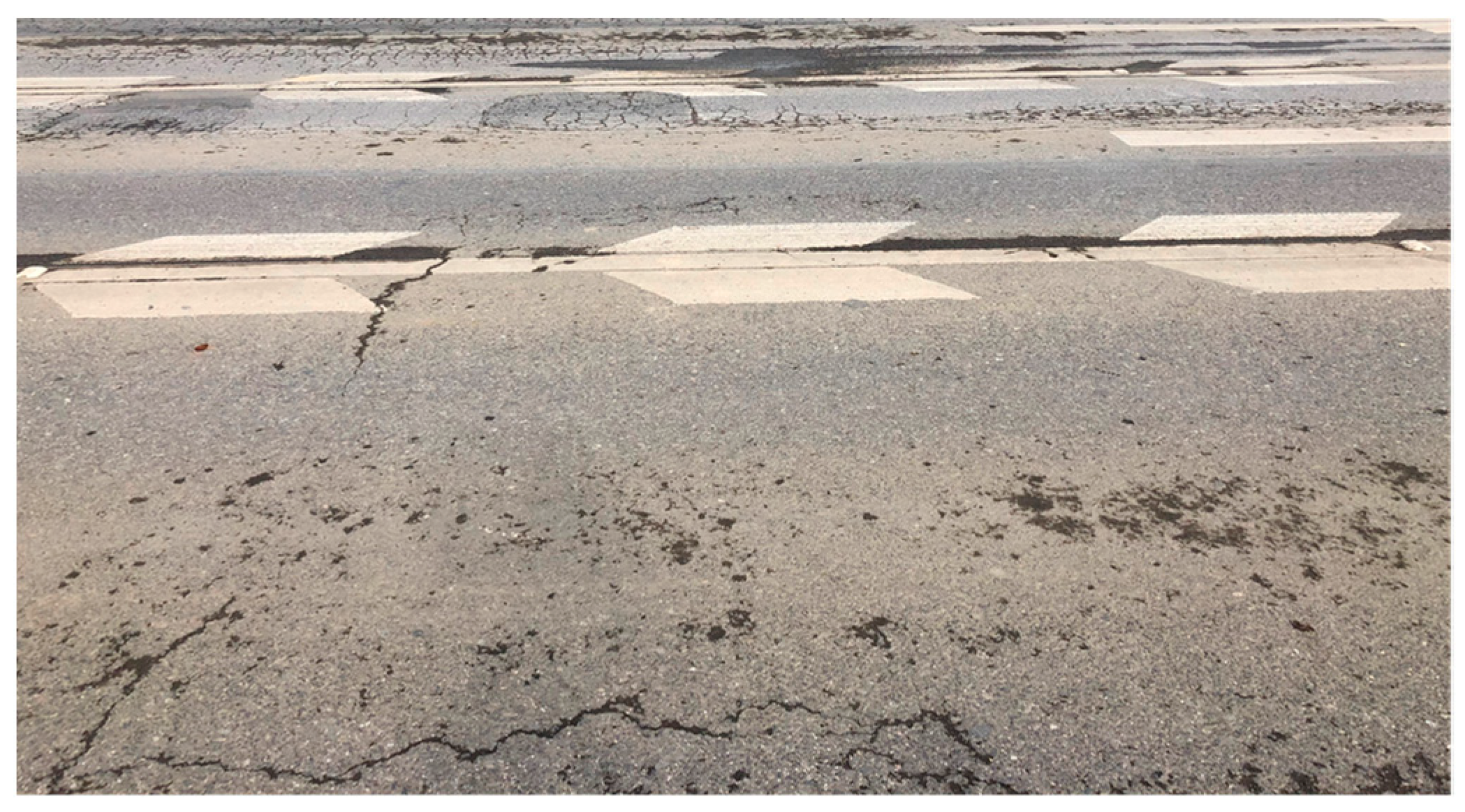
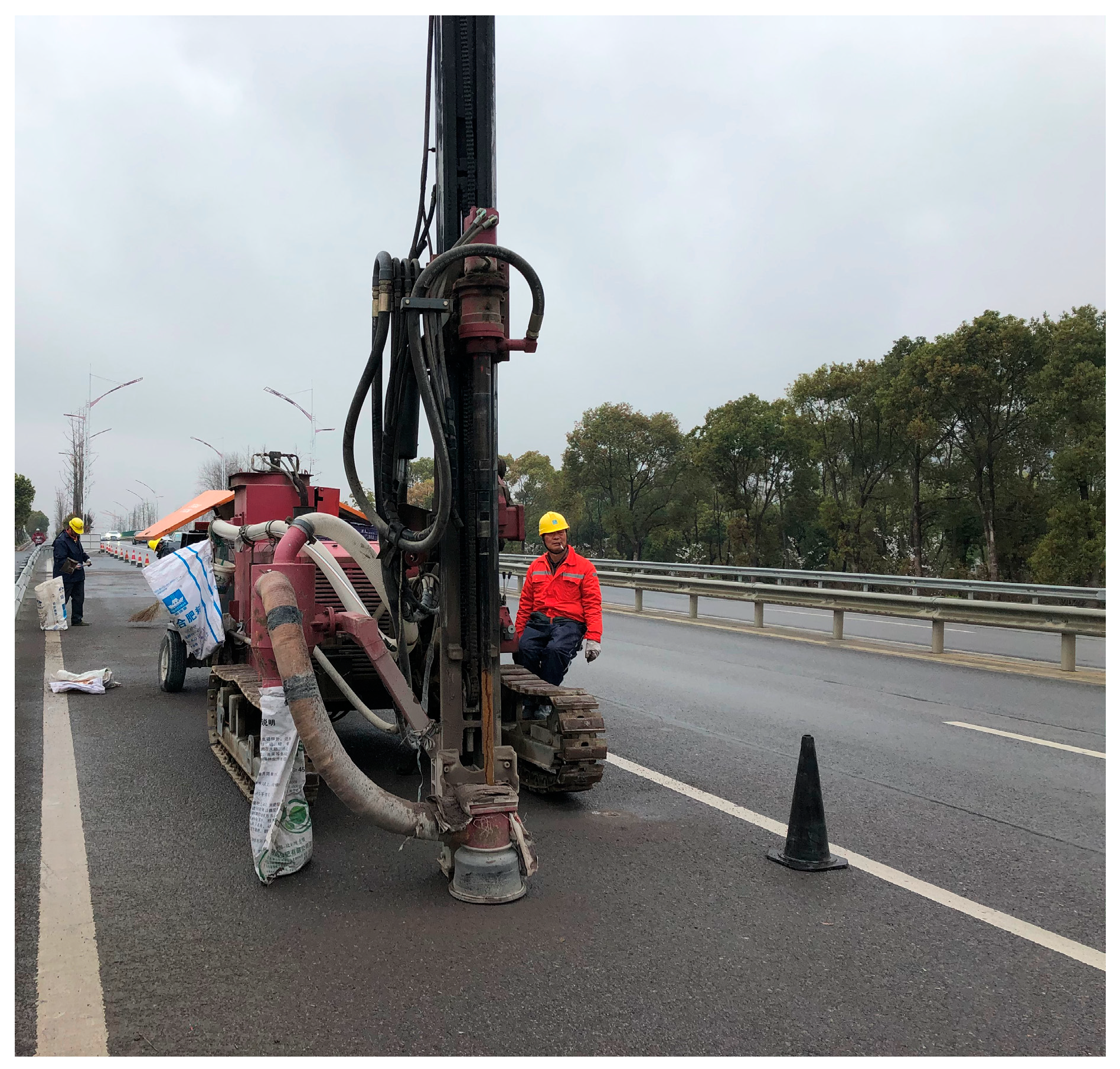
4. Engineering Application

To illustrate the application of the proposed model to pavement maintenance, a typical highway section was adopted for a case study. The highway section was asphalt concrete pavement with a design life of 15 years. The pavement structures from top to bottom included 4 cm medium-grain asphalt concrete, 5 cm coarse-grain asphalt concrete, 7 cm hot mix asphalt crushed stone, 20 cm cement-stabilized crushed stone base and 35 cm lime-stabilized soil. Since the completion of the pavement, the traffic volume has been heavy, and the proportion of overloaded and heavy vehicles has been relatively high. Therefore, under long-term traffic load, serious network cracks appeared on the road surface (Figure 7). After water flowed through the cracks to the base, the hydrodynamic pressure soon softened the fine soil and undermined its strength under traffic load. Thus, this could result in mud pumping from the fine soil. With the gradual deepening of pavement damage, the highway exhibited more serious mud pumping and insufficient bearing capacity. Therefore, it was necessary to use cement grouting technology to repair the damage. The specific process is as follows:
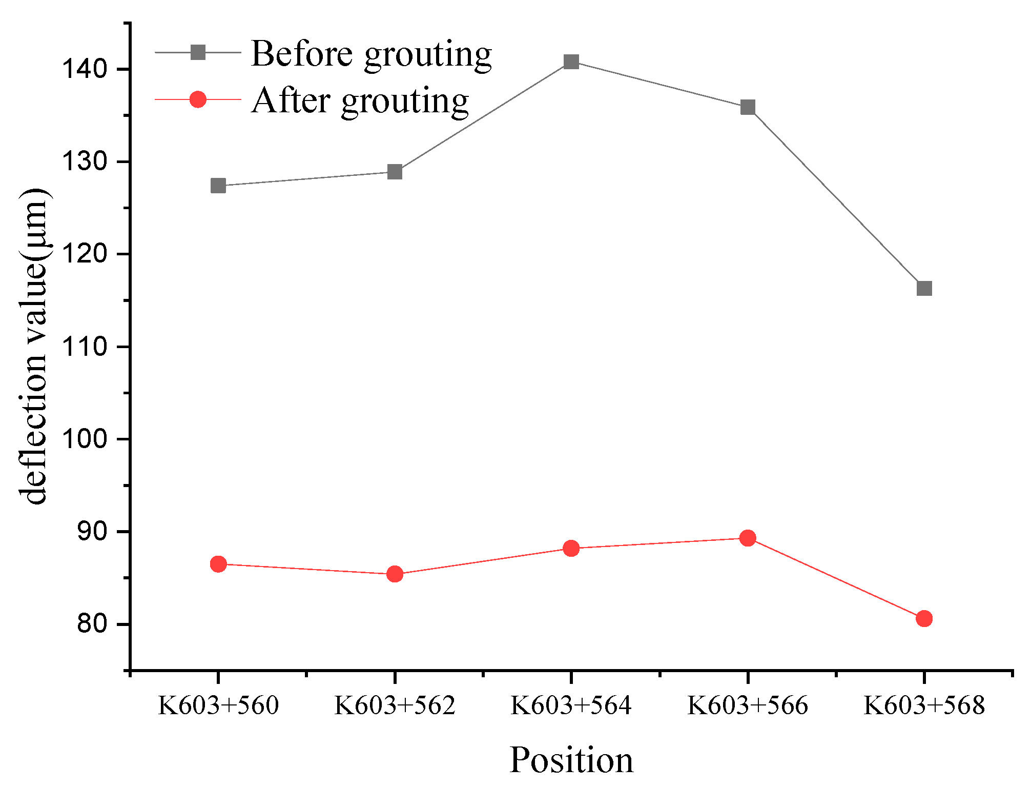
  • FWD was used to test the pavement bearing capacity before grouting, so as to evaluate the degree of pavement damage.
  • The pore structure parameters of this highway section should be quantitatively analyzed by drilling and coring, and corresponding to the parameters in the model.
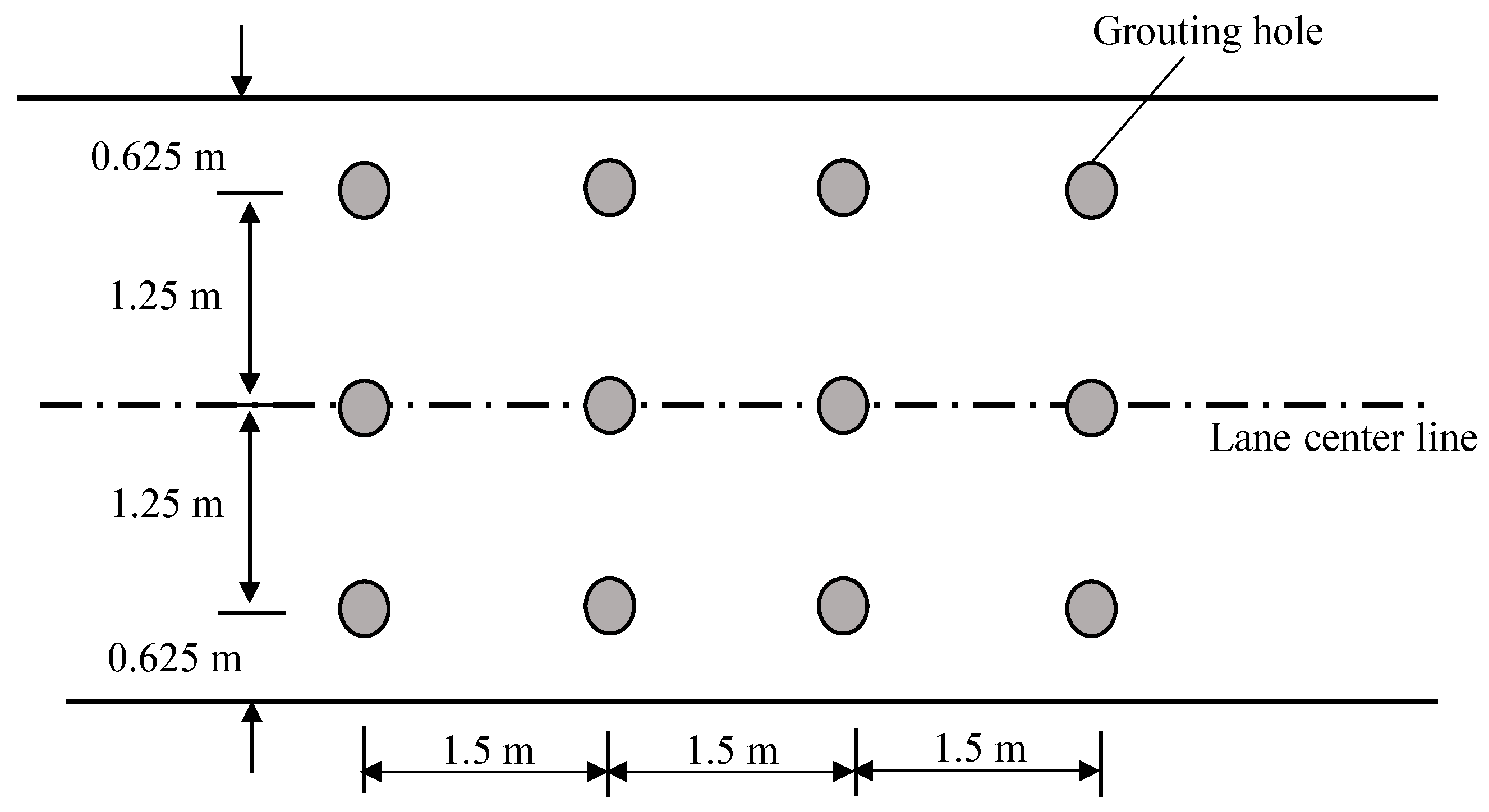
  • According to the model deduced in this paper, the optimum spacing of grouting holes was designed according to the characteristics of the pavement pore structure and cement grout on site.
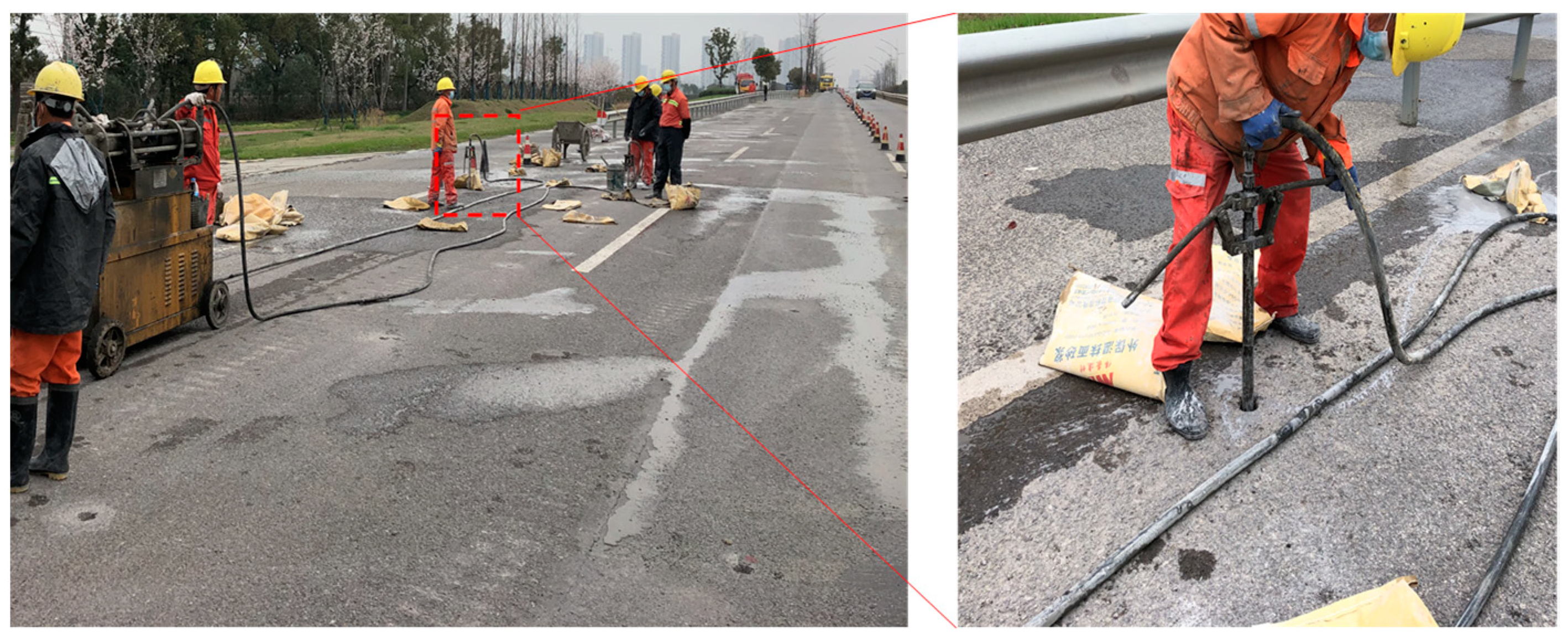
  • An appropriate cement slurry ratio was selected to implement grouting on the pavement.
  • After grouting was completed, the grouting holes were filled with road sealant to prevent water from penetrating the road surface.
  • Fourteen days after grouting, FWD was used to test the pavement bearing capacity after grouting, so as to evaluate the pavement repair effect under the grouting parameters [5,50].
Through an analysis of borehole data, the characteristic structural parameters of the injected medium were determined (φ = 0.52, λmin/λmax = 0.0492, DT = 1.12, Df = 1.69 and Dm = 1.5). The water–cement ratio of the cement grouting material was 1.0. Substituting these parameters into the model, according to the law of Figure 1 and Figure 2, the grouting spacing was set at 1.5 and 1.25 mm in the longitudinal and transverse directions, respectively (Figure 8). The drilling process is shown in Figure 9. The cement grouting process is shown in Figure 10.
Figure 11 shows the deflection changes before and after grouting. The deflection of the pavement was effectively reduced after grouting. This was because the cement material could fill the pores inside the base, reduce the porosity, increase the degree of compaction, produce cementation to strengthen the base and raise the pavement’s bearing capacity.

5. Conclusions

In this study, the spatial distribution function of the porosity of injected porous media was derived considering the percolation effect. Based on this solution, the actual repair grouting effect can be evaluated more accurately. This method also has significant practical value in engineering repair. The main achievements are as follows:
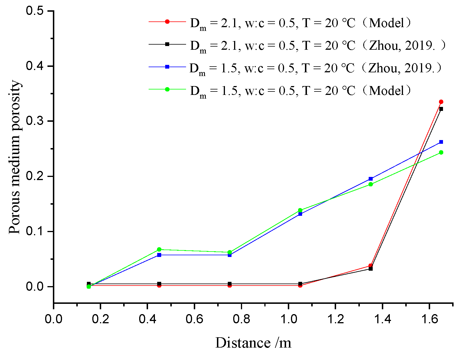
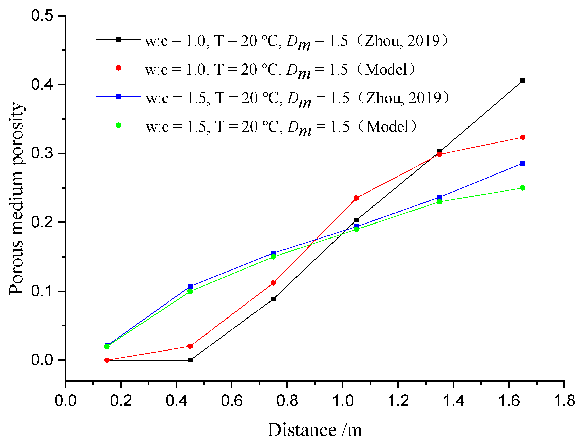
  • The percolation effect can lead to temporal and spatial variations in the injected medium’s porosity in the grouting process. The consistency between the predicted and measured results shows that the grouting diffusion law can be more accurately demonstrated by considering the real-time porosity variation.
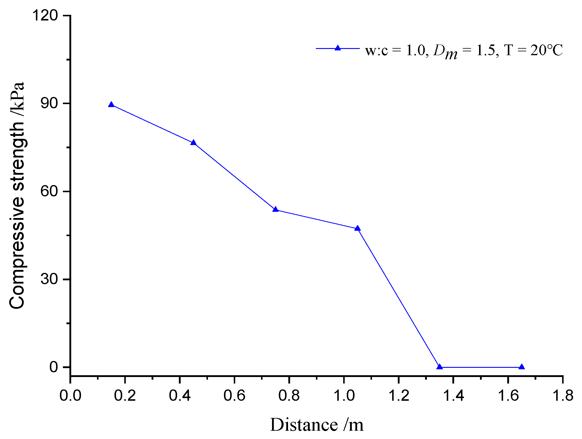
  • The change in the porosity of the injected medium affects the diffusion distance and repair effect of the cement slurry. The particles can be trapped in the grouting hole, resulting in a rapid decrease in the porosity of the media at the grouting hole. Therefore, it is difficult for the slurry to continue to diffuse, thus shortening the diffusion distance. Meanwhile, the decrease in porosity at the grouting hole will lead to the high compressive strength of the consolidated body. However, it also affects the remote repair effect of grouting, making it difficult to achieve the design’s mechanical properties.
  • The diffusion model is applied to the grouting parameter design of highway repair. It was found that the pavement bearing performance is greatly improved after grouting, indicating that it is reasonable to consider the change in porosity of the injected medium.

Author Contributions

Conceptualization, B.H. and X.C. (Xuemin Chen); methodology, Y.P.; software, C.W.; investigation, B.H.; resources, B.H.; writing—original draft preparation, C.W.; writing—review and editing, C.W. and X.C. (Xuanxuan Chu); supervision, M.S.; funding acquisition, M.S. All authors have read and agreed to the published version of the manuscript.

Funding

This research was funded by Key Laboratory for Detection and Maintenance Technology of Road and Bridge of Zhejiang Province, grant number 202102Z; Zhejiang Provincial Department of Transportation Science and Technology Planning project, grant numbers 2021013 and 2021012; and Zhejiang Academy of Transportation Sciences Research project, grant number ZK202201. The APC was funded by Mingsheng Shi.

Institutional Review Board Statement

Not applicable.

Informed Consent Statement

Not applicable.

Data Availability Statement

Data are available from the corresponding author.

Conflicts of Interest

The authors declare no conflict of interest.

References

  1. Luo, R.; Huang, T.; Zhang, D.; Lytton, R. Water vapor diffusion in asphalt mixtures under different relative humidity differentials. Constr. Build. Mater. 2017, 136, 126–138. [Google Scholar] [CrossRef]
  2. Pachideh, G.; Gholhaki, M.; Moshtagh, A. Experimental study on mechanical strength of porous concrete pavement containing pozzolans. Adv. Civ. Eng. Mater. 2020, 9, 38–52. [Google Scholar] [CrossRef]
  3. Ma, F.; Dong, W.; Fu, Z.; Wang, R.; Huang, Y.; Liu, J. Life cycle assessment of greenhouse gas emissions from asphalt pavement maintenance: A case study in China. J. Clean. Prod. 2021, 288, 125595. [Google Scholar] [CrossRef]
  4. Zhang, J.; Cai, J.; Pei, J.; Li, R.; Chen, X. Formulation and performance comparison of grouting materials for semi-flexible pavement. Constr. Build. Mater. 2016, 115, 582–592. [Google Scholar] [CrossRef]
  5. Guo, C.; Cui, C.; Wang, F. Case study on quick treatment of voids under airport pavement by polymer grouting. J. Mater. Civ. Eng. 2020, 32, 05020006. [Google Scholar] [CrossRef]
  6. Wang, C.; Diao, Y.; Guo, C.; Li, P.; Du, X.; Pan, Y. Two-stage column–hemispherical penetration diffusion model considering porosity tortuosity and time-dependent viscosity behavior. Acta Geotechnica 2022, 1–20. [Google Scholar] [CrossRef]
  7. Qin, L.; Guo, C.; Sun, W.; Chu, X.; Ji, T.; Guan, H. Identification of damage mechanisms of polymer-concrete in direct shearing tests by acoustic emission. Constr. Build. Mater. 2022, 351, 128813. [Google Scholar] [CrossRef]
  8. Qin, L.; Guo, C.; Sun, W.; Guan, H.; Yan, W.; Wang, F. Experimental investigation on the interfacial shear bond performance of non-water reacting polymer and concrete. Constr. Build. Mater. 2022, 331, 127351. [Google Scholar] [CrossRef]
  9. Zhang, L.; Wen, P.; Wang, C.; Di, S.; Yin, W. Advances in Non-excavation Grouting Reinforcement Materials in the Road Engineering. Mater. Rep. 2017, 31, 98–105. [Google Scholar]
  10. Ruan, W. Spreading model of grouting in rock mass fissures based on time-dependent behavior of viscosity of cement-based grouts. Chin. J. Rock Mech. Eng. 2005, 24, 2709–2714. [Google Scholar]
  11. Wang, H.; Wang, Q.; Min, F.; Chen, J. Research Progress of Grouting Sealing Materials. Mater. Rep. 2013, 27, 103–106. [Google Scholar]
  12. Pachideh, G.; Gholhaki, M. Effect of pozzolanic materials on mechanical properties and water absorption of autoclaved aerated concrete. J. Build. Eng. 2019, 26, 100856. [Google Scholar] [CrossRef]
  13. Seddighi, F.; Pachideh, G.; Salimbahrami, S.B. A study of mechanical and microstructures properties of autoclaved aerated concrete containing nano-graphene. J. Build. Eng. 2021, 43, 103106. [Google Scholar] [CrossRef]
  14. Anagnostopoulos, C.A. Effect of different superplasticisers on the physical and mechanical properties of cement grouts. Constr. Build. Mater. 2014, 50, 162–168. [Google Scholar] [CrossRef]
  15. Li, S.C.; Zheng, Z.; Liu, R.T.; Feng, X.; Sun, Z.Z.; Zhang, L.Z. Analysis of diffusion of grout in porous media considering infiltration effects. Chin. J. Rock Mech. Eng. 2015, 34, 2401–2409. [Google Scholar]
  16. Bennacer, L.; Ahfir, N.-D.; Bouanani, A.; Alem, A.; Wang, H. Suspended Particles Transport and Deposition in Saturated Granular Porous Medium: Particle Size Effects. Transp. Porous Media 2013, 100, 377–392. [Google Scholar] [CrossRef]
  17. Zhang, M.Q.; Zhang, W.; Sun, G. Evaluation technique of grouting effect and its application to engineering. Chin. J. Rock Mech. Eng. 2006, 25, 3909–3918. [Google Scholar]
  18. Wang, X. Research on Comprehensive Evaluation Technology of Grouting Effect in Underground Engineering. Bachelor’s Thesis, Beijing Municipal Engineering Research Institute, Beijing, China, 2009. [Google Scholar]
  19. Li, P.; Liu, J.; Shi, L.; Li, X.; Zhu, H.; Huang, D.; Kou, X. Two-phase analytical model of seepage during grout consolidation around shield tunnel considering the temporal variation in viscosity and the infiltration effect. Eur. J. Environ. Civ. Eng. 2020, 26, 4392–4415. [Google Scholar] [CrossRef]
  20. Yoon, J.; El Mohtar, C.S. A filtration model for evaluating maximum penetration distance of bentonite grout through granular soils. Comput. Geotech. 2015, 65, 291–301. [Google Scholar] [CrossRef]
  21. Axelsson, M.; Gustafson, G.; Fransson, Å. Stop mechanism for cementitious grouts at different water-to-cement ratios. Tunn. Undergr. Space Technol. 2009, 24, 390–397. [Google Scholar] [CrossRef]
  22. Zhou, Z.; Du, X.; Wang, S.; Zang, H. Analysis and engineering application investigation of multiple-hole grouting injections into porous media considering filtration effects. Constr. Build. Mater. 2018, 186, 871–883. [Google Scholar] [CrossRef]
  23. Ye, F.; Yang, T.; Mao, J.-H.; Qin, X.-Z.; Zhao, R.-L. Half-spherical surface diffusion model of shield tunnel back-fill grouting based on infiltration effect. Tunn. Undergr. Space Technol. 2019, 83, 274–281. [Google Scholar] [CrossRef]
  24. Ye, F.; Qin, N.; Han, X.; Liang, X.; Gao, X.; Ying, K. Displacement infiltration diffusion model of power-law grout as backfill grouting of a shield tunnel. Eur. J. Environ. Civ. Eng. 2022, 26, 1820–1833. [Google Scholar] [CrossRef]
  25. Du, X.; Liu, C.; Wang, C.; Fang, H.; Xue, B.; Gao, X.; Han, Y. Diffusion characteristics and reinforcement effect of cement slurry on porous medium under dynamic water condition considering infiltration. Tunn. Undergr. Space Technol. 2022, 130, 104766. [Google Scholar] [CrossRef]
  26. Zheng, Z.; Fan, F.; Pan, X.; Ma, C. Study on grouting penetration rule with filtration effect and grout–water interaction. Arab. J. Geosci. 2021, 14, 1830. [Google Scholar] [CrossRef]
  27. Mandelbrot, B. How long is the coast of Britain? Statistical self-similarity and fractional dimension. Science 1967, 156, 636–638. [Google Scholar] [CrossRef]
  28. Giudicianni, C.; Di Nardo, A.; Greco, R.; Scala, A. A community-structure-based method for estimating the fractal dimension, and its application to water networks for the assessment of vulnerability to disasters. Water Resour. Manag. 2021, 35, 1197–1210. [Google Scholar] [CrossRef]
  29. Hoxha, E.; Vidal, Y.; Pozo, F. Damage diagnosis for offshore wind turbine foundations based on the fractal dimension. Appl. Sci. 2020, 10, 6972. [Google Scholar] [CrossRef]
  30. Zhao, Z.; Ni, X.; Cao, Y.; Shi, Y. Application of fractal theory to predict the coal permeability of multi-scale pores and fractures. Energy Rep. 2021, 7, 10–18. [Google Scholar] [CrossRef]
  31. Deng, H.; Tian, G.; Yu, S.; Jiang, Z.; Zhong, Z.; Zhang, Y. Research on strength prediction model of sand-like material based on nuclear magnetic resonance and fractal theory. Appl. Sci. 2020, 10, 6601. [Google Scholar] [CrossRef]
  32. Niu, D.; Huang, D.; Zheng, H.; Su, L.; Fu, Q.; Luo, D. Experimental study on mechanical properties and fractal dimension of pore structure of basalt–polypropylene fiber-reinforced concrete. Appl. Sci. 2019, 9, 1602. [Google Scholar] [CrossRef]
  33. Wang, J.; Guo, Q.; Chen, W.; Liu, H. Study on Multi-Scale Coral Reef Pore Structure Identification and Characterization. Appl. Sci. 2022, 12, 5280. [Google Scholar] [CrossRef]
  34. Zhang, M.; Sun, H.; Song, C.; Li, Y.; Hou, M. Pores Evolution of Soft Clay under Loading/Unloading Process. Appl. Sci. 2020, 10, 8468. [Google Scholar] [CrossRef]
  35. Zhao, Y.; Wang, C.; Ning, L.; Zhao, H.; Bi, J. Pore and fracture development in coal under stress conditions based on nuclear magnetic resonance and fractal theory. Fuel 2022, 309, 122112. [Google Scholar] [CrossRef]
  36. Li, H. Quantitative prediction of complex tectonic fractures in the tight sandstone reservoirs: A fractal method. Arab. J. Geosci. 2021, 14, 1986. [Google Scholar] [CrossRef]
  37. Shi, W.; Wang, J.; Li, X.; Xu, Q.; Jiang, X. Multi-fractal characteristics of reconstructed landform and its relationship with soil erosion at a large opencast coal-mine in the loess area of China. Geomorphology 2021, 390, 107859. [Google Scholar] [CrossRef]
  38. Li, Y.; Wang, Z.; Pan, Z.; Niu, X.; Yu, Y.; Meng, S. Pore structure and its fractal dimensions of transitional shale: A cross-section from east margin of the Ordos Basin, China. Fuel 2019, 241, 417–431. [Google Scholar] [CrossRef]
  39. Wang, G.; Shen, J.; Liu, S.; Jiang, C.; Qin, X. Three-dimensional modeling and analysis of macro-pore structure of coal using combined X-ray CT imaging and fractal theory. Int. J. Rock Mech. Min. Sci. 2019, 123, 104082. [Google Scholar] [CrossRef]
  40. Nayak, S.R.; Mishra, J.; Palai, G. Analysing roughness of surface through fractal dimension: A review. Image Vis. Comput. 2019, 89, 21–34. [Google Scholar] [CrossRef]
  41. Ni, G.; Li, S.; Rahman, S.; Xun, M.; Wang, H.; Xu, Y.; Xie, H. Effect of nitric acid on the pore structure and fractal characteristics of coal based on the low-temperature nitrogen adsorption method. Powder Technol. 2020, 367, 506–516. [Google Scholar] [CrossRef]
  42. Guo, R.; Xie, Q.; Qu, X.; Chu, M.; Li, S.; Ma, D.; Ma, X. Fractal characteristics of pore-throat structure and permeability estimation of tight sandstone reservoirs: A case study of Chang 7 of the Upper Triassic Yanchang Formation in Longdong area, Ordos Basin, China. J. Pet. Sci. Eng. 2020, 184, 106555. [Google Scholar] [CrossRef]
  43. Miao, T.; Yu, B.; Duan, Y.; Fang, Q. A fractal model for spherical seepage in porous media. Int. Commun. Heat Mass Transf. 2014, 8, 71–78. [Google Scholar] [CrossRef]
  44. Yu, B.; Cheng, P. A fractal permeability model for bi-dispersed porous media. Int. J. Heat Mass Transf. 2002, 45, 2983–2993. [Google Scholar] [CrossRef]
  45. Zhou, Z.; Cai, X.; Du, X.; Wang, S.; Ma, D.; Zang, H. Strength and filtration stability of cement grouts in porous media. Tunn. Under-Ground Space Technol. 2019, 89, 1–9. [Google Scholar] [CrossRef]
  46. Bohloli, B.; Morgan, E.K.; Grøv, E.; Skjølsvold, O.; Hognestad, H.O. Strength and filtration stability of cement grouts at room and true tunneling temperatures. Tunn. Undergr. Space Technol. 2018, 71, 193–200. [Google Scholar] [CrossRef]
  47. Wang, C.; Guo, C.; Du, X.; Shi, M.; Liu, Q.; Xia, Y. Reinforcement of silty soil with permeable polyurethane by penetration injection. Constr. Build. Mater. 2021, 310, 124829. [Google Scholar] [CrossRef]
  48. Herzig, J.P.; Leclerc, D.M.; Le Goff, P. Flow of Suspensions through Porous Media—Application to Deep Filtration. Ind. Eng. Chem. 1970, 62, 8–35. [Google Scholar] [CrossRef]
  49. Kim, J.-S.; Lee, I.-M.; Jang, J.-H.; Choi, H. Groutability of cement-based grout with consideration of viscosity and filtration phenomenon. Int. J. Numer. Anal. Methods Geomech. 2009, 33, 1771–1797. [Google Scholar] [CrossRef]
  50. Gao, Z.; Wen, P.; Wang, C.; Shu, C.; Wang, X. Grouting seepage mechanism and reinforcement effect of alkali-activated materials in road base. Arab. J. Geosci. 2021, 14, 1319. [Google Scholar] [CrossRef]
Figure 1. Variation in porosity of porous media with distance for each test point in different mass fractal dimensions in experiments and models.
Applsci 13 01919 g001
Figure 2. The variation law of porosity of pore media with distance at each test point with different water–cement ratios in the test and model.
Applsci 13 01919 g002
Figure 3. Variation pattern of uniaxial compressive strength versus distance for each test point (the water–cement ratio is 1.0; the fractal dimension of pores is 1.5; temperature is 20 °C).
Applsci 13 01919 g003
Figure 4. Variation pattern of microstructure versus distance for each test point. (a) 0.15 m; (b) 0.45 m; (c) 0.75 m; (d) 1.05 m.
Applsci 13 01919 g004
Figure 5. Micromorphology after binarization treatment. (a) 0.15 m; (b) 0.45 m; (c) 0.75 m; (d) 1.05 m.
Applsci 13 01919 g005
Figure 6. Proportion of pores and cracks in SEM morphology.
Applsci 13 01919 g006
Figure 7. Cracked state of the pavement.
Applsci 13 01919 g007
Figure 8. Schematic diagram of grouting design.
Applsci 13 01919 g008
Figure 9. Drilling process.
Applsci 13 01919 g009
Figure 10. Cement grouting process.
Applsci 13 01919 g010
Figure 11. Deflection changes before and after grouting.
Applsci 13 01919 g011
Table 1. Selection of model parameters.
ParametersWater–Cement Ratio of Cement Slurry (w:c)Fractal Dimensions of the Pore/DmOther Parameters
Value1.01.5T = 20 °C
1.52.1
Disclaimer/Publisher’s Note: The statements, opinions and data contained in all publications are solely those of the individual author(s) and contributor(s) and not of MDPI and/or the editor(s). MDPI and/or the editor(s) disclaim responsibility for any injury to people or property resulting from any ideas, methods, instructions or products referred to in the content.

