Abstract
As one of the key techniques used in the perception layer of the Industrial Internet of Things (IIoT), radio frequency identification (RFID) has been widely applied for object tracing, smart warehouse management, product line monitoring, etc. In most applications, conveyor belts are prevalently implemented to accelerate the sorting efficiency for goods management. However, in such a system, tags quickly go through the reader’s reading range resulting in constant changing of the tag set and limited participating time of moving tags. As a result, it poses more challenges to the tag identification problem in mobile systems than in traditional static applications. In this work, a novel admission-control-based dynamic query tree (ACDQT) protocol is proposed for fast-moving tag identification. In ACDQT, two main strategies are developed, i.e., multi-round admission control (MRAC) and dynamic query tree recognition (DQTR). In MRAC, the reading process of multiple rounds is analyzed, and the number of admitted tags in each round is optimized. Thus, the tag lost ratio is guaranteed, and the identification process can be effectively accelerated. In DQTR, colliding tags are grouped into multiple subsets with the help of consecutive colliding bits in tag responses. By constructing a dynamic query tree, the number of collision slots is greatly reduced, and the identification efficiency in a single round is improved significantly. With MRAC and DQTR, ACDQT can support higher tag flow rate in mobile systems than existing works. Both theoretical analyses and simulation results are presented to demonstrate the effectiveness of ACDQT.
1. Introduction
Industry 4.0, which is triggered by the Industrial Internet of Things (IIoT) , has become the current trend of automation and data exchange in manufacturing technologies [1]. Thanks to the automatic identification techniques, such as radio frequency identification (RFID) and wireless sensors, used in the perception layer of the IIoT [2], the efficiency of modern manufacturing is greatly improved. As a non-contact identification technology, RFID has been widely used in various applications, such as object tracking, smart warehouse management, product line monitoring, etc. A typical RFID system usually consists of readers, tags and a back-end server. Each tag is identified by a unique identifier and sends data information by backscattering the reader’s signal. The back-end server is used to store tag information for further processing and analyses.
In RFID systems, the reader usually needs to recognize a large number of unknown tags within its reading range. When multiple tags reply simultaneously, a collision occurs where the reader cannot successfully decode the received message [3]. Unknown tag identification has always been one of the most critical techniques to enable object tracing and goods management in RFID systems. In recent research, lots of RFID tag identification protocols have been proposed. Among them, tree-based ones that make use of bit tracking technology [4,5] exhibit better performance, e.g., higher system efficiency and shorter identification delay. In such protocols, the reader usually divides colliding tags into multiple subsets with tree splitting. Thanks to the position information of colliding bits in the received message, the splitting process is more efficient. The most representative tree-based protocols are collision tree (CT) [4], collision window tree (CwT) [5] and M-ary collision tree (MCT) [6]. These algorithms use one or more colliding bits to split colliding tags into multiple subsets to accelerate the identification process. Recently, Su et al. proposed some tree-based algorithms, e.g, the dual prefix probing (DPPS) [7] and group-based tree splitting (GBSA) [8] to quickly identify tags. However, existing works make little use of the collision information. There is still room for improvement in bit-tracking-based tree splitting algorithms. Moreover, these works only consider the identification efficiency of a single reading round in static environments. The impact of tag mobility on the identification process lacks intensive study.
In most applications, conveyor belts are widely used to accelerate the sorting efficiency for goods management [9,10,11]. For example, more and more airports have used RFID technology to place luggage on conveyor belts for fast identification, and other applications have also identified tagged goods on conveyor belts, such as the traditional retail giant Walmart [9]. In such systems, one or more RFID readers are mounted above or beside the conveyor belt in some fixed positions. Objects attached with RFID tags move with the conveyor belt. Readers are responsible for collecting the ID information of all passing tags. Usually, tags’ IDs are unknown, and all tags send messages to the reader only when they receive the reader’s query request. Without any prior information, the reader cannot aim at any specific tag in its query request. One common strategy is carrying a query prefix in the reader’s query request. If a tag matches with the received prefix, it replies to the reader. When more than one tag replies simultaneously, a collision occurs which increases the identification delay.
The identification task is more challenging in mobile systems where tags quickly go through the reader’s reading range. Tags have a very limited time to participate in the identification process. Therefore, a tag may be unrecognized after it moves out of the reader’s reading range, i.e., becomes a lost tag [12]. With higher moving speed, the tag lost probability is larger. In the literature, some works try to reduce the tag lost ratio in mobile systems with either mathematic modeling or group scheduling strategies. For example, Aloson et al. analyzed the tag lost ratio with a Markov chain model [12]. Gotfryd et al modeled a dynamic RFID system for an optimal configuration [13]. In [14,15], some two-phase identification protocols are proposed. However, the tag lost ratio of existing works is large, especially when the tag’s moving speed increases.
In this work, we improve the identification efficiency of mobile RFID systems in two aspects, i.e., controlling the participating tags and accelerating the recognition process in each reading round. In general, we propose a novel admission-control-based dynamic query tree (ACDQT) protocol for mobile RFID tag identification. The main contributions are as follows,
- The identification process in mobile systems is analyzed, and a new multi-round admission control (MRAC) algorithm is developed to optimize the number of tags admitted in each reading round. With MRAC, the tag lost ratio is guaranteed, and the identification efficiency in each round is effectively improved;
- A dynamic query tree recognition (DQTR) algorithm is proposed to reduce the identification delay in each reading round. With DQTR, colliding tags are divided into more subsets based on the number of consecutive colliding bits; thus, the tag recognition efficiency is improved;
- Theoretic analysis is conducted to analyze the performance of DQTR in a single reading round. Moreover, numerous simulation results are presented to demonstrate the effectiveness of the proposed algorithm. Compared with existing benchmark works, the proposed ACDQT is proven to support higher tag flow rate with a lower tag lost ratio.
The remainder of this work is organized as follows: Section 2 introduces some representative tag identification protocols in both static and mobile systems. In Section 3, a fast-moving RFID tag identification system model is exhibited, and the frame structure and commands are described. Next, in Section 4, the proposed ACDQT protocol including the admission control and recognition strategies is described in detail. Then, theoretical analysis is conducted to obtain the identification delay of a single reading round in Section 5. The simulation results are illustrated in Section 6. Finally, Section 7 gives some conclusion remarks.
2. Related Works
In this section, we review some representative tag identification protocols for both static and mobile RFID systems.
In static systems, the tag set is assumed unchanged during the identification process. In such systems, the key problem is to reduce tag collisions, especially when the number of tags is large. In general, tag identification protocols mainly consist of two categories, i.e., the aloha-based, and the tree-based ones. In the first category, the reader identifies tags with a frame-slotted manner, and a tag replies to the reader with a randomly selected slot in each frame. However, using a random response manner, aloha-based protocols are of low efficiency. To improve the performance, some tag number estimation and frame adjustment strategies are proposed based on the statistical information of tag responses. For example, the Q-algorithm dynamically adjusts frame length with the feedback of slot status [16]. The maximum likelihood estimation algorithm estimates the number of tags with the Bayes method to optimize frame length settings in a dynamic frame-slotted aloha protocol [17]. In the second category, the reader identifies tags with a tree splitting method by grouping colliding tags into smaller subsets, such as query tree (QT) [18], binary tree splitting (BTS) [19], collision tree (CT) [4], etc. The identification process of these protocols follows a tree splitting structure in which each non-leaf vertex in the tree corresponds to a collision slot, and each leaf vertex refers to a successful or idle slot.
With a bit tracking technique, identification efficiency of tree-based protocols is efficiently improved. In the collision tree (CT) protocol [4], the reader splits colliding tags into two subsets based on the position of the first colliding bit without generating any idle slots. However, the splitting process is slow, and many collision slots are generated. Next, Landaluce et al. proposed a collision window tree (CwT) protocol [5] that uses a heuristic bit window strategy in the collision tree splitting process in order to reduce identification time and tags’ communication overhead. In CwT, the number of total slots are increased, and the reader has to transmit more query messages to identify all tags. To further reduce collision slots, Su et al. proposed a dual prefix probing (DPPS) protocol [7] that makes use of the first two consecutive colliding bits to split colliding tags into more subsets. In [6], Zhang et al. proposed an M-ary collision tree (MCT) protocol to further accelerate the splitting process by making use of more colliding bits information. Recently, Su et al. also proposed a modified dual prefixes matching (MDPM) algorithm [20] that makes a bit query strategy in the M-ary query tree. Liu et al. designed a multi-bit identification collision tree (MICT) algorithm [21] and Hailemariam et al. developed a knowledge-based query tree algorithm [22]. However, these works only consider a static situation. In mobile systems, the tag set changes dynamically and tag participating time is very limited. These works cannot effectively identify tags in such situations.
In mobile situations, when the reader begins a new reading round, tags that have been recognized in preceding rounds may still be in the reader’s reading range which results in duplicate recognition. Meanwhile, some newly arrived tags may join the identification process which further aggravates the tag collision situation. How to effectively control participating tags and quickly identify moving tags is very challenging. In the past decade, some works considered the moving tag identification problem. In [23], Saranga et al. first proposed an aloha-based framework for both static and mobile environments. Next, Alonso et al. analyzed the tag lost ratio in dynamic RFID systems and gave optimal configurations of frame-slotted aloha algorithms [24,25,26]. Later on, Kang et al. developed a reliable splitting strategy in an aloha algorithm to accelerate the identification process of moving tags [27]. Gotfryd also modeled the dynamic RFID system in [13]. However, these works only consider a basic aloha-based algorithm in which the identification efficiency is low. In [28], Zhu et al. developed a schedule-based RFID anti-collision protocol to maximize tag moving speed. They considered the identification deadlines of moving tags and scheduled an optimal number of tags to compete for the channel accordingly. With a schedule strategy, the identification efficiency is greatly improved.
In recent research, some new strategies have been developed for mobile RFID systems. In [14], Liu et al. proposed a blocking collision tracking tree algorithm to divide the identification process into two phases, one for staying tags and one for arriving tags. Making use of bit tracking to split tags into appropriate subsets, the identification efficiency is increased. In [6], Zhang et al. further improved the tag identification efficiency with a bit tracking technique. They developed an efficient bit-detecting (EBD) algorithm to quickly recognize unknown tags in each reading round. Thus, the proposed algorithm can support a much higher tag flow rate in mobile systems. Later on, Jia proposed a dynamic collision tree protocol to deal with arriving tags [29]. Yu et al. developed a dynamic tag population estimation algorithm with a Kalman filter [30]. In [31], Liu et al. designed a rate-adaptive algorithm to revisit the reading rate with mobility. Chen et al. also proposed a collision avoidance algorithm for mobile RFID devices [32]. However, the control strategies and reading methods of these works need further improvement to support higher tag moving speeds. To sum up, Table 1 compares different RFID tag identification protocols in static and moving situations.

Table 1.
Comparison of different RFID tag identification protocols in static and moving situations.
3. System Model
In this work, we consider the widely used conveyor belt applications and present a fast-moving RFID tag identification system model in this section. Then, the frame structure and some commands used in the tag identification process are described.
3.1. A Fast Moving RFID Tag Identification System
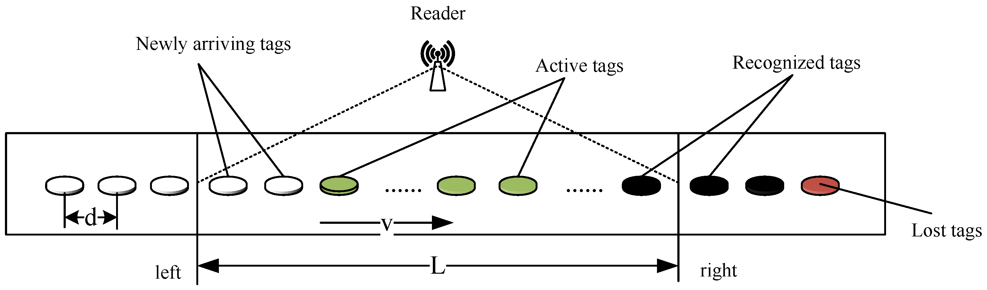
Among massive RFID applications, conveyor belt systems with RFID readers and tags are popular in various industries. In these applications, objects with RFID tags attached are placed on a conveyor belt. One or more RFID readers are usually mounted in a fixed position above (or beside) the conveyor belt. As the conveyor belt quickly moves, tags continuously move into and out of the reader’s reading range. As is demonstrated in Figure 1, a general conveyor belt system is considered. Assume that each object has one tag attached that has a 96-bit unique identifier. The objects are denoted by their attached tags hereafter. In the model, tags are placed on the conveyor belt in series, and the distance between two adjacent tags is d m. The moving speed of the conveyor belt is v m/s. For simplicity, a single reader that is mounted above the conveyor belt is considered, and its coverage range is L m.
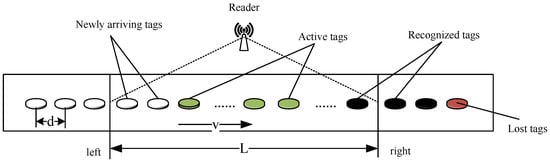
Figure 1.
Conveyor-belt-oriented fast-moving RFID system model.
Tags first enter from the left side of the reader’s reading range, then pass through a limited signal area and finally leave from the right side of the reading range. Affected by the moving speed and limited reading range, there may be situations where some tags pass through the reader’s coverage area without been recognized. We define this type of tags as lost tags, and the tag lost ratio is defined as the ratio of the number of tags passing through the reader’s coverage area without being identified to the total number of tags passing through the reader’s reading range within a certain time. The identification efficiency is defined as the average number of tags successfully identified per second. The goal of this work is to increase tag identification efficiency while minimizing the tag lost ratio in fast-moving RFID systems.
Compared with traditional static RFID systems, tag identification in mobile RFID systems is more challenging. The main reasons are twofold, as in the following.
- Limited participating time: RFID tags stay in the reader’s reading range for a limited time, especially in high mobility situations. They enter from the left side of the reading range and leave from the right side. Tags will receive commands sent by the reader only when they are within the reader’s reading range. With collision signals, the probability that a tag’s response signal can be successfully recognized by the reader is low. For traditional static RFID systems, tags are always within the coverage range of the reader and can repeatedly contend to send response signals until being recognized since there is no participating time limitation.
- Random access manner: In each reading round, tags with various positions in the reading range will not have different priorities to access the channel. All tags within the reading range have the same chance, i.e., the same identification possibility. This random access property will lead the reader to identify newly arrived tags and earlier entered ones within the range in the same reading round. Thus, tags entering at the early stage may not be identified after they leave the reading range, which will aggravate the tag lost situation.
To facilitate the identification process, tags are limited to being recognized at most one time. When a tag is recognized by the reader, it will keep silent and not participate in subsequent identification processes until it leaves the reading range. Thus, the recognized tags will not affect the identification process of other participating tags.
3.2. Transmission Model
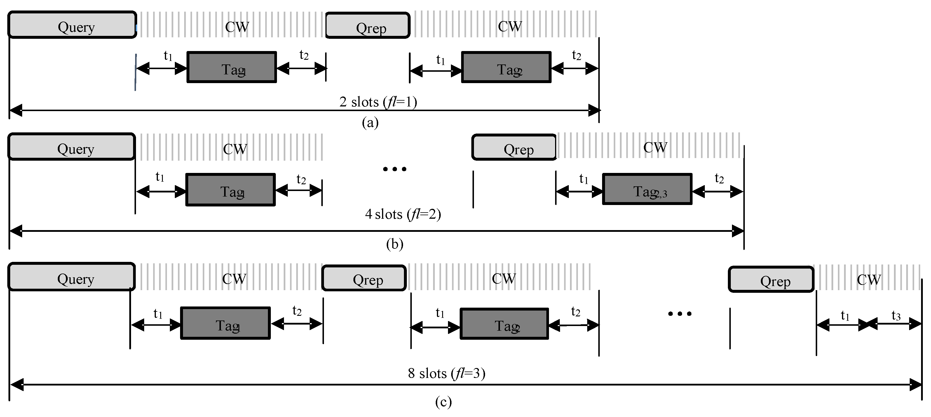
In this work, we use a frame-slotted model similar to the de facto standard EPC Global C1G2 [16]. In the model, time is divided into multiple frames, and each frame consists of several synchronized slots. The interaction between the reader and tags in each frame is shown in Figure 2, where three types of frames are illustrated, i.e., frames with two, four and eight slots. Here, the number of time slots in a frame is determined by the frame length parameter contained in the command.
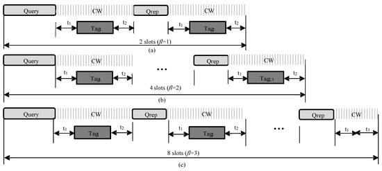
Figure 2.
Frame slot structure: (a) when , the frame consists of two slots; (b) when , the frame consists of four slots; (c) when , the frame consists of eight slots.
As shown in Figure 2, each frame begins with the reader’s command and is followed with k consecutive slots, and each slot starts with the short command except for the first slot of a frame. This is because the first slot starts automatically right after the command. Each slot has three states, i.e., collision, idle and successful. A collision slot means that two or more tags reply simultaneously in the same slot. In such slots, the reader cannot effectively decode the received signal. In a successful slot, there is only one tag response so that the reader can successfully recognize this tag. Note that we do not consider capture effect as most works in the literature [3,4,5,6,7] since it has a similar effect on comparable protocols. Finally, an idle slot means that there is no tag response. In each frame, it takes the reader and time to transmit and commands, respectively. The time for tag response message transmission is . According to [16], is the time taken from the reader transmission to the tag response, is the interrogator response time required if a tag is demodulating the interrogator signal, and is the time a reader waits after if there is no tag response.
Moreover, the structures of commands and tag response messages are given in Table 2. The command consists of five components, i.e., head information, length of matching prefix , matching prefix , number of consecutive colliding bits and CRC-16. The head segment contains the command, address, mask and other information as defined in [16]. The and inform tags with the common prefix of the attending tags and the number of slots in the current frame, respectively; informs tags with the length of , which guarantees that tags can correctly obtain in the command. only contains command information. In the tag response, a 9-bit preamble accompanied by the remaining tag ID is transmitted. Note that we do not use CRC in the tag’s response message because the Manchester coding used in tag-to-reader message transmission has the ability to check errors in a bit-wise manner.
Table 2.
Command and data frame structure.
4. Admission-Control-Based Dynamic Query Tree Protocol for Fast Moving Tag Identification
In this section, a novel admission-control-based dynamic query tree (ACDQT) protocol is developed to effectively identify fast-moving tags while maintain a minimum tag lost ratio. In conveyor belt systems, the tag set constantly changes during the identification process. For easy implementation, the reader divides the identification process into multiple reading rounds. In each round, there may be three types of tags in the reader’s coverage area, that is, deactivated tags that were recognized in preceding rounds, active tags that are participating in the recognition of the current round and newly arrived tags that are not participating in the recognition of this round as illustrated in Figure 1.
The main idea of ACDQT is to restrict the number of participating tags with admission control and recognize them with a high-efficiency dynamic query tree protocol in each reading round. In general, the reader first performs three rounds to estimate the tag flow rate. Next, it controls the number of admitted tags based on the estimation and system requirement. Each subsequent round only needs to control a similar number of incoming tags to ensure that the entire system meets the minimum tag lost ratio requirement. When there are enough tags entering the reader’s reading range, a new round begins. In each round, a dynamic query tree protocol is designed to quickly identify tags. When collision occurs, the reader first checks the position of the first colliding bit k and the number of consecutive colliding bits after that position. Then, it divides these tags into smaller groups according to the number of consecutive collision bits. Compared with existing bit tracking protocols, the number of subsets of ACDQT is more flexible and appropriate. Thus, the proposed protocol can significantly reduce the number of collision slots and speed up the identification process. Before describing the proposed ACDQT protocol, Table 3 defines some symbols, functions and commands used in the paper.
Table 3.
Symbol definitions.
4.1. Multi-Round Admission Control Algorithm
In conveyor belt systems, tags continuously move through the reader’s reading range. The participating time of a tag greatly affects the identification efficiency. In traditional methods, a newly arriving tag directly joins the current round or waits to participate in the subsequent round. If tag flow rate and identification efficiency differ widely, the identification process will be inefficient with much idle time or collisions. In this work, a multi-round admission control (MRAC) algorithm is proposed to improve the identification efficiency.
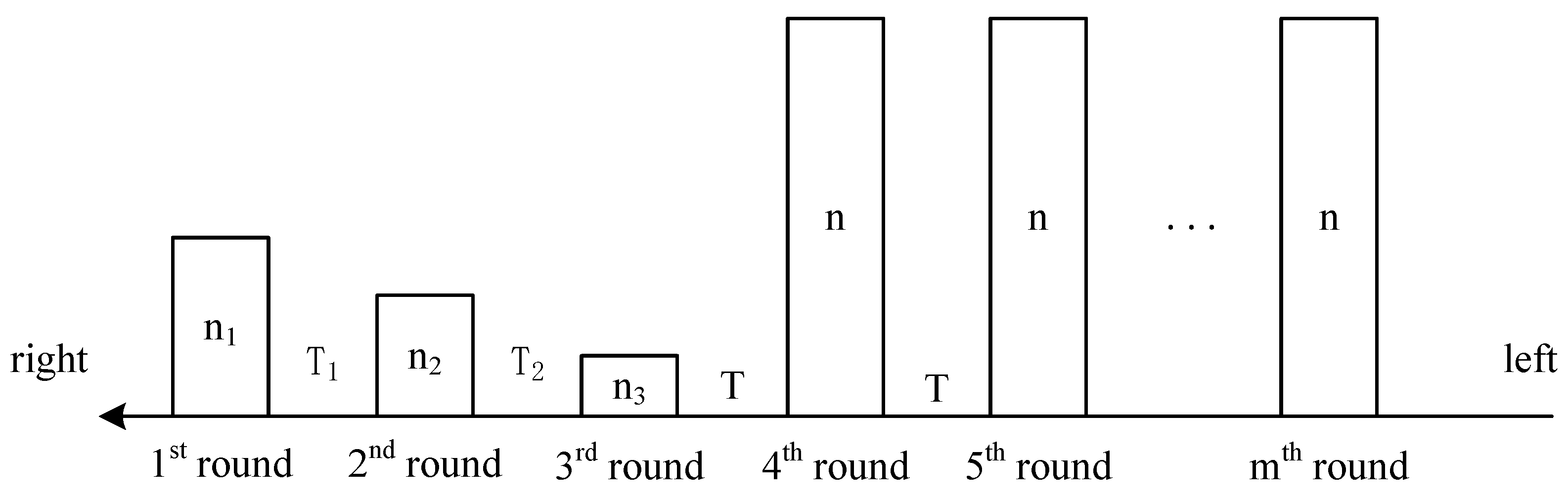
The identification process of MRAC is abstracted in Figure 3, where n is the number of tags participating in each round, and T is the time interval of two consecutive rounds. At the beginning, there is no tag in the reading range. With the conveyor belt moving for s, there are tags arrived, and the reader starts the first round immediately. Suppose after s, the reader recognized all tags and starts the second round. During this time, the number of newly arrived tags is . Similarly, if the second round takes s, the number of newly arrived tags in this round is , and the recognition time in round 3 is . Suppose the conveyor belt keeps moving at a constant speed, the tag flow rate is obtained by

Figure 3.
Multi-round tag recognition for conveyor belt systems.
The average time needed to identify one tag in the first three rounds is
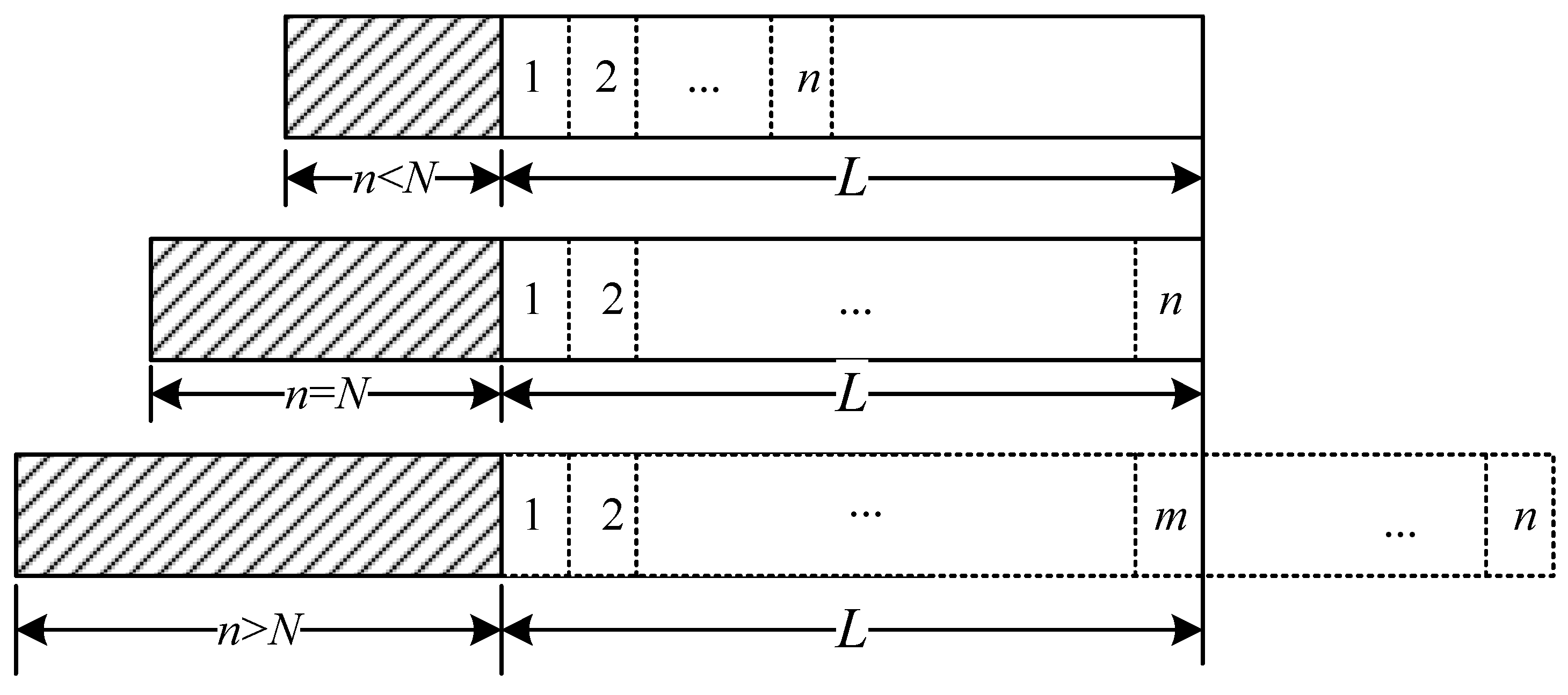
With the estimation results and system requirement, the number of tags admitted to participate in the subsequent round can be calculated. In what follows, we analyze the influence of participating tag number n on the tag lost ratio in one round. As given in Figure 4, the identification process in a single round is considered in three cases, i.e., , and , where N is the maximum number of tags that the reader can recognize in a normal situation. In Figure 4, the shadowed rectangles give the number of participating tags, the white rectangles represent the number of slots used to identify tags, and L is the reader’s coverage range.
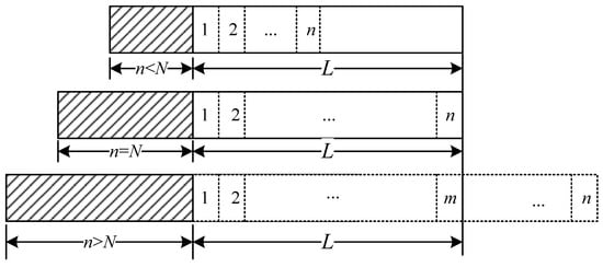
Figure 4.
Recognition process in a single round.
When , the reader can recognize all participating tags before they move out of its reading range. There is some time left before the reader starts the next round. Thus, the system does not reach its optimal situation. When , the reader completely recognizes all participating tags and makes full use of time in such a reading round. There is no slot waste, and the tag lost ratio . However, when , the time needed to recognize all n tags is greater than the maximum staying time of these tags. Therefore, some of them may become lost. To balance the tag lost ratio and identification efficiency, the number of admitted tags in each round is critical.
When , the number of tags that can be successfully recognized by the reader is m, . Since more tags will worsen the collision situation, the actual number of recognized tags is smaller than the maximum value that a reader can recognize in a normal situation. In different positions of the reading range, the tag lost possibility varies. The first entering tag in a reading round will move for distance to leave the reading range. During this time, the average number of tags that can be identified by the reader is given by
Since all tags will move into this position and experience a similar identification process, for a tag in the first position, its lost probability is given by
Therefore, the average number of lost tags in the first position is . Similarly, in the ith position of the tag line, the tag will move for distance to leave the reading range. Then, the average number of tags identified during this time is
Then, when a tag is in the ith position, the probability of being unrecognized after it moves out of the reader’s reading range is given by
Note that is the number of lost tags prior to the ith position. The number of tags that will participate in the identification process of the ith position can be calculated by . The average number of lost tags in the ith position is . Then, the tag lost ratio is
Substituting (5) and (6) into (7), the tag lost ratio of a single reading round is obtained. By solving (7), the number of tags participating in each round is determined to meet the system requirement on the tag lost ratio. With MRAC, the reader waits for a short time to allow enough tags to enter the reading range and starts the identification process in each subsequent round.
4.2. Dynamic Query Tree Recognition Algorithm
In this section, we propose a dynamic query tree recognition (DQTR) algorithm to effectively identify tags in each round. DQTR follows the query tree recognition process with multiple branches. In general, the reader divides tags in each colliding slot with the help of consecutive colliding bits in the tags’ responses. When the reader detects a collision, it first checks the position of the first colliding bit p and the number of consecutive collision bits k after this position. Then, it divides colliding tags into subsets to accelerate the identification process. Compared with existing bit tracking protocols, DQTR solves colliding tags with a more flexible and appropriate manner which significantly reduces time costs. The detailed algorithm is given as follows.
At the beginning of a reading round, the reader initializes queue . Then, it obtains and broadcasts to start the first frame. Note that is to obtain the first item and delete it from queue Q.
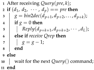
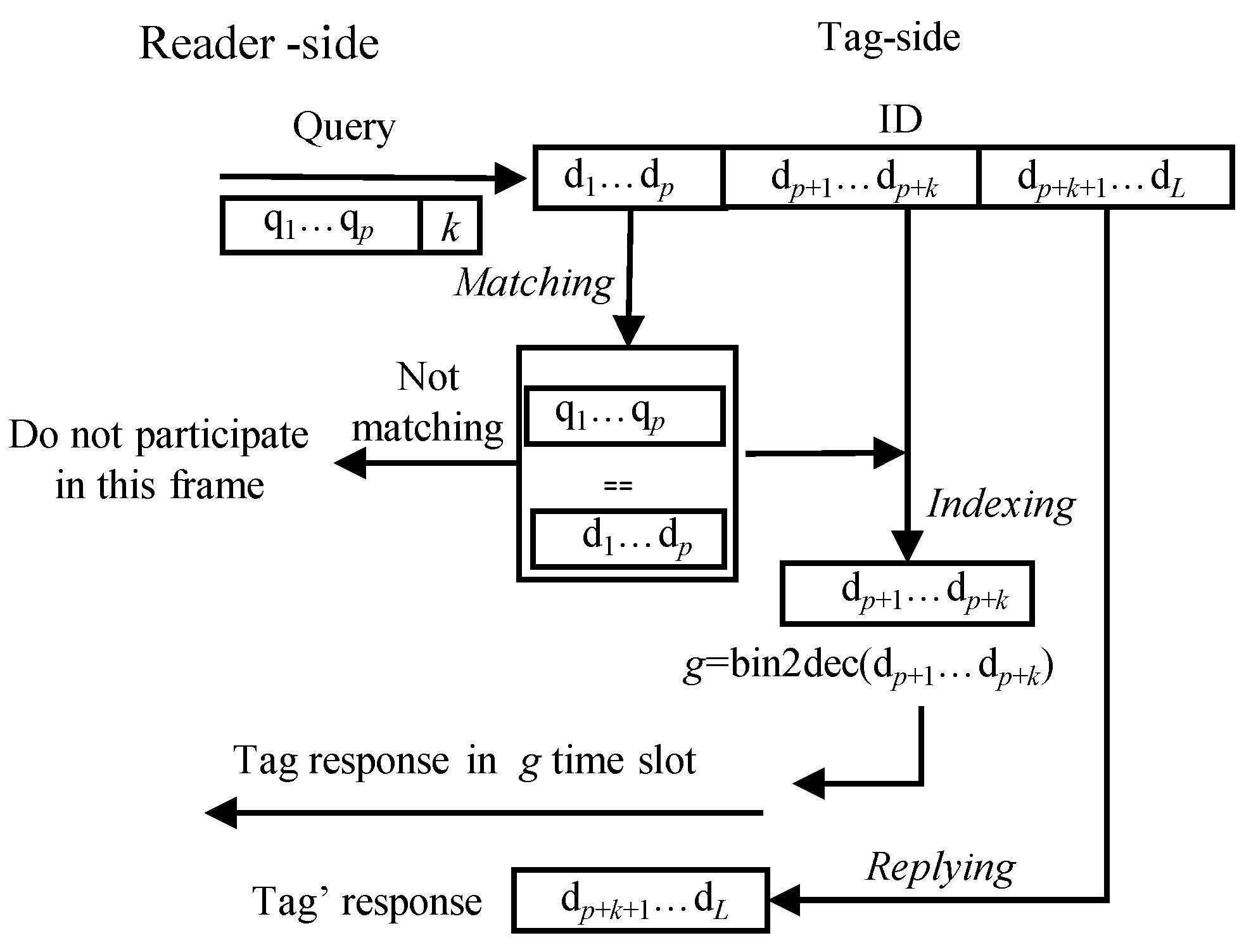
On receiving the reader’s command, tags execute matching, indexing and replying operations in sequence as shown in Figure 5.

Figure 5.
Tag’s operation after receiving the reader’s Query command.
- Matching: A tag first compares its ID with the matching prefix . If it matches, the tag transits to the transmission state and will participate in the current frame. Otherwise, it waits for the next command.
- Indexing: If a tag is in the transmission state, it checks the slot index from to bits in its ID and converts into a decimal number g, i.e.,
- Replying: If , the tag replies its remaining ID, i.e., (, ,…, ), to the reader. Otherwise, it waits for the reader’s command, and reduces g byone after receiving this command until zero.
After receiving tags’ responses in each slot, the reader determines the state of the current slot and identifies tags. In summary, there are four types of slots to appear.
- Singleton slot: If there is only one tag reply, the received message can be successfully decoded. Then, the reader identifies the tag and recovers its ID withwhere ‖ is the concatenating operation.
- Two readable slot: There are replies from two tags in the slot, and the received message contains only one colliding bit. Since the tag’s ID is unique, the reader can recognize the two tags in one slot. For example, the message received by the reader is , where is the colliding bit. The two tag IDs to be identified are
- Idle slot: If the reader receives no message at the slot, it is an idle slot.
- Collision slot: When more than two tags reply simultaneously in the slot, a collision slot occurs since the reader cannot recover any ID information. In this slot, the reader checks the position of the first colliding bit and the number of consecutive colliding bits after this position. Next, it obtains the parameters for subsequent frames. For example, if the decoded message is “1xx01”, the frame parameters are obtained by calculatingThen, the reader pushes (, ) to Q.
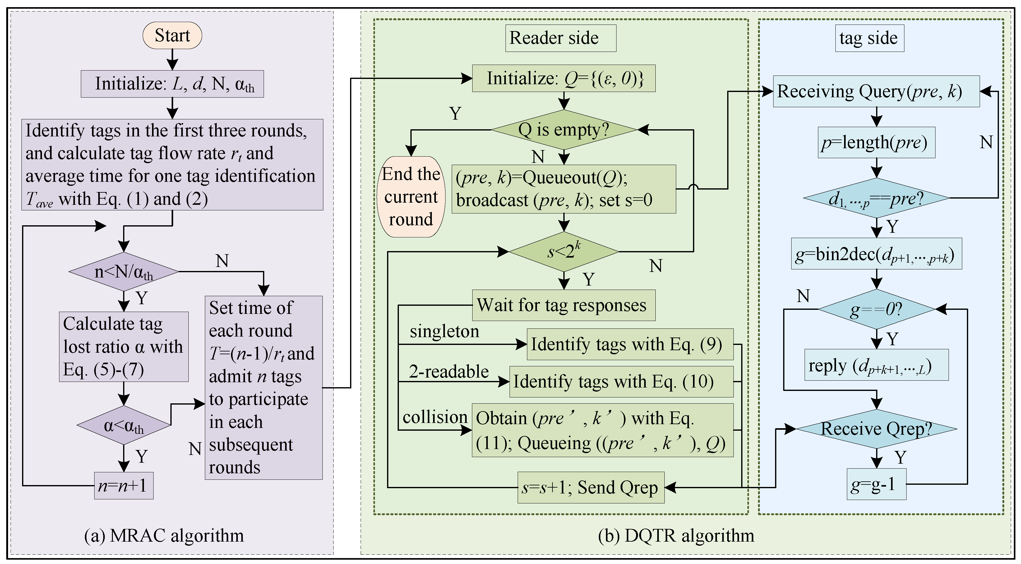
After executing all slots in the current frame, the reader checks whether Q is empty. If Q is empty, it terminates the identification of this round since all the tags are identified. Otherwise, it obtains frame parameters by and sends command to start the next frame. More specifically, Algorithms 1 and 2 give the pseudo-codes of the reader’s and tags’ operations in DQTR, respectively. The whole identification process of ACDQT is also given in Figure 6.
| Algorithm 1: Reader’s Operations |
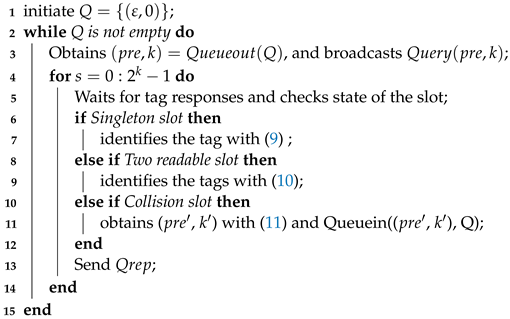 |

Figure 6.
Flowchart of the proposed ACDQT algorithm: (a) the admission control phase with MRAC; (b) the identification phase in each round with DQTR.
| Algorithm 2: Tags’ Operations |
 |
An Example
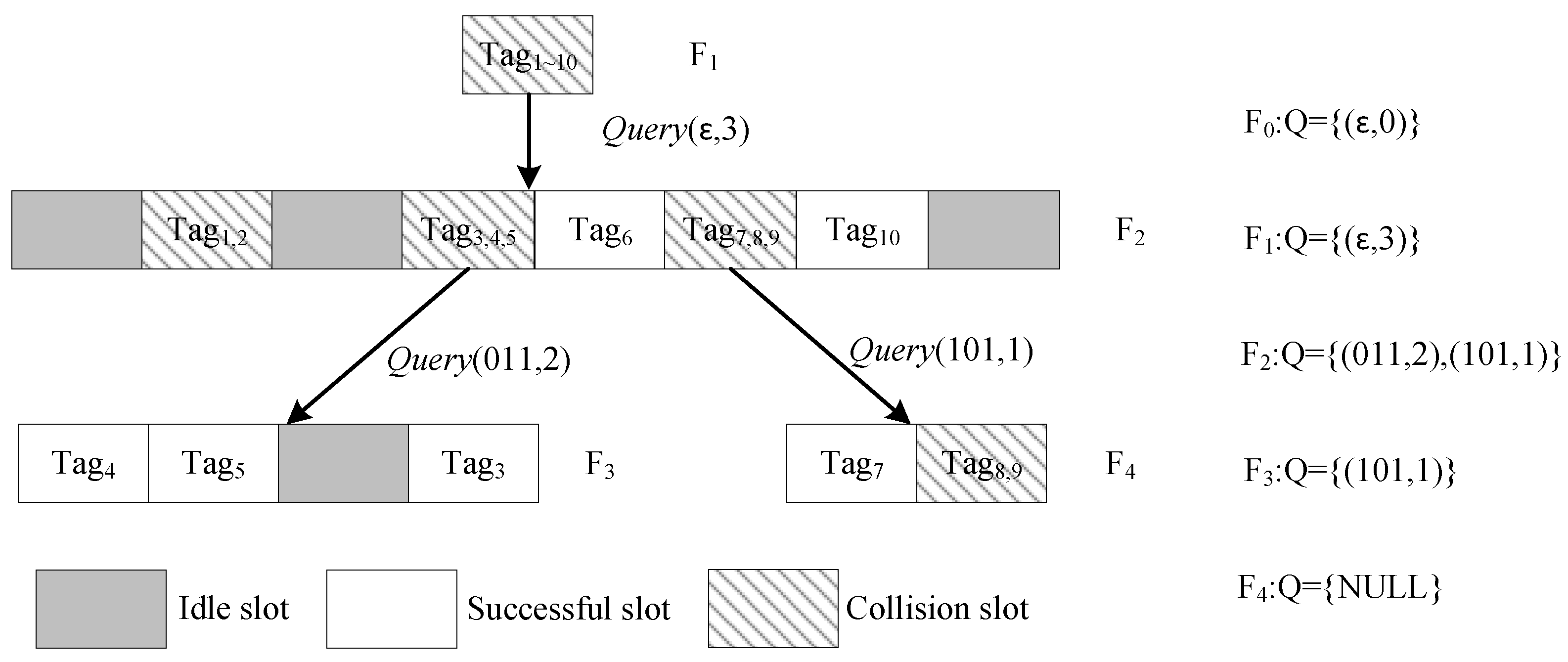
To clearly show the DQTR algorithm, Figure 7 illustrates an example of the identification process for 10 tags, and the tag IDs are given in Table 4. In Figure 7, refers to the ith frame, and the queue Q of each frame is also given in the right side.
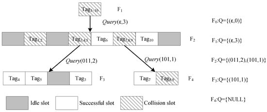
Figure 7.
Example of DQTR recognition process.
Table 4.
Tags’ ID information.
At the beginning, the reader initializes queue . In the first frame , it obtains parameters from Q and broadcasts . Note that the initial frame consists of only one collision slot, since all tags will match with prefix . After receiving tags’ responses, the decoded message is “”. For the sake of simplicity, we use the first three constitutive colliding bits. Then, the reader sets , , and pushes them into Q. In , all tags will participate in this frame. After checking the first three bits of their ID, they obtain slot indices and reply in the corresponding slots. In this frame, and are identified in the two readable slots, i.e., the second slot, and are identified in two singleton slots, i.e., the fifth and seventh slots, respectively. The fourth and sixth slots are two collision slots with and , respectively. At the end of , Q becomes . The reader goes through the subsequent frames until Q is empty.
At the end of frame , , which includes two frame parameters. Next, the reader takes from Q and broadcasts to start the third frame . There are four time slots in , of which the first, second and fourth time slots have only one tag response, and the third time slot is an idle slot. The reader identifies , and in these three singleton slots, separately. Then, it continues to take frame parameters from Q. In frame , two slots are executed. The first slot has only one tag response, and the reader can directly identify . The message reply in the second slot is , so the reader recognizes and in this two-readable slot. At the end of , Q becomes empty. The reader terminates this reading round.
The identification performance of DQTR is compared with two benchmark works, i.e., CT [4] and DPPS [7]. Table 5 lists the number of transmitted message bits on both the reader and tag sides as well as the total identification time. As can be observed, the proposed DQTR algorithm transmits the least number of message bits on both the reader and tag sides, and it also takes the least time to identify all tags.
Table 5.
Compared with CT and DPPS.
5. Performance Analysis
In mobile systems, ACDQT performs two key strategies, i.e., multi-round admission control (MRAC) and dynamic query tree recognition (DQTR), to accelerate the identification efficiency. In MRAC, the number of admitted tags is controlled to facilitate the identification of each round. Therefore, the overall system efficiency highly depends on the identification process in each round. In this section, we analyze the performance of DQTR in each round based on probability theory and classical tree analysis methods [33,34,35].
In DQTR, all tags will reply in the initial slot. As demonstrated in Figure 7, if there is more than one tag replying simultaneously, a collision slot occurs. The colliding tags will be split into small subsets according to the number of consecutive colliding bits after the maximum common prefix, i.e., they will attend a new frame in the next layer of the tree. Let be the probability that there are k consecutive colliding bits after the maximum common prefix when i tags reply in the slot. Then, the number of slots needed to identify n tags using DQTR in each round is given by
where L and p are the lengths of the tag ID and the maximum common prefix of colliding tags, respectively. is the number of slots needed to identify n colliding tags when the number of consecutive collision bits in tag responses is k.
Assume that i tags reply in the same slot. There should be at least one colliding bit in the received message. In a specific bit position, if the corresponding bit of all response messages are the same, i.e., all zeroes or ones, this bit position is not colliding. Thus, the probability that a specific bit position is colliding can be expressed as
In a collision slot, there is at least one colliding bit. Thus, the probability of the first colliding bit in tag responses in a collision slot with i tags is . If the number of consecutive colliding bits k is greater than one, that means the 2nd to kth bits are all colliding bits. Therefore, in a collision slot with i attending tags, the probability that k consecutive colliding bits exist after the maximum common prefix is obtained by
Note that in a collision slot, there should be at least one colliding bit, i.e., the colliding bit after the maximum common prefix.
In a collision slot with k consecutive colliding bits after the maximum common prefix, the tags will be split into sets and will attend slots in the subsequent frame. Assume the event that a tag assigned to a specific slot follows the binomial distribution as most previous works [5,6,7,15]. The probability that i tags are assigned into one slot in a frame with slots is given by
Since all collision slots will split in the same way, the number of slots in subsequent frames can be calculated with the following iterative function:
where is the length of maximum common prefix of the colliding tags and it varies in different slots, and is the frame length of the stretched frame when the number of consecutive colliding bits is k. Note that . Substituting (14), (15) and (16) to (12), the number of slots needed to identify n tags by DQTR in each round is obtained. Then, the slot efficiency is given by .
Since different types of slots will occupy various time intervals (for example, a collision slot takes much longer time than an idle slot), the slot efficiency cannot effectively evaluate the performance of a practical RFID system. So, we also consider the average identification time to recognize one tag as follows,
where is the number of singleton and two-readable slots, and and are the numbers of idle and collision slots, respectively. In a deterministic algorithm, all tags will be recognized. We have . The values of and can also be calculated with similar analysis of .
As shown in Figure 7, the number of collision slots needed to identify n tags consists of the initial collision slot on top of the tree and the collision slots in subsequent frames in each layer of the tree. The second layer consists of only one frame, and its frame length depends on the number of consecutive colliding bits after the maximum common prefix in the initial slot. Participating tags in this slot are assigned to a stretched frame (i.e., tree branch) according to their slot indexes obtained from their IDs. Let be the number of collision slots needed to identify n colliding tags when the number of consecutive colliding bits after the maximum common prefix is k. The total number of collision slots is given by
In each frame, the attending tags are randomly assigned to each slot. If more than one tag is grouped into the same slot, these tags will repeat this process in a new frame in lower layers of the tree. Then, we can obtain
where is the number of slots in the frame. If two tags reply in the same slot, there should be a collision or a two-readable slot. If it is a two-readable slot, the two tags can be identified directly. Otherwise, they will be split into two subsets according to the position of the first colliding bit and be recognized in two singleton slots. Then, we have . Resolving (19) with an iterative method and substituting the results into (18), the number of collision slots is obtained.
Next, as shown in Figure 7, idle slots will occur if no tags are assigned. Thus, the number of idle slots in the second layer, i.e., the frame stretched from the initial collision slot, is given by
In each subsequent frame, the probability that an idle slot occurs is and that of a collision slot is . Each collision slot will stretch a new branch (i.e., frame). Therefore, the number of idle slots generated in subsequent frames is given by
Since a collision slot with two tags will be identified as a two-readable slot or two singleton slots in the next layer, there should be no idle slots in sucha situation, that is, . Similarly, with iterative resolving, the number of idle slots is obtained. Substituting (18), (19) and (20) and (21) to (17), the average identification time is obtained.
6. Simulation Results
In this section, we first evaluate the performance of ACDQT in a single reading round and compare it with the three most related benchmark works, i.e., the collision window tree (CwT) [5], M-ary collision tree (MCT) [6] and dual prefix probing (DPPS) [7] algorithms. In the literature, CwT, MCT and DPPS are the most recent works that use bit tracking technology. In what follows, we also give the simulation results in conveyor belt systems. The throughput and tag lost ratio of ACDQT are evaluated and compared with the three most related benchmark works that solve the moving tag identification problem, i.e., efficient bit detecting (EBD) [15], dynamic collision tree (DCT) [29] and basic frame-slotted ALOHA (BFSA) [26]. The simulation is conducted based on the system model introduced in Section 3 where a single reader is mount above the conveyor belt. Tags are assumed equally spaced in the conveyor belt and move at a constant speed. Each tag has a 96-bit unique identifier, and the tag IDs are uniformly distributed. Moreover, similar to most works in the literature [29,30,31,32], we do not consider transmission errors and capture effect during the identification process since they have a similar impact on the comparable protocols. We use MATLAB R2019a to perform the simulation, and each simulation result is averaged from 100 tests. Table 6 lists the values of some parameters used in the simulation. Note that is the length of the command, which varies in different algorithms.
Table 6.
Parameters used in simulation.
6.1. Single Round Identification
In this subsection, we simulate the identification process in a single round in a static situation. In the evaluation, we first give the numbers of collision and idle slots to identify all tags, respectively. Next, the number of message bits transmitted by the reader and tags are given separately. Then, the average identification time for one tag identification and time efficiency of the comparable algorithms are also exhibited.
6.1.1. Number of Slots
Firstly, Figure 8 gives the numbers of collision and idle slots needed to identify tags. It should be noted that in DPPS, each slot consists of two consecutive tag responses, which is actually one frame with two slots, and there is no command in the second slot. For a fair comparison, we consider this as two slots, and the state of each slot is related to the number of simultaneous tag responses. In CwT, the go-on slot takes such a very short time that they are compared with idle ones.
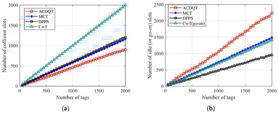
Figure 8.
Number of slots needed to identify tags: (a) collision slots; (b) idle (or go-on) slots.
As can be observed from Figure 8a, the proposed ACDQT algorithm takes the least number of collision slots to identify tags, while DPPS and MCT take more collision slots than ACDQT. CwT takes the most number of collision slots. This is because DPPS only splits colliding tags into two or four subsets. MCT splits tags into a fixed number of subsets, whereas the proposed ACDQT algorithm splits colliding tags into various numbers of subsets which is based on the number of consecutive colliding bits. Dynamically splitting colliding tags into smaller subsets, the number of collision slots is significantly reduced. Moreover, one can also observe that CwT takes much more collision slots than comparable algorithms. The main reason is that CwT always splits colliding tags into two subsets based on the first colliding bit position. The splitting process is slow, especially when the number of colliding tags is large. Therefore, CwT takes much more collision slots than others, and the gap becomes larger with the increase of tag number.
Figure 8b illustrates the number of idle slots needed to identify tags. As shown, ACDQT takes more idle slots than other protocols. In MCT, DPPS and ACDQT, colliding tags are divided into more subsets according to the number of consecutive colliding bits. Each subset corresponds to a slot in the new frame. One can not sense the number of tags in each subset. So, there are some idle slots, and the number of idle slots increases with larger frame length. In CwT, there are no idle slots, but the number of go-on slots is large. Although ACDQT takes more idle slots than comparable algorithms, it takes the least number of collision slots. As known, a collision slot takes much more time than an idle (or go-on) slots. Therefore, ACDQT will take a shorter time to identify tags than comparable protocols.
6.1.2. Number of Transmitted Message Bits
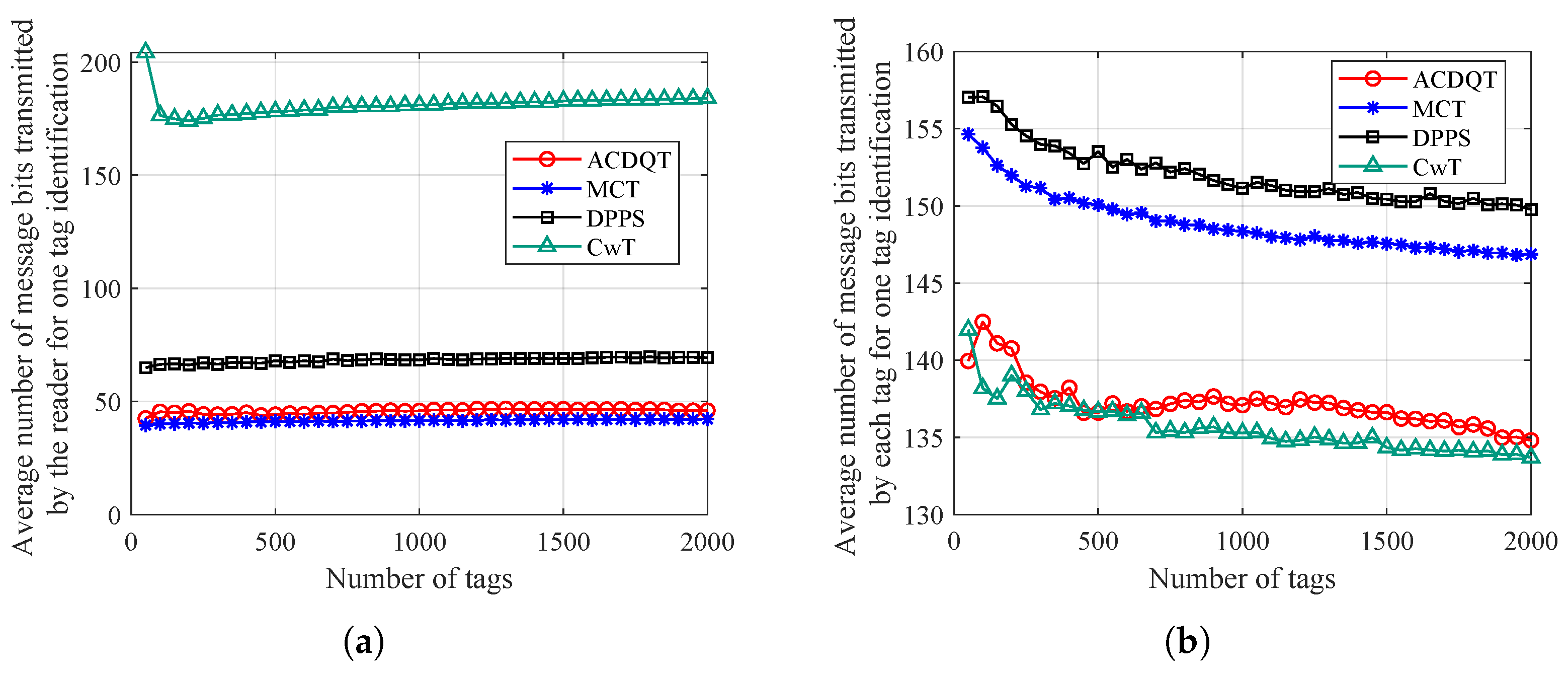
In the comparable algorithms, the frame structure and messages transmitted in each slot are different. Only the number of collisions and idle slots are not enough to evaluate the overall performance of these algorithms. The communication overhead of the RFID tag identification protocol refers to the number of message bits sent and received by the reader and tags during the identification process. The reader side overhead refers to the total number of message bits sent by the reader, and the tag side overhead refers to the total number of message bits in tag replies to the reader. In the simulation, a tag uses a 96-bit ID, and the reader needs to send two necessary commands during the identification process, i.e., the Query and Qrep commands. Since the identification time highly depends on the number of transmitted message bits, we give the comparison results of these algorithms in Figure 9.
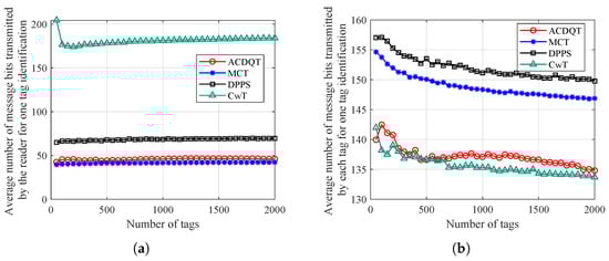
Figure 9.
Average number of message bits needed for one tag identification: (a) on the the reader side; (b) on the tag side.
The average number of command bits transmitted by the reader for one tag identification (i.e., communication overhead on the reader side) is shown in Figure 9a. It can be observed that ACDQT and MCT transmit smaller numbers of command bits on the reader side, and the communication overheads are stable at around 42 and 45 bits, respectively. This is because ACDQT and MCT both use a multi-branch tree structure. Compared with 180 bits of CwT and 68 bits of DPPS, communication overhead of ACDQT on the reader side is reduced by about 75% and 33.8%, respectively. This is because the proposed ACDQT protocol uses the number of consecutive collision bits to divide colliding tags into different groups in a new frame. In each frame, only one command and several commands are sent. This greatly saves the amount of command bits needed to send. Although the DPPS algorithm uses a command in each frame with two consecutive slots, the amount of command bits transmitted in each frame is small, but DPPS requires more frames to identify tags than ACDQT does. Thus, communication overhead on the reader side of DPPS is higher than that of ACDQT. In CwT, each slot comes with a command. With more slots, CwT transmits more command bits on the reader side than comparable algorithms.
Figure 9b illustrates the average number of message bits transmitted by the tag for one tag identification (i.e., communication overhead at each tag). As shown, a tag transmits fewer message bits in ACDQT and CwT than in the MCT and DPPS algorithms. This is because ACDQT takes the least number of collision slots. Thus, the response time for each tag is reduced accordingly. Secondly, a tag only needs to reply part of the ID information in each slot, which greatly reduces the number of message bits transmitted. Therefore, the communication overhead of each tag by implementing ACDQT is much lower than comparable algorithms. In CwT, a tag replies short messages in each slot. Therefore, although CwT takes more slots, the number of message bits transmitted by each tag is small.
6.1.3. Time Performance
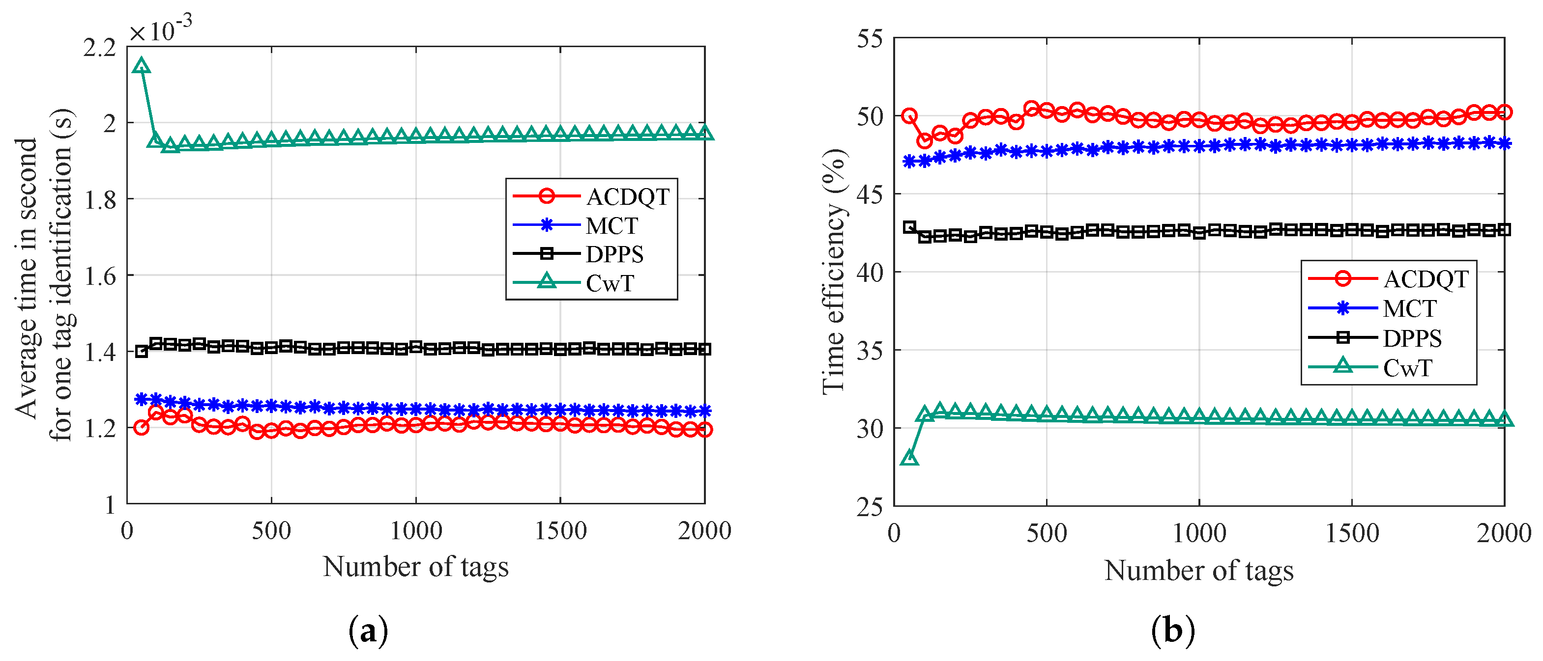
Finally, Figure 10 demonstrates the average time needed to identify one tag and the time efficiency. It should be noted that time efficiency is defined as the ratio of the time cost of a singleton slot to the average time needed to identify one tag. As one can observe in Figure 10a, the proposed ACDQT takes about 1.2 ms to identify a tag on average, whereas, MCT, DPPS and CwT take about 1.25 ms, 1.43 ms and 1.95 ms for one tag identification, respectively. Compared with MCT, DPPS and CwT, the time gain of ACDQT is around , and , respectively. It also demonstrates that although ACDQT takes more idle slots than other algorithms, the time saved by the smaller number of collision slots greatly improves the identification performance. Therefore, ACDQT takes much less time than the comparable algorithms. Moreover, in Figure 10b, one can also observe that the proposed ACDQT algorithm always has the highest time efficiency, which is about .
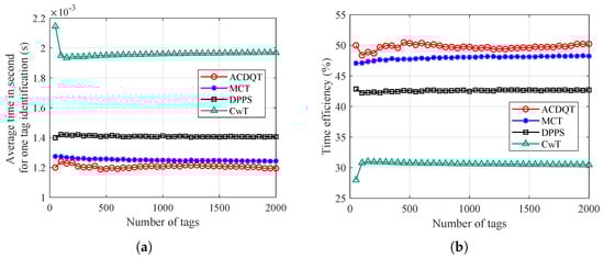
Figure 10.
Time performance: (a) average time for one tag identification; (b) time efficiency.
To sum up, in single-round identification (i.e., a static situation), the proposed ACDQT algorithm is superior to comparable algorithms in terms of fewer number of collision slots, lower communication overhead and shorter identification delay.
6.2. Fast-Moving Tag Identification
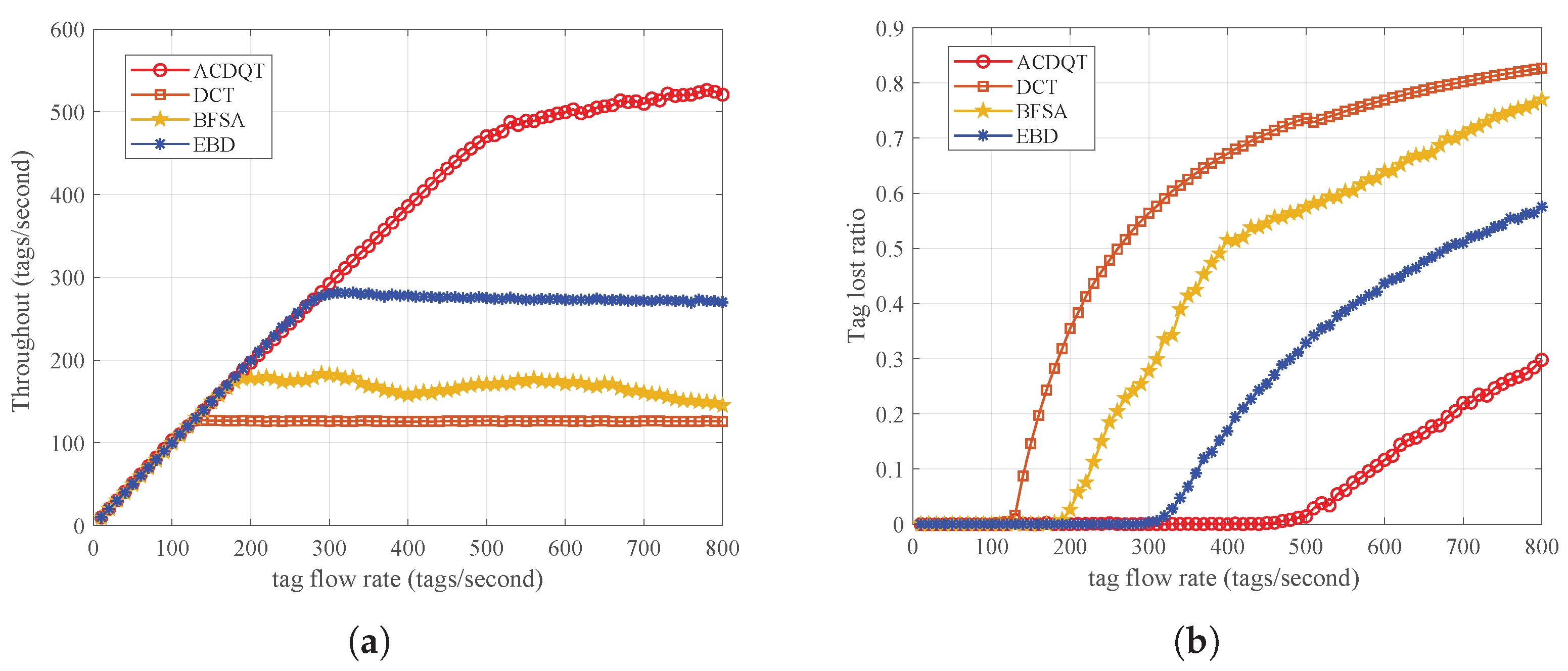
To evaluate tag recognition performance in a conveyor belt system, we measured from two metrics: throughput and tag lost ratio. Throughput refers to the number of tags recognized per unit of time, and the tag lost ratio is the ratio of tags that are not recognized (lost tags) after they move out of the reader’s reading range to the total number of tags passing through. The moving speed of the incoming tag flow of the system (termed tag flow rate) ranges from 0 to 800 tags/s, and the distances between tags are evenly distributed. The performance of ACDQT is compared with the three most related works dealing with moving tag situations, i.e., DCT [29], BFSA [26] and EBD [15]. Simulation results are illustrated in Figure 11.
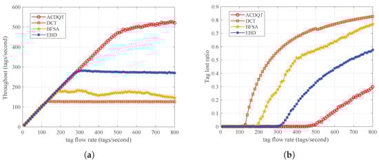
Figure 11.
Identification performance for fast-moving tags: (a) throughput; (b) tag lost ratio.
As can be observed from Figure 11a, the proposed ACDQT algorithm achieves much higher throughput than comparable algorithms, and the highest throughput is about 510 tags/s. Compared with EBD, BFSA and DCT, the throughput is improved by 20%, 85% and 140%, respectively. When tag flow rate is greater than 510, the throughput of ACDQT basically tends to be stable. However, when tag flow rate of BFSA is greater than 160, the fluctuation of throughput is relatively large, and it changes around 150. Since DCT directly repeats the identification process for fast-moving tags, it is limited by the performance of the tree splitting process. When new tags enter the reader’s reading range, they join the identification process immediately, which may collide with other participating tags. This greatly lowers the throughput in mobile systems. In EBD, newly arrived tags will participate in the identification process in the next round which relieves the collision situation. It also uses a new bit tracking strategy to accelerate the identification process in each round. Thus, its throughput is higher than DCT and BFSA but lower than ACDQT.
In Figure 11b, the tag lost ratio of ACDQT is 0 when tag flow moves slower than 470 tags/s, while in DCT, BFSA and EBD, the values are 120, 170 and 290, respectively. After these points, the tag lost ratio increases with the tag flow rate. This is because with the tag flow rate increasing, the reader does not have enough time to identify all tags in the current round before they move out of reading range. In this situation, some tags may leave unrecognized after they move out of the reader’s reading range, resulting in a lost tag. With larger tag flow rate, the lost tag situation becomes worse. Nevertheless, the proposed ACDQT has much higher throughput and a lower tag lost ratio than comparable algorithms, which is more suitable to be implemented in fast-moving RFID systems. Finally, Table 7 lists the overall results of the comparable algorithms in single round and fast-moving situations. Note that the bold values refer to the best performance in each group, and the results are in accordance with these in Figure 8, Figure 9 and Figure 10.
Table 7.
Simulation results of the comparable algorithms in single round and fast-moving situations.
7. Conclusions
In this paper, we established an identification model for mobile RFID systems and proposed an ACDQT algorithm for fast-moving tag identification. In ACDQT, a new multi-round admission control mechanism is designed to admit reasonable tags participating in each reading round. Next, a novel dynamic query tree strategy was developed to quickly identify tags in each round. Theoretical analysis was conducted to calculate the number of slots and average time needed to identify tags in a single round. We conducted numerous simulations to evaluate the identification performance in a single round and in multiple rounds in conveyor belt systems. The performance of ACDQT is also compared with the most related benchmark works. Simulation results demonstrate that ACDQT outperforms existing works in diverse situations. In our future work, we will consider using a machine learning method for tag flow estimation in the admission control process.
Author Contributions
Methodology, J.P. and N.Z.; conceptualization, L.Z. and L.L.; formal analysis, M.F.; validation, Q.H. and J.X. All authors have read and agreed to the published version of the manuscript.
Funding
This research was funded by the National Natural Science Foundation of China (No. 61902182), the Natural Science Foundation of Jiangsu Province of China (No. BK20190409), the Aeronautical Science Foundation of China (No. 2016ZC52029), Qing Lan Project of Jiangsu Province of China, and China Postdoctoral Science Foundation (No. 2019TQ0153) and the Future Network Scientific Research Fund Project (FNSRFP-2021-ZD-4).
Institutional Review Board Statement
Not applicable.
Informed Consent Statement
Not applicable.
Data Availability Statement
No public data link are privided in this work.
Conflicts of Interest
The authors declare no conflict of interest.
References
- Elbasani, E.; Siriporn, P.; Choi, J.S. A Survey on RFID in Industry 4.0; part of EAI/springer innovations in communication and computing book series; Springer: Cham, Switzerland, 2019; pp. 1–16. [Google Scholar]
- Landaluce, H.; Arjona, L.; Perallos, A.; Falcone, F.; Angulo, I.; Muralter, F. A review of IoT sensing applications and challenges using RFID and wireless sensor networks. Sensors 2020, 20, 2495. [Google Scholar] [CrossRef] [PubMed]
- Klair, D.K.; Chin, K.-W.; Raad, R. A survey and tutorial of RFID anti-collision protocols. IEEE Commun. Surv. Tutorials 2010, 12, 400–421. [Google Scholar] [CrossRef]
- Jia, X.; Feng, Q.; Ma, C. An efficient anti-collision protocol for RFID tag identification. IEEE Commun. Lett. 2010, 14, 1014–1016. [Google Scholar] [CrossRef]
- Landaluce, H.; Perallos, A.; Onieva, E.; Arjona, L.; Bengtsson, L. An energy and identification time decreasing procedure for memoryless RFIDtag anti-collision protocols. IEEE Trans. Wireless Commun. 2016, 15, 4234–4247. [Google Scholar] [CrossRef]
- Zhang, L.; Xiang, W.; Tang, X.; Li, Q.; Yan, Q. A Time- and Energy-Aware Collision Tree Protocol for Efficient Large-Scale RFID Tag Identification. IEEE Trans. Ind. Informatics 2018, 14, 2406–2417. [Google Scholar] [CrossRef]
- Su, J.; Sheng, Z.; Wen, G.; Leung, V.C.M. A time efficient tag identification algorithm using dual prefix probe scheme (DPPS). IEEE Signal Process. Lett. 2016, 23, 386–389. [Google Scholar] [CrossRef]
- Su, J.; Sheng, Z.; Liu, A.X.; Han, Y.; Chen, Y. A group-based binary splitting algorithm for UHF RFID anti-collision systems. IEEE Trans. Commun. 2020, 68, 998–1012. [Google Scholar] [CrossRef]
- Roberti, M. Wal-Mart begins RFID rollout. RFID J. 2004, 75–77. Available online: https://www.rfidjournal.com/wal-mart-begins-rfid-rollout (accessed on 30 April 2004).
- Caccami, M.C.; Amendola, S.; Occhiuzzi, C. Method and system for reading RFID tags embedded into tires on conveyors. In Proceedings of the 2019 IEEE International Conference on RFID Technology and Applications (RFID-TA), Pisa, Italy, 25–27 September 2019; pp. 141–144. [Google Scholar]
- Badriev, A.; Makarova, I.; Buyvol, P. The RFID system for accounting and control of truck tires with two-step identification: A case study. In Proceedings of the 2020 13th International Conference on Developments in eSystems Engineering (DeSE), Liverpool, UK, 14–17 December 2020; pp. 100–104. [Google Scholar]
- Vales-Alonso, J.; Bueno-Delgado, M.V.; Egea-Lopez, E.; Alcaraz-Epsin, J.J.; Garcia-Haro, J. Markovian Model for Computation of Tag Loss Ratio in Dynamic RFID Systems. In Proceedings of the 5th European Workshop on RFID Systems and Technologies, VDE, Bremen, Germany, 16–17 June 2009; pp. 1–8. [Google Scholar]
- Gotfryd, M.; Pawlowicz, B. Modeling of a dynamic RFID system. In Proceedings of the 2013 IEEE Symposium on Computers and Communications (ISCC), Split, Croatia, 7–10 July 2013; pp. 747–752. [Google Scholar]
- Liu, J.; Feng, Q. A blocking collision tracking tree algorithm in mobile RFID systems. In Proceedings of the 2017 Progress in Electromagnetics Research Symposium, St. Petersburg, Russia, 22–25 May 2017; pp. 22–25. [Google Scholar]
- Zhang, L.; Xiang, W.; Tang, X. An efficient bit-detecting protocol for continuous tag recognition in mobile RFID systems. IEEE Trans. Mob. Comput. 2018, 17, 503–516. [Google Scholar] [CrossRef]
- EPCglobal. EPCTM Radio-Frequency Identity Protocols Generation-2 UHF RFID Specification for RFID Air Interface Protocol for Communications at 860 MHz–960 MHz, Version 2.0.1 Ratified. 2015. Available online: http://www.gs1.org/sites/default/files/docs/epc/Gen2_Protocol_Standard.pdf (accessed on 1 April 2015).
- Vales-Alonso, J.; Bueno-Delgado, V.; Egea-Lopez, E. Multi-frame maximum-likelihood tag estimation for RFID anticollision protocols. IEEE Trans. Ind. Informatics 2011, 7, 487–496. [Google Scholar] [CrossRef]
- Myung, J.; Lee, W.; Shih, T.K. An Adaptive Memoryless Protocol for RFID Tag Collision Arbitration. IEEE Trans. Multimed. 2006, 8, 1096–1101. [Google Scholar] [CrossRef]
- Myung, J.; Lee, W.; Srivastava, J.; Shih, T.K. Tag-Splitting: Adaptive Collision Arbitration Protocols for RFID Tag Identification. IEEE Trans. Parallel Distrib. Syst. 2007, 18, 763–775. [Google Scholar] [CrossRef]
- Su, J.; Chen, Y.; Sheng, Z.; Huang, Z.; Liu, A.X. From M-ary query to bit query: A new strategy for efficient large-scale RFID identification. IEEE Trans. Commun. 2020, 68, 2381–2393. [Google Scholar] [CrossRef]
- Liu, B.; Su, X. An anti-collision algorithm for RFID based on an array and encoding scheme. Information 2018, 9, 63. [Google Scholar] [CrossRef]
- Hailemariam, Z.L.; Lai, Y.-C.; Jayadi, R.; Chen, Y.H. A knowledge-based query tree with shortcutting and couple-resolution for RFID tag identification. Comput. Commun. 2020, 160, 779–789. [Google Scholar] [CrossRef]
- Saranga, V.; Devarapalli, M.R.; Radhakrishnan, S. A framework for fast RFID tag reading in static and mobile environments. Comput. Netw. 2008, 52, 1058–1073. [Google Scholar] [CrossRef]
- Vales-Alonso, J.; Egea-Lopez, E.; Delgado, M.V.B. Analysis of tag lost ratio in dynamic RFID systems. Int. J. Technol. 2010, 2, 135–154. [Google Scholar]
- Alcaraz, J.J.; Egea-Lopez, E.; Vales-Alonso, J.; Garcia-Haro, J. Dynamic system model for optimal configuration of mobile RFID systems. Comput. Netw. 2011, 55, 74–83. [Google Scholar] [CrossRef]
- Alcaraz, J.J.; Vales-Alonso, J.; Garcia-Haro, J. RFID reader scheduling for reliable identification. IEEE Trans. Autom. Sci. Eng. 2013, 10, 816–827. [Google Scholar] [CrossRef]
- Kang, L.; Qian, C.; Ni, L. RSAA: Reliable splitting aware ALOHA to capture passing tags. In Proceedings of the 2012 IEEE 9th International Conference on Mobile ad-hoc and Sensor Systems (MASS 2012), Las Vegas, NV, USA, 8–11 October 2012; pp. 38–46. [Google Scholar]
- Zhu, W.; Cao, J.; Chan, H.C.B.; Liu, X.; Raychoudhury, V. Mobile RFID with a high identification rate. IEEE Trans. Comput. 2014, 63, 1778–1792. [Google Scholar] [CrossRef]
- Jia, X.; Bolic, M.; Feng, Y.; Gu, Y. An efficient dynamic anti-collision protocol for mobile RFID tags identification. IEEE Commun. Lett. 2019, 23, 620–623. [Google Scholar] [CrossRef]
- Yu, J.; Chen, L. From static to dynamic tag population estimation: An extended kalman filter perspective. In Tag Counting and Monitoring in Large-Scale RFID Systems; Springer: Berlin/Heidelberg, Germany, 2019; pp. 43–75. [Google Scholar]
- Lin, Q.; Yang, L.; Duan, C.; Liu, Y. Revisiting reading rate with mobility: Rate-adaptive reading of COTS RFID systems. IEEE Trans. Mob. Comput. 2019, 18, 1631–1646. [Google Scholar] [CrossRef]
- Chen, Y.; Feng, Q. A Collision Avoidance Identification Algorithm for Mobile RFID Device. IEEE Trans. Consum. Electron. 2019, 65, 493–501. [Google Scholar]
- Hush, D.; Wood, C. Analysis of tree algorithms for RFID arbitration. In Proceedings of the 1998 IEEE International Symposium on Information Theory, Cambridge, MA, USA, 16–21 August 1998; pp. 107–117. [Google Scholar]
- Kaplan, M.A.; Golko, E. Analytic properties of multiple access trees. IEEE Trans. Inf. Theory 1985, 31, 255–263. [Google Scholar] [CrossRef]
- Feller, W. An Introduction to Probability Theory and Its Applications, 3rd ed.; John Wiley: Hoboken, NJ, USA, 1968; Volume 1. [Google Scholar]

Disclaimer/Publisher’s Note: The statements, opinions and data contained in all publications are solely those of the individual author(s) and contributor(s) and not of MDPI and/or the editor(s). MDPI and/or the editor(s) disclaim responsibility for any injury to people or property resulting from any ideas, methods, instructions or products referred to in the content. |
© 2023 by the authors. Licensee MDPI, Basel, Switzerland. This article is an open access article distributed under the terms and conditions of the Creative Commons Attribution (CC BY) license (https://creativecommons.org/licenses/by/4.0/).