Featured Application
In this work, the transient response of a single-degree-of-freedom (SDOF) system with a tubular linear eddy current damper (TLECD) under shock excitation is calculated and analyzed. Moreover, to achieve the best design and performance assessment of the structural shock vibration control by the TLECD, this study introduces the shock response spectrums (SRSs) and a straightforward design flowchart of the TLECD for its mechanical characteristics.
Abstract
The nonlinear dynamic characteristic of a tubular linear eddy current damper (TLECD) and the transient responses to shock excitations of a single-degree-of-freedom (SDOF) system with the TLECD are studied. First, the nonlinear force-velocity relationship of the TLECD is discussed using the finite element simulation and mathematical model fitting. Next, the influences of three forms of shock excitation and various mechanical parameters of the TLECD on shock vibration control of an SDOF system with the TLECD are investigated. Moreover, for the SDOF systems with the TLECD or the nonlinear fluid viscous dampers (FVD) at the same maximum displacement and maximum damper force, the time to reach the maximum displacement, the time to reach one-third of the maximum displacement, the energy input of the external loading, and the energy dissipation of dampers are analyzed and compared. Finally, the shock response spectrums (SRSs) of the SDOF system and the design flowchart for the TLECD are presented to provide a reference for shock vibration control of the SDOF system with the nonlinear TLECD and the design of TLECDs. The results show that there is an optimal dimensionless critical relative velocity that minimizes the dimensionless maximum damping force for reaching the target maximum displacement, and compared to the FVD, the TLECD greatly shortens the time to reach one-third of the maximum displacement.
1. Introduction
Structural vibration control methods and devices have been well-developed to suppress vibration [1,2,3]. Unlike force loadings with a relatively long duration, impulse loadings are a special form of loading that can be applied to a structure in a very short period. In general, when the ratio of the duration of loading to the natural period , the loading can be defined as an impulse [4,5]. In reality, impulsive loadings can be generated from many sources, including free-fall impacts, collisions, explosions, short-duration pulse-type seismic excitations, aircraft landing, braking loads, and many more. Although the duration of impulse loadings is relatively short, the peak forces exerted on the structure are usually quite high. As a result, the loadings can generate high responses and damage the structure consequently. This means that the design of the structure or the corresponding measures to prevent shock is crucial. In order to alleviate high responses caused by shock pulses, a wide range of control devices have been proposed and analyzed. Based on the stability maximization criterion [6], various types of dynamic vibration absorbers have been designed to decay transient responses [7,8,9]. Moreover, some nonlinear devices [10] and semi-active [11] or active control systems [12,13] were also proposed for shock vibration control. Compared to the complicated vibration control system, it is simpler and more direct to exert resistance forces on the structure by dampers to reduce structural transient responses caused by impulsive loadings. Hence, it is necessary to calculate and analyze structural transient responses under shock excitation. Responses of the structure without dampers or with just linear dampers can be easily calculated when subjected to simple loading forms, such as sinusoidal loading and rectangular loading [5,14]. Moreover, the responses of the structure with nonlinear fluid viscous dampers (FVDs) under impulsive loadings have been analyzed [15,16].
Recently, the eddy current damper (ECD) has gained growing interest in the field of structural vibration suppression [17,18] and auxiliary braking systems [19]. The eddy current damper mainly consists of a stator and a relatively movable part (i.e., permanent magnets and the conductor), and the damping force is actually the Lorentz force generated from the conductor by cutting the magnetic lines of flux. If the conductor is replaced by the closed conductive coil, the ECDs will transfrom into electromagnetic dampers [20]. In the ECD, the permanent magnets (PMs) and the conductor are contactless, which implies that wear and fatigue can be avoided to result in less maintenance and a longer lifetime. In contrast to the conventional FVD, another merit of the ECD is that it does not need a working fluid, and thus, the ECD does not suffer from fluid-related issues, including leaks, degradation, and high temperature. In eddy current tuned mass dampers (ECTMDs), the ECD can function as a planar damping component [17,18,21], or it can directly act on the structure in the forms of a rotary type [22,23] and linear type [24]. When the relative velocity between the PMs and the conductor is not high, the damping force of the ECD is nearly linear with the change in velocity [21]. This usually happens in the ECD without speed amplification devices such as the EC-TMD, or when the external excitations are gentle. However, if the relative velocity is amplified by the ball-screw mechanism [25] and rack and gear [26], or when external excitations are intense as mentioned above, the relative velocity can be quite high and the ECD shows strong nonlinearity in the force-velocity relationship due to the induced magnetic field resisting original magnetic field [27].
The tubular linear eddy current damper (TLECD) has been applied in a wide range of vibration isolation systems such as precision machinery and vehicle suspension systems [28,29,30], and it has excellent application prospects in structural vibration suppression under impulsive excitation [31,32,33]. In contrast to the linear plate ECD mainly used in the EC-TMD, the TLECD has no transverse end effect, leading to a higher utilization rate of PMs and energy consumption density. In addition, different from rotary ECDs using mechanical transmission [25,26], the TLECD is simpler, compacter, and safer, especially when the structure is under impulsive loadings.
2. Tubular Linear Eddy Current Damper with Halbach Array (TLECD-HA)
2.1. Configuration of the TLECD-HA
The TLECD’s longitudinal cross-section is shown in Figure 1. The Halbach permanent magnet array, which has been demonstrated to improve the performance of ECDs, has been employed [32,34]. The Halbach array has been widely used in the fields of permanent magnet motors [35], nuclear magnetic resonance [36], and eddy current braking [37]. However, for the application of the TLECD, the form of a combination of PMs and pole shoes is usually a better choice because of the difficulty to manufacture magnetic rings with radial magnetization. Figure 1 depicts that the tubular linear eddy current damper with Halbach array (TLECD-HA) is mainly made of PMs, a conductor cylinder, back irons for the conductor cylinder and PMs, and two end connections. One connection is connected to the conductor by an end cap, and another is connected to the PMs by a shaft. As a result, the relative motion between the structures results in the relative motion between the PMs and the conductor cylinder, which generates the damping force.
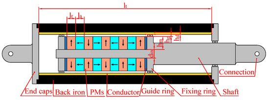
Figure 1.
Longitudinal cross-section of the TLECD-HA.
2.2. Force-Velocity Relationship of the TLECD
The change of damping force of the ECD with the variation of relative velocity is strongly nonlinear in the condition of high velocity, whereas this relationship can be nearly linearized at low velocity. A semi-empirical and semi-analytic model proposed by Wouterse [27] can well represent the trait of damping force in the ECD, and its applicability has been proved in ball screws with high energy density type axial eddy current damper (BS-ECD) [38]. The eddy current damping force represented by the parametric Wouterse’s model has the following form:
where is the peak damping force for the ECD, and is the critical relative velocity when the peak damping force is reached. It is noticeable that these two mechanical model parameters are determined by the physical design parameters of the TLECD-HA. Figure 2 depicts the force-velocity relationship obtained from simulations using the finite element method (FEM) and the fitting curve acquired using Wouterse’s semi-empirical model. It can be noted that Wouterse’s model is still applicable to the TLECD-HA. In the following modeling and response analysis, the focus is on the mechanical characteristic of the TLECD instead of its physical configuration, and therefore, the TLECD is simply referred to as the ECD.

Figure 2.
Fitting curve versus FEM results.
3. Analytical Model for Transient Responses of an SDOF System with the ECD
3.1. Shock Excitation
A shock pulse can be used to describe shock excitation, usually in terms of the time history of excitation of acceleration, velocity, displacement, or force. Although shock situations are quite complicated in practice, idealized and simple forms of the time history of shock excitation are commonly used to approximate practical situations. Figure 3 shows the common idealized forms of shock excitation. Various kinds of shock excitation are determined by different shapes, peak magnitudes, and durations.
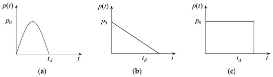
Figure 3.
Three types of idealized shock excitation: (a) Half-cycle sine; (b) Initial peak triangular; (c) Rectangular.
In this study, the common acceleration time history is considered to represent shock excitation, and three profiles of acceleration are considered, including the half-cycle sine, initial peak triangular, and rectangular. These three types of idealized shock excitation are mathematically expressed as:
Half-cycle sine shock excitation:
Initial peak triangular shock excitation:
Rectangular shock excitation:
3.2. Equation of Motion
As the SDOF system can reflect relevant dynamic characteristics of the relevant multi-degree-of-freedom (MDOF) system in a specific movement pattern, it is a common perception in both the design and retrofit of structures to simulate the latter by creating an equivalent or approximate one for the former. Therefore, in the initial design stage of a supplement damping system for a structure, the MDOF system could be simplified into an SDOF. Figure 4 depicts an SDOF system with the ECD subjected to external loading.
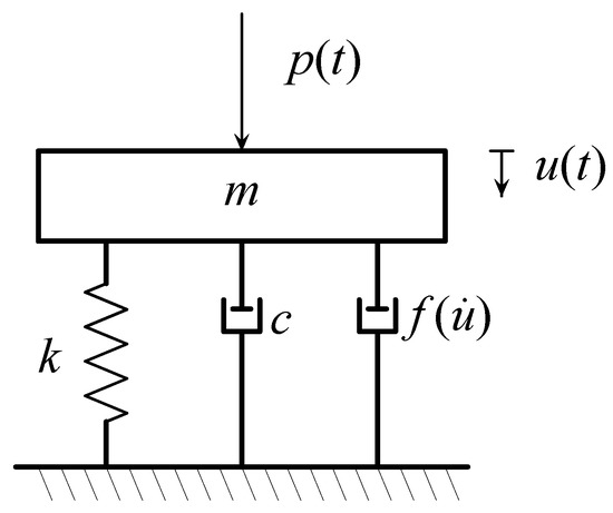
Figure 4.
Sketch map of the SDOF system with the ECD subjected to external loading.
The equation of motion for the SDOF system (with a mass m and stiffness k) equipped with an ECD subjected to shock excitation can be expressed as:
In this equation, the upper dots represent time derivatives; and , , and represent the natural frequency, natural damping ratio, and shock loading, respectively. The system’s response, , is determined by the external excitation, as evidenced by the equation’s nonlinearity.
By integrating the individual force terms in (5) over the entire relative displacement history, the energy representation can be formed as:
where
The left-hand-side of (6) represents the kinetic energy of the mass (), the dissipative energy caused by inherent damping in the structure (), the dissipative energy caused by the extra damper (ED), and the elastic strain energy ( These energies can balance the input energy () imposed on the structure by external forces. In this study, the shock excitation is considered as shock acceleration and represents the shock excitation. It depends on three parameters including the maximum value , duration , and shape.
It is easy to numerically solve Equation (5). The Newmark-β average method is an unconditionally stable integration method and it is used in this study to calculate the transient shock-excited response of the SDOF system with the ECD. In order to obtain the accurate shock-excited response, a quite small time-step of shock loading ) is taken in the step-by-step solution of this study.
4. Transient Response Analysis
4.1. Parameters of the Structure, Shock Excitation, and TLECD
The effects of the impulse trait of shock excitation and mechanical parameters of the ECD on shock vibration control are studied using the SDOF system with the ECD, as shown in Figure 4. The response of the SDOF system with nonlinear FVD subjected to shock excitation has been analyzed by Narkhede [15]. The same structural parameters in [15] are also adopted in this study as shown in Table 1.

Table 1.
Structure parameters.
The above example structure is certain and maybe not applicable in typical Civil Engineering structures. However, the later shock response spectrum (SRS) is dimensionless, and therefore, it is applicable for structures with a wide range of frequencies regardless of whether they are rigid or flexible. As long as the ratio of the shock load excitation duration to the structure’s natural period is within a fine scope, the shock can still be considered an impulse. Moreover, the dimensionless mechanical parameters of the ECD are also adopted to ensure they are widely applicable. The dimensionless maximum damping force and the dimensionless critical relative velocity can be given as:
4.2. Time-History Response
Under a half-cycle sine shock, the time-history responses for displacement, velocity, acceleration, and energy of the SDOF system without a damper and with ECDs are shown in Figure 5. The parameters of the half-cycle sine shock are shown in Table 2. From these time histories, it can be observed that there is a dramatic reduction in the peak responses, including the maximum displacement, maximum velocity, maximum acceleration, and the time for decaying to stabilization of the SDOF system when equipped with an ECD. The peak responses and the time to reach the peak responses are also observed to decrease when the dimensionless critical relative velocity decreases or the peak dimensionless damping force increases.
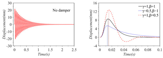
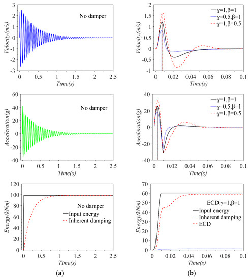
Figure 5.
Time−histories for displacement, velocity, acceleration, and energy of the SDOF system subjected to half-cycle sine shock: (a) Without damper; (b) With an ECD.
Table 2.
Adjusted acceleration loads.
4.3. Influence of Shock Impulse Characteristics and ECD Mechanical Parameters
In this section, various peak responses are mainly analyzed instead of the whole-time histories of the SDOF system with various ECDs when subjected to different forms of impulsive excitation.
Maximum structural deformation is typically a crucial design criterion in the design of dampers for shock vibration control, and the transient response analysis is useful for the performance evaluation of ECDs. The intended maximum displacement of the SDOF system with the ECD is, therefore, set to be approximately 15% of the intended maximum displacement of the case without a damper. In this section, different values of the dimensionless critical relative velocity have been considered in the peak response analysis, and the dimensionless maximum damping force is an independent design variable obtained through multiple iterations to reach the intended maximum displacement. For achieving the target maximum displacement, other responses are discussed, including the maximum damper force , the time to maximum displacement , and the time required for decaying to one-third of the intended maximum displacement . The last item is approximately 5% of the maximum displacement of the system without a damper, and the reason to discuss it is that sometimes it is the threshold value to use the devices repeatedly in some cases.
Meanwhile, as mentioned before, shock excitation is determined by its maximum value, duration, and shape. Figure 3 depicts the three types of shock excitation used in this section including the rectangular shock, initial peak triangular shock, and half-cycle sine shock. The duration of each shock is set to be 10 milliseconds so that the ratio of the shock duration to the period of the structure , which satisfies the definition of an impulse. For the peak acceleration of each shock, it is adjusted so that the impulse is the same for each shock. Given that the peak force for each shock is , the impulses for the three forms of shock excitation are , , and . Similarly, the corresponding peak acceleration is adjusted as shown in Table 2.
However, when the critical relative velocity and the maximum damping force are dimensionless, the peak acceleration values of the three forms of loadings are considered the same at 30 g to reflect the same impulse.
Figure 6 shows the required dimensionless damping force of the ECD and responses of the SDOF system with an ECD with a varying dimensionless critical relative velocity subjected to half-cycle sine, initial peak triangular, and the rectangular shock when reaching the target maximum displacement. From Figure 6a, it can be seen that there is a minimal dimensionless maximum damping force for all shock loadings, and the system with the ECD subjected to rectangular shock always requires the minimum value. In general, the larger maximum damping force of the ECD represents a larger dimension and a higher cost, and therefore, the optimal value of the dimensionless maximum damping force is significant. Similarly, a minimal time of the target maximum displacement can also be noted in Figure 6c, and the values are always the largest and the smallest for rectangular and initial peak triangular shock, respectively. This implies that the ECD can be designed for optimal control when reaching the target maximum displacement.
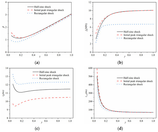
Figure 6.
Parameter of the ECD and responses of the SDOF system with the ECD subjected to three forms of shock excitation: (a) The dimensionless damping force of the ECD; (b) The peak damper force; (c) The time to reach the intended maximum displacement; and (d) The time to decay to one-third of the intended maximum displacement.
It is also observed that the differences between the half-cycle sine shock and the initial peak triangular shock in Figure 6a,b,d are quite small for dimensionless critical relative velocity from 0.2 to 1. This means that when the dimensionless critical relative velocity of the ECD is between 0.2 and 1, the dynamic properties of the system with the ECD subjected to these two forms of shock loading are comparable.
4.4. Comparison of the ECD and FVD in Shock Vibration Control
In addition to the influence of the mechanical parameters of the ECD on structural responses, performance evaluation and comparison of ECDs with FVDs in shock vibration control are also necessary, since the latter is the most widely used energy dispassion device. The force-velocity relationship of the FVD can be expressed as (14), in which and are the damper constant and the damper exponent, respectively. However, different from the steady-state response of the structure under constant harmonic excitation [38], the concept of equal energy dissipation for the structural response during impulsive loading is pointless, so it is hard to directly compare the performance of the FVD and ECD for shock vibration control. As a result, by introducing two target responses, the maximum displacement and the maximum damper force (which are significant in structural responses), the mechanical parameters of the FVD (the damper constant and the damper exponent) and ECD (the maximum damping force and the critical relative velocity) can be determined. In this section, the target maximum displacement is set to be the same as that in Section 4.3. Given that the damper exponent of the FVD α usually ranges from 0.35 to 1.00 for vibration control [39], the target maximum damper force of the ECD is taken to be the same as that of the FVD when the damper exponent is 0.5 and when the maximum displacement of the SDOF system with the FVD reaches the target maximum displacement. Because of the same maximum displacement and damper force, after determining the mechanical parameters of the ECD and the FVD, other responses, including the time of maximum displacement and the time required for decaying to one-third of the target maximum displacement, will be discussed.
Figure 7 shows the comparison of the two time indexes and two energy indexes when the system is equipped with the FVD and the ECD, respectively. It can be observed from Figure 7a,b that at the same maximum displacement and damper force, the SDOF system with the ECD requires a slightly longer time to reach the target maximum but much less time to decay to one-third of the target maximum displacement. This means that the ECD is more advantageous in some design cases where the structure requires to return to the initial state. From an energy perspective, Figure 7c,d illustrates that compared to the FVD, the ECD slightly reduces the energy input of the system and also dissipates less energy. This is particularly true when the system is subjected to an initial peak triangular shock. The displacement time history of the SDOF systems with an ECD and an FVD subjected to half-cycle sine shock is shown in Figure 8a, and the differences in the two time indexes between the ECD and the FVD can be clearly seen. From Figure 8b, it can be observed that when the velocity is less than 0.27 m/s, the ECD provides the lower damper force, although it provides the higher damping force when the velocity is higher than 0.27 m/s.
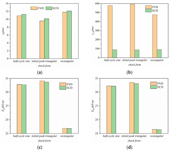
Figure 7.
Comparison of the responses of the SDOF system with the FVD or the ECD: (a) Time of the target maximum displacement; (b) Time required for decaying to one-third of the target maximum displacement; (c) Energy input from the external loading; and (d) Energy dissipation by the damper.
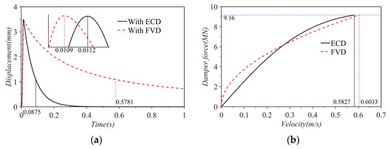
Figure 8.
Responses of the SDOF systems with an ECD or FVD subjected to half-cycle sine shock at the same maximum displacement and damper force: (a) Displacement time history; and (b) Force-velocity relationships of the ECD and the FVD within the time history.
Moreover, the shock vibration control performance of the ECD and the FVD under seismic excitation is also considered in this study. Figure 9 shows the acceleration time histories of the EW El Centro wave, and Figure 10 shows the displacement time histories of the SDOF system in three conditions, i.e., without damper, with an FVD, and with an ECD. In this case, the damper constant and the damper exponent of the FVD are 12 kN·s/m and 0.7, respectively. The parameters of the ECD are determined by the design method in [38], with and , where is the maximum velocity of this SDOF system with a FVD under seismic excitation. Considering that the power spectral densities of the ground motions are larger between 1–2 Hz, the natural period of the structure is adjusted to 10 s to meet the definition of impulsive loading. Other structural parameters are set to be the same as those in Section 4.1. As can be seen from Figure 10, the ECD can effectively reduce structural displacement, and it is better than the FVD in terms of displacement attenuation.
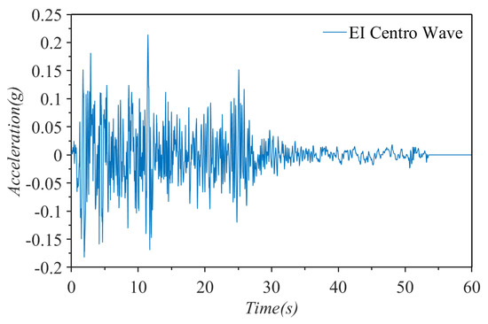
Figure 9.
Time−histories of ground motion.
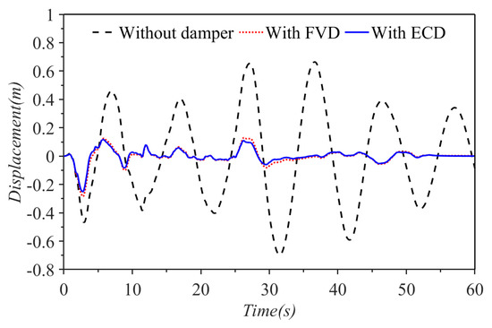
Figure 10.
Time−histories of structural displacement under the three conditions.
4.5. Shock Response Spectrum
The peak responses, such as structural displacement, damper force, elastic force, and time to reach maximum displacement, are usually of the most concern during the design. The SRS is a graph of the maximum response of the SDOF system as a function of its natural frequency in response to the loaded impulsive excitation [40]. It has been widely used for the prediction of structural responses or the design of related structural parameters to reach the target response.
Figure 11 shows the SRSs of the SDOF system under half-cycle sine shock, and represents the changes in peak responses with the ratio of duration to the natural period of the system for various mechanical parameters of the ECD. The SRSs of the structure subjected to other forms of shock impulse can be obtained by the same method, and therefore, not all of them are listed here. The maximum elastic force can be calculated by the known maximum displacement and the stiffness of the system k. Based on the SRS, the peak responses of a certain system with certain design parameters of the ECD can be predicted, or the parameters of the system and the ECD can be designed for target peak responses. Because of the dimensionless characteristic, the SRS is applicable to a wide range of systems.
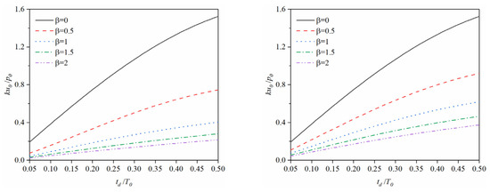
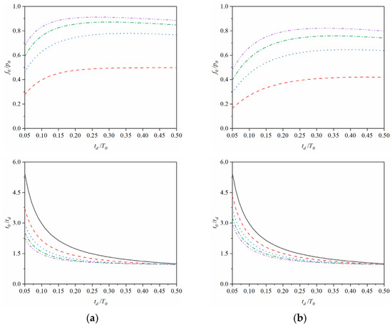
Figure 11.
Maximum responses of the SDOF system with various ECDs under half-cycle sine shock excitation: (a) ; and (b) .
It can be noted that the dimensionless maximum displacement increases with the increase of the ratio of the shock duration to the natural period of the system. In addition, the dimensionless time of the maximum displacement has an opposing trend, but the gap between different dimensionless critical relative velocities and maximum damping forces reduces as the dimensionless shock duration increases. The dimensionless maximum damper force increases with the increase of dimensionless shock duration but remains stable when the ratio of shock excitation duration to the structure’s natural period is larger than 0.2.
5. Design of the TLECD
5.1. Influence of Physical Parameters on the Force-Velocity Relationship of the TLECD
From Wouterse’s model in Section 2, it is clear that the force-velocity relationship of the TLECD is determined by the maximum damping force and the critical relative velocity, and they also have been proven to have a great influence on the peak responses of the SDOF system in Section 4.5. As a result, the design of the TLECD-HA for these two mechanical parameters is crucial for shock vibration control of the structure with TLECDs. The array type and size of the PMs, their remanence, the air gap, the conductivity of the conductor, and conductor thickness are just a few physical design parameters of the TLECD that affect these two mechanical parameters in a practical model [31,32,41]. Some of these physical design parameters have a significant impact on both mechanical parameters, while others mainly affect one of them.
From the electromagnetic finite element analysis for the TLECD using the COMSOL Multiphysics 5.6 software, the influence of some physical design parameters on the force-velocity relationship of the TLECD can be seen in Figure 12. It can be seen that the radial height of the air gap, the number of PM rings, the radial height of PM rings, and the radial inner diameter of PM rings only affect the maximum damping force, whereas the conductivity of the conductor just influences the critical relative velocity. In addition, the radial height of the conductor determines both mechanical parameters. As a result, the design of a practical ECD can be mainly divided into two parts: one design part for one mechanical parameter, and another design part for another mechanical parameter. Different from the idealized influence in Figure 12, more realistic factors are expected to be taken into account. For example, the size of the permanent magnet and the conductor should be within an appropriate range, and there is a bottom limit on the height of the air gap due to possible contact. Moreover, under different processing methods and heat treatment conditions, the conductivity of copper alloy or aluminum alloy can be adjusted from 6%IACS (International Annealed Copper Standard) to 95%IACS, but the conductivity of the commonly used metals or metal alloys is fixed. More practical considerations are not mentioned here.
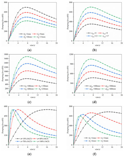
Figure 12.
Influence of physical design parameters of the ECD on its constitutive behavior: (a) Damping force versus the radial height of air gap; (b) Damping force versus the number of PM rings; (c) Damping force versus the radial height of PM rings; (d) Damping force versus the radial inner diameter of PM rings; (e) Damping force versus the conductivity of conductor; and (f) Damping force versus the radial height of conductor.
5.2. Design Example
Aimed at the force-velocity relationship of the TLECD and given the practical factors, a simplified design flow chart for the TLECD can be seen in Figure 13, where the design begins with the input of the dimensionless maximum damping force, the dimensionless critical relative velocity, and the parameters of the structure and the loading, and it ends if the error of the maximum damping force is less than 1%.
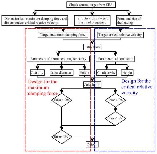
Figure 13.
Design flow chart for the TLECD.
Based on the flowchart in Figure 13, a design example is given. The parameters of the structure and the loading are taken to be the same as the structural traits in Section 4.1 and the half-cycle sine shock in Section 4.3, respectively. The dimensionless maximum damping force is considered to be 0.1, and the dimensionless critical relative velocity is set to 2.0. As a result, according to Equations (1) and (2), the target maximum damping force is 1.15 MN, and the target critical relative velocity is 7.35 m/s. After proceeding with the design flow chart in Figure 13, the actual maximum damping force and the actual critical relative velocity are obtained as 1.14 MN and 7.39 m/s, respectively. Some corresponding physical design parameters of the TLECD-HA are shown in Table 3.
Table 3.
Physical parameters of a design case.
Furthermore, the corresponding force-velocity relationship can be seen in Figure 14.
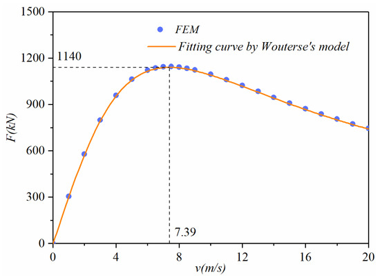
Figure 14.
Force-velocity relationship of the design example.
6. Conclusions
This paper reports the dynamic characteristics of a tubular linear eddy current damper and its performance in reducing the transient response of a linear elastic SDOF system when subjected to shock loadings. The mechanical model of the TLECD is represented by the semi-empirical model proposed by Wouterse [27], which is confirmed by electromagnetic finite element simulation in COMSOL. Response analyses have been carried out under the condition of three different types of shock excitation and various TLECD’s mechanical parameters to validate the effectiveness of the TLECD in terms of shock vibration control of structures. The influence of the physical parameters of the TLECD on its mechanical parameters is discussed, and a simplified design flow chart and a design case for mechanical parameters are given. The following conclusions are obtained:
(1) The dynamic characteristic of the TLECD can be well expressed by Wouterse’s model, with approximately linearized characteristics in the low-velocity section and a nonlinear feature in the high-velocity section.
(2) From the transient response analysis, TLECDs have been found effective in decreasing structural response and energy input. A larger maximum damping force and smaller critical relative velocity lead to smaller peak responses and a shorter time to reach peak responses.
(3) Under the condition of achieving the target maximum displacement, there is an optimal dimensionless critical relative velocity that minimizes the dimensionless maximum damping force and the time of the maximum displacement. In addition, the dynamic characteristics of the system with the ECD subjected to half-cycle sine shock and the initial peak triangular shock are similar when the dimensionless critical relative velocity γ is between 0.2 and 1.
(4) At the same maximum displacement and maximum damper force, the SDOF system with the TLECD takes more time to reach the maximum displacement and less time to reach one-third of the maximum displacement than the SDOF system with the FVD, and the former absorbs a little less energy from the external loading than the latter.
(5) The SRS of the SDOF system and the design flowchart for the TLECD can be considered as a ready reference for the shock vibration control of an SDOF system with the nonlinear TLECD and the estimation of dimensions and costs of TLECDs.
Overall, this paper focuses on the numerical analysis of TLECDs for SDOF systems. The conclusions are summarized according to the numerical calculations. In order to further confirm these conclusions, experimental tests are needed for the mechanical performance of TLECDs and their shock vibration control performance with structures. Moreover, further studies, such as applying TLECDs to MDOF systems and investigating the thermal effect of the TLECD, will be conducted in the future.
Author Contributions
Y.P.: Validation, Investigation, Data Curation, Writing—Original Draft, Writing—Review & Editing, Visualization. Z.H.: Methodology, Formal analysis, Validation, Visualization, Writing—Reviewing and Editing. H.Z.: Validation, Investigation, Data Curation, Writing—Reviewing and Editing. X.H.: Conceptualization, Methodology, Formal analysis, Validation, Writing—Reviewing and Editing. Y.X.: Validation, Data Curation, Writing—Reviewing and Editing. All authors have read and agreed to the published version of the manuscript.
Funding
This research was funded by the National Natural Science Foundation of China, grant number 51808210.
Institutional Review Board Statement
Not applicable.
Informed Consent Statement
Not applicable.
Data Availability Statement
Not available.
Conflicts of Interest
The authors declare no conflict of interest.
References
- Housner, G.W.; Bergman, L.A.; Caughey, T.K.; Chassiakos, A.G.; Yao, J.T. Structural Control: Past, Present, and Future. J. Eng. Mech. 1997, 123, 897–971. [Google Scholar]
- Dargush, G.F.; Soong, T.T. Passive Energy Dissipation Systems in Structural Engineering; Wiley: New York, NY, USA, 1997. [Google Scholar]
- Spencer, B.F.; Nagarajaiah, S. State of the Art of Structural Control. J. Struct. Eng. 2003, 129, 845–856. [Google Scholar] [CrossRef]
- Chopra, A. Dynamics of Structures—Theory and Applications to Earthquake Engineering; Chopra Prentice Hall: Englewood Cliffs, NJ, USA, 2007. [Google Scholar]
- Clough, R.W. Dynamics of Structures, 2nd ed.; CRC Press: Boca Raton, FL, USA, 2012. [Google Scholar]
- Yamaguchi, H. Damping of transient vibration by a dynamic absorber. Trans. Jpn. Soc. Mech. Eng. 1988, 54, 561–568. [Google Scholar] [CrossRef]
- Xiang, P.; Nishitani, A. Optimum design and application of non-traditional tuned mass damper toward seismic response control with experimental test verification. Earthq. Eng. Struct. Dyn. 2015, 44, 2199–2220. [Google Scholar] [CrossRef]
- Zhou, S.; Jean-Mistral, C.; Chesne, S. Closed-Form solutions to optimal parameters of dynamic vibration absorbers with negative stiffness under harmonic and transient excitation. Int. J. Mech. Sci. 2019, 157–158, 528–541. [Google Scholar] [CrossRef]
- Zhao, Z.; Hu, X.; Zhang, R.; Chen, Q. Analytical optimization of the tuned viscous mass damper under impulsive excitations. Int. J. Mech. Sci. 2022, 228, 107472. [Google Scholar] [CrossRef]
- Mojahed, A.; Moore, K.; Bergman, L.A.; Vakakis, A.F. Strong geometric softening–hardening nonlinearities in an oscillator composed of linear stiffness and damping elements. Int. J. Non-Linear Mech. 2018, 107, 94–111. [Google Scholar] [CrossRef]
- Batterbee, D.C.; Sims, N.D.; Stanway, R.; Wolejsza, Z. Magnetorheological landing gear: 1. A design methodology. Smart Mater. Struct. 2007, 16, 2429–2440. [Google Scholar] [CrossRef]
- Paknejad, A.; Zhao, G.; Chesné, S.; Deraemaeker, A.; Collette, C. Hybrid Electromagnetic Shunt Damper for Vibration Control. J. Vib. Acoust. 2020, 143, 021010. [Google Scholar] [CrossRef]
- Oveisi, A.; Hasheminejad, S. Active vibration control of an arbitrary thick smart cylindrical panel with optimally placed piezoelectric sensor/actuator pairs. Int. J. Mech. Mater. Des. 2015, 12, 1–16. [Google Scholar] [CrossRef]
- Balachandran, B.; Magrab, E.B. Vibrations, 3 ed.; Cambridge University Press: Cambridge, UK, 2018. [Google Scholar]
- Narkhede, D.I.; Sinha, R. Behavior of nonlinear fluid viscous dampers for control of shock vibrations. J. Sound Vib. 2014, 333, 80–98. [Google Scholar] [CrossRef]
- Narkhede, D.I.; Sinha, R. Influence of shock impulse characteristics on vibration control using nonlinear fluid viscous dampers. J. Vib. Control 2015, 23, 1463–1479. [Google Scholar] [CrossRef]
- Wen, Q.; Hua, X.G.; Chen, Z.Q.; Yang, Y.; Niu, H.W. Control of Human-Induced Vibrations of a Curved Cable-Stayed Bridge: Design, Implementation, and Field Validation. J. Bridge Eng. 2016, 21, 04016028. [Google Scholar] [CrossRef]
- Liu, M.; Li, S.; Wu, T.; Li, Y.; Meng, H.; Chen, Z. Eddy-Current Tuned Mass Dampers for Mitigation of Wind-Induced Response of the Noor III Solar Tower: Design, Installation, and Validation. J. Struct. Eng. 2021, 147, 05021009. [Google Scholar] [CrossRef]
- Meins, J.; Miller, L.; Mayer, W.J. The high speed Maglev transport system TRANSRAPID. IEEE Trans. Magn. 1988, 24, 808–811. [Google Scholar] [CrossRef]
- Abdelkareem, M.A.A.; Xu, L.; Ali, M.K.A.; Elagouz, A.; Mi, J.; Guo, S.; Liu, Y.; Zuo, L. Vibration energy harvesting in automotive suspension system: A detailed review. Appl. Energy 2018, 229, 672–699. [Google Scholar] [CrossRef]
- Huang, Z.W.; Hua, X.G.; Chen, Z.Q.; Niu, H.W. Modeling, Testing, and Validation of an Eddy Current Damper for Structural Vibration Control. J. Aerosp. Eng. 2018, 31, 04018063. [Google Scholar] [CrossRef]
- Shin, H.; Choi, J.; Cho, H.; Jang, S. Analytical Torque Calculations and Experimental Testing of Permanent Magnet Axial Eddy Current Brake. IEEE Trans. Magn. 2013, 49, 4152–4155. [Google Scholar] [CrossRef]
- Wang, J.; Lin, H.; Fang, S.; Huang, Y. A General Analytical Model of Permanent Magnet Eddy Current Couplings. IEEE Trans. Magn. 2014, 50, 8000109. [Google Scholar] [CrossRef]
- Spok-Myeong, J.; Sung-Ho, L.; Sang-Sub, J. Characteristic analysis of eddy-current brake system using the linear Halbach array. IEEE Trans. Magn. 2002, 38, 2994–2996. [Google Scholar] [CrossRef]
- Zhang, H.Y.; Chen, Z.Q.; Hua, X.G.; Huang, Z.W.; Niu, H.W. Design and dynamic characterization of a large-scale eddy current damper with enhanced performance for vibration control. Mech. Syst. Signal Process 2020, 145, 106879. [Google Scholar] [CrossRef]
- Li, Y.; Li, S.; Wang, J.; Chen, Z. A new type of damper combining eddy current damping with rack and gear. J. Vib. Control. 2021, 27, 1087–1097. [Google Scholar] [CrossRef]
- Wouterse, J.H. Critical Torque and Speed of Eddy Current Brake with Widely Separated Soft Iron Poles. IEE Proc. B (Electr. Power Appl.) 1991, 138, 153. [Google Scholar] [CrossRef]
- Ebrahimi, B.; Khamesee, M.B.; Golnaraghi, F. Eddy current damper feasibility in automobile suspension: Modeling, simulation and testing. Smart Materials and Structures 2008, 18, 015017. [Google Scholar] [CrossRef]
- Ebrahimi, B.; Khamesee, M.B.; Golnaraghi, F. A novel eddy current damper: Theory and experiment. Journal of Physics D: Applied Physics 2009, 42, 075001. [Google Scholar] [CrossRef]
- Jamolov, U.; Maizza, G. Integral Methodology for the Multiphysics Design of an Automotive Eddy Current Damper. Energies 2022, 15, 1147. [Google Scholar] [CrossRef]
- Li, J.; Yang, G. Equivalent subdomain method for performance prediction of permanent magnet eddy current brakes. IET Electr. Power Appl. 2021, 15, 1174–1186. [Google Scholar] [CrossRef]
- Li, J.; Yang, G.; Sun, Q. Characteristic and Thermal Analysis of Permanent Magnet Eddy Current Brake. Comput. Model. Eng. Sci. 2021, 126, 1011–1031. [Google Scholar] [CrossRef]
- Ge, J.; Xie, X.; Sun, Q.; Yang, G. Design and dynamic characteristics of a double-layer permanent-magnet buffer under intensive impact load. J. Sound Vib. 2021, 506, 116158. [Google Scholar] [CrossRef]
- Seok-Myeong, J.; Sung-Ho, L. Comparison of three types of permanent magnet linear eddy-current brakes according to magnetization pattern. IEEE Trans. Magn. 2003, 39, 3004–3006. [Google Scholar] [CrossRef]
- Atallah, K.; Howe, D. The application of Halbach cylinders to brushless AC servo motors. IEEE Trans. Magn. 1998, 34, 2060–2062. [Google Scholar] [CrossRef]
- Anferova, S.; Anferov, V.; Arnold, J.; Talnishnikh, E.; Voda, M.A.; Kupferschläger, K.; Blümler, P.; Clauser, C.; Blümich, B. Improved Halbach sensor for NMR scanning of drill cores. Magn. Reson. Imaging 2007, 25, 474–480. [Google Scholar] [CrossRef]
- Seok-Myeong, J.; Sang-Sub, J.; Sang-Do, C. The application of linear Halbach array to eddy current rail brake system. IEEE Trans. Magn. 2001, 37, 2627–2629. [Google Scholar] [CrossRef]
- Liang, L.; Feng, Z.; Chen, Z. Seismic Control of SDOF Systems with Nonlinear Eddy Current Dampers. Appl. Sci. 2019, 9, 3427. [Google Scholar] [CrossRef]
- Lin, W.-H.; Chopra, A.K. Earthquake response of elastic SDF systems with non-linear fluid viscous dampers. Earthq. Eng. Struct. Dyn. 2002, 31, 1623–1642. [Google Scholar] [CrossRef]
- Beyer, R.T. Shock and Vibration Handbook, 3rd ed.; Cyril, M.H., Ed.; The Journal of the Acoustical Society of America: New York, NY, USA, 1988; Volume 84, p. 1126. [Google Scholar] [CrossRef]
- Li, J.; Yang, G.; Fan, Y. Modeling and optimization of tubular linear permanent magnet eddy current brake with Halbach array. Int. J. Appl. Electromagn. Mech. 2021, 66, 91–113. [Google Scholar] [CrossRef]


Disclaimer/Publisher’s Note: The statements, opinions and data contained in all publications are solely those of the individual author(s) and contributor(s) and not of MDPI and/or the editor(s). MDPI and/or the editor(s) disclaim responsibility for any injury to people or property resulting from any ideas, methods, instructions or products referred to in the content. |
© 2023 by the authors. Licensee MDPI, Basel, Switzerland. This article is an open access article distributed under the terms and conditions of the Creative Commons Attribution (CC BY) license (https://creativecommons.org/licenses/by/4.0/).