Article

A Multi-Objective Optimization Method of a Mobile Robot Milling System Construction for Large Cabins

1
Beijing Spacecrafts, China Academy of Space Technology, Beijing 100094, China
2
School of Instrument Science and Opto-Electronics Engineering, Beijing Information Science & Technology University, Beijing 100192, China
*
Authors to whom correspondence should be addressed.
Appl. Sci. 2023, 13(4), 2288; https://doi.org/10.3390/app13042288
Submission received: 10 December 2022 / Revised: 6 February 2023 / Accepted: 8 February 2023 / Published: 10 February 2023

Abstract

:

Featured Application

This method can evaluate the performance of mobile robot milling system construction from three aspects; accuracy, efficiency and cost, without investing in actual hardware, and provide alternative schemes to ensure the correctness and effectiveness of the system construction, which can be extended to the construction process of modular systems in other fields.

Abstract

Constructing mobile robot milling systems with multiple mounting surfaces for large cabins still has several unsolved issues, such as huge economic and time costs, unpredictable milling accuracy and milling time. Hence, a multi-objective optimization method for constructing a mobile robot milling system of large cabins is proposed in the current paper. Firstly, mathematical models of constructing the system and the optimization objective function are established. Thereafter, a multi-objective optimization method for the mobile robot milling system construction based on NSGA-II (Fast Non-dominated Sorting Genetic Algorithm) is proposed. Finally, feasibility and validity of the proposed method are verified through comparing the optimization result with two practical mobile robot systems. Results show that the proposed method is able to estimate different combinations’ milling accuracy, cost and time consumption.

1. Introduction

The large cabin of a spacecraft is an important part of space information transmission equipment and core weapons of military defense, as well as a major guarantee for national security and the national economy. Its development level is a concentrated reflection of the manufacturing capability of high-end aerospace equipment. A large spacecraft cabin has the significant characteristics of large size, being lightweight, having a complex structure and so on. At present, existing research outcomes for the large cabin body multi-mounting surface combination milling mostly use large special machine tools or off-line split processing combined with an online repair manufacturing mode. But there are still problems such as unstable and complex process, poor flexibility, long cycle and so on. In recent years, the in-site machining operation mode of mobile robots has emerged with a strong environmental adaptability and high processing efficiency, which has become an effective way to solve the problems of efficient and high precision manufacturing of the large spacecraft cabin [1,2,3]. For example, the mobile robot processing system for large aircraft parts studied by the Fraunhofer Association [4], the mobile robot wind turbine blade grinding system proposed by KUKA and the KUKA MRP robot arm movement base oriented towards aircraft skin hole assembly [5], and the mobile processing robot equipment for aircraft fuselage drilling and riveting developed by Zhejiang University [6], etc.
In order to meet the requirements of flexibility, machining efficiency and machining accuracy of mobile robot in-site machining operating systems, research on equipment realization, machining mode construction and multi-scale measurement methods of mobile robots have been carried out extensively in recent years.
In the field of mobile robot equipment realization, the American Electroimpact (EI) company replaced the KUKA robot control system with the 840Dsl numerical control system, combined with joint secondary feedback technology to achieve accurate robot control, and launched the accurate robot system secondary feedback using a grating ruler. Their positioning accuracy is better than 0.25 mm. This achievement has been applied to drilling, riveting and milling of large thin-walled components in the aerospace field [7,8]. Based on EI’s program, the German Fraunhofer Association’s mobile milling robot provides real-time feedback compensation for T-Mac online measurement results through a Universal Compensation Interface, and the trajectory accuracy reaches 0.27 mm [9]. A NC driven mobile milling robot was developed by Beijing Spacecrafts Manufacturing Co., LTD. Its accuracy was improved by the NC system construction, grating compensation, kinematic parameter calibration, high precision estimation and stiffness compensation [10,11].
In the field of construction of mobile robot processing modes, the team of Ding Han of Huazhong University of Science and Technology proposed the “measurement-operation-processing integration” scheme of mobile robots in cooperation with Tsinghua University, Beijing Spacecrafts Manufacturing Co., LTD., and realized the variable thickness grinding of aircraft assembly gaskets [12]. For aerospace large carbon fiber composite structure milling, the Fraunhofer Association obtains the reference point coordinates through digital measurement and combines the best fitting method to realize the “position-finding—machining” manufacturing process of mobile milling robots [13].
In the field of multi-scale measurement methods for mobile robots, the team of Jia Zhenyuan from Dalian University of Technology proposed a combined measurement method with a 3D scanner, laser tracker and industrial robot as positioning devices to realize high-precision measurement, aiming at the contradiction between global measurement and local precision measurement control in 3D digitalization of key local features of large-size parts [14]. Professor Ren Mingjun and his team from Shanghai Jiao Tong University introduced a non-Lambert photometric stereoscopic vision method based on a multi-scale convolutional network for highly reflective metal products, which greatly improved the adaptability to non-Lambert surfaces while retaining the ability to recover fine three-dimensional morphology [15]. The Fraunhofer Association developed a mobile laser tracker measuring system, which combined with a mobile milling robot, and proposed a complete fabrication method for large thin-walled parts [16].
Many other relative topics have also been researched widely, such as robot kinematics analysis, dynamics modeling, stiffness optimization, path planning, machining flutter suppression, simulation, etc. [17,18,19,20,21,22].
Existing studies show that in-site machining of mobile robots has important research significance and wide application prospects, but there are still some problems such as unpredictable milling accuracy and efficiency after system construction, huge cost of construction and time, and the research is mostly focused on the accuracy, cost and time-consuming analysis of local units, without consideration from the system level. Therefore, aiming at the construction of mobile robot systems for multi-mounted surface milling of large cabins, an optimal system construction method for mobile robots was proposed, which was mainly based on multi-objective optimization methods, with combined consideration of the relationship between precision, cost and time. The proposed method was also verified by experiments.

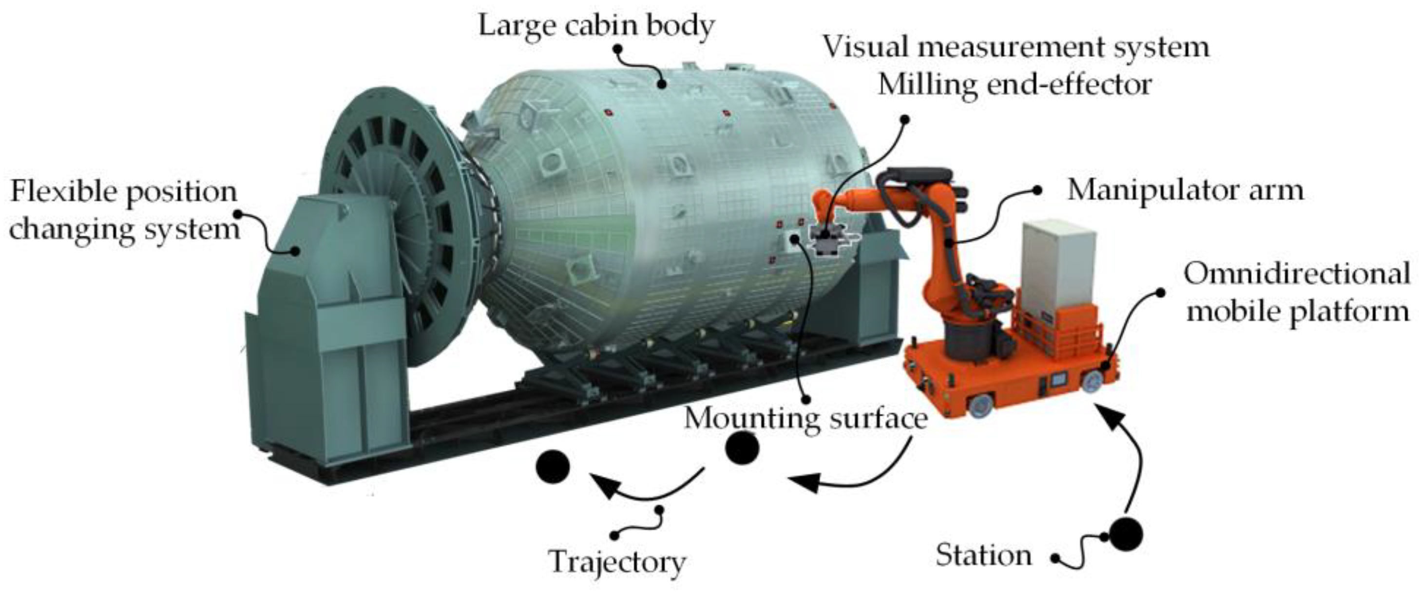
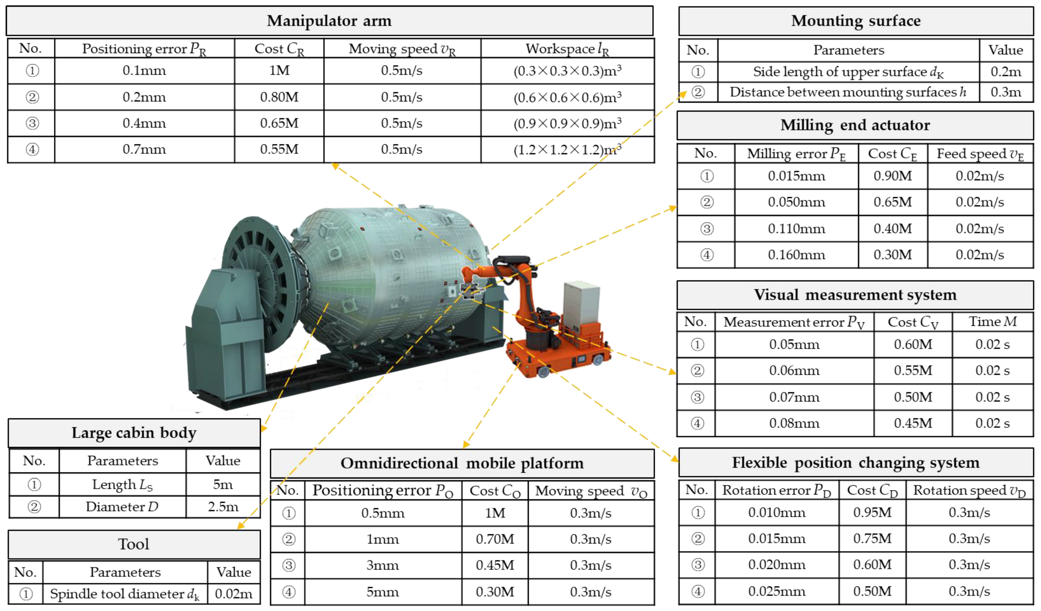
2. The Mobile Robot System

The mobile robot system for multi-mounted surface milling of large cabins is shown in Figure 1, which mainly includes an omnidirectional mobile platform, manipulator, milling end-effector, vision measurement system, large cabin, flexible position changing system, etc. The flexible position changing system is used to support and fix the large cabin body and adjust the position and pose of the cabin body. The mounting surfaces on the cabin body are milling objects. The omnidirectional mobile platform is used to bear the fixed manipulator and move the position of the manipulator. The vision measuring system is connected with the milling end-effector, which is installed at the end of the manipulator. The position and pose of the vision measuring system and milling end-effector can be adjusted by changing the position and pose of the manipulator arm.
The whole process is shown in Figure 2, which can be described as:
(1)
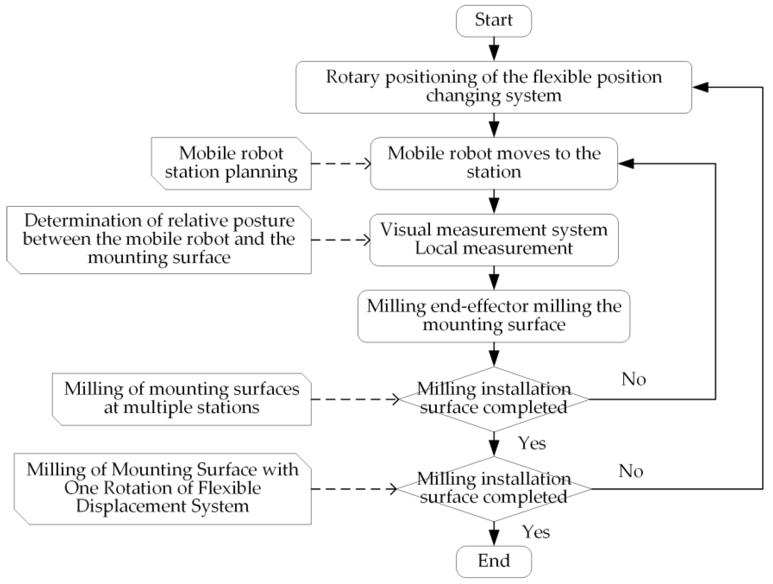
Rotary positioning of the flexible position changing system;
(2)
The mobile robot (omnidirectional mobile platform + manipulator + visual measurement system + milling end-effector) moves and positions along the trajectory according to the planned station position;
(3)
The visual measurement system corrects the relative posture between the mobile robot and the mounting surface by measuring the local target points on the large cabin body;
(4)
Milling end-effector milling the mounting surface according to the existing numerical control program;
(5)
Move the mobile robot to the lower station and repeat (2) to (5);
(6)
Rotary positioning of the flexible position changing system, repeat (2) to (6), until the installation surface has completed all milling processes.

3. Multi-Objective Optimization of System Construction

3.1. Characteristics of System Construction and Its Mathematical Description

In order to optimize the construction of the mobile robot system, the objective function optimized by the construction system should be determined first, which means, the evaluation criteria of the optimal system construction should be determined, and the mathematical model of the optimal system construction method should be established.
The omnidirectional mobile platform, mechanical arm, flexible position changing system have positioning errors, transmission errors and clearance errors. The visual measurement system has measurement errors and random errors caused by environmental factors. In the actual system construction process, the above errors will lead to different final accuracies guaranteed by the constructed system. Generally, the higher the cost of equipment or system is, the higher the accuracy is, this is because of the high cost of precision improvement methods and hardware. Different milling processes (different station planning, different precision allocation, etc.) will lead to a different system running time and efficiency. Therefore, the three factors of system accuracy, cost and time consumption will be coordinated and selected according to actual requirements. Based on the above analysis and actual engineering application requirements, the characteristics required for optimal system construction can be defined as follows:
(1)
The error accumulation of the constructed mobile robot system is minimal;
(2)
The total cost of the mobile robot system is the lowest;
(3)
The milling time of all the large cabin faces of the constructed mobile robot system is the shortest.
The above description form cannot be used for quantitative analysis of the construction process of the optimal system of mobile robots by mathematical operations, so it is necessary to use mathematical language to express and optimize the above description. The mathematical model of the optimal system construction can be defined as:
m i n   f 1 = P R + P V + P E + P D m i n   f 2 = C O + C R + C V + C E + C D m i n   f 3 = T O + T R + T V + T E + T D
In Equation (1), The precision P here mainly refers to the precision of the product after the mobile robot milling system is moved to the specified position and processed. The precision is affected by the positioning error of the manipulator, the machining error of the milling end actuator, the measurement error of the visual measurement system, and the positioning error of the flexible displacement system. It is the superposition of the above link errors, P > 0. The cost C here mainly refers to the hardware cost of constructing the mobile robot milling system, which is the superposition of the hardware costs of the omni-directional mobile platform, the manipulator, the milling end actuator, the visual measurement system, and the flexible displacement system, C > 0. The efficiency T here mainly refers to the time required for the mobile robot milling system to process from moving to the specified position until the processing is completed. This time includes the moving time of the omni-directional mobile platform, the movement time of the manipulator, the processing time of the milling end actuator, the measurement time of the visual measurement system, and the movement time of the flexible displacement system. The superposition of the above link time is the efficiency, T > 0. Since the positioning error of the omnidirectional mobile platform was corrected through the measurement of local target points by the visual measurement system, the positioning error PO of the omnidirectional mobile platform was subtracted from the final milling error f1. The total cost of the mobile robot system f2 is the sum of the market price of all components and f3 is the sum of the time spent on all milling processes. The meanings of each parameter are shown in Table 1.
It is assumed that the installation surface of the large cabin body to be processed is square, and the side length is lK, and the installation surfaces are evenly distributed on the outer surface of the cabin body with the spacing h. LS is the length of the large cabin body, D is the diameter of the large cabin body (as shown Figure 3), lR is the length of the working space side of the manipulator (regarded as a cube, and lR/lK > 1).
In general, positioning errors of the manipulator are related to the working space, and the larger the working space is, the larger the positioning error will be. Therefore, the manipulator’s working space is taken as the constraint, and the large cabin body is divided along the axial and radial directions. The segmentation method is as follows:
R o w = L S l R , C o l   = D π l R
The following parameter calculation methods can be obtained:
T O = C o l × R o w × l R v O T R = C o l × R o w × ( ( n + 2 ) × n × h v R ) , T V = C o l × R o w × M T E = C o l × R o w × ( n + 1 ) 2 × l K d K × l K v E   T D = C o l × l R v D
In Equation (3), vO represents the movement speed of the omnidirectional mobile platform; vR represents the speed at which the manipulator moves; M is a constant, representing the time of the target point of visual measurement; dK stands for milling spindle tool diameter; vE represents the feed speed of the main shaft; D is the diameter of the large cabin; vD represents the moving speed of the flexible positioning system, and n is calculated by the following pseudo-code, n = 0, 1, 2, …:
n = 0 ; D o {                 i f ( l R n × h + l K < 1 )   {                         b r e a k ;             }               n = n + 1 ;   } w h i l e ( true ) ;
Based on the movement speed of the omnidirectional mobile platform, TO is calculated. In the manipulator working space, the surface milling of multiple mounting surfaces is carried out. As the workspace becomes larger or smaller, the number of mounting surfaces to be milled will increase or decrease. TR is calculated by combining with the manipulator moving speed. In the manipulator working space, each mounting surface is divided by the tool diameter, combined with the feed speed, the milling time of a single mounting surface is calculated, and then the milling time TE of multiple surfaces in the working space can be calculated. With the manipulator workspace as a constraint, the large cabin body is segmented along the circumference, and TD is calculated based on the speed of the flexible position changing system.
The mathematical model of Equation (1) includes three objective functions, which are f1, f2 and f3, respectively. The process of constructing the optimal mobile robot system is a typical multi-objective optimization problem. However, the relationship between these three objective functions is contradictory, which also compounds the universality problem of multi-objective optimization. Generally speaking, it is difficult to solve the global optimal solution which minimizes the three objective functions at the same time. We can find the non-inferior solution of the multi-objective optimization problem as an alternative to the optimal solution. In this paper, a multi-objective optimization problem for a mobile robot system oriented to multi-installation surface milling of large cabin bodies is presented by using a Non-dominated Sorting Genetic Algorithm II (NSGA-II) with an elite strategy.

3.2. A Multi-Objective Optimization Method for System Construction Based on a Genetic Algorithm

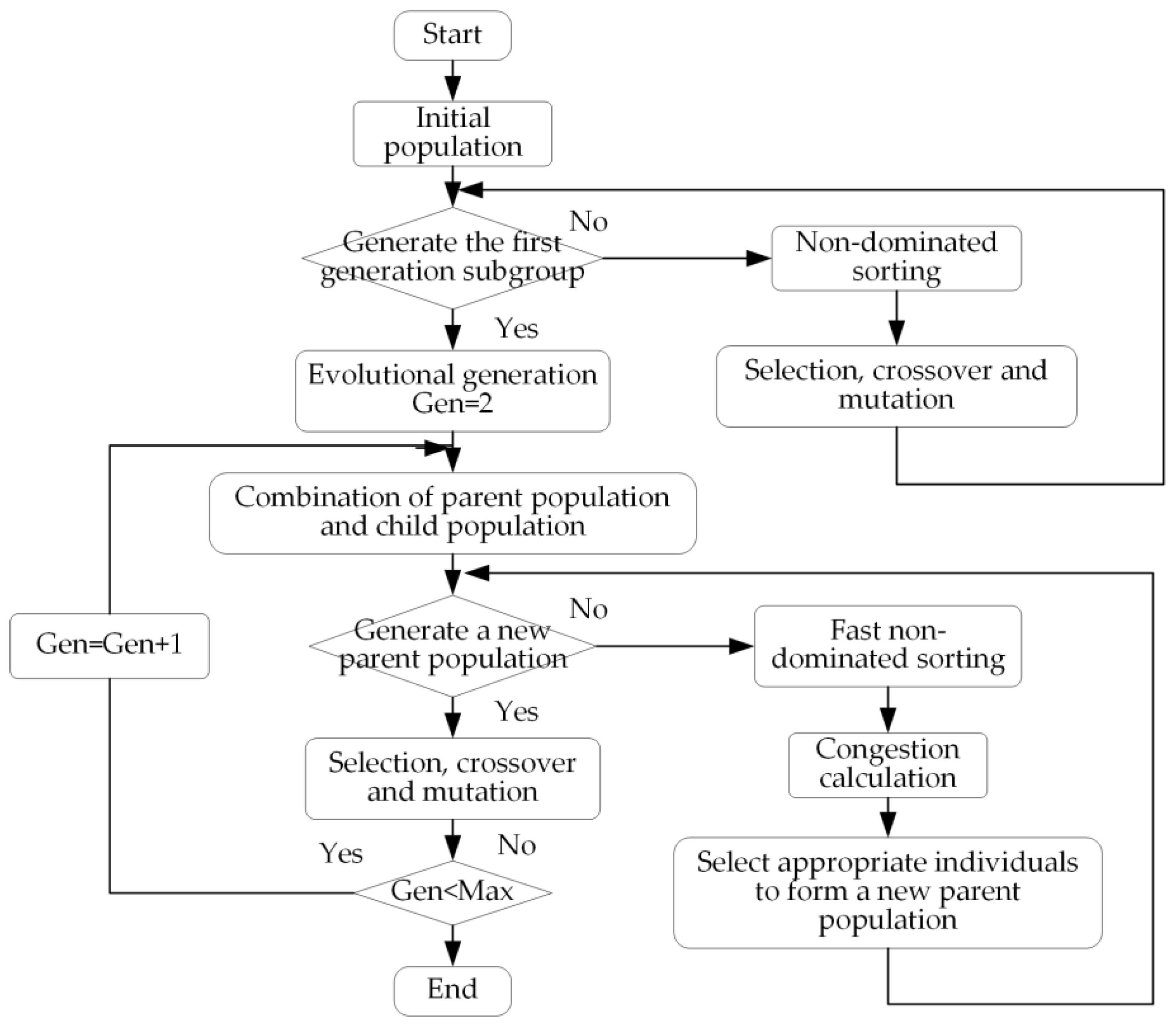
3.2.1. NSGA-II Algorithm

NSGA-II is a genetic algorithm used to solve the multi-objective optimization problem. This method improves the sorting method of the basic genetic algorithm and puts forward the fast non-dominated sorting method, which enables the genetic algorithm to solve the multi-objective optimization problem and reduces the complexity of the non-inferior sorting genetic algorithm. It has the advantages of fast running speed and good convergence of the solution set. It is an algorithm widely used in the field of multi-objective optimization. The process of the NSGA-II algorithm is shown in Figure 4.
The basic implementation steps of the NSGA-II algorithm are as follows:
(1)
The initial population is randomly generated, and the size was N. The non-dominated queuing is performed on the initial population, and the selection, crossover and mutation operations are carried out on the initial population by the genetic algorithm to obtain the first-generation progeny population.
(2)
The combination of parent population and child population in the second generation, and the rapid non-dominant sequencing is carried out, and the crowding degree of individuals in each non-dominant layer is calculated, and the appropriate individuals are selected to form a new parent population according to the non-dominant relationship between individuals. Starting from the second generation, the following generations are treated in the same way.
(3)
The genetic algorithm is used to select, cross and mutate the parent population to generate a new offspring population.
(4)
Repeat steps (2) and (3) until the constraints of the algorithm are met.

3.2.2. Multi-Objective Optimization of Mobile Robot System Construction

Most of the existing mobile robot system construction relies on human experience, and make sufficient allowance in the accuracy, cost and efficiency of each component. The constructed scheme is not the best. On this basis, the current paper proposes a multi-objective optimization method for mobile robot system construction based on NSGA-II, which is mainly composed of a genetic algorithm population by analyzing the influence rules among the precision, cost and time of the components of omnidirectional mobile platform, manipulator, milling end-effector, vision measurement system and flexible position changing system, combined with the actual system construction data. It can be understood that there are five types of components, and each type of component has multiple specific components according to the relationship between precision, cost and time. One specific component is selected from the five types of components to put in the system, so that the system has the smallest accumulation of errors, the lowest total cost and the shortest time spent on all the installation surface milling. The multi-objective optimization flow chart of the mobile robot system construction based on NSGA-II is shown in Figure 5.
The concrete steps of constructing the multi-objective optimization method for the mobile robot system based on NSGA-II are as follows:
(1)
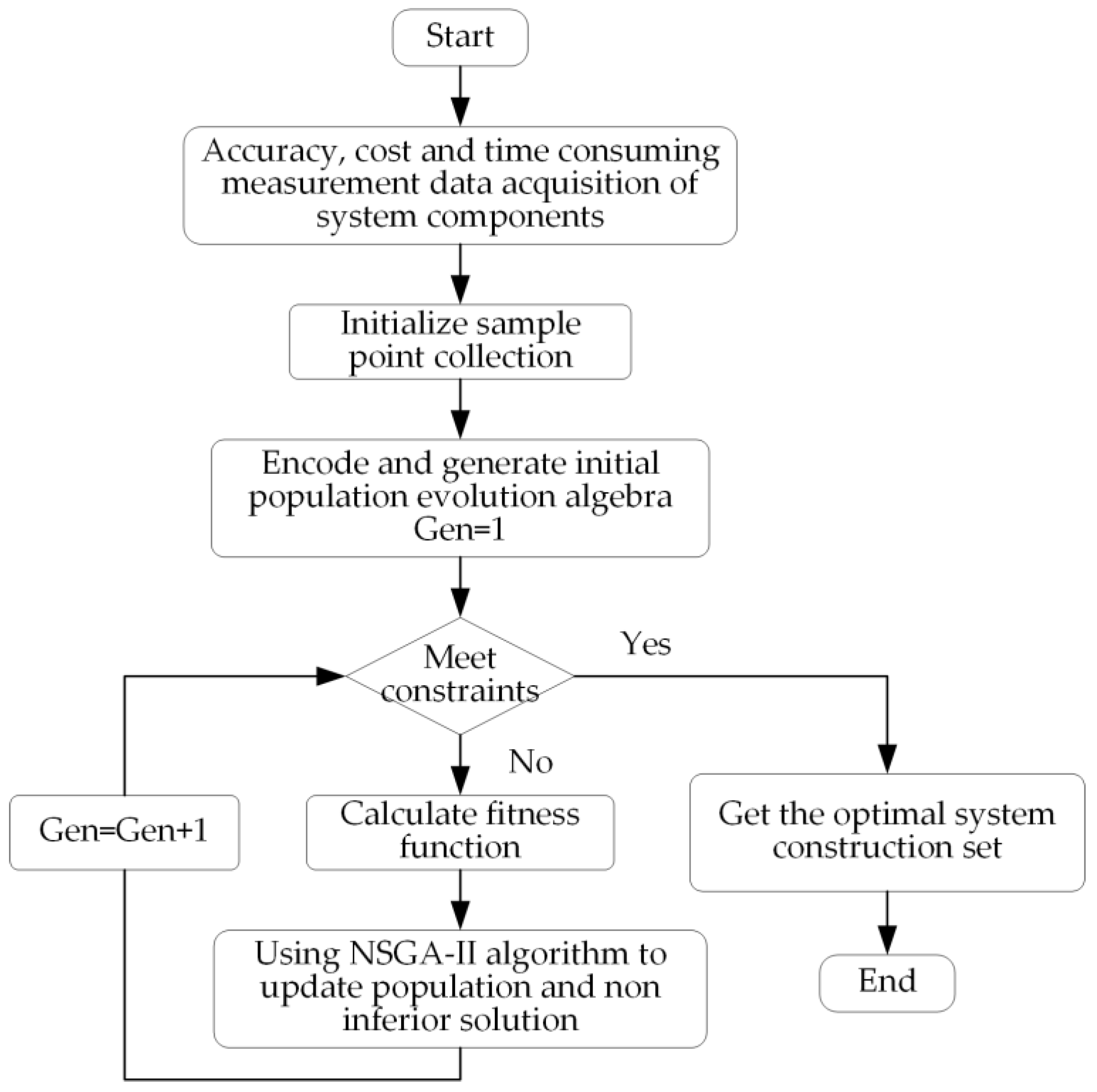
Measured data acquisition: the positioning accuracy of the omnidirectional mobile platform is related to the measurement method, and the positioning accuracy of laser navigation is generally 3 mm. Based on two-dimensional code visual measurement positioning, positioning accuracy is generally 1 mm. The navigation and positioning accuracy of a high precision spatial locator (iGPS) is generally 0.5 mm. Composite measurements can ensure higher positioning accuracy, but the cost is also higher. At the same time, the higher the precision, the longer the time to adjust and control. There are many ways to improve the positioning accuracy of the manipulator, such as correcting D-H parameters to improve the error compensation. The grating two-stage closed-loop is used to improve the joint angle accuracy and then the robot positioning accuracy. The higher the accuracy, the higher the cost, and the smaller the working space. The accuracy of the vision measurement system, milling end-effector and flexible position changing system are also positively correlated with the cost.
(2)
Initialize component set: According to step (1), components are classified and selected according to accuracy, cost and time, and multiple groups of actual data constitute the initial population of the genetic algorithm.
(3)
Coding and generating population: the number of system components is represented by m, and the number of specific components in the component is represented by n. Rows and columns of the matrix are used for coding, that is, columns represent m components and rows represent n specific components. Then the coding of the constructed system can be obtained and corresponds to the matrix of precision, cost and time.
(4)
Fitness calculation: there are three goals. The first goal is the sum of the error accumulation of each component in the milling process, the second goal is the sum of the cost of each component, and the third goal is the sum of the working time of each component. Its fitness function is shown in Equation (1).
(5)
Update population and non-inferior solution set: For the populations processed by the above steps, the non-inferior solution set constructed by the optimal system can be updated through the NSGA-II genetic algorithm operations such as fast non-dominant sorting, crowding calculation, selection, crossover and mutation, and the updated new population can be used for the next generation calculation.
(6)
Iterative optimization: Repeat steps (4)~(5) until the constraint condition (the set number of iterations) is satisfied, and the final non-inferior solution set of the optimal system can be obtained.

4. Verification and Analysis

4.1. Application of the Multi-Objective Optimization Method in Optimal System Construction

Based on the above analysis, the measured data was first collected and summarized, and the component set was initialized as shown in Figure 6. The precision, efficiency and cost of omni-directional mobile platform, manipulator, milling end actuator, visual measurement system and flexible displacement system are related. The manuscript directly gives the results of the relationship among precision, efficiency and cost through the existing data, without detailed analysis.
According to the optimization method proposed in the previous section and the data in Figure 5, 300 iterations of the algorithm were performed on 100 populations after the convergence of the algorithm. The non-inferior solution set of 89 optimal sampling points was finally obtained, as shown in Figure 7.
In Figure 6a, the x-coordinate is the cumulative error of the constructed mobile robot system and represents the fitness value of the objective function f1. The y-coordinate is the sum of the cost of the constructed mobile robot system and represents the fitness value of the objective function f2. In Figure 6b, the x-coordinate represents the fitness value of the cumulative error objective function f1. The y-coordinate is the time spent in milling all the multi-mounting surfaces of the large cabin of the constructed mobile robot system and represents the fitness value of the objective function f3. In Figure 6c, the x-coordinate represents the fitness value of the objective function f2 of the sum of costs; The y-coordinate is the fitness value of the milling time objective function f3. In Figure 6d, the coordinates represent the fitness value of cumulative error objective function f1, the fitness value of cost sum objective function f2, and the fitness value of milling time objective function f3.
By analyzing the multi-objective optimization results of the optimal system construction, the following information can be obtained:
(1)
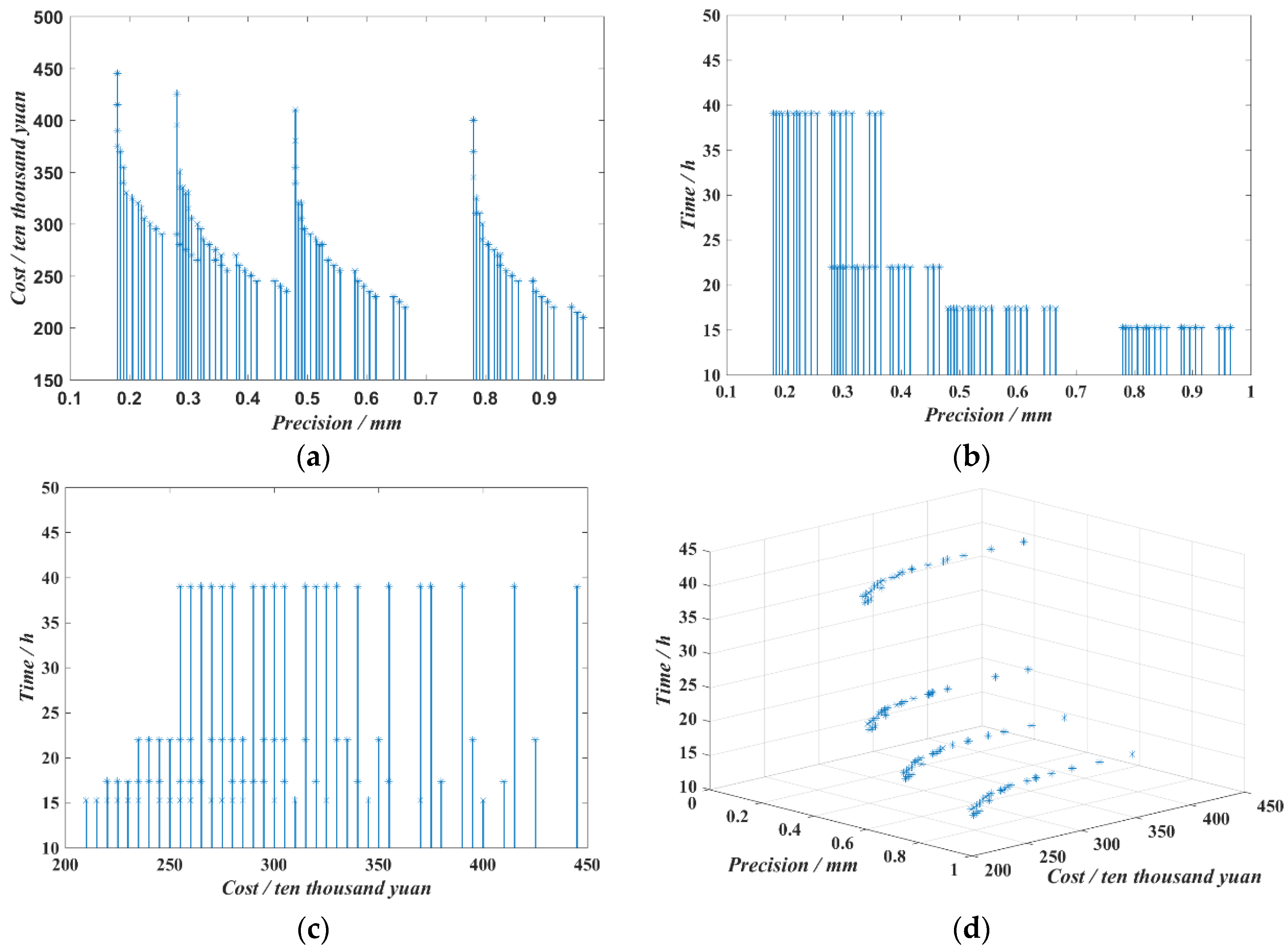
There is a significant negative correlation between the cumulative error and the sum of costs in Figure 6a, a significant negative correlation between the cumulative error and the milling time in Figure 6b, and a positive correlation between the sum of costs and the milling time in Figure 6c, indicating that the three objective functions are contradictory to each other;
(2)
Considering the actual design requirements, existing equipment status and subsequent support funds and other factors, the non-inferior solution set in Figure 6d can select the appropriate mobile robot system and determine the component requirements according to the corresponding code, which can ensure that the accuracy, cost and time of the system meet the construction requirements.

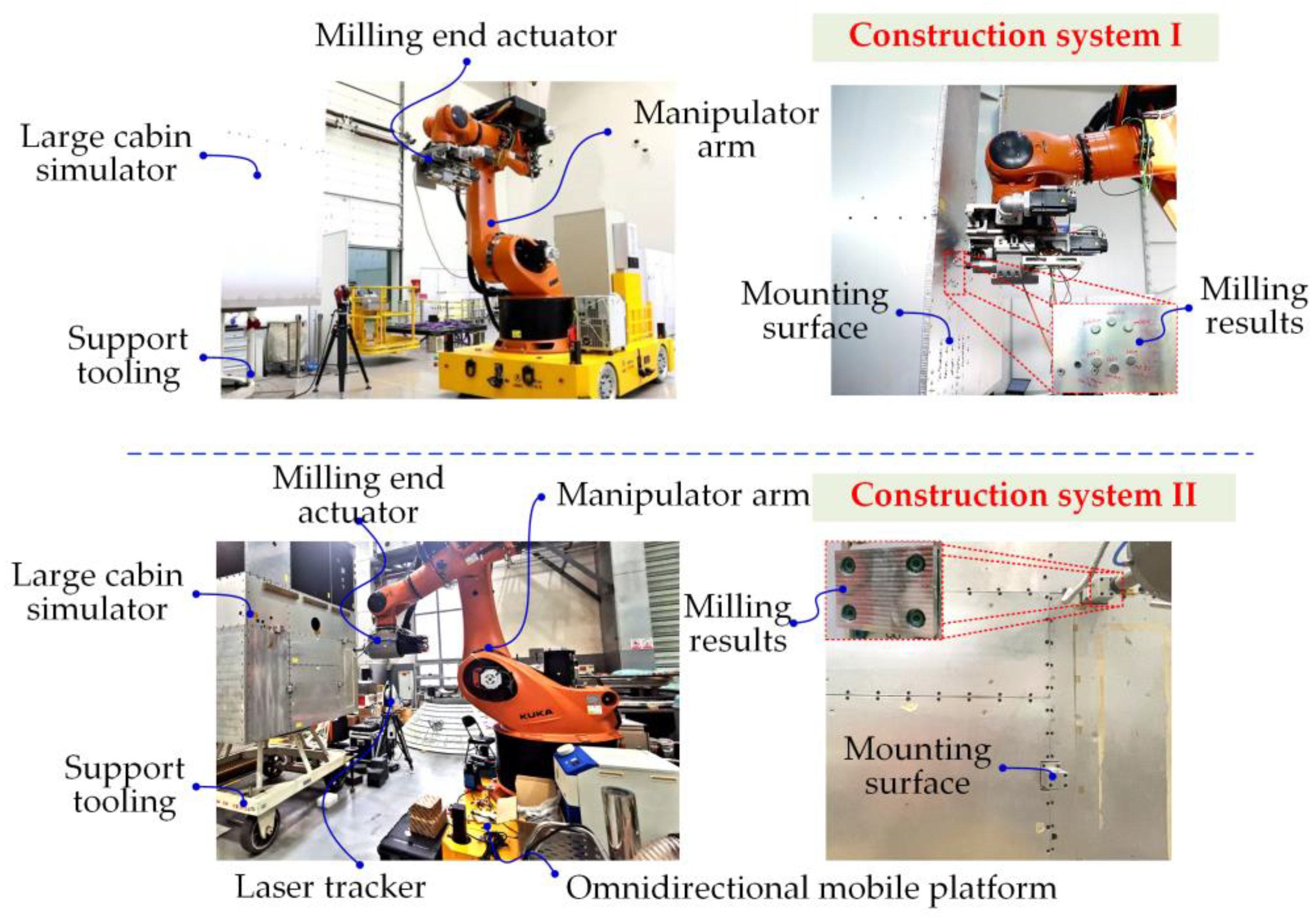
4.2. Validation of Optimization Methods for Applications

According to the non-inferior solution set constructed by the optimal system in the above section, two sets of mobile robot systems were constructed based on the existing equipment and accuracy to verify the correctness and effectiveness of the optimization method. According to Figure 5 and Figure 6, System 1 and System 2 were constructed, and the corresponding data were obtained. The specific selection is shown in Table 2.
As can be seen from the data in Table 2, the constructed System 1 has two working schemes by changing the working space of the manipulator. Scheme 1: the omnidirectional mobile platform carries the manipulator to one position for installation face milling, and then the omnidirectional mobile platform carries the manipulator to another position for installation face milling. Scheme 2: The omnidirectional mobile platform carries the robot to one position and completes the milling of two mounting surfaces in turn. Compared with the two schemes, it can be seen that the larger working space of the manipulator leads to the reduction in accuracy. Although it can process two more mounting surfaces in one position, and the cost is reduced and the efficiency is improved, the final milling error is increased. Similarly, the same conclusion exists for construction System 2. By comparing the constructed System 1 and System 2, it can be concluded that by selecting an end-effector with different precision and manipulator with different workspace, the combination can select appropriate programs of milling error, total cost and milling time.
Figure 7 shows Scheme 1 of the actual construction System 1 and Scheme 2 of the constructed System 2. According to the actual system composition, the flexible positioning tool is changed into a fixed tool, the vision measurement system is changed into a laser tracker, and the cost is still calculated as before. The length of the large cabin body is 1.5 m, and only two mounting surfaces are processed, with a spacing of 0.3 m between the mounting surfaces. The machining accuracy of the mounting surface of the large cabin is required to be 0.04 mm. The milling end-effector in the constructed System 1 has two degrees of freedom of linear motion, and the milling end-effector in the constructed System 2 is an integrated spindle with higher accuracy. The accuracy and cost of the two are shown in Figure 8.
By using scheme 1 of System 1, and Scheme 2 of System 2 constructed in Table 2 to milling multiple mounting surfaces, the error transmission route is shortened due to the difference in actual system combination, and the accuracy of each link is partially coupled, so there is deviation between the actual results and the calculated results, as shown in Table 3 below. The trend of the two constructed systems is the same as that of the optimized system. The milling error, total costs are similar, and the proportion of milling time between Scheme 1 and Scheme 2 is consistent between the predicted results and the actual results, so the correctness and effectiveness of the method are verified. The final milling error f1 is expressed as the maximum error in the Z-axis direction of the milled mounting surface in the local reference coordinate system. The laser tracker is used to measure the Z-axis direction of the milling plane, and the absolute error with the theoretical value is taken to obtain the final milling error.

5. Conclusions

Aiming at the problems such as unpredictable precision, construction cost, manufacturing cost and time cost, a mathematical model of mobile robot system construction for multi-mounting surface milling of large spacecraft cabins was proposed, and a multi-objective optimization method for mobile robot system construction based on a genetic algorithm was proposed, which gave the optimal solution of system construction. The effectiveness and feasibility of the method were verified by experiments.
The method in the current paper can build an effective milling system of mobile robots according to the needs of machining objects, and estimate its construction cost, machining accuracy and machining efficiency, so as to realize the prediction of milling accuracy in advance. In addition, under the existing equipment and processing conditions, this method can be used to reasonably select mobile robots, measuring equipment, omnidirectional mobile platform, and other units, which can ensure the processing accuracy, maximize the productivity, and provide guidance for the construction of the on-site engineering system.

Author Contributions

Conceptualization, K.W. and J.Z.; methodology, K.W.; software, K.W.; validation, K.W., T.C. and X.Z.; formal analysis, Z.Z.; investigation, K.W.; resources, W.Z.; data curation, Z.Z., T.C., X.Z. and K.W.; writing—original draft preparation, K.W.; writing—review and editing, K.W. and Z.Z.; visualization, K.W.; supervision, J.Z.; project administration, X.G. All authors have read and agreed to the published version of the manuscript.

Funding

This research was funded by National Natural Science Foundation of China, grant number 62003346, 52075533, 52275517 and by National Defense Basic Scientific Research program of China, grant number 2021203B035.

Institutional Review Board Statement

No applicable.

Informed Consent Statement

No applicable.

Data Availability Statement

Data is contained within the article.

Conflicts of Interest

The authors declare no conflict of interest.

References

  1. Xie, F.G.; Mei, B.; Liu, X.J.; Zhang, J.B.; Yue, Y. Novel Mode and Equipment for Machining Large Complex Components. J. Me-Chanical Eng. 2020, 56, 70–78. [Google Scholar]
  2. Tao, B.; Zhao, X.; Li, R.; Ding, H. Research on robotic measurement-operation-machining technology and its application. China Mech. Eng. 2020, 31, 49–56. [Google Scholar]
  3. Verl, A.; Valente, A.; Melkote, S.; Brecher, C.; Ozturk, E.; Tunc, L.T. Robots in machining. CIRP Annals. 2019, 68, 799–822. [Google Scholar] [CrossRef]
  4. Möller, C.; Schmidt, H.C.; Koch, P.; Böhlmann, C.; Kothe, S.-M.; Wollnack, J.; Hintze, W. Machining of large scaled CFRP-Parts with mobile CNC-based robotic system in aerospace industry. Procedia Manuf. 2017, 14, 17–29. [Google Scholar] [CrossRef]
  5. Waurzyniak, P. Expanding the Horizons of Aerospace Automation. Manuf. Eng. 2016, 156, 59–67. [Google Scholar]
  6. Guo, Y.; Dong, H.; Wang, G.; Ke, Y. Vibration analysis and suppression in robotic boring process. Int. J. Mach. Tools Manuf. 2016, 101, 102–110. [Google Scholar] [CrossRef]
  7. Jackson, T. High-Accuracy Articulated Mobile Robots; SAE Technical Paper; SAE International: Warrendale, PA, USA, 2017; pp. 1–6. [Google Scholar] [CrossRef]
  8. Logemann, T. Mobile Robot Assembly Cell (RACe) for Drilling and Fastening; SAE Technical Paper; SAE International: Warrendale, PA, USA, 2016; pp. 1–6. [Google Scholar] [CrossRef]
  9. Susemihl, H.; Moeller, C.; Kothe, S.; Schmidt, H.C.; Shah, N.; Brillinger, C.; Wollnack, J.; Hintze, W. High Accuracy Mobile Robotic System for Machining of Large Aircraft Components. SAE Int. J. Aerosp. 2016, 9, 231–238. [Google Scholar] [CrossRef]
  10. Wen, K.; Zhang, J.B.; Yue, Y. Method for improving accuracy of NC-driven mobile milling robot. J. Mech. Eng. 2021, 57, 72–80. [Google Scholar]
  11. Chen, Q.-T.; Yin, S.; Zhang, J.-B.; Yue, Y.; Zhou, Y.-H.; Wen, K.; Yang, J.-Z.; Bai, X.-P. Pose Optimization of Industrial Robots Based on Stiffness for Milling Tasks. Robot 2021, 43, 90–100. [Google Scholar]
  12. Tao, B.; Zhao, X.; Ding, H. Mobile-robotic machining for large complex components: A review study. Sci. China Technol. Sci. 2019, 62, 1388–1400. [Google Scholar] [CrossRef]
  13. Susemihl, H.; Brillinger, C.; Stürmer, S.P.; Hansen, S.; Boehlmann, C.; Kothe, S.; Wollnack, J.; Hintze, W. Referencing Strategies for High Accuracy Machining of Large Aircraft Components with Mobile Robotic Systems; SAE Technical Paper; SAE: Warrendale, PA, USA, 2017. [Google Scholar]
  14. Zhou, Z.; Liu, W.; Wu, Q.; Wang, Y.; Yu, B.; Yue, Y.; Zhang, J. A Combined Measurement Method for Large-Size Aerospace Components. Sensors 2020, 20, 4843. [Google Scholar] [CrossRef] [PubMed]
  15. Ren, M.; Fu, L.; Xiao, G.; Chen, M.; Wang, X. Non-Lambertian photometric stereo vision algorithm based on a multi-scale convolution deep learning architecture. Sci. Sin. Technol. 2020, 50, 323–334. [Google Scholar] [CrossRef]
  16. Brillinger, C.; Susemihl, H.; Ehmke, F.; Staude, T.; Deutmarg, K.; Klemstein, M.; Boehlmann, C.; Hintze, W.; Wollnack, J. Mobile Laser Trackers for Aircraft Manufacturing: Increasing Accuracy and Productivity of Robotic Applications for Large Parts; SAE Technical Paper; SAE International: Warrendale, PA, USA, 2019; pp. 1–7. [Google Scholar] [CrossRef]
  17. Tao, B.; Zhao, X.; Ding, H. Study on robotic mobile machining techniques for large complex components. Sci. Sin. Technol. 2018, 48, 1302–1312. [Google Scholar] [CrossRef]
  18. Chen, Y.-D.; Chang, S.-L.; Feng, Q.-G. Industrial robot system based on CPS approach. J. Beijing Univ. Aeronaut. Astronsutics 2018, 44, 931–938. [Google Scholar]
  19. Li, G.; Zhu, W.; Dong, H.; Ke, Y. Stiffness-oriented performance indices defined on two-dimensional manifold for 6-DOF in-dustrial robot. Robot. Comput. Integr. Manuf. 2021, 68, 102076. [Google Scholar] [CrossRef]
  20. Wu, M.; Dai, S.-L.; Yang, C. Mixed Reality Enhanced User Interactive Path Planning for Omnidirectional Mobile Robot. Appl. Sci. 2020, 10, 1135. [Google Scholar] [CrossRef]
  21. Wu, H.; Wang, Y.; Wei, X.; Zhu, D. Spatial Path Planning for Robotic Milling of Automotive Casting Components Based on Optimal Machining Posture. Metals 2022, 12, 1271. [Google Scholar] [CrossRef]
  22. Yang, B.; Guo, K.; Sun, J. Chatter Detection in Robotic Milling Using Entropy Features. Appl. Sci. 2022, 12, 8276. [Google Scholar] [CrossRef]
Figure 1. Mobile robot system for multi-mounting surface milling of large cabins.
Applsci 13 02288 g001
Figure 2. Process flow of mobile milling robot system.
Applsci 13 02288 g002
Figure 3. Parameter meanings.
Applsci 13 02288 g003
Figure 4. NSGA-II algorithm flow chart.
Applsci 13 02288 g004
Figure 5. Construction of the multi-objective optimization process for the mobile robot system based on NSGA-II.
Applsci 13 02288 g005
Figure 6. Initialized data.
Applsci 13 02288 g006
Figure 7. The non-inferior solution set for optimal system construction. (a) Construction of error and cost optimal system; (b) Construction of optimal error and time-consuming system; (c) Construction of cost and time-consuming system; (d) Optimal system construction for error, cost and time.
Applsci 13 02288 g007
Figure 8. On-site construction of mobile robot systems.
Applsci 13 02288 g008
Table 1. The meaning of each parameter.
ParameterMeaning
PRthe positioning error of the manipulator
PVthe measurement error of the visual measurement system
PEmachining error of end effector in milling
PDthe rotation error of the flexible position changing system
COthe market price (cost) of an omnidirectional mobile platform
CRthe market price of the mechanical arm
CVthe market price of a visual measurement system
CEthe market price of milling end-effector
CDthe market price of the flexible position changing system
TOthe time when the omnidirectional mobile platform participates in the milling process
TRthe time for the manipulator to participate in the milling process
TVthe time when the visual measurement system participates in the milling process
TEthe time that the end effector participates in the milling process
TDthe time that the flexible position changing system participates in the milling process
Table 2. System construction.
SystemSystem 1System 2
Scheme 1Scheme 2Scheme 1Scheme 2
Omnidirectional mobile platform
Arm of machinery
Visual measurement system
Milling end-effector
Flexible position changing system
Final milling error f1 (mm)0.3450.4450.2350.335
Total cost f2 (ten thousand Yuan)265245300280
Milling time f3 (hour)39.4529.89139.4529.891
Table 3. The actual processing result of the mobile robot.
ParametersFinal Milling Error f1 (mm)Total Cost f2
(Ten Thousand Yuan)
Milling Time f3 (Hour)
Scheme 1 of System 10.3842650.615
Scheme 2 of System 20.3562800.152
Disclaimer/Publisher’s Note: The statements, opinions and data contained in all publications are solely those of the individual author(s) and contributor(s) and not of MDPI and/or the editor(s). MDPI and/or the editor(s) disclaim responsibility for any injury to people or property resulting from any ideas, methods, instructions or products referred to in the content.

