Abstract
The historical management of underground utilities such as communication lines, water and sewage pipes, and power lines is essential for their effective use. However, due to the nature of the buried facilities, detecting and tracking them are challenging, although various solutions are difficult to apply in the field, especially optical cables, which are mainly used for communication, making it more difficult to apply existing solutions. There has been limited research on the practicalities of solutions, especially on multilayer structures such as road pavements. Based on a literature review, we selected ultra-high-frequency radio frequency identification (UHF RFID), which is least affected by performance degradation or interference due to batteries. We experimented to identify the signal attenuation based on the medium by controlling the materials and moisture used in the road pavement as variables. The signal reached a depth of 68 cm and this was possible under conditions of asphalt and subgrade soil. In a comparative experiment for each variable, we recognized tags of sand and coarse aggregate up to a depth of 70 cm. When the moisture was considered, the signal attenuation difference was 1.8 dBm for each level. Based on the experimental results of this study, it was confirmed that UHF RFID can be used as a marker sensor to be attached to utilities installed under the road pavement. Depending on the structure and material of the pavement, the signal is sufficiently transmitted up to 40–50 cm, which is the target installation depth of the communication line.
1. Introduction
Utilities for various purposes, such as communication lines, water and sewage pipes, power pipes, gas pipes, and heat transport pipes for heating, are usually installed under the pavement. However, underground utilities are difficult to manage because of their complexity and invisibility. During the five years from 2014 to 2019, 13 gas leakage accidents occurred in Seoul, and 10 of them were cases in which gas pipes were damaged during other excavation work [1]. The destruction of underground utilities resulted in high social costs being paid nationwide and increased public anxiety [2].
According to several studies, including the Federal Highway Administration (FHWA) report, the biggest threat to project completion delays and budget shortages in highway planning/design/construction is incorrect utility location information [3,4]. In other words, an underground utility management system can minimize the risk to the project caused by excavation work. Damage caused by natural disasters can be reduced as well by identifying and recording the location information of underground utilities as necessary.
Especially in Korea, due to the competition among private operators, overhead communication lines on utility poles have become crowded. For urban aesthetics and safety, a project to move the communication cables underground is in progress. The communication lines are to be installed at a depth of 40–50 cm by the trenching excavation method. Since this is relatively shallow, it is expected to come into conflict with other utilities, and it is necessary to manage their location and history.
Various solutions have been developed and proposed. According to the literature, UHF RFID is determined as a proper alternative. However, research on applications of UHF RFID under the pavement are limited. For field application, verification studies should be conducted.
In this study, we aim to determine the feasibility of using the UHF RFID tag for utility management installed under a pavement. The limitations are presented through a laboratory experiment, such as the depth of the installation and the materials of pavement.
We determine the signal reach by simulating a multilayer medium representing the road substructure and installing tags at different depths. This study makes a novel contribution to the literature by proposing the applicability of the UHF RFID tag in a multilayer structure composed of heterogeneous materials, which was not considered in previous studies.
2. Background
For the effective utilization of underground utility management technology, a technology that can grasp location information inexpensively and conveniently is essential. Existing technologies include electromagnetic locators, ground penetrating radar (GPR), and RFID [5]. All three technologies use electromagnetic waves to locate underground utilities. However, they differ in their utilization methods.
The electromagnetic locator method is a search method for electromagnetic fields generated or intentionally induced in underground utilities, and it can utilize various frequencies depending on the purpose [6]. As it detects metallic pipes, tracking lines should be attached to underground utilities with low conductivity. It is difficult to use if the connection is poor or the tracking line is damaged. If the distance between the underground utilities is significantly short, interference between electromagnetic fields occurs, making it difficult to detect the exact location [7]. The underground detection method using GPR was developed in Germany around 1911 and has been actively developed and utilized since the 1970s [8]. It uses the transmission/reception time difference of electromagnetic waves reflected from the interface of different media to locate underground utilities [9]. GPR is utilized in various types of methods such as time domain, FMCW (Frequency Modulated Continuous Waveform), and SFCW (Stepped Frequency Modulated Waveform) [10]. There are previous studies on recognizing underground facilities by applying GPR [11].
The electromagnetic locator has disadvantages when the tracking cable is damaged. In addition, when the underground area is crowded or cables are installed very close to each other, interference occurs between electromagnetic fields, making it difficult to measure the location. In the case of the ground penetrating radar method, the accuracy is low, and there is deviation between the analyst’s experience and personal interpretation. It is not suitable for use in multistory structures, i.e., road structures with multiple interfaces.
Since both methods can only find the shape of buried objects in the ground, but cannot provide information (data), it is difficult to help systematic history management. To overcome these disadvantages, it is possible to use the location search equipment to which RFID technology is applied. This is advantageous for history management by increasing the accuracy of location exploration and reliably maintaining utility information. The Virginia Department of Transportation suggested the possibility of using a commercial product in the underground facility reinstallation work conducted around 2010. In a pilot project, a method of acquiring location information with GPS (Global Positioning System) and linking it to a spatial information system was tested [12].
UHF RFID operates with a mechanism similar to location exploration but can transmit data through electromagnetic wave modulation. A tag is attached to the target to be identified, and the reader recognizes the object. Compared to the two methods described above, it is possible to quickly determine the exact location of the underground utility and the presence or absence of pipes regardless of the mastery status of the operator and to systematically manage the history by providing identification data.
Depending on the operating frequency band, RFID exploration methods are classified as low frequency, high frequency, ultra-high frequency (UHF), and microwave. Depending on the tag power source, they are classified as passive, active, and semi-active. The 900 MHz UHF method is best suited for this study due to its small antenna size, fast signal transmission speed, and relatively long recognizable distance. Furthermore, the passive RFID method is the most suitable, considering the field use.
The passive RFID system generates DC power by passing a signal (a kind of s sinusoid wave) received from the reader through the Greinacher half-wave rectifier. The method of coupling radio waves between the reader and the tag is classified into near-field and far-field [13]. The subject of analysis in this study belongs to the far-field area. The advantage of far-field coupling is the absence of distance limitation and the gradual attenuation of the intensity of electromagnetic waves. UHF RIFD uses various types of antennas, such as I-tag, Squiggle-tag, M-tag, and X-tag [14]. According to Park et al. [15], the communication distance increases as the wavelength and transmission power, the reader’s antenna gain, and the tag antenna gain increase, whereas the communication distance decreases as the power for the tag operation increases. The power transmission efficiency is the best when the impedance of a chip and an antenna are the same, and the performance chart was established by studying the correlation between antenna impedance, chip impedance, and communication distance [16]. According to the Friis free-space formula, communication distance R can be expressed as Equation (1). It can be simplified and expressed as RSS as Equation (2) [17].
where wavelength, : the power delivered to the terminals of an isotropic transmit antenna [dB], : the gain of the transmitting antenna in the direction of the receiving antenna, the gain of the receiving antenna in the direction of the transmitting antenna, the minimum power required for RFID tag operation, and power transmission coefficient
where attenuation that consists of conductivity, permeability, and permittivity.
RSS is a unit of dBm that stimulates signal strength [18]. The higher number means a stronger signal strength. RSSI (Received Signal Strength Indicator) is an indicator of RSS and is a relative value of RSS defined by each chip supplier. In general, a reader that complies with the regulations of the Federal Communications Commission (FCC) can emit a signal with a strength of 30 dBm, while a typical tag’s RSSI value can range from −30 to −85 dBm
According to one study on the UHF RFID reaching distance using a standard reader antenna, the reaching distance in the air may be significantly increased as the power increases. Moreover, in the UHF band, the reach performance was the best in the range of 960 to 970 MHz [13]. Various research results analyzed the factors affecting the reaching distance through simulation. Based on the analysis results of the influence of objects installed near the tag, the reading distance of the tag was shortened when the metal was present within 20 mm and the water was present within 30 mm [14]. According to Park et al. [15], the absolute distance difference affects the signal intensity rather than the change in the medium between the transmitting and receiving units. Five types of UHF RFID tags were installed on the packaging surface and 5 cm below the packaging to compare the signal attenuation effects of asphalt media, and 63% and 50% attenuation were confirmed in the two types of tags [19]. According to the results of the previous study, there were only a few studies on RFID signal attenuation based on medium. In particular, there is no such study in the fields of the ground or road pavement.
In the field of GPR, there are many related research cases because it is directly related to media. The factors affecting the attenuation of electromagnetic waves are permittivity, conductivity, and permeability [20]. Hipp [21] attempted to measure the permittivity and conductivity of the soil. The fundamental electromagnetic characteristics of soil, i.e., permittivity and conductivity, were analyzed for frequency, water content, and soil density. Previous studies were conducted on conductivity, permittivity, and signal attenuation by material [22]. Studies on the conductivity, permittivity, and permeability of various media constituting the ground were discovered. However, no cases of multilayer conditions were analyzed. This is due to the measurement of electromagnetic waves reflected from the interfaces of different media. For example, if there is water beneath the road, the characteristics of the medium are significantly different, making it possible to locate the boundaries of the water but not to analyze the attenuation due to the presence of water.
Previous studies on attenuation according to the reach of UHF RFID and the medium of the electromagnetic signal were investigated. Based on the investigation results of the signal reach performance, the characteristics of the medium showed the greatest impact on signal attenuation. The reaching distance of the tag is determined by the type of medium that affects the material dielectric permittivity and conductivity and the presence or absence of moisture. There have been limited cases of data transmission and reception using RFID. There have been no cases of conducting experiments with controlled variables. Experimental studies on the reaching distance of electromagnetic signals, including data through the modulation of multilayer media, are necessary.
3. Materials and Methods
The laboratory experiment was performed by simulating various conditions to evaluate the signal-reaching performance of UFH RFID in a multilayer medium and propose an optimal utilization methodology. We planned a laboratory experiment to analyze the attenuation of signals while simulating the materials for road pavement and communication cable installation. The objectives of the experiment were (1) to determine the maximum reach depth of the signal, (2) to define the fundamental cross-section and compare signal attenuation according to various materials, and (3) to analyze signal attenuation due to moisture. Finally, we investigated the effect of the change in the thickness of the surface layer on signal attenuation.
A tag contained an antenna of dimensions 8 cm × 2 cm. The reader was a commercially available product (WYUAN PDA6000) manufactured following the ISO-18000-6C standard [23].
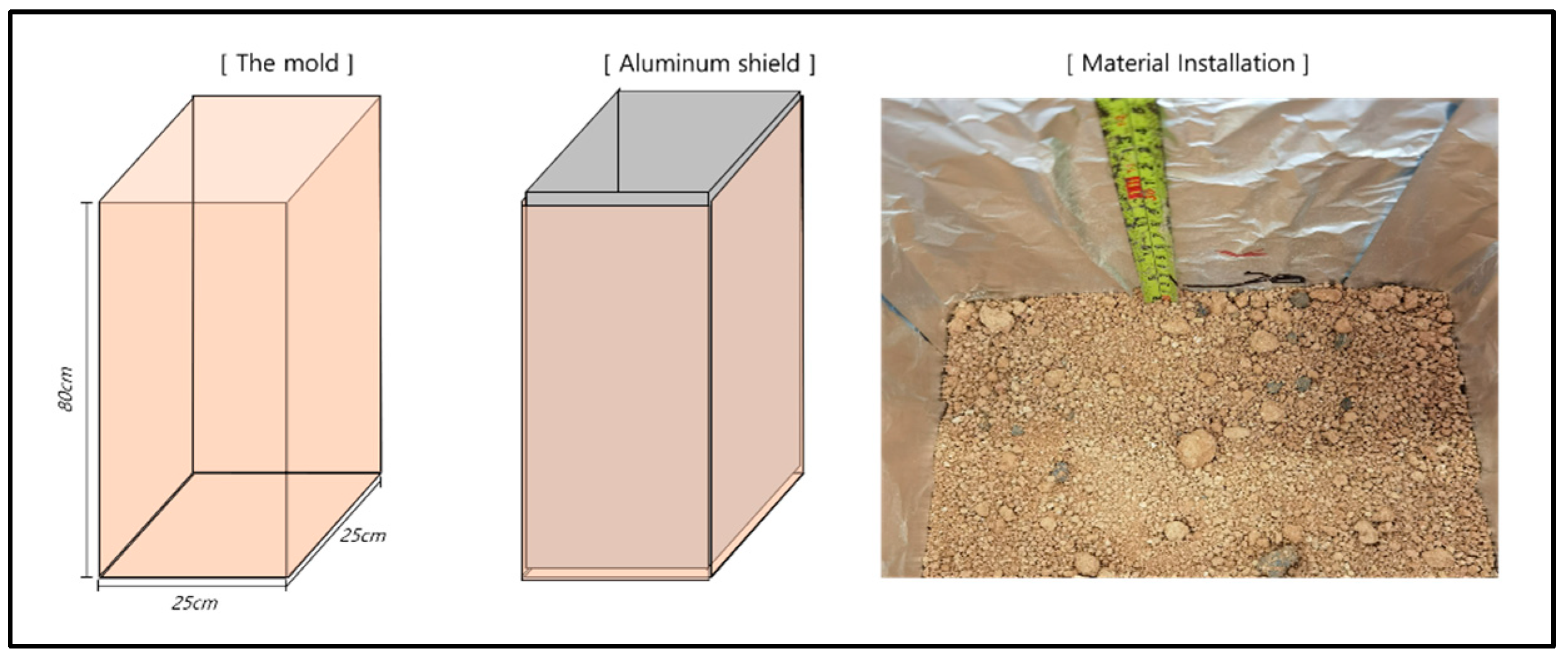
The experiment was conducted by building a mold as shown in Figure 1. It was designed with dimensions of 25 cm × 25 cm × 80 cm and shielded on five sides except for the top with aluminum to prevent electromagnetic waves from being transmitted to the side. Before the experiment, we confirmed that the signal could not be transmitted during aluminum shielding. In the experiment, we performed rammer compaction 25 times for every 10 cm of filler and repeated the measurement 5 times for each experimental condition.

Figure 1.
A scheme of experimental setup.
To check the maximum depth of reach of the signal, we fixed the surface thickness of the cold mix asphalt at 10 cm and changed the thickness of the subgrade soil (yellow soil) from 20 cm to 70 cm by 10 cm. Simultaneously, we installed the tag into six levels from 30 cm to 80 cm. As an experimental cross-section for analyzing signal attenuation according to the type of material, the surface layer maintained a thickness of 10 cm; however, the thickness of the material was set to 15 cm, 30 cm, 45 cm, and 60 cm (four levels).
Assuming that the underground utility does not reach the auxiliary base layer and road surface as the depth of the underground utility is limited when applying the trench method, three types of fillers were selected: subgrade soil, sand, and graded gravel materials. Assuming that the excavation width is 25 cm and there is no effect due to reflection or scattering of electromagnetic waves that may occur at the cutting interface, we considered only electromagnetic waves that reach straight. The decision variable for evaluating the moisture effect was limited to the moisture ratio. We controlled the surface layer thickness to 10 cm and the subgrade soil filler thickness to 25 cm. Only the moisture ratio conditions varied from dry (<8%) to optimum (8–20%) or saturated (>20%). Finally, to verify the applicability in the case of the increase or decrease in packaging thickness due to construction error and maintenance, we experimented by varying the thickness of the surface layer and the subgrade soil filler. We set the surface layer depth to 5 cm, 10 cm, 15 cm, and 20 cm and the filler depth to 20 cm, 25 cm, 30 cm, and 35 cm.
The cold mix asphalt that is a commercial product was applied for the surface layer. Its volume density was relatively low at 1.15 to 1.25 g/cm3 compared to other materials. The density of the subgrade soil used as a filler was 1.6 g/cm3. We expected the soil close to the clay to have a significant impact on electromagnetic wave attenuation. The sand density was 1.54 g/cm3 and belonged to coarse sand based on the fitness modulus (3.22%) and particle size distribution.
The graded gravel material was granite with a maximum aggregate size of 31.5 mm, which can be classified as a permeable base material that does not contain fine aggregate (Figure 2). The design strength and air volume of mortar were 23 MPa and 4.9%, respectively, and the ratio of cement, sand, and water was 1:3:0.5 (weight ratio). We used the same sand and typical Type I cement.
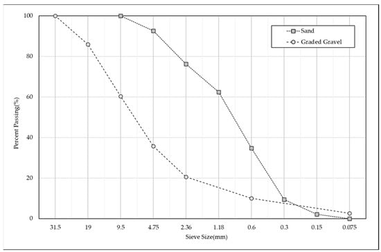
Figure 2.
Experimental results of sieving sand and graded gravel.
4. Results
Based on the maximum reach experiment results, we confirmed that the signal reach failed from 69 cm. Figure 3 shows the measured value and average value of RSSI for each installation depth simultaneously. The measurement error was less than 2 dBm. All indoor experiments had the same measurement error. The average RSSI at the shallowest depth (30 cm) was −65.8 dBm, and the average RSSI at the depth at which the signal finally reached 68 cm was −77.2 dBm. The signal attenuation width decreased with increasing installation depth.
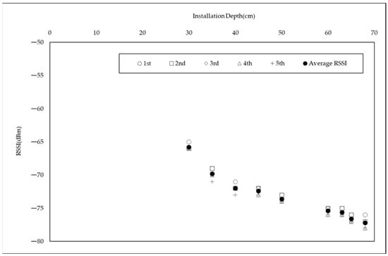
Figure 3.
Experimental results of the maximum depth of signal.
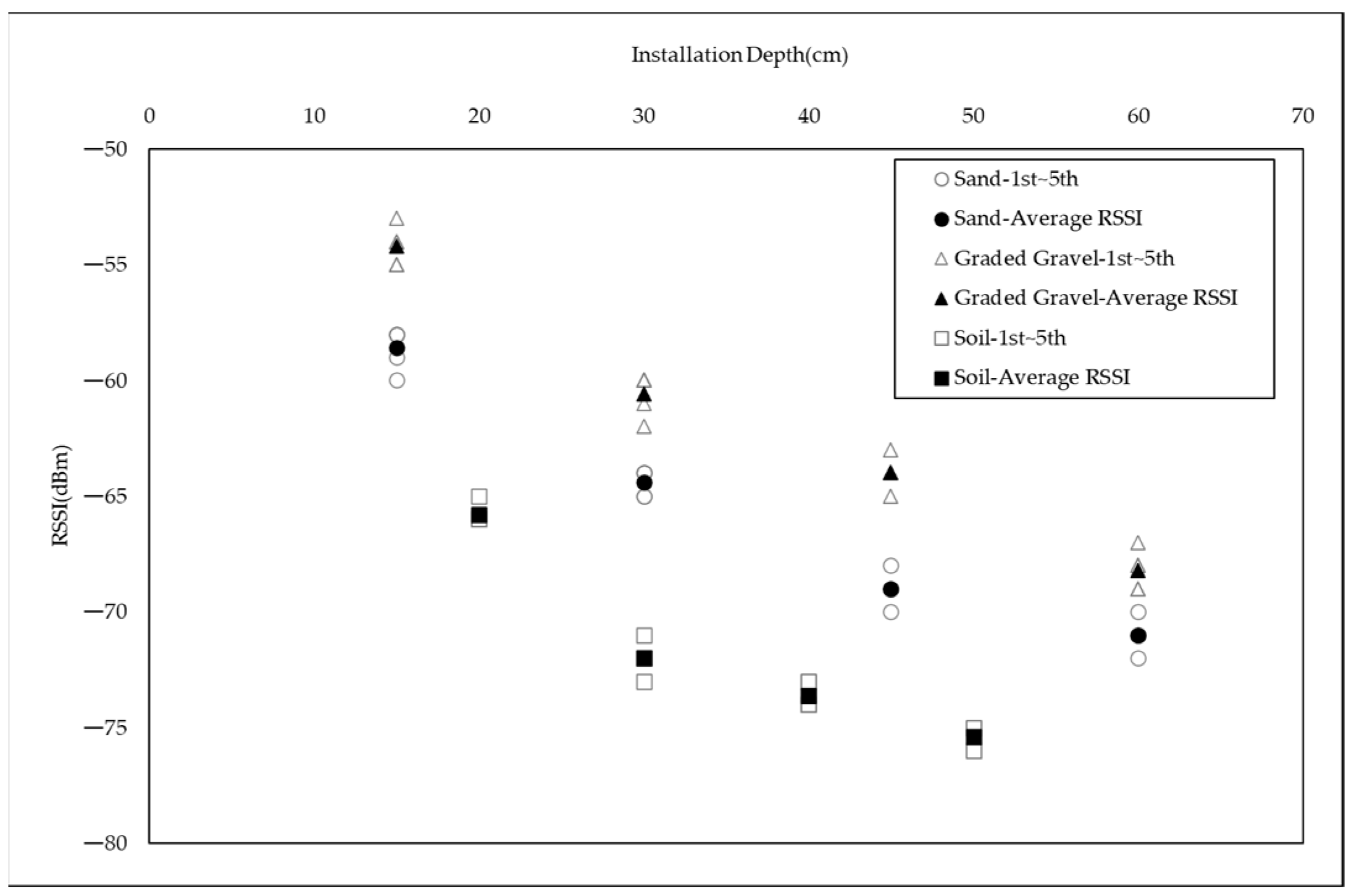
Based on the comparison results of signal attenuation according to the filler, attenuation in subgrade soil was the largest (Figure 4). For sand, the average RSSI at the shallowest depth (35 cm) was −58.6 dBm, and the average RSSI at the deepest depth (60 cm) was −71.0 dBm. In the case of the graded gravel, the average RSSI at the shallowest and deepest depths were −54.2 dBm and −68.2 dBm, respectively.

Figure 4.
Comparison of signal attenuation of different materials.
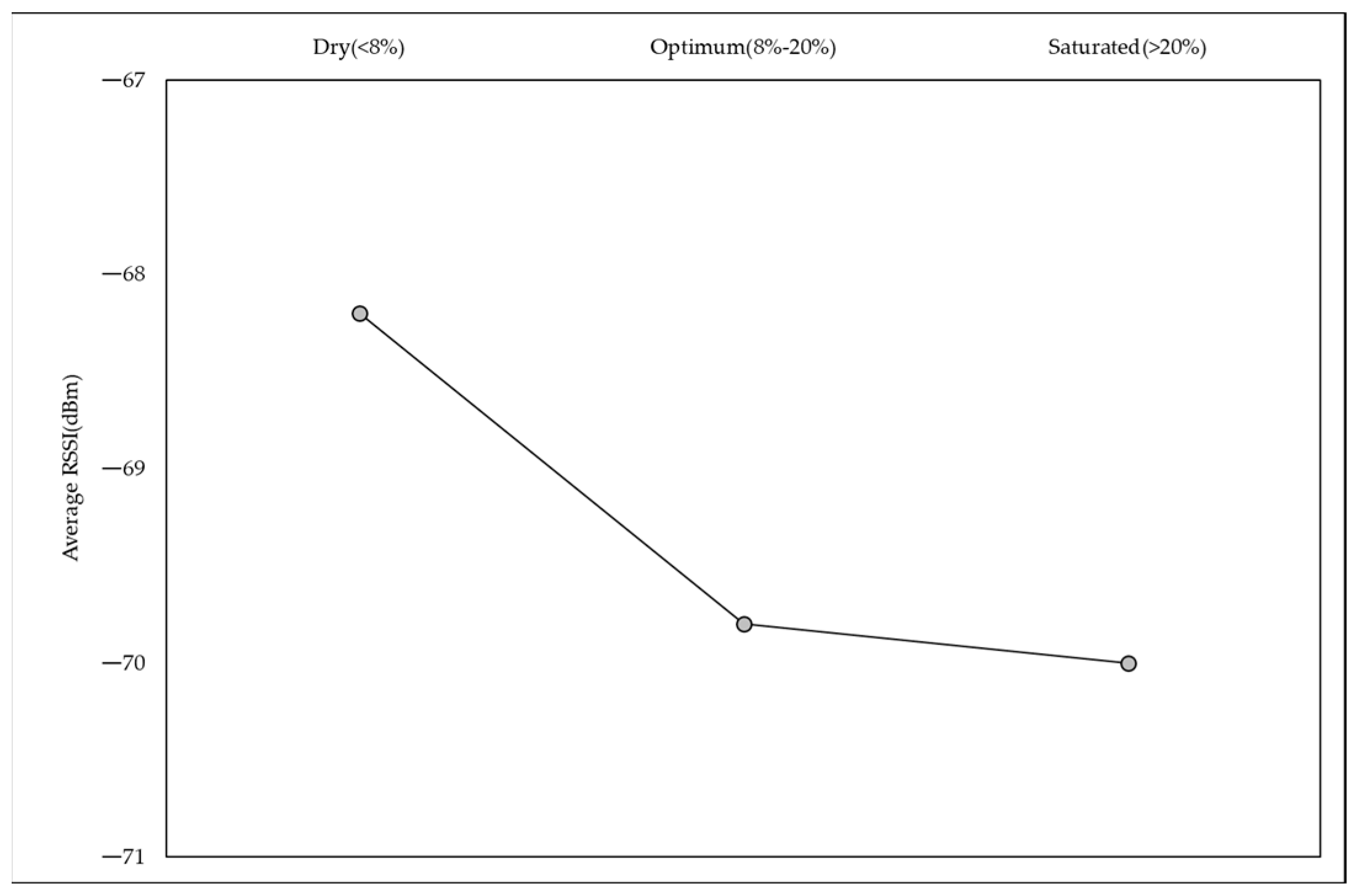
As shown in Figure 5, we observed the signal attenuation based on the moisture content. The RSSI was −68.2 dBm in the dry state and −70.0 dBm in the saturated state. We confirmed the effect of moisture on signal attenuation. We observed a difference of 1.8 dBm depending on the amount of moisture in the 25 cm deep subgrade soil.
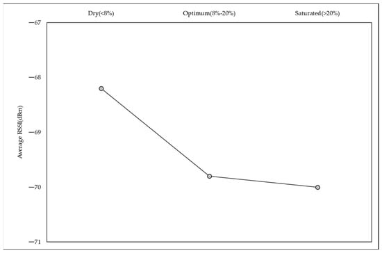
Figure 5.
A plot of signal attenuation by moisture contents.
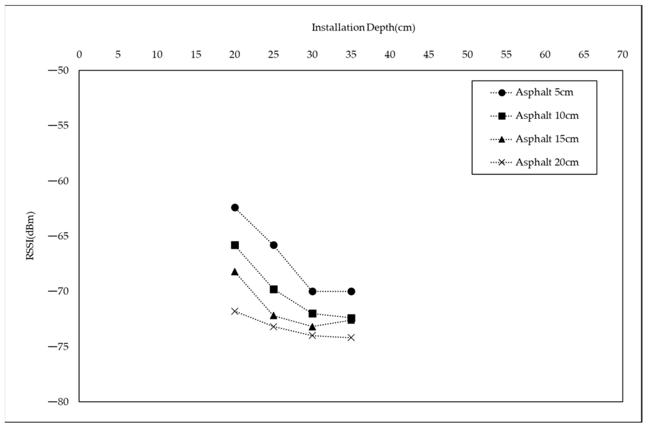
Figure 6 presents the results of the surface layer thickness change experiment in preparation for construction errors. Regardless of the type of medium, the signal attenuation width was large at a shallow depth, and signal intensity converged at a deep depth. Assuming the depth sum of the two layers to be 40 cm when the road surface layer was 20 cm and the asphalt layer was 20 cm, the signal strength was –71.8 dBm. When the asphalt layer was 5 cm and the road surface layer was 35 cm, the signal strength was −70.0 dBm. Based on these results, we can infer that the asphalt layer has a more significant effect on signal attenuation. Construction errors occurring in the field may affect signal attenuation. The depth of installation from the surface is most important.
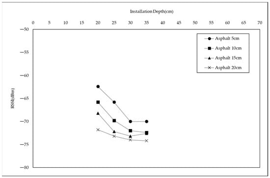
Figure 6.
A test result of surface layer thickness.
5. Discussion and Conclusions
A multilayer structure composed of asphalt pavement and subgrade soil was simulated. The maximum reach of the tag signal was tested through a laboratory experiment. On the basis of limited laboratory test results, the maximum signal reach depth of the tag installed under the pavement structure was 68 cm. This is a performance that satisfies the target design depth of 40–50 cm. Even considering that dBm is a unit of a logarithmic scale, the signal attenuation at shallow depths was rapid, and RSSI levels at 68 cm, 65 cm, 60 cm, and 50 cm close to the limit point had a small width of decline. Based on the results of experiments by material, the signal-reaching performance in the graded gravel was the best. The signal attenuation was the largest in the subgrade soil, and the signal was not received in cement mortar. The difference in signal attenuation between the sand and the graded gravel was larger than the effect of 15 cm depth, and the difference between the subgrade soil and the graded gravel was even greater.
The results showed that the effect was due to the porosity and density of the material. This experiment was conducted for the purpose of testing representative materials used in road structures. If a more precise experiment is performed with the density or void as a variable, design criteria according to the material can be derived. In addition, signal attenuation of 1.8 dBm occurred according to moisture. When using permeable materials, the effect of signal attenuation due to moisture must be considered.
Under the road structure, there are various facilities to provide functions of the city, such as communication lines, power lines, water supply and sewage, gas pipes, and heat transport pipes. Based on the investigation results of the management technology of underground utilities, electromagnetic locator, GPR, and RFID application technology were representative. All three were technologies utilizing electromagnetic waves. However, each had its pros and cons. Among them, UHF RFID tags were selected as an alternative to install on utilities, because they can provide information, have no battery restrictions, and have the least influence on the surrounding environment.
To evaluate the performance and capability of the UHF RFID tag, a laboratory experiment was implemented. The main purpose of the experiment was to determine how deep a signal can reach in a multilayer road structure. According to advanced studies, the effect of signal attenuation is caused by the type and moisture of the medium.
The key achievement of this study is that it reviewed the optimal installation depth. It can be obtained by finding the maximum reach depth of the signal in the road structure. In addition, the effect of signal attenuation according to the materials and moisture was examined. When installing a communication cable by trenching excavation, a suitable material was found that had a higher porosity, and lower moisture.
In particular, conducting reach performance experiments in media primarily used in civil engineering fields, such as soil and asphalt could become a technical foundation for future applications to the underground utility history management system.
Research limitations and further work are suggested as follows. First, it is necessary to overcome the limited experimental variables and lack of mock-up tests through field applications. In addition, theoretical analysis and simulation are needed. Second, signal attenuation should be analyzed considering the properties of each material and the interface. Voids and the density of the material and electromagnetic wave behavior at the different interfaces would affect the signal attenuation. Through this work, it would be possible to theoretically differentiate the characteristics between monolayer and multilayer mediums. Third, it is necessary to analyze the effect of the antenna used with tags. Performance would be different depending on the various antenna type. Finally, to validate practicality, an in situ experiment for investigating the impact of the surrounding environment is required. Interference might be caused by electromagnetic waves generated by the underground facilities such as power lines. Through this further work listed above, this study will eventually contribute to the underground utility management system by proposing an optimum UFH RFID tag system.
Author Contributions
Conceptualization, Y.-H.C.; methodology, Y.G.; validation, W.L. and Y.-H.C.; formal analysis, Y.G.; investigation, Y.J.; resources, W.L.; data curation, Y.J.; writing—original draft preparation, Y.G.; writing—review and editing, Y.J.; visualization, S.R.; supervision, Y.-H.C.; project administration, Y.J.; funding acquisition, Y.J. All authors have read and agreed to the published version of the manuscript.
Funding
This work was supported in part by the Korea Institute of Civil Engineering and Building Technology Research Project (20230117-001 and 20230170-001).
Institutional Review Board Statement
Not applicable.
Informed Consent Statement
Not applicable.
Data Availability Statement
Not applicable.
Conflicts of Interest
The authors declare no conflict of interest.
References
- Lee, S.M.; Yoon, H.M. Improvements in Safety Management for Underground Facilities in Seoul; Policy Research Report; Seoul Institute: Seoul, Republic of Korea, 2020. (In Korean) [Google Scholar]
- Kim, J.W. Case Study on Underground Utilities Damage in Urban Area due to Deep Underground and Administrative Approach to Alleviate Problems. Unpublished Thesis, Hanyang University, Seoul, Republic of Korea, 2019. [Google Scholar]
- Goodrum, P.; Smith, A.; Slaughter, B.; Kari, F. Case study and statistical analysis of utility conflicts on construction roadway projects and best practices in their avoidance. J. Urban Plan. Dev. 2008, 134, 63–70. [Google Scholar] [CrossRef]
- Anspach, J.H. Utility Location and Highway Design: A Synthesis of Highway Practice; Transportation Research Board of National Academies: Washington, DC, USA, 2010. [Google Scholar]
- Korea Institute of Civil Engineering and Building Technology. Development of Technologies and Management Method of Trenching About Aerial Utility Cables for Urban Regeneration. 2018. Available online: https://www.codil.or.kr/viewDtlConRpt.do?gubun=rpt&pMetaCode=OTKCRK190462 (accessed on 5 January 2023).
- Sterling, R.L.; Anspach, J.H.; Allouche, E.N.; Simicevic, J.; Rogers, C.D.; Weston, K.E.; Hayes, K. Encouraging Innovation in Locating and Characterizing Underground Utilities; SHRP2 Transportation Research Board: Washington, DC, USA, 2009. [Google Scholar]
- Radiodetection. The Theory of Buried Cable and Pipe Location. 2017. Available online: https://www.radiodetection.com/en-us/cable-and-pipe-location-theory (accessed on 5 January 2023).
- Daniels, D.J. Ground penetrating radar. In IET Radar, Sonar, Navigation and Avionics Series 15; The Institution of Engineering and Technology: London, UK, 2004. [Google Scholar]
- Jol, H.M. Ground Penetrating Radar Theory and Applications; Elsevier: Amsterdam, The Netherlands, 2008. [Google Scholar]
- Metje, N.; Atkins, P.R.; Brennan, M.J.; Chapman, D.N.; Lim, H.M.; Machell, J.; Muggleton, J.M.; Pennock, S.; Ratcliffe, J.; Redfern, M. Mapping the underworld–state-of-the-art review. Tunn. Undergr. Space Technol. 2007, 22, 568–586. [Google Scholar] [CrossRef]
- Cheng, N.F.; Tang, H.W.; Chan, C.T. Identification and positioning of underground utilities using ground penetrating radar (GPR). Sustain. Environ. Res. 2013, 23, 141–152. [Google Scholar]
- North, D. RFID markers and GPS technology support Virginia DOT roadway construction. Proj. Case Study Rep. USA 2010, 38–39. [Google Scholar]
- Nikitin, P.V.; Rao, K.V.S.; Lazar, S. An Overview of Near Field UHF RFID. In Proceedings of the 2007 IEEE International Conference on RFID, Grapevine, TX, USA, 26–28 March 2007; IEEE: Piscataway, NJ, USA, 2007; pp. 167–174. [Google Scholar] [CrossRef]
- Dobkin, D.M.; Weigand, S.M. Environmental effects on RFID tag antennas. In Proceedings of the IEEE MTT-S International Microwave Symposium Digest, Long Beach, CA, USA, 17 June 2005; IEEE: Piscataway, NJ, USA, 2005; pp. 135–138. [Google Scholar] [CrossRef]
- Park, D.; Kwak, K.; Chung, W.K.; Kim, J. Development of underwater distance sensor using EM wave attenuation. In Proceedings of the 2013 IEEE International Conference on Robotics and Automation, Karlsruhe, Germany, 6–10 May 2013; IEEE: Piscataway, NJ, USA, 2013; pp. 5125–5130. [Google Scholar] [CrossRef]
- Rao, K.V.S.; Nikitin, P.V.; Lam, S.F. Antenna design for UHF RFID tags: A review and a practical application. IEEE Trans. Antennas Propag. 2005, 53, 3870–3876. [Google Scholar] [CrossRef]
- Park, D.; Kwak, K.; Chung, W.K.; Kim, J. Development of Underwater Short-Range Sensor Using Electromagnetic Wave Attenuation. IEEE J. Ocean. Eng. 2016, 2, 318–325. [Google Scholar] [CrossRef]
- Ali, G.; Burcin, B.G.; Burak, G.; Shuai, L.; Nan, L. Analysis of the variability of RSSI values for active RFID-based indoor applications. Turk. J. Eng. Environ. Sci. 2013, 37, 186–210. [Google Scholar] [CrossRef]
- Shin, E.C.; Park, K.S.; Park, J.J. A fundamental experiment for field application of the under pavement cavity management system using RFID. J. Soc. Disaster Inf. 2019, 15, 391–401. [Google Scholar] [CrossRef]
- Cassidy, N.J.; Jol, H.M. Ground penetrating radar data processing, modelling and analysis. In Ground Penetrating Radar: Theory and Applications; Jol, H.M., Ed.; Elsevier: Amsterdam, The Netherlands, 2009; pp. 141–176. [Google Scholar] [CrossRef]
- Hipp, J.E. Soil electromagnetic parameters as functions of frequency, soil density, and soil moisture. Proc. IEEE 1974, 62, 98–103. [Google Scholar] [CrossRef]
- Cassidy, N.J. Frequency-dependent attenuation and velocity characteristics of nano-to-micro scale, lossy, magnetite-rich materials. Near Surf. Geophys. 2008, 6, 341–354. [Google Scholar] [CrossRef]
- ISO/IEC 18000-6:2010; Information technology—Radio frequency identification for item management—Part 6: Parameters for air interface communications at 860 MHz to 960 MHz. International Organization for Standardization: Geneva, Switzerland, 2010.
Disclaimer/Publisher’s Note: The statements, opinions and data contained in all publications are solely tose of the individual author(s) and contributor(s) and not of MDPI and/or the editor(s). MDPI and/or the editor(s) disclaim responsibility for any injury to people or property resulting from any ideas, methods, instructions or products referred to in the content. |


Disclaimer/Publisher’s Note: The statements, opinions and data contained in all publications are solely those of the individual author(s) and contributor(s) and not of MDPI and/or the editor(s). MDPI and/or the editor(s) disclaim responsibility for any injury to people or property resulting from any ideas, methods, instructions or products referred to in the content. |
© 2023 by the authors. Licensee MDPI, Basel, Switzerland. This article is an open access article distributed under the terms and conditions of the Creative Commons Attribution (CC BY) license (https://creativecommons.org/licenses/by/4.0/).