Article

Analysis of Foundation Pit Excavation Deformation and Parameter Influence of Pile-Anchor-Ribbed-Beam Support System

1
Hunan Engineering Research Center of Structural Safety and Disaster Prevention for Urban Underground Infrastructure, Hunan City University, Yiyang 413000, China
2
School of Civil Engineering, Central South University, Changsha 410075, China
*
Author to whom correspondence should be addressed.
Appl. Sci. 2023, 13(4), 2379; https://doi.org/10.3390/app13042379
Submission received: 31 December 2022 / Revised: 6 February 2023 / Accepted: 9 February 2023 / Published: 13 February 2023
(This article belongs to the Special Issue Advances in Sustainable Geotechnical Engineering)

Abstract

:
The support system is the most important part of foundation pit engineering, which mainly determines the safety of foundation pit engineering. Based on the characteristics of the foundation pit of Changsha international financial center, the original pile-anchor-beam (PAB) support system is improved into a new form of support system, the pile-anchor-ribbed-beam (PARB) support system. This study establishes a numerical simulation model to calculate the surface settlement and the deformation of the retaining structure caused by the excavation of the foundation pit by using the PAB and PARB support systems, respectively. Finally, this study analyzes the influence of pile anchorage depth, ribbed beam size and waist beam size on the support effect. The field monitoring data are in good agreement with the numerical simulation results, which verifies the validity and accuracy of the numerical calculation model. The support effect of the new PARB support system is 30% higher than that of the original PAB support system. The position of maximum surface settlement is about 0.5 times the excavation depth from the retaining structure, and the position of maximum lateral deformation of the pile is about 0.9 times the excavation depth from the pile top. The increase in pile embedded depth and ribbed beam size can significantly improve the support effect, while the change of waist beam size does not improve the support effect significantly.

1. Introduction

With the rapid development of the urban economy, infrastructure construction is in full swing. Because of the limited space for urban construction, high-rise buildings have become an indispensable part of urban buildings. High-rise buildings have very strict requirements for settlement control and need strong foundations to provide enough support effect. Thus, a large number of deep foundation pit engineering methods are launched in urban cities. The retaining structure is generally made for the provisional project, but if the support system is not applicable to deep foundation pit engineering, serious accidents may occur abruptly, causing damage to people and the economy.
Common foundation pit support systems include the diaphragm wall and internal support structure, soil nailing wall, cement gravity wall, steel mixing wall (SMW method), cast-in-place pile wall, etc. The diaphragm wall and internal support system and steel mixing wall systems are generally used for subway station engineering. Those support structures are applicable to long deep foundation pits, which can effectively control the disturbance of foundation pit excavation to the surrounding environment [1,2]. The soil nailing wall and cement gravity wall systems are generally applicable to foundation pits with small excavation depths but large excavation areas, whose internal support does not resist soil deformation [3,4,5]. The cast-in-place pile wall system is applicable to deep foundation pits with large excavation areas [6,7]. The cast-in-place pile and anchor cable (pole) support is an improved support system based on the cast-in-place pile wall, in which the anchor bolt and the anti-slide pile provide anchoring force and sliding resistance force to jointly resist the sliding of the soil behind the support. The cast-in-place pile and anchor cable (pole) support system is favored by designers and scholars, because of its good support effect and stability. Many scholars have studied the disturbance effect of foundation pit excavation by the cast-in-place pile and anchor cable (pole) support system in laboratory tests, numerical simulation, on-site monitoring, etc. Liu, et al. [8] presented a complete case record of a deep foundation pit with pile-anchor retaining structure excavated in red sandstone stratum, and established an FEM to analyze the additional stress and deformation induced by the excavation. Both the measured and numerical simulation results show that the deformation of the pile-anchor supported deep excavation is significantly affected by the spatial effect. Cui et al. [9], based on the analysis of the deformation data of a pile-anchor supporting a deep foundation pit in Harbin, obtained from monitoring during the winter, investigated the influence of freezing and thawing cycles. The results show that the horizontal displacement in the middle of the shallow layer of the foundation pit is significantly larger than that on both sides during the freeze–thaw cycles, and the spatial effect becomes noticeable. Su et al. [10] designed a large model test for a foundation pit supported by a pile-anchor with a geometric similarity ratio of 1:10 to study the force and deformation characteristics of the support structure. The test results show that for the pile-anchor support structure, the anchors have significant limiting effects on the displacement of the piles. Liu et al. [11] used physical model tests to study the deformation law of the piles and the surrounding soil during the excavation of the deep foundation pit, revealing the variation law of earth pressure in time and space in the pit and then verified it by numerical simulation. The result show that the embedded depth has a significant effect on the deformation and earth pressure distribution of the foundation pit. Maleki et al. [12] carried out a large number of parametric studies considering all aspects of soil–structure interaction or different excavation geometries to find the optimal design. Finally, a simple equation was developed that can predict the deflections caused by deep excavations. Zhao et al. [13] used a PLAXIS-based finite element method to reveal the crucial mechanical behaviors of the retaining structure and soil layers as a result of different types of anchorage failures. According to the simulation results, the responses to anchorage failures were analyzed, and the safety coefficient for the retaining structure was presented. The analysis for this numerical work indicates that dangerous failure positions appear at the top of the pile wall or in the region near the excavation bottom. From the above research, the study of pile support systems and the cast-in-place pile and anchor cable support system for deep foundation pits are very abundant. Scholars focus on the pile and soil interaction mechanism, pile and anchor interaction mechanism and the influence of support parameters on the stability of foundation pits. For the ultra-deep foundation pit, whether the cast-in-place piles and anchor cable support system can meet the deformation control requirements remains to be discussed.
Based on a foundation pit with depth of 35 m of Changsha international financial center, this article analyzes the shortcomings of the pile-anchor-beam (PAB) support system and then proposes a new pile-anchor-ribbed-beam (PARB) support system. This study establishes a numerical simulation model to calculate the control effects of the two support systems. Finally, the influence of pile embedded depth, ribbed beam size and waist beam size on the support effect of the PARB support system is analyzed. The research results can provide reference for the design of a pile and anchor retaining structure for deep foundation pits.

2. Project Profile

2.1. Engineering Background

Changsha international financial center is the highest building in Hunan Province of China, with the maximum height of 452 m. The excavation depth of the foundation pit is 31.80 m, and the area of the foundation pit is 76,700 m2, which is a deep and large foundation pit. There is a 17-floor high-rise building on the east side of the north sidewall and a 24-floor high-rise building on the west side of the north sidewall. The location of those two existing high-rise buildings is shown in Figure 1. The south side wall is about 488 m long, and there is a 34-floor high-rise building on the west side of the south side wall. The safety level of the side wall of the foundation pit is Level I and the structural importance coefficient is 1.1. The shape of the foundation pit is basically rectangular. The lengths of the east, south, west and north side walls of the foundation pit are about 168, 488, 136 and 546 m, respectively, as shown in Figure 1.
The stratum around the foundation pit is composed of artificial fill, muddy silty clay, silty fine sand, medium-coarse sand and other stratum with poor self-stability and low impermeability. At the same time, a densely populated city is near the foundation pit. The existing buildings, roads and underground pipes are close to the foundation pit. The stratum of the foundation pit has poor stability, and if the retaining structure of foundation pit is unstable, severe disasters may occur.
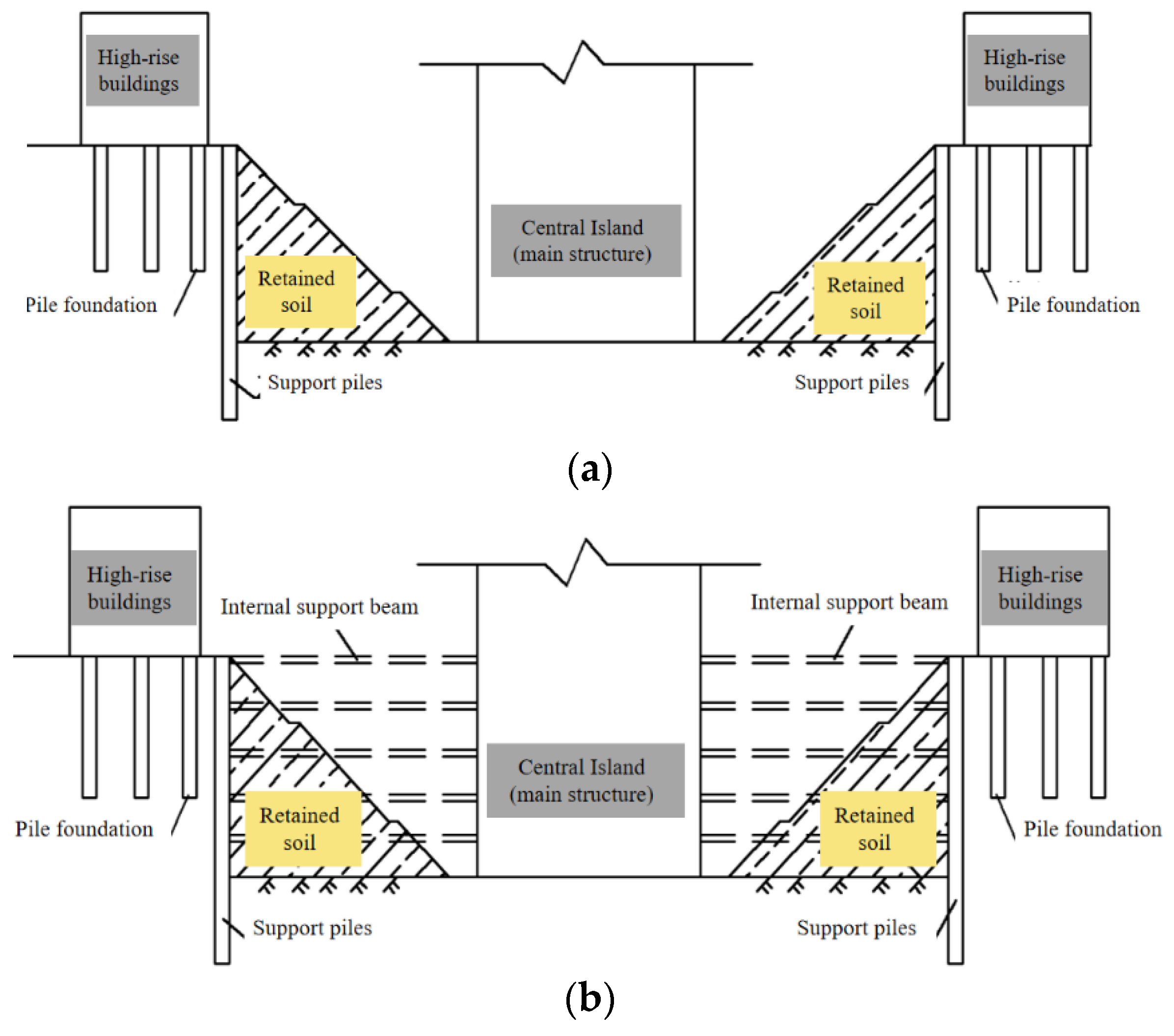
The internal support or reverse construction method is generally adopted for deep foundation pit in city centers. However, due to the irregular shape of the foundation pit, the use of internal support may have great risks and high cost, which cannot meet the construction requirements. Through the comparison of technology, economy, environmental protection and so on, the support system of this foundation pit is the pile and anchor support system. The reverse construction method of central island is adopted in two phases. The specific construction scheme is as follows:
Phase 1 of project (Figure 2a): The pile-anchor support system is adopted in the area without high-rise buildings around the foundation pit. Piles are constructed for the foundation pit near the three high-rise buildings, and the soil mass is retained by the support system of sloping and soil nailing wall to ensure the safety of the three high-rise buildings.
Phase 2 of project (Figure 2b): After Phase 1 of project is completed and the main structure forms a “central island”, the foundation pit near the three high-rise buildings will be excavated and supported. Based on the piles constructed in Phase 1, the foundation pit support construction and main structure construction are established by the semi-reverse construction method or internal support construction technology. The construction process of the foundation pit is shown in Figure 2.
The deformation of the retaining structure is the main reflection of the deformation of the surrounding strata, pipelines, roads and buildings [14,15]. It is particularly important to clarify the relationship between the displacement of the retaining structure and the excavation depth. Therefore, during the excavation of foundation pit, the main monitoring objects are the lateral and vertical deformation of the slope top, the surface subsidence and the lateral deformation of the pile.
(1) Horizontal and vertical displacement monitoring of slope top: The monitoring points can be arranged at the top of the wall with a spacing of 15 m.
(2) Ground surface subsidence monitoring: The monitoring points can be arranged on the side close to the foundation pit. The monitoring points are suspended on both sides of the road where they will not affect the traffic and are convenient for preservation with a spacing of 25 m. Obtaining more information on road settlement, the road observation points are staggered from the pipeline settlement monitoring points on both sides of the road. Sampling observation is adopted for municipal underground pipelines. According to the control requirements, the maximum ground surface settlement caused by the excavation is limited to 20 mm.
(3) Deep lateral displacement of slope monitoring: The deep lateral displacement of slope can be monitored by inclinometer, which consists of clinometer pipe, clinometer and digital reading instrument. The clinometer can be arranged with one monitoring point every 20 m along the 1.0 m depth of the wall top. According to the control requirements, the maximum lateral displacement caused by the excavation is limited in 30 mm.
During the survey, no groundwater was encountered in the borehole of this pit node site. The foundation excavation stratum is mainly powder clay, and its permeability coefficient is only 0.001 m/d, so the permeability is very low. Therefore, there is less precipitation in this foundation excavation project, and the influence of foundation precipitation is negligible in theoretical calculation and numerical simulation.

2.2. Original Composite Support Structure of Pile-Anchor-Beam (PAB)

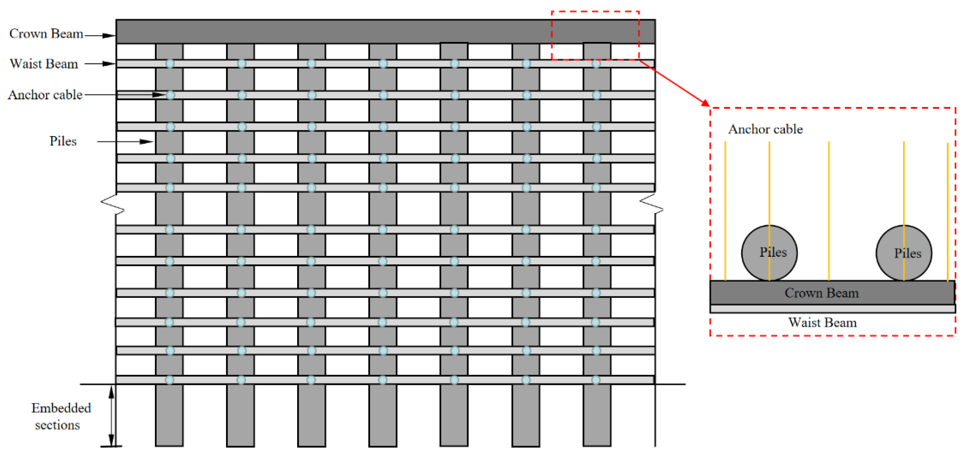
In the original composite support structure of pile, anchor and beam, pile refers to the row of piles along the depth direction, anchor refers to the anchor cable or anchor rod set between piles, and beam refers to the crown beam at the top of pile row and the waist beam set transversely, as shown in Figure 3. The soil pressure directly acts on the pile, which resists the soil sliding and deformation through its stiffness and the resistance load of the anchor cable. The main functions of the waist beam are to strengthen the connection between piles to ensure the deformation coordination between rows of piles and strengthen the integrity of the support system.

2.3. New Composite Support Structure of Pile-Anchor-Ribbed-Beam (PARB)

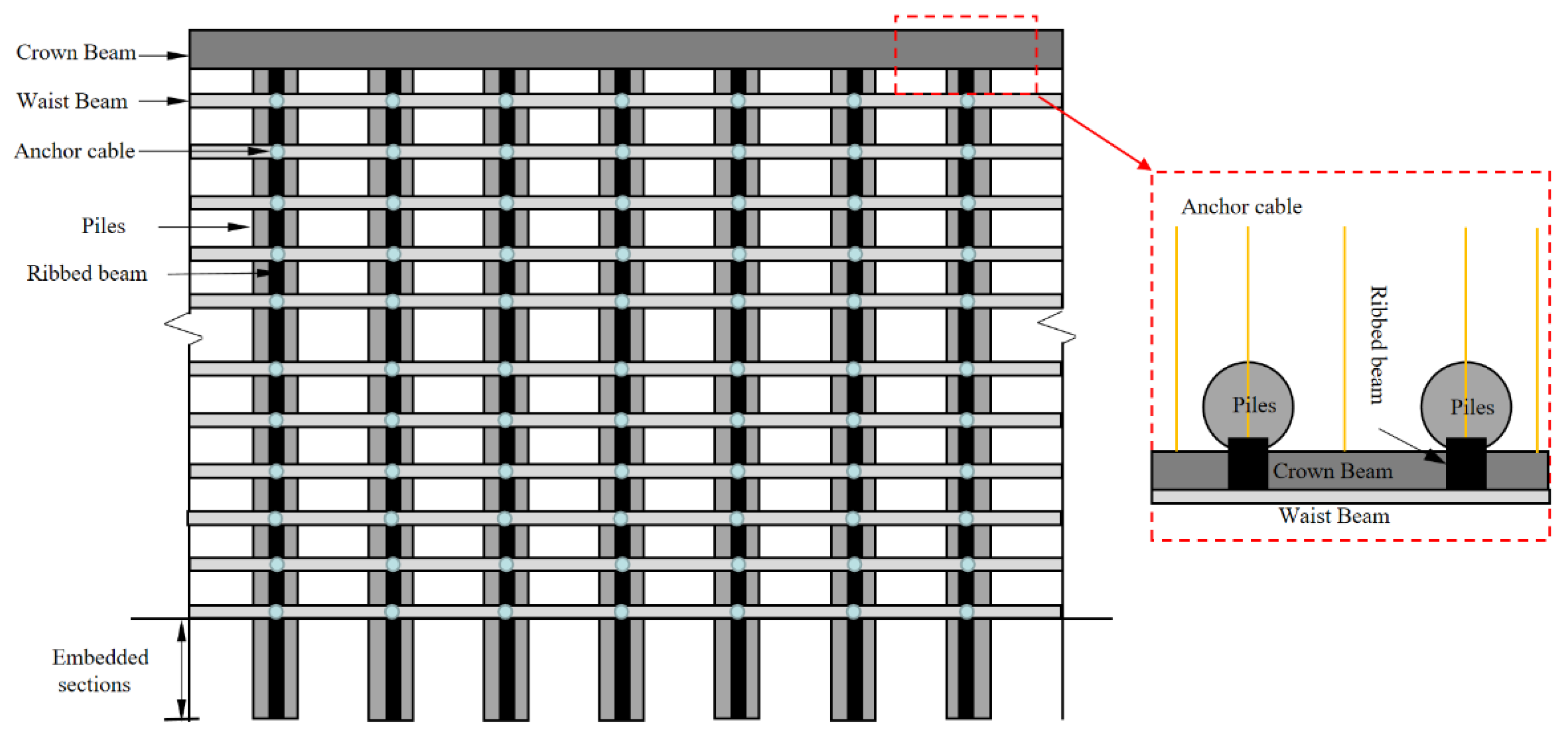
The original composite structure of the cast-in-place pile and anchor cable system is improved for this project. The improved support structure is still composed of row piles, anchor cables (pole) and beams. The beams in PARB have two meanings, which are different from PAB. First, the beams refer to the crown beam at the top of the row piles and the waist beam set transversely, which is consistent with the original support system. Secondly, the beams refer to the ribbed beam in the row of piles inclined to the inner side of the foundation pit, as shown in Figure 4.
The waist beam is mainly used to provide an anchor end for the anchor cable (pole) and transfer the tension force of the anchor cable to the row piles in PAB. The waist beam and row piles are cast separately and there is only a simple bond between them, which can only ensure that the waist beam will not slide down along the row piles. However, row piles can be equivalent to special-shaped piles or T-shaped piles in PARB. Although the ribbed beam and piles are cast separately, the ribbed beam and the waist beam are cast at the same time. The ribbed beam and the waist beam are rigidly connected with the piles, which is equivalent to forming an integral truss structural panel. The anchor cable is integrated with the truss beam through the anchor head. This construction method greatly improves the overall stiffness of the support structure, strengthens its stability and effectively resists the displacement of the waist beam and anchor cable, which ultimately makes the row piles, anchor cables, waist beam and ribbed beam piles form an integrated support system.
To sum up, the original PAB support system is only a simple combination of pile, anchor and beam, so it does not form an integral support structure. Conversely, the new PARB support system proposed in this project realizes the integral combination of pile, anchor and beam. Therefore, the original PAB support system can only be regarded as composite support system of pile and anchor (or pile, anchor and beam) strictly, while PARB is more appropriate.

3. Numerical Simulation Model

3.1. Calculation Assumptions

This study uses ABAQUS to simulate the excavation steps of the foundation pit. The three-dimensional model of the foundation pit follows these assumptions: First of all, the materials are considered to be uniform in the three-dimensional model, and the strata are uniformly distributed [16,17]. The plane shape of the foundation pit is irregular, and the PARB is only used in the side of foundation pit near the road. Considering computing time of the numerical simulation model for the whole foundation pit, the model in this study only focuses on the location with the PARB support system, as shown in Figure 1 by the red mark. Then, the impact of groundwater permeability and variation is not considered, and the initial geo-stress field is assumed to be the self-weight stress field, without considering the changes caused by the construction of the retaining structure. Finally, it is assumed that the excavation of the foundation pit and the application of the supporting structure are carried out layer by layer, which indicates that there is no phenomenon of simultaneous multilayer construction.

3.2. Model Size and Boundary Conditions

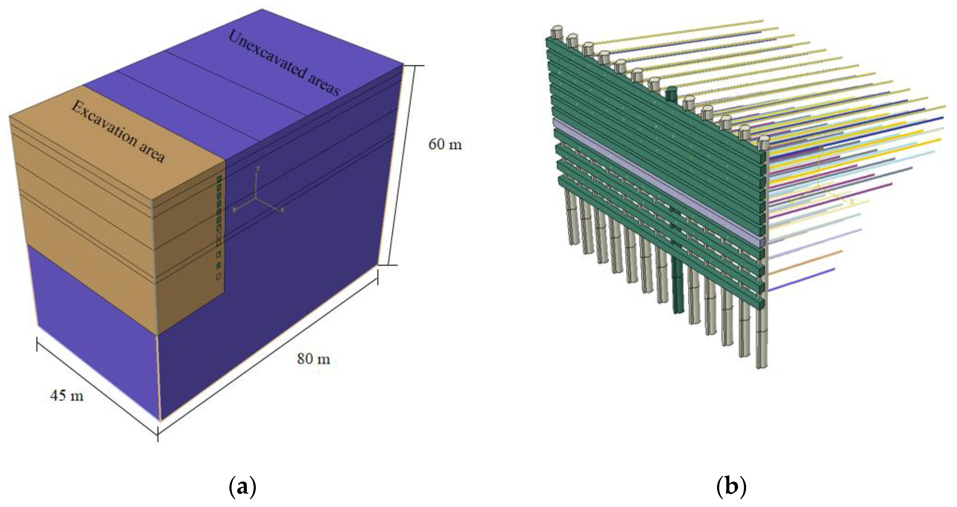
According to the selected research area, the size of the numerical simulation model is 45 m × 80 m × 60 m, in which the excavation area of foundation pit is 45 m × 20 m × 34 m. The diameter of the cast-in-place pile is 1.4 m, the length is 40 m and the embedded depth in soil is 6 m. The size of the crown beam and waist beam in pile top is 1.0 m × 1.4 m × 45 m, and the size of the ribbed beam of the pile is 0.4 m × 40 m × 0.4 m. The soil is divided into 6 layers along its depth in the model with thicknesses of 2.0 m, 2.2 m, 7.6 m, 7.0 m, 1.5 m and 39.7 m. The piles are formed in a single pour as a whole on-site, so there is no connection between the distribution of the piles and the strata. The waist beam is of uniform size, and the size of the waist beam does not change with the soil conditions and burial depth. A total of 12 waist beams and anchor cables in each layer are arranged on the cast-in-place pile. The arrangement and prestress of anchor cables are shown in Table 1. The numerical simulation model is shown in Figure 5. The boundary conditions of the model are as follows: fixed constraint at the bottom surface, normal displacement constraint at the side and free boundary at the top surface. Since the top of the foundation pit is adjacent to the road, the road load effect is considered. A vertical uniform load of 30 kPa is applied within the range of 5–25 m on the top of the foundation pit to simulate the road load.

3.3. Material Constitutions and Parameters

The numerical simulation model consists of the stratum and retaining structure. In the assumptions above, the stratum is assumed to be isotropic and continuous, and its constitutive model adopts the Mohr–Coulomb model [18,19]. Stratum material parameters are determined according to geological exploration data and laboratory test, as shown in Table 2.
The retaining structure includes the cast-in-place pile, waist beam, ribbed beam, crown beam and anchor cable. The cable element of the software is used to simulate the anchor cable.
Conventional elastic or elastic–plastic models cannot clarify the constitutive model of concrete, while the constitutive model combined with damage mechanics can clarify the physical properties of concrete. In Abaqus, the Concrete Damaged Plasticity model was developed by J. Lubliner, J. Lee and G.L. Fenves [19,20,21,22]; its abbreviated form is the CDP model. A large number of studies show that the CDP model is applicable to concrete materials and can reflect the characteristics of the loading curve of concrete. Therefore, the CDP model is adopted for the concrete constitutive model in this study [23,24].
The stiffness degradation of concrete materials under uniaxial tension and compression is defined by two independent uniaxial damage variables, namely the tensile damage factor Dt and the compressive damage factor Dc. The stress–strain relationship for concrete materials in tension and compression are shown in Figure 6, and the corresponding mathematical expressions of the intrinsic model are as follows:
σ t   =   ( 1     D t ) E 0 t ( ε t     ε t p )
σ c   =   ( 1     D c ) E 0 c ( ε c     ε c p )
where σt and σc are the tension stress and compressive stress, respectively; Dt and Dc are tensile and compressive damage parameters, respectively; E0t and E0c are initial tensile and compressive elasticity tensor, respectively; εt and εc are total tension strain tensor and total compressive strain tensor, respectively; εtp and εcp are tensile and compressive plastic strain tensors, respectively.
This constitutive model is often used to simulate the concrete materials in the structure. The parameters of the retaining structure are shown in Table 3.
The contact surface is set between the cast-in-place pile and soil. According to existing research, the contact mode between pile and soil is embedded contact. The contact modes between pile above the bottom of the foundation pit and soil are normal hard contact and tangential friction contact, and the friction coefficient is 0.8 [25,26,27]. The contact mode between the anchor cable and soil is embedded contact. The waist beam, ribbed beam, crown beam and cast-in-place pile are established as a whole model, which are embedded into each other, and the sliding among them is not considered. For the PAB support system, the contact modes between the waist beam and the row of piles are normal hard contact and tangential friction contact. The friction coefficient is taken as 0.5 [28,29,30] to ensure that there is no relative sliding between the waist beam and the row of piles.

3.4. Calculation Process

The calculation process of the model is mainly divided into three parts: geostress balance, supporting and soil excavation [31]. Soil excavation and anchor cable supporting is carried out step by step. The specific calculation process is described as follows:
Step 1: Assign the corresponding material parameters along the depth to the soil, and run the geostatic step.
Step 2: Clear the displacement field in step 1, assign the corresponding element parameters to the cast-in-place pile and activate the contact surface between pile and soil.
Step 3: Excavate soil at the depth of 0–3 m, assign the element parameters to the 1st layer of waist beam, and activate the 1st layer of anchor cable element at the same time.
Step 4–Step 11: Excavate soil at the depth of 3–19 m and excavate 2 m downward each step. Assign the element parameters to the 2nd to 9th layers of the waist beam, and activate the anchor cable element in the 2nd to 9th layers.
Step 12–Step 15: Excavate soil at the depth of 19–28 m, and excavate 3 m downward each step. Assign the element parameters to the 10th–13th layers of the waist beam, and activate the anchor cable elements of the 10th–13th layers.
Step 16: Excavate soil at the depth of 28–34 m and complete the simulation of excavation and supporting steps.
The excavation steps and depth of the foundation pit are consistent with the actual construction on-site.

4. Analysis of Calculation Results

The surrounding surface settlement and the deformation of the retaining structure in this foundation pit should be strictly controlled. Therefore, the numerical simulation results focus on the surface settlement, the lateral deformation of the retaining structure and the maximum settlement of the pile top to analyze the support effect of the PARB support system. The numerical simulation model adopts excavation steps consistent with the on-site construction, resulting in a large amount of calculation data, which is not conducive to comparative analysis. Therefore, this study only extracts the calculation results of three steps: the first step of foundation pit excavation, excavation to half of the depth of the foundation pit and excavation to the bottom of the foundation pit.

4.1. Surface Settlement

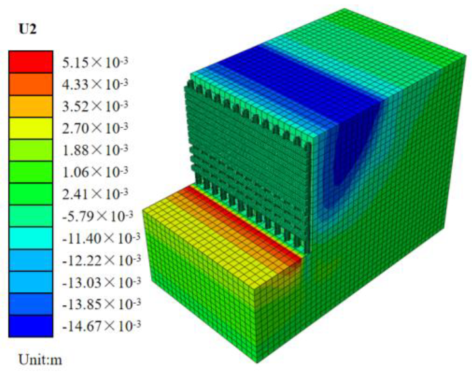
As shown in Figure 7, the deformation of the retaining structure is caused by the unloading effect of soil excavation, resulting in the settlement of the soil behind the retaining structure. Soil inside the foundation pit has uplift deformation, because its consolidation stress is greater than the self-weight stress due to the excavation of the upper soil. The maximum surface settlement is 14.67 mm, and the maximum uplift deformation of soil inside the foundation pit is 5.15 mm. Those deformations are both within the safety control range, which has a high degree of redundancy with the control limit value. The numerical simulation results show that the control effect of the PARB support system is reliable.
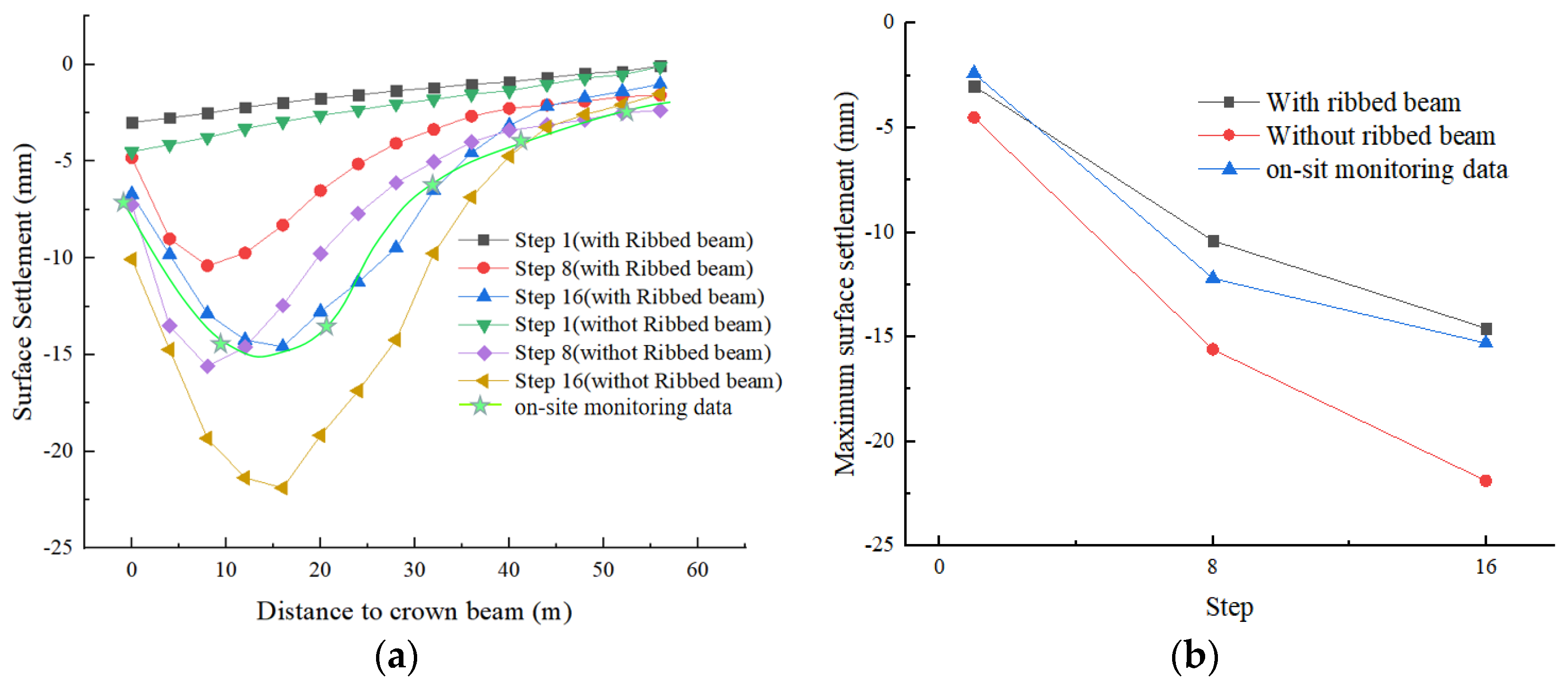
Figure 8a,b shows the curve of surface settlement at the top of slope and the curve of maximum surface settlement with excavation steps. It shows that the following information:
(1) When excavating to the bottom of the foundation pit, the field monitoring data show that the maximum surface settlement is about 15.2 mm, while the numerical simulation result is about 14.7 mm, with an error of about 4%. The position of the maximum surface settlement is about 12 m away from the pile top, while the numerical simulation result is about 16 m away from the pile top. The heterogeneous distribution of the strata may be the main reason for the difference in the maximum settlement position. Both the field monitoring data and the numerical simulation results show that the surface settlement curve presents in the shape of a “V”. The distribution laws of both results are the same, and the calculation error is small, which verifies the correctness of this numerical simulation model.
(2) When excavating the soil to 3 m of depth (Step 1), the surface settlement increases when the distance from the monitoring point to the retaining structure decreases. When excavating to deep soil (Step 2 and Step 3), the surface settlement curve presents in the shape of a “V”. The surface settlement value first increases and then decreases. The distance from the maximum settlement point of the surface to the retaining structure is about one-half of the excavation depth. From the settlement distribution, the main influence range of the settlement trough is concentrated within the range of the excavation depth, and the surface settlement is not obvious beyond this range. Therefore, it is suggested to monitor the development of surface settlement within the range of the excavation depth.
(3) Using the PAB support system, the maximum surface settlement reaches 22 mm when excavating to the bottom of the foundation pit, exceeding the limit value specified for construction. Therefore, it cannot meet the construction requirements, while the PARB support system is significantly improved and decreased the maximum surface settlement by 33%. The integrity of the anchor cable, pile and waist beam becomes stronger by the ribbed beam, and the resistance to deformation caused by unloading is more obvious. Ribbed beams also strengthen the bending stiffness of the pile and increase its ability to resist deformation.
(4) Surface settlement increases slowly with an increase in excavation depth. Surface settlement caused by excavation of upper soil mass increases faster than that of lower soil mass, because of the redistribution of stress by upper soil excavation. The surface settlement law caused by the support of PARB and PAB is consistent.
(5) Surface settlement increases with the increase in excavation depth. The deformation of the retaining structure and the loss of strata during excavation are the main reasons for surface settlement. Those two parameters are positively correlated with the excavation depth.

4.2. Lateral Deformation of Retaining Structure

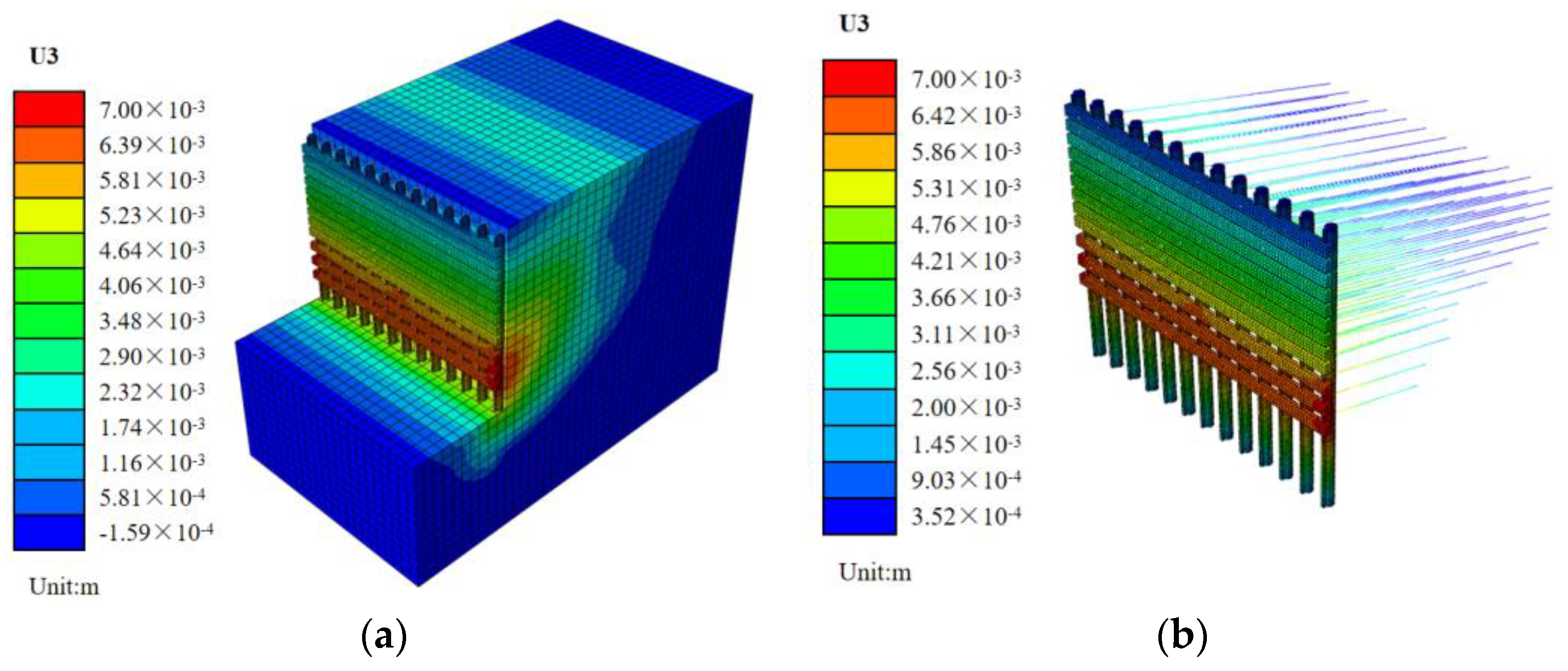
Figure 9a shows the lateral deformation of the whole model, and Figure 9b shows the lateral deformation of the retaining structure. The lateral deformation of the whole model shows the characteristics of sliding mass failure, which is consistent with the deformation characteristics of deep foundation pit excavation. When excavating, the soil behind the retaining structure slides towards the inside of the foundation pit. Thus, the lateral deformation of the lower part of the retaining structure is larger than that of the upper part. The maximum lateral deformation of the retaining structure is close to the bottom of the foundation pit. The lateral deformation of the upper anchor cable is smaller than that of the lower anchor cable, indicating that the lower anchor cable bears more active soil pressure. The lateral deformation of the retaining structure shows that the maximum lateral deformation is 7 mm when excavating to the bottom of the foundation pit, meeting the requirements of construction control standards.
From Figure 10a, the maximum settlement position of the retaining structure is at the pile top when excavating at small depth. With the increase in the excavation depth, the lateral deformation curve of the retaining structure becomes a parabolic curve, and the position of the turning point of the parabolic curve changes constantly. The position of maximum lateral deformation is about 0.9 times the excavation depth from the pile top. The anchorage depth of the pile is the main reason for the difference of the deformation curve when excavating shallow soil and deep soil. When excavating shallow soil, due to the long anchorage depth of the pile, the pile structure is similar to the cantilever structure, so the maximum deformation is located at the pile top. When excavating deep soil, the anchorage depth becomes short, the upper soil pressure is small and the soil pressure near the bottom of the foundation pit is large. Therefore, the soil lateral deformation near the bottom of the foundation pit is large, while that at the pile top is small. When the excavation depth increases, the active soil pressure on the retaining structure also increases. During the initial excavation of the foundation pit, the horizontal displacement of the pile top is the largest, deforming as a cantilever structure, without the anchor cable. The displacement is small due to the shallow excavation depth. When the anchor cable is set, the horizontal displacement of the pile gradually increases and the position of the maximum deformation gradually moves downwards, with the inward convex deformation pattern.
The maximum lateral deformation of the retaining structure by the PARB support system is reduced by 42%, which shows that the support effect of the PARB is better. The maximum lateral deformation of the retaining structure is consistent with the distribution of the maximum surface settlement. The maximum lateral deformation of the retaining structure increases rapidly when excavating shallow soil, but slows down when excavating deep soil.

4.3. Analysis of Pile Top Settlement

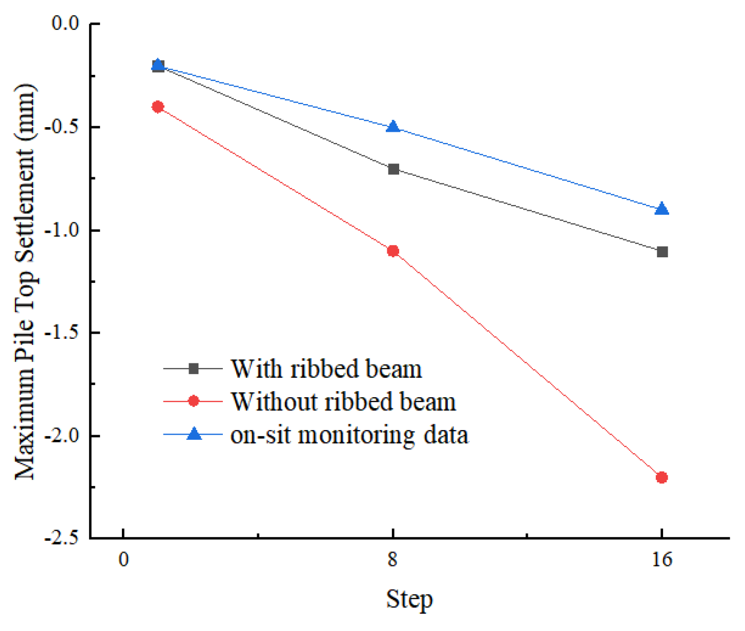
Figure 11 shows the cloud atlas of the retaining structure settlement, and Figure 12 shows the curve of the pile top settlement changing with the excavation step. The vertical deformation of the pile top is too small to be ignored. The anchoring force provided by the anchoring section of the pile and the preload provided by the anchor cable can effectively control the vertical deformation of the pile, which indicates that the embedded depth and the arrangement of the anchor cable in the original design scheme are reasonable.

5. Analysis of Parameters Influence

The factors affecting the control effect of the retaining structure mainly include the stratigraphic parameters and the retaining structure design parameters. This study proposes a new type of support system, so the subsequent content mainly focuses on the influence of the PARB system’s parameters on the support effect, while the influence of other factors on the support effect of the retaining structure has been extensively studied elsewhere [32,33,34]. According to the design parameters of PARB, the influence of the embedded depth of the pile, the size of the ribbed beam and the size of the waist beam on the support effect are investigated separately.

5.1. Pile Embedded Depth

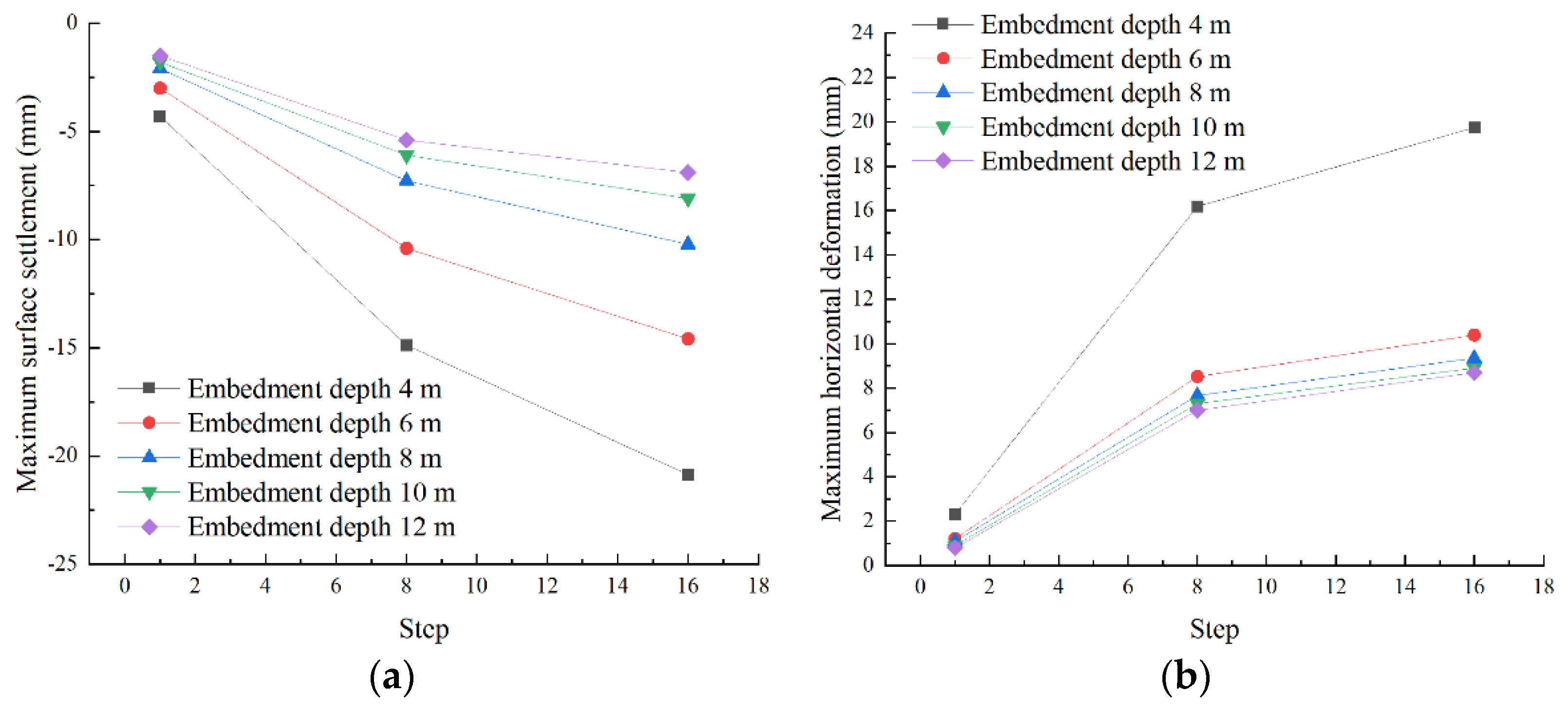
The pile embedded depth in the original design scheme is 6 m. This study set the pile embedded depth as 4 m, 8 m, 10 m and 12 m, when other parameters remained unchanged and compared the maximum surface settlement and the maximum lateral deformation of the retaining structure to analyze the influence of the pile embedded depth on the support effect.
From Figure 13a,b, with the increase in pile embedded depth, the support effect of the retaining structure is stronger. When the embedded depth increased from 4 m to 6 m, the maximum surface settlement and the maximum lateral deformation of the retaining structure decreased by 30% and 48%, respectively. When the embedded depth increased from 6 m to 8 m, the maximum surface settlement and the maximum lateral deformation of the retaining structure decreased by 25% and 10%, respectively. The increase in pile embedded depth has a more obvious control effect on the maximum surface settlement. When the embedded depth exceeds a certain length, the influence on the lateral deformation of the retaining structure reduces.

5.2. Ribbed Beam Size

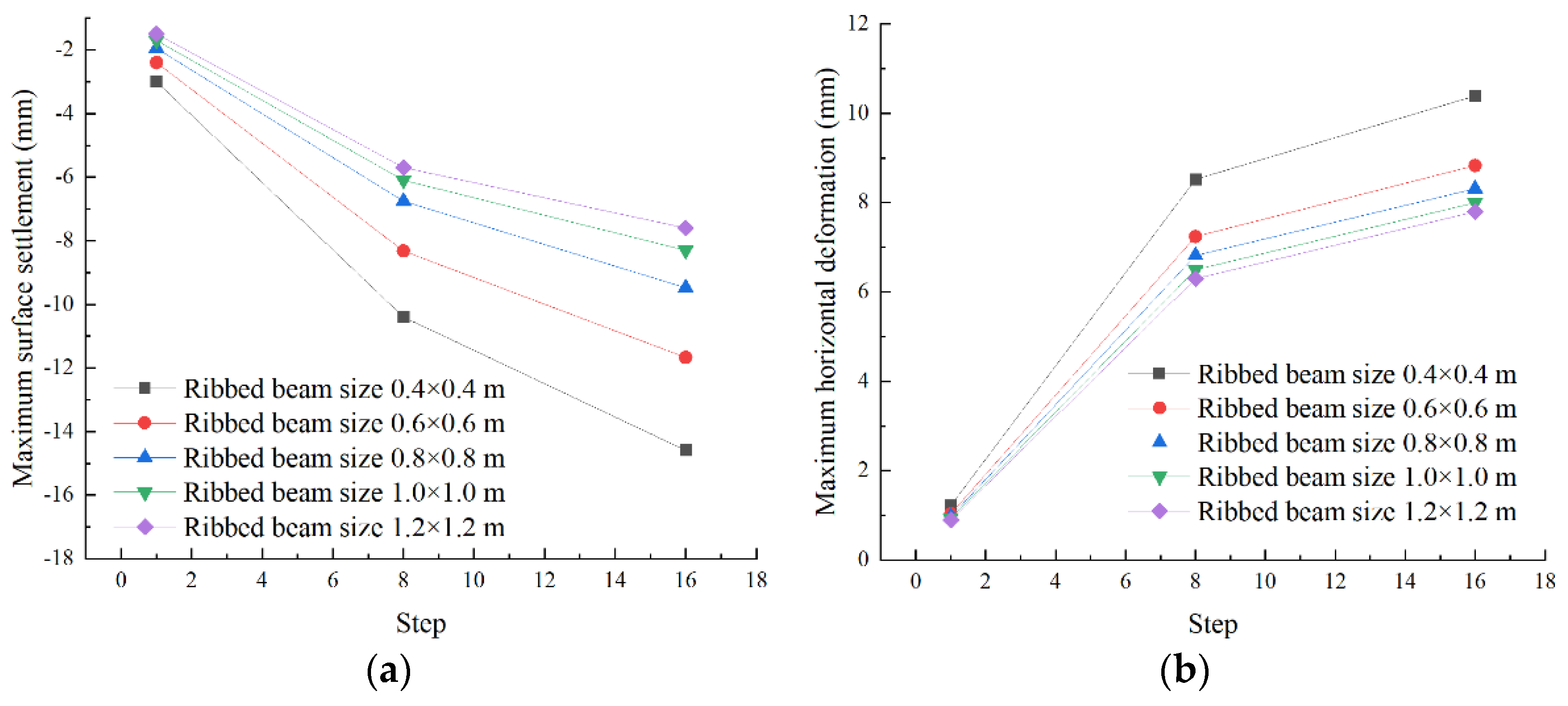
The ribbed beam size in the original design scheme is 0.4 m × 0.4 m. This study set the size of ribbed beam as 0.6 m × 0.6 m, 0.8 m × 0.8 m, 1.0 m × 1.0 m and 1.2 m × 1.2 m when other parameters remained unchanged and compared the maximum surface settlement and the maximum lateral deformation of the retaining structure to analyze the influence of ribbed beam size on the support effect.
Different ribbed beam sizes will change the bending stiffness of the retaining structure, thus affecting the deformation of the retaining structure and the soil loss. From Figure 14a,b, with the increase in ribbed beam size, the maximum surface settlement and the maximum lateral deformation of the retaining structure gradually decrease. When ribbed beam size increased from 0.4 m × 0.4 m to 0.6 m × 0.6 m, the maximum surface settlement and the maximum lateral deformation of the retaining structure reduced by 23% and 14%, respectively. When ribbed beam size increased from 0.6 m × 0.6 m to 0.8 m × 0.8 m, the maximum surface settlement and the maximum lateral deformation of the retaining structure reduced by 19% and 6%, respectively. When the ribbed beam size exceeds a certain range, the influence of the ribbed beam size on the maximum lateral deformation of the retaining structure reduces.

5.3. Waist Beam Size

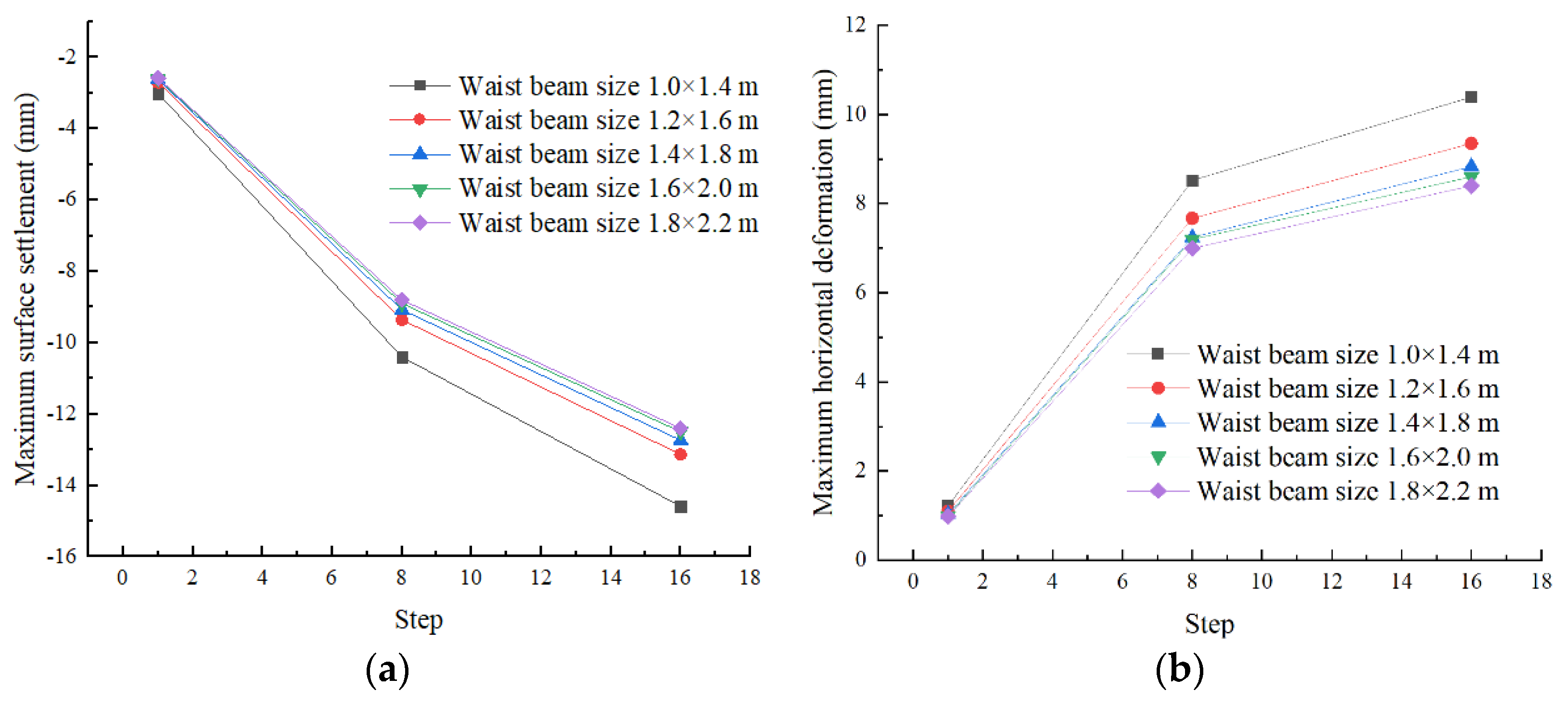
The waist beam size in the original design scheme is 1.0 m × 1.4 m. This study set the waist beam size as 1.2 m × 1.6 m, 1.4 m × 1.8 m, 1.6 m × 2.0 m and 1.8 m × 2.2 m when other parameters remained unchanged and compared the maximum surface settlement and the maximum deformation of the retaining structure to analyze the influence of waist beam size on support effect.
From Figure 15a,b, the change of the waist beam size has limited influence on the maximum surface settlement and the maximum lateral deformation of the retaining structure. When waist beam size increased from 1.0 m × 1.4 m to 1.2 m × 1.6 m, the maximum surface settlement and the maximum lateral deformation of the retaining structure reduced by 13% and 8%, respectively. When waist beam size increased from 1.2 m × 1.6 m to 1.4 m × 1.8 m, the maximum surface settlement and the maximum lateral deformation of the retaining structure reduced by 3% and 6%, respectively. Compared with the influence of embedded depth and ribbed beam size, the change of waist beam size has limited influence on the support effect of the retaining structure. Therefore, if it is necessary to improve the support effect of the retaining structure, it is suggested to increase the pile embedded depth and the ribbed beam size.

6. Conclusions

In this study, the surface settlement and deformation of the retaining structure caused by the excavation of a foundation pit with the PARB support system is studied by the numerical simulation method and compared with the original PAB support system. This study analyzes the difference in support effect by the two support systems, and finally analyzes the influence of embedded depth, ribbed beam size and waist beam size on the support effect of PARB support system. The research results demonstrate the following:
(1) The numerical simulation results are highly consistent with the field monitoring data, which verifies the validity and accuracy of the numerical simulation model. The surface settlement and the deformation of the retaining structure meet the construction control requirements, which proves the applicability of the PARB support system.
(2) Compared with the original PAB support system, when the foundation pit with the PARB support system is excavated to the bottom of the foundation pit, the maximum surface settlement decreases by 33%, and the maximum lateral deformation of the retaining structure decreases by 42%. The vertical deformation of the pile top of the retaining structure is too small to be ignored, because the anchoring force provided by the anchoring section of the pile and the preload provided by the anchor cable can effectively resist the vertical deformation of the pile. Those results show that PARB support system has a stronger support effect.
(3) The PARB support system is consistent with the PAB support system in the surface settlement and the deformation of the retaining structure during excavation, and the curve of surface settlement presents in the shape of a “V”. The position of maximum settlement is about one-half of the excavation depth from the retaining structure. The lateral deformation of the retaining structure is a parabolic curve. The maximum lateral deformation position is about 0.9 times the excavation depth from the top of the retaining structure.
(4) An increase in the pile embedded depth and ribbed beam size can effectively improve the support effect of the retaining structure, while the increase in waist beam size does not significantly improve the support effect. Therefore, if it is necessary to improve the support effect of the retaining structure, it is suggested to increase the pile embedded depth and the ribbed beam size.

Author Contributions

Q.Y.: Conceptualization, methodology, supervision, project administration. H.-L.F.: Methodology, software, data processing, writing, original draft. All authors have read and agreed to the published version of the manuscript.

Funding

This work was supported by Hunan Provincial Education Department Foundation under grant No. 21 C0677, Natural Science Foundation of Hunan province under grant No. 2022 JJ50281 and Research and development project fund number of Hunan Chemical Geological Engineering Survey Institute Co., Ltd.: RD09.

Acknowledgments

The authors thank the Advanced Research Center, Central South University, for providing the experiment conditions. The authors also express special thanks to the editors and anonymous reviewers for their constructive comments.

Conflicts of Interest

The authors declare no conflict of interest.

References

  1. Zhao, X.; Wang, H.; Li, Z.; Dai, G.; Yin, Z.; Cao, S.; Zhou, J. Numerical Study on the Deformation of Tunnels by Excavation of Foundation Pit Adjacent to the Subway. Appl. Sci. 2022, 12, 4752. [Google Scholar] [CrossRef]
  2. Zhang, J.; Qiao, G.; Feng, T.; Zhao, Y.; Zhang, C. Dynamic back analysis of soil deformation during the construction of deep cantilever foundation pits. Sci. Rep. 2022, 12, 1–16. [Google Scholar] [CrossRef]
  3. Yuan, J.; Lin, P.; Mei, G.; Hu, Y. Statistical prediction of deformations of soil nail walls. Comput. Geotech. 2019, 115, 103168. [Google Scholar] [CrossRef]
  4. Johari, A.; Hajivand, A.; Binesh, S. System reliability analysis of soil nail wall using random finite element method. Bull. Eng. Geol. Environ. 2020, 79, 2777–2798. [Google Scholar] [CrossRef]
  5. Danziger, F.; Danziger, B.; Pacheco, M. The simultaneous use of piles and prestressed anchors in foundation design. Eng. Geol. 2006, 87, 163–177. [Google Scholar] [CrossRef]
  6. Zhang, Q.; Hu, J.; Wang, J.; He, P.; Hou, L.; Lin, P.; Song, S. Study on the mechanical behavior of a foundation pit retaining structure adjacent to the pile foundation of a subway station. Environ. Earth Sci. 2021, 80, 1–10. [Google Scholar] [CrossRef]
  7. Zheng, C.; Franza, A.; Jimenez, R. Analysis of floating and end-bearing pile foundations affected by deep-excavations. Comput. Geotech. 2023, 153, 105075. [Google Scholar] [CrossRef]
  8. Liu, W.; Li, T.; Wan, J. Deformation Characteristic of a Supported Deep Excavation System: A Case Study in Red Sandstone Stratum. Appl. Sci. 2021, 12, 129. [Google Scholar] [CrossRef]
  9. Cui, G.; Ma, S.; Liu, Z.; Liu, S.; Xi, C.; Cheng, Z. Effect of freeze–thaw cycles on deformation properties of deep foundation pit supported by pile-anchor in Harbin. Rev. Adv. Mater. Sci. 2022, 61, 756–768. [Google Scholar] [CrossRef]
  10. Su, T.; Zhou, Y.; Wang, Z.; Ye, S. Large Scale Model Test Study of Foundation Pit Supported by Pile Anchors. Appl. Sci. 2022, 12, 9792. [Google Scholar] [CrossRef]
  11. Liu, Y.; Wang, C.; Liu, X.; Gao, R.; Li, B.; Khan, K.U.J. Determination of embedded depth of soldier piles in pile-anchor supporting system in granite residual soil area. Geofluids 2021, 2021, 5518233. [Google Scholar] [CrossRef]
  12. Maleki, J.; Pak, A.; Yousefi, M.; Aghakhani, N. A comprehensive FE study for design of anchored wall systems for deep excavations. Tunn. Undergr. Space Technol. 2022, 122, 104340. [Google Scholar] [CrossRef]
  13. Zhao, W.; Han, J.-Y.; Chen, Y.; Jia, P.-J.; Li, S.-G.; Li, Y.; Zhao, Z. A numerical study on the influence of anchorage failure for a deep excavation retained by anchored pile walls. Adv. Mech. Eng. 2018, 10, 1687814018756775. [Google Scholar] [CrossRef]
  14. Zhang, D.-M.; Xie, X.-C.; Li, Z.-L.; Zhang, J. Simplified analysis method for predicting the influence of deep excavation on existing tunnels. Comput. Geotech. 2020, 121, 103477. [Google Scholar] [CrossRef]
  15. Mitew-Czajewska, M. A study of displacements of structures in the vicinity of deep excavation. Arch. Civ. Mech. Eng. 2019, 19, 547–556. [Google Scholar] [CrossRef]
  16. Jiang, L.; Hao, S. Resilience Evaluation of the Existing Shield Tunnel Lining Induced by the Symmetrical Excavation of Adjacent Foundation Pit Based on Numerical Simulations. Symmetry 2022, 14, 229. [Google Scholar] [CrossRef]
  17. Lei, G.; Guo, P.; Hua, F.; Gong, X.; Luo, L. Observed performance and FEM-based parametric analysis of a top-down deep excavation in soil-rock composite stratum. Geofluids 2021, 2021, 6964940. [Google Scholar] [CrossRef]
  18. Deng, H.; Fu, H.; Shi, Y.; Huang, Z.; Huang, Q. Analysis of Asymmetrical Deformation of Surface and Oblique Pipeline Caused by Shield Tunneling along Curved Section. Symmetry 2021, 13, 2396. [Google Scholar] [CrossRef]
  19. Deng, H.-S.; Fu, H.-L.; Yue, S.; Huang, Z.; Zhao, Y.-Y. Ground loss model for analyzing shield tunneling-induced surface settlement along curve sections. Tunn. Undergr. Space Technol. 2022, 119, 104250. [Google Scholar] [CrossRef]
  20. Ahmed, B.; Voyiadjis, G.; Park, T. Damaged plasticity model for concrete using scalar damage variables with a novel stress decomposition. Int. J. Solids Struct. 2020, 191, 56–75. [Google Scholar] [CrossRef]
  21. Park, T.; Ahmed, B.; Voyiadjis, G. A review of continuum damage and plasticity in concrete: Part I—Theoretical framework. Int. J. Damage Mech. 2022, 31, 901–954. [Google Scholar] [CrossRef]
  22. Gomathi, K.A.; Rajagopal, A.; Reddy, K.; Ramakrishna, B. Plasticity based material model for concrete subjected to dynamic loadings. Int. J. Impact Eng. 2020, 142, 103581. [Google Scholar] [CrossRef]
  23. Yang, Y.; Li, J.; Liu, C.; Ma, J.; Zheng, S.; Chen, W. Influence of deep excavation on adjacent bridge piles considering underlying karst cavern: A case history and numerical investigation. Acta Geotech. 2022, 17, 545–562. [Google Scholar] [CrossRef]
  24. Zhang, D.; Zhang, X.; Tang, H.; Zhao, Z.; Guo, J.; Zhao, H. Effects of soil arching on behavior of composite pile supporting foundation pit. Comput. Part. Mech. 2022, 1–18. [Google Scholar] [CrossRef]
  25. Shakeel, M.; Ng, C. Settlement and load transfer mechanism of a pile group adjacent to a deep excavation in soft clay. Comput. Geotech. 2018, 96, 55–72. [Google Scholar] [CrossRef]
  26. Rashidi, F.; Shahir, H. Numerical investigation of anchored soldier pile wall performance in the presence of surcharge. Int. J. Geotech. Eng. 2019, 13, 162–171. [Google Scholar] [CrossRef]
  27. Ramadan, M.I.; Meguid, M. Behavior of cantilever secant pile wall supporting excavation in sandy soil considering pile-pile interaction. Arab. J. Geosci. 2020, 13, 466. [Google Scholar] [CrossRef]
  28. Baziar, M.; Ghadamgahi, A.; Brennan, A. Numerical analysis of collapse in a deep excavation supported by ground anchors. Proc. Inst. Civ. Eng. Geotech. Eng. 2021, 174, 263–278. [Google Scholar] [CrossRef]
  29. Malhotra, H.; Singh, S. Effect of load inclination on the uplift capacity of the granular anchor pile foundation in cohesive soil. Arab. J. Geosci. 2022, 15, 1088. [Google Scholar] [CrossRef]
  30. Fall, M.; Gao, Z.; Ndiaye, B. Three-dimensional response of double anchored sheet pile walls subjected to excavation and construction sequence. Heliyon 2019, 5, e01348. [Google Scholar] [CrossRef] [Green Version]
  31. Ramadan, M.I.; Ramadan, E.H.; Khashila, M.M. Cantilever contiguous pile wall for supporting excavation in clay. Geotech. Geol. Eng. 2018, 36, 1545–1558. [Google Scholar] [CrossRef]
  32. Do, T.-N.; Ou, C.-Y.; Chen, R.-P. A study of failure mechanisms of deep excavations in soft clay using the finite element method. Comput. Geotech. 2016, 73, 153–163. [Google Scholar] [CrossRef]
  33. Nejjar, K.; Dias, D.; Cuira, F.; Chapron, G.; Lebissonnais, H. Experimental study of the performance of a 32 m deep excavation in the suburbs of Paris. Géotechnique 2021, 1–11. [Google Scholar] [CrossRef]
  34. Nicotera, M.; Russo, G. Monitoring a deep excavation in pyroclastic soil and soft rock. Tunn. Undergr. Space Technol. 2021, 117, 104–130. [Google Scholar] [CrossRef]
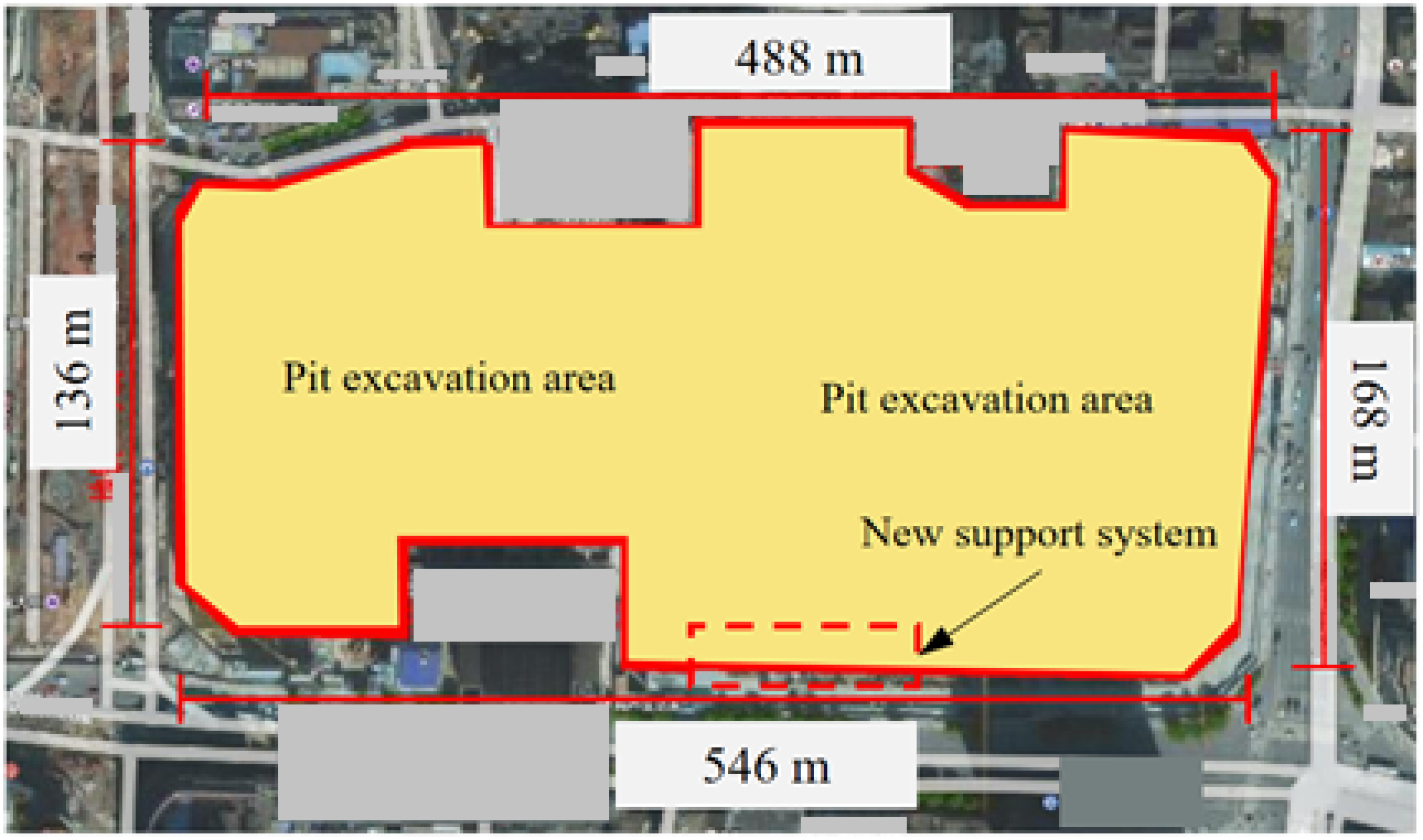
Figure 1. Schematic diagram of foundation pit.
Applsci 13 02379 g001
Figure 2. Reverse construction method of central island. (a) Phase 1 of project, (b) Phase 2 of project.
Applsci 13 02379 g002
Figure 3. Composite support structure of pile, anchor and beam.
Applsci 13 02379 g003
Figure 4. New composite support structure of pile-anchor-ribbed-beam.
Applsci 13 02379 g004
Figure 5. Numerical simulation model. (a) Overall model. (b) Support structure model.
Applsci 13 02379 g005
Figure 6. Concrete tensile–compression stress–strain curve. (a) Tension state, (b) Compression state.
Applsci 13 02379 g006
Figure 7. Cloud atlas of surface settlement.
Applsci 13 02379 g007
Figure 8. Curves of surface settlement. (a) Curve of surface settlement. (b) Change of maximum settlement.
Applsci 13 02379 g008
Figure 9. Cloud atlas of lateral deformation. (a) Whole model., (b) Retaining structure.
Applsci 13 02379 g009
Figure 10. Lateral deformation of retaining structure. (a) Lateral deformation curve., (b) Maximum lateral deformation.
Applsci 13 02379 g010
Figure 11. Cloud atlas of retaining structure settlement.
Applsci 13 02379 g011
Figure 12. Settlement curve of pile top.
Applsci 13 02379 g012
Figure 13. Different embedded depth. (a) Maximum surface settlement. (b) Maximum lateral deformation.
Applsci 13 02379 g013
Figure 14. Different ribbed beam size. (a) Maximum surface settlement. (b) Maximum lateral deformation.
Applsci 13 02379 g014
Figure 15. Different waist beam size. (a) Maximum surface settlement. (b) Maximum lateral deformation.
Applsci 13 02379 g015
Table 1. Details of anchor cables.
Serial NumberAngle (°)Length (m)Preload Force (kN)Diameter (m)Anchor Point Depth (m)
1855.54500.15−3.0
2863.54500.15−5.0
38564500.172−7.0
48224500.15−9.0
51529.56500.172−11.0
615266500.172−13.0
715236500.172−15.0
815226500.15−17.0
915206500.15−20.0
1015206500.15−23.0
1115206500.15−26.0
1215206500.15−29.0
Table 2. Stratum material parameters.
Natural Gravity
γ (KN/m3)
Cohesion
c (kPa)
Friction Angle φ (°)Elastic Modulus
(MPa)
Poisson’s Ratio
Plain fill19.512880.3
Mucky soil18.212640.35
Silty clay19.53018160.25
Coarse sand20.2035400.25
Round gravel20.5040600.25
Strongly weathered argillaceous siltstone21.94040820.25
Moderately weathered argillaceous siltstone22.948484600.25
Table 3. Parameters of retaining structure.
MaterialElastic Modulus (MPa)Natural Heavy γ (KN/m3)Poisson’s RatioSize (m)
Waist beamConcrete3523.50.281.0 × 1.4
Ribbed beamConcrete3523.50.280.4 × 0.4
Crown beamConcrete3523.50.281.0 × 1.4
Cast-in-place pileConcrete3523.50.28Diameter 1.4
Anchor cableCable200 × 103-0.20Diameter 0.15 or 0.172
Disclaimer/Publisher’s Note: The statements, opinions and data contained in all publications are solely those of the individual author(s) and contributor(s) and not of MDPI and/or the editor(s). MDPI and/or the editor(s) disclaim responsibility for any injury to people or property resulting from any ideas, methods, instructions or products referred to in the content.