1. Introduction
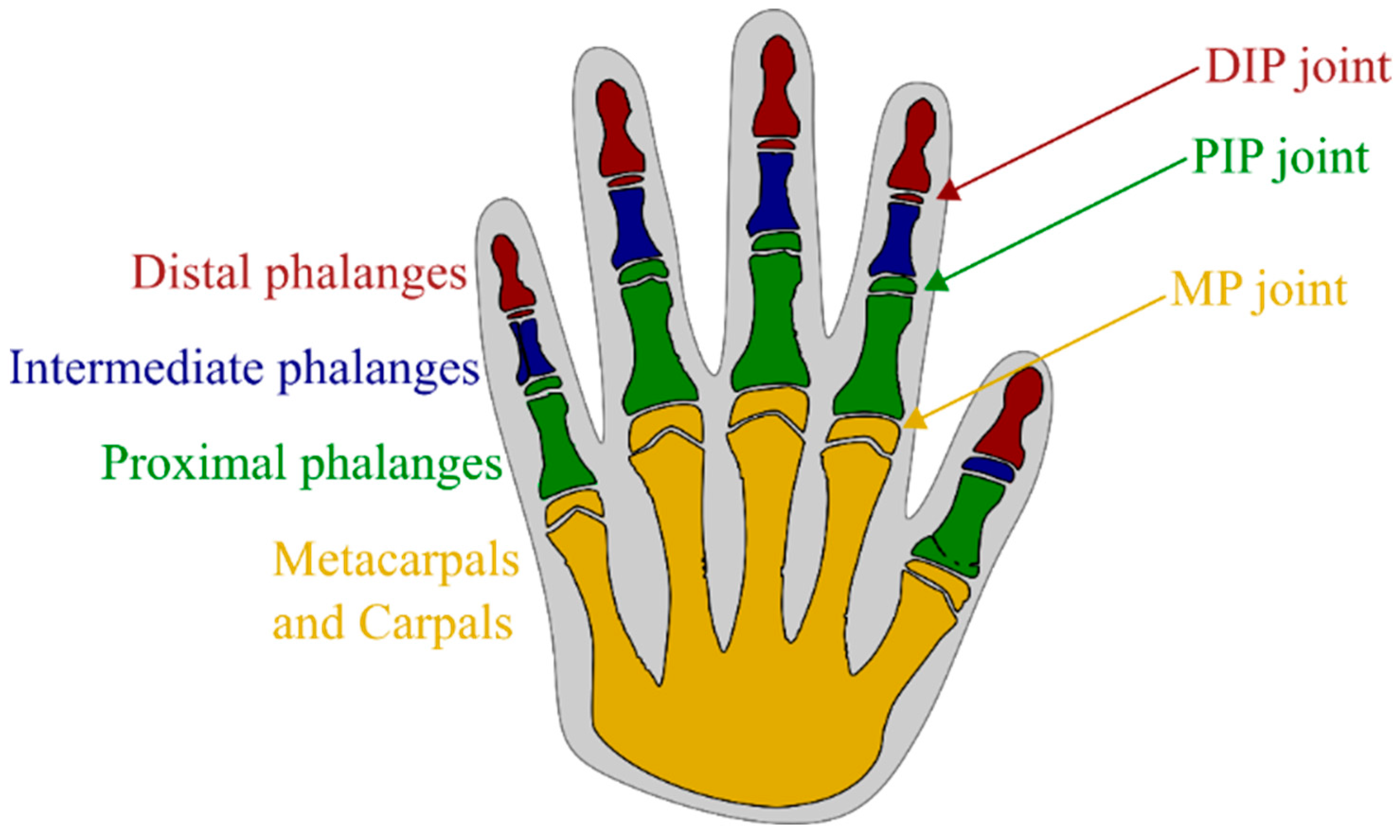
Mechanisms produced by conventional methods do not fully resemble what nature can create. Classic hinge mechanisms are an example of this, but nevertheless, they are used in all areas of engineering due to their simplicity of operation, robustness, understanding of the operation principles, and quick and easy designing. In order to be able to create a more realistic model of the human hand, one should turn to some unconventional types of mechanisms. This can be achieved with the use of ever-increasing compliant mechanisms. In this paper, this type of mechanism is used to simulate the movement of the human hand. Such simulation can be used for many purposes, one of which is in the development of 3D model of a human hand that could be used in various applications, such as hand rehabilitation.
In order to make a hand-compliant mechanism as realistic as possible, in this paper, Finite Element Analysis (FEA) of the designed model of a human finger was first applied, followed by an experiment with the use of a digital protractor and a camera to test the position accuracy within the motion range in real conditions.
To date, published papers addressing the building of human hand mechanisms have different approaches. Observing only those that utilize the material flexibility for movement, one can classify them into two groups: those that have finger or finger-pad compliance group and those that have joint compliance. The first group uses the soft robotic approach, and the papers [
1,
2,
3,
4,
5] show the state of the art, development, and future progress of this group. A soft touch approach is applied in this case, where the entire length of flexible elements is used for different applications. Applications of such soft gripping devices are different, such as actuators, sensors, medical tools, and rehabilitation devices. Grippers are perhaps the most abundant in this area. The study in paper [
6] presents a robotic end-effector that perfectly replicates the actions of the human hand in terms of gripping and manipulating items. The soft robotic gripper shown in the paper [
7] consists of three soft finger bends and one passively adaptive palm. In practice, the soft gripper could achieve a gripping force of 40 N at low actuation pressure below 100 kPa and, thus, can pick up objects of all sizes with a convex shape. Similarly, paper [
8] shows a three-breasted gripper with a matched spine of each finger made of 3D-printed polylactic acid (PLA) materials sandwiched between thin-layer materials. Here, one can cite works [
9] and [
10], where the modeled grippers do not take the shell of the hand as a model but are free-form structures obtained by topological optimization.
A diverse series of alternative uses of structural compliance to develop simple, adaptive, compliant, and/or underactuated robotic graspers and arms that can efficiently and robustly perform various grasping and dexterous hand manipulation tasks are presented in [
11].
The same study demonstrates the application based on the joints’ flexibility. They represent the second group of flexible structures that use the methodology of compliant mechanisms. For the most part, these were inspired by endoskeletons used for grasping applications, and due to their external appearance, they resemble human fingers [
12]. In papers [
13,
14,
15], mechanisms developed in this way for the needs of the end-effector of the robotic arm are presented. The paper [
16] that uses elastic ligaments and antagonistic tendons to construct anthropomorphic joints with multidirectional passive compliance as a substitute for human finger joints can be mentioned here.
Papers [
17,
18,
19] show a combination of both groups, finger compliances and joint compliances, which is a new approach to soft grippers. Cited paper [
18] deserves special attention. In this paper, a pressure sensor is placed on the fingertip of the elastic structure to form a soft robotic functional system. This single-build process with the advantages of multiple bodies, silicone rubber, and highly stretchable hydrogel is a popular choice for 3D printing of soft materials, which is an advantage of this approach.
Papers [
20,
21,
22] show some of the ideas of how the flexibility of elements can be used in terms of hand rehabilitation. It can be said that they represent exoskeletons or endoskeletons that can be used to help people lift heavy loads and help with movement in case of immobility.
In this paper, an extension of the research that we presented in the paper [
23] concerning the 3D-printed soft touch robotic manipulator is presented. In paper [
23], the compliant gripper was developed as a controlled robotic manipulator to achieve smooth gripping of delicate objects where computer vision was used to collect feedback from which intelligent algorithms can control motion and grasping, and in this way, enable the gripper’s ability to manipulate objects with extreme precision. The compliant gripper was created as a test to demonstrate that the presented building method enables adaptive soft touch grasping capabilities. Hence, only a limited range of gripper fingers bending angles was examined, and the gripper’s design was only cursorily developed. For the purposes of extension to different applications, such as the field of hand rehabilitation, the griping compliant mechanism can be adapted to the idea of the human hand as an apparatus for some subsequent use. This adaptation is the core of the work presented in this paper in the following sections. In contrast to the paper [
23], simulation, analysis, and experimentation in the range of large deformations of two compliant mechanisms obtained by the synthesis of compliant mechanisms (fabricating compliant copies of classical mechanisms, i.e., the mechanism of the human finger) were performed.
On the basis of the reviewed literature and the ever-increasing use of compliant mechanisms, this paper addresses the designed model of the human finger compliant mechanism. The paper aims to analyze the position accuracy within the motion range of this compliant finger model via FEA as well as to compare results with real-life experiments. Hence, an experimental setup with a digital camera and integrated computer vision system, which examines the position accuracy within the motion range of the loaded 3D-printed compliant finger prototypes, is presented. The paper is organized into seven sections, where in addition to the introduction given in
Section 1, the design methodology with a description of the human hand, flexure hinges, and their types, and the final model of the compliant finger are described in
Section 2. FEA and experiment setup are presented in
Section 3 and
Section 4, respectively. The image processing method is presented in
Section 5, and the results are in
Section 6. The conclusion, overview of the results, and further research directions are given in
Section 7.
3. Finite Element Method
The Finite Element Method (FEM) was used as the basic tool for the analysis of compliant fingers [
12,
18]. Through the numerical solution of mathematical equations, an iterative process simulates the investigated type of mechanisms, otherwise known as Finite Element Analysis (FEA). The ANSYS software package uses this approach for the detailed analysis of the structures under investigation and was used for the analysis in this paper. Simulation and analysis were performed in ANSYS version 19.2 [
29]; for them to produce valid results that can be compared with the obtained experimental results, it is necessary to fully define the given compliant mechanism. Given that compliant mechanisms dimensions are already provided as an input parameter, it is now necessary to define the material from which the compliant mechanism is constructed. For these purposes, Fused Deposition Modeling (FDM) 3D printing of Nylon material was used to create prototypes of compliant fingers. The specifications of Taulman Nylon 230 obtained from the manufacturer can be seen in
Table 1 [
30], and the 3D-printing process itself is described in the following.
Taulman Nylon 230 is a perfect option given its flexibility-to-strength ratio. With this nylon used in 3D printing, there is no snapping or brittle effect, and the parts produced are very tough, durable, and resilient. In contrast to that, the thinner sections of the 3D-printed nylon can become highly flexible. Hence, Taulman Nylon 230 is perfect for the production of compliant mechanisms prototypes and the end-use flexure components. The next step is the detailed definition of the static and dynamic characteristics given by the real conditions under which the experiment will be performed.
Figure 6 shows the defined boundary condition (fixed support A) and the load force (vector B defined in the negative direction of the horizontal axis) acting on the end of both compliant mechanisms with a 21-degree bend curved flexure hinge (
Figure 6a) and a 90-degree bend curved flexure hinge (
Figure 6b).
It is also necessary to generate a finite element mesh and its goodness is an important factor for a successful analysis. At the locations of the flexure hinges, a mesh of finite elements is produced using the “Face Meshing” function to meet the correctness of the FEA results. A complete mesh is defined with quadrilateral components of size of 0.8 mm for rigid segments of compliant mechanisms and 0.2 mm for elastic segments (flexure hinge). For a compliant mechanism with a curved flexure hinge with a 21-degree bend, the resulting mesh of the FE model contained 2298 elements and 7307 nodes, while for a compliant mechanism with a 90-degree bend, it contained 2343 elements and 7478 nodes. Non-linear FEM analysis is considered in the simulation since the static analysis takes large deflection into account. Simulation parameters maximal bending angle, and maximal strain are output parameters of interest, the results of which, in the case of maximum load force, can be seen in
Figure 6.
4. Experimental Setup
For the purposes of the evaluation of the FEA results of bending angle range, measurements were performed under controlled conditions adapted to the experiment, as shown in
Figure 7. For determining the bending angle of the 3D-printed finger joint, a computer vision system with Hikvision Darkfighter DS-2CD7026G0 Network IP camera was chosen. The camera was previously calibrated for the given measurement setup.
Figure 7 explains the experimental setup in detail, where a 3D-printed finger (1) is attached to the supporting structure (3) in the MP joint at one end, while the other end remains free. At the top of the finger, there is an opening where a thin nonelastic string (5) is pulled through and a load is connected to a string’s free end (4) so that the load is perpendicular to the supporting structure. This way, the experimental setup mimics the FEA simulation. The camera (2) is placed sideways so that it captures optimal frontal projection.
For designing the technological process of 3D printing with the purpose of experimental prototypes of the compliant fingers, it is necessary to choose adequate printing parameters. The prototypes of the finger were 3D-printed on Creality Ender 5 PRO using FDM, which is a frequently applied additive manufacturing technology.
The process of creating 3D objects using filament, Taulman Nylon 230 in this case, is performed by heating the 0.4 mm diameter nozzle of the 3D printer to 235 °C, which results in the filament changing to a semi-liquid state. Layer height is 0.15 mm and is applied in each iteration, and layer by layer of material is joined with previously applied layers. All the printing parameters are listed in
Table 2.
Once the prototypes were printed and the experiment setup was installed, the measurements of the motion range were taken. By recording the image of the 3D-printed prototype in different positions, it was possible to determine the path and angle of the prototype’s end that occur when the load was added in the mentioned way. Processing of the recorded images was performed using a program written in Python, using the OpenCV library of algorithms.
Weights of 10 g, 20 g, 30 g, and 40 g were added one after the other in order to determine the maximal 3D-printed compliant finger bending angle (as described in the previous section). Images were taken for each position of the measurement series when the system was in balance, and after that, the angles were measured using computer vision. The system remained unloaded between each measurement until it returned to its original position.
The results of measurements after image processing were compared with manual measurements using a digital protractor, and they are presented and discussed in the
Section 6.
5. Image Processing
For the experiment, computer vision was used to approximate the bending angle of the finger joint. The use of image processing for this type of experiment setup ensures an accurate approach to collecting measurements, which means that, apart from the calculation error, the measurement error is reduced to the initial marking of the object and the appropriate placement of the camera (both calibrations are addressed in the first instance of the experiment). The advantage of setting up an experiment with a high color contrast in the imaged scene lies in the fact that black and white image regions have a distinct difference in pixel values between the object and the background, which helps in detecting the desired object region. In the presented experiment, 3D-printed finger of black color is placed on the white background. The image processing task is divided into two parts: recognizing the segment of the joint of the 3D-printed finger that bears the load and determining the bending angle when the joint is loaded.
The camera records the video from which the necessary images are extracted (in the initial position of the 3D-printed finger and under the mentioned loaded case) for real-time object detection. One of the most effective object detection techniques that serve as a point of reference for object detection in computer vision projects is the bounding-box-based object detection. Bounding-box detections are represented by outlining the rectangles, which fully bound the objects in the image, with the x- and y-image coordinates of the rectangles’ centers, as well as with the width, and height of the rectangles. After that, the bending angle about the y-axis (vertical axis of the image coordinate system) is calculated. As was said in
Section 4, image processing is performed using a program written in Python, using the OpenCV library of algorithms with the function cv2.MinAreaRect(). The cv2.MinAreaRect() function employs the rotating calipers approach to identify the minimal rectangle that encompasses the object region in the image. First, the original image (
Figure 8 left) is segmented using thresholding-based segmentation. The rectangle extraction procedure begins by determining the convex hull of the set of points on the boundary of segmented object region and subsequently rotating a line segment, known as “calipers” around the convex hull while measuring the dimensions of the rectangle created by the calipers and convex hull during each rotation. The rectangle with the least area is selected as the minimum area rectangle.
Figure 8 shows an example of extracting an object using the function cv2.minAreaRect() [
31], which extracts a rectangle (bounding box) of the smallest area around the desired shape. The lower portion of the compliant finger that is being imaged is covered to guarantee that just the rectangle that is of interest for the presented analysis, i.e., the rectangle with the smallest area, will be extracted.
Figure 9 shows an example of a loaded finger joint using the developed function for measuring the bending angle about the y-axis (vertical axis of the image coordinate system). A segment of interest is isolated by markers of contrasting color value because the algorithm separates pixels of low and high color properties (hue, color saturation, and value) and then identifies the largest morphologically closed contour inside the processed image.
The value shown in
Figure 9a is the initial position, while
Figure 9b represents the difference between the found bending angle and the image coordinate system y-axis.
6. Results and Discussion
Table 3 shows the results obtained by experimental measurement of the bending angle of the 3D-printed finger using computer vision, manual measurement with an electronic protractor, and numerical results obtained by FEA.
As can be noticed, FEA results show a large error with respect to experimentally measured values in cases where small loads were applied, while in cases of maximum loading, this error is reduced. FEA shows that both compliant fingers have very similar results in output angles but still provide better results for a curved flexure hinge with a 90-degree bend. On the other hand, the experiment shows that a 21-degree bend curved flexure hinge provides better results. The reason for that can be contained in the assumption that the information provided by the material manufacturer is different for the filament used for 3D-printed prototypes of fingers.
In order to prove this assumption, a tensile test was performed to determine the material properties of 3D-printed test specimens (
Figure 10). The tensile test was performed according to the international standard ISO 527-2, which determines the tensile properties of molding and extrusion plastics. In
Figure 10a, the test specimen at the beginning of the tensile test (without a load) can be seen, and in
Figure 10b, the test specimen during the load stage is shown.
As a result of the tensile test for the 3D-printed Taulman Nylon 230 material, the stress–strain curve shown in
Figure 11 was obtained. The orange line illustrates the hypothetical straight line that the material would follow if it were constantly in the area of elasticity (in the region where Hook’s law applies), whereas the blue line depicts the actual behavior of this material when it is stretched. The slope of the straight-line portion of the stress–strain curve can be utilized to define the modulus of elasticity (Young’s modulus). Special attention should be paid to the instant of the stress point where the material enters the non-linear deformation region (i.e., when the blue and the orange lines diverge), as this is the region where the compliant fingers material is when the large angular deformations take place.
All the values of the mechanical parameters required for the simulation and FEA are determined by examining the data collected from the performed tensile test. The entire set of mechanical parameters for the 3D-printed Taulman Nylon 230 material is presented in
Table 4. As can be observed, the acquired Young’s modulus is nearly 4.5 times greater than the manufacturer’s Young’s modulus (manufacturer’s Young’s modulus—73 MPa; Young’s modulus obtained by tensile test—325 MPa), while ultimate tensile strength is not that different.
With the experimentally acquired mechanical characteristics, FEA of the compliant fingers was carried out. The FEA setup was the same as that described in
Section 3, with a few additional improvements. A mesh is now defined as a size of 0.2 mm for rigid segments of compliant mechanisms and 0.05 mm for elastic segments (flexure hinge). This was implemented in order to ensure the repeatability of the FEA results, which has a stress convergence test tolerance below 1%. A compliant mechanism with a curved flexure hinge with a 21-degree bend now has the resulting mesh of the FE model, which contains 32,615 elements and 33,425 nodes, while a compliant mechanism with a 90-degree bend contained 34,552 elements and 34,552 nodes. The force with which the compliant fingers were loaded in the simulation corresponds to the product of the mass of the weights (from the initial 10 g to 60 g) with which the experiments were performed and the gravitational acceleration obtained at the site where the experiment was performed (the value of the gravitational acceleration for the city of Niš, Serbia, is 9.80408 m/s
2). Adding forces corresponding to weights of 50 and 60 g was necessary so that in FEA, we could obtain results of maximum bending angles that correspond to the theoretical range of motion for the PIP joint of 100 degrees. The resulting forces and deflection angles obtained by FEA can be seen in
Figure 12. The difference between bending angles for the two types of compliant fingers can be clearly seen. Better angle results are produced by a compliant finger with a 90-degree bend curved flexure hinge (red line), which is visible even at modest load levels.
The above results should be seen as results in terms of internal stress and strain. In
Figure 13, it can be seen that the compliant finger with a 90-degree bend curved flexure hinge has minor stress through the entire range of angular deformations. The maximal stress in the end position at the highest load force for a 90-degree bend curved flexure hinge is 17.324 MPa for bending angle
θ = 102.721°, and for a 21-degree bend curved flexure hinge, it is 17.406 MPa for bending angle
θ = 93.789°.
As a result of all the above, it was necessary to repeat the experimental measurement in order to provide the values of the angles for the weights of 50 and 60 g so that we could perform a comparison with the FEA. Therefore, two new prototypes of compliant fingers were 3D-printed, which served us for the desired experimentation. This opportunity was used to repeat the already conducted experiment once more, ensuring the outcome results of the earlier experiment (
Figure 14).
Table 5 shows the newly obtained results of the experiment (Computer Vision Method) and FEA. The results presented in this way clearly confirm the similarity between FEA and experimental results in the area up to 70 degrees for curved flexure hinge with a 21-degree bend and up to 80 degrees for curved flexure hinge with a 90-degree bend. In the area larger than the above-mentioned angles, the results diverge. This outcome can be attributed to the behavior of the material, which in the area of large deformations tends to creep after the addition of weights heavier than 40 g. With the graphic in
Figure 13, this can be confirmed because, in these areas, the stress is greater than 12 MPa for both compliant fingers. This also refers to
Figure 11, where, as already noted, the material enters the non-linear deformation region.
The difference between the previously performed experiment (
Table 3) and the newly performed experiment (
Table 5) should also be explained. The conclusion of the difference in results is explained by the fact that the previous experiment was performed after the bending test of 3D-printed compliant finger prototypes. This means that the prototypes were previously brought to a state of large deformations, whereby plastic deformation remained in the material. It should be noted that these permanent deformations were not seen and that the prototypes had the ability to return to their initial state, but the experiment performed with such plastic deformations in the material cannot be considered valid.
7. Conclusions
In this paper, a model of a compliant mechanism that is a counterpart to the human hand was discussed. For this purpose, compliant mechanisms are the perfect choice due to their properties and benefits compared with traditional mechanisms, such as no need for lubrication, no noise or oscillations, and wear caused by clearance in the joints. Therefore, two types of compliant fingers were analyzed. Prototypes with curved flexure hinges of mentioned fingers were 3D-printed in order to experimentally prove which of these two types represents a more adequate solution. Such models can be used in various applications, such as robotic grasping devices that simulate the movements of a human hand, interactive video gaming, and hand rehabilitation [
32]. In the case of hand rehabilitation, the discussed models could be used as parts of the hand exoskeletons for patients with impaired hand fingers’ movements or parts of the “movement training by imitation” rehabilitation systems, where the patient would be asked to imitate the movement of the fingers’ models tele-operated by the therapist or intelligently controlled to demonstrate particular movements of the figures and hand gestures.
Presented simulations and parametric analyzes were performed to demonstrate the accuracy of the software analysis to correspond with the experimental results and, thus, to use this method for further research. The initially obtained results showed a poor correlation between experimental and FEA results. The assumption was made that the information provided by the material manufacturer was different from the filament used for 3D-printed prototypes of compliant fingers. This is a common mistake when experimenting with 3D-printed prototypes.
As a solution, adequate measurements should be taken to obtain the correct specifications for 3D-printed compliant fingers and set the correct parameters for the FEA simulation. To demonstrate this possible solution, tensile test was performed to determine the material properties of the 3D-printed test specimens, which were used for the re-executed FEA.
The newly obtained results showed a good correlation between experimental and FEA results. In the areas of low and medium deformations, the agreement of FEA and experimental results could be seen within the limits of less than 10%. The limit increases to 25% in regions with high deformations. This discrepancy can be attributed to the fact that the printed elements are often not of homogeneous structure, while the model obtained by simulation is completely idealized. It should also be emphasized that the program in which the analysis was performed does not provide optimal results related to the non-linear area of deformations.
The next step would be to implement such a method for the case of a compliant finger that would have all the necessary joints that would allow the realistic range of motion that human fingers have. The analysis of such a compliant finger would complete the entire development of the hand-compliant mechanism, which could later be used in various applications, such as the hand rehabilitation device mentioned above, with the help of adequate control for its actuation.


 ,
, 


