Communication

Aspects Related to the Design and Manufacturing of an Original and Innovative Marker Support System for Use in Clinical Optometry

Department of Mechatronics and Precision Mechanics, Faculty of Mechanical Engineering and Mechatronics, University Politehnica of Bucharest, 060042 Bucharest, Romania
*
Author to whom correspondence should be addressed.
Appl. Sci. 2023, 13(5), 2859; https://doi.org/10.3390/app13052859
Submission received: 10 January 2023 / Revised: 17 February 2023 / Accepted: 21 February 2023 / Published: 23 February 2023
(This article belongs to the Special Issue Mechatronics System Design in Medical Engineering)

Abstract

:
The compliant mechanism studied in this paper is used in the structure of an assembly necessary for the temporary mounting of visual markers on glasses frames. Proper correction of vision defects in patients is a field of study in healthcare that has grown in complexity, along with all aspects of technology, over the past decades. As such, along with better lenses and frames, including custom solutions, the devices used to determine the patient’s specific parameters need to be more complex and precise. However, this is only part of the problem: while many devices exist that take measurements such as interpupillary distance with great precision, these come at a very high cost and do not take into account aspects related to real-life usage of the lenses, such as the patient’s position, angle, etc. Given the considerations above, this paper approaches the design, simulation, realization and testing of a working model of a frame used to support markers used in the optometry process. The design proposed in this paper assumes that the system used can be used while the glasses are mounted on the patient’s face, without influencing in any way their position in front of the patient’s eyes. Furthermore, the system must allow assembly and disassembly with minimal effort, to allow the patient to perform some movements without changing the position of the frame, as well as the easy access to the markers mounted on the spectacle frame. The main scope of the paper is to design and choose the correct constructive solution of a compliant mechanism for this important clinical optometric application in terms of geometric parameters, material and technology used to obtain appropriate performances. The authors highlight how the parameters and manufacturing technology for the device were chosen, and a finite element analysis is used to simulate the mechanical behaviour of the mechanism and to choose the optimal variant in terms of the desired displacement between three proposed materials for the given application. After justifying the choice of the constructive solution, several physical models of optometric support markers were realised using Fused Deposition Modeling (FDM), and Polyethylene terephthalate glycol (PETG) or polylactic acid as materials. Furthermore, an electro-pneumatic experimental test stand was developed to simulate and test the functionality of the device and to validate the proposed model.

1. Introduction

The use of multiple types of measuring systems is widespread in the field of optometry, and specialists rely on such devices along with specific methods to determine a patient’s specific needs in regard to customizing lenses. In this regard, certain aspects of measuring these parameters are perceived as being mandatory, such as determining the user’s perceived effect of the lenses on vision in a real-world environment: reading a computer screen, a book, looking in the distance. One such aspect is that the glasses and lenses should be mounted on the patient’s face, and their position should not be in any way modified by the measuring apparatus. This is especially true when it comes to personalised progressive lenses. As such, certain requirements have been identified, as explained below:
-
High elasticity—the mount should allow for usage with a wide array of models of glasses.
-
Maximum weight 5 g—total weight of the system will be two such mechanisms, for a total of 10 g. It was considered that the mounting bracket should not be heavier than one of the lightest pairs of glasses. This is mostly an empirical parameter, based on previous iterations of such systems.
-
Good resistance to repeated usage—the system should not be prone to easily breaking while being used for multiple dimensions of seeing glasses.
-
Easy to manufacture, but especially easy to modify between product iterations due to the shifting fashions in eyewear; the mounting bracket should easily follow suit.
-
Low cost and good aesthetics
-
Made in one part—measuring accuracy will greatly depend on how well the system is assembled. Related to this last point, a special model of a compliant mechanism that achieves the transmission of force and motion through its own elastic body transformation was proposed. Through several iterations, a shape was obtained, mostly being designed around the normal shape of a user’s glasses frames.
Figure 1 shows two views of the proposed mechanism (side and isometric view), which is equipped with two handles.
A force of approximately 35 N (each) will be exerted on them, which is necessary to open the mechanism with a total stroke of 30 mm. The forces necessary to open the mechanism are determined following the study in the specialized literature [1], and of some simple tests performed in the laboratory—allowing an average user to open the device with minimal effort.
Similar systems have been developed for use in the field of optometry. Such systems, currently employed throughout optometry clinics allow for easy measurement, with relatively low errors of a small number of parameters, such as interpupillary distance, total, left and right, as well as a basic calculation of the boxing parameters needed when cutting and fitting the lens to a specific frame. One such example is the VisionFit Dispensing System [2], which allows for measurement of interpupillary distances both for near and far, boxing measurements, as well as some fitting parameters of the frames. This system does not, however, allow for complex measurements to be taken (curvature of frames and pantoscopic angle). Another such system is the Optikam [3], which allows measurement of a much larger number of parameters, but does feature a very large and complex system for attaching the markers to the patient’s face, and thus runs the risk of interfering with the natural position the frame would otherwise have on the patient’s face. Another such system is the DigiFit, which allows for measurements of a large number of parameters, but does, however, generally require the lens to be taken out of the frame. Since some corrections, such as squinting, are made by the lens, a complex system must be employed to allow for corrections to the lens’s optic centre [4].
While the systems presented thus far allow for some parameters to be measured, there are systems under use that allow for all parameters to be obtained. These, however, are very expensive and usually require special training and occupy a large part of the clinic for use. One such system is the highly capable ZEISS i.Terminal 2 [5].
An important aspect in choosing the technology used is also the ease with which the mechanism can be manufactured, without the need for specialized training and in proximity to the field of operation (optometry). It is also important to consider the biocompatibility of the materials used, as this mechanism will be used in the immediate vicinity of patients, it is desirable that it does not affect their health in any way. One last important aspect is the possibility of recycling these devices. Choosing a metal or composite material will make it difficult to recycle the material to produce other devices [6].
Starting from the conditions listed above, several more variants of materials and manufacturing technologies have been considered. These include:
-
Plastic injection—the first of the technologies considered has the disadvantage of the very high initial cost (mould cost), as well as the difficulties encountered in case of modification to the initial model [7,8,9,10]
This technological process can only be considered if it is desired to produce a very large number of components, without changing their shape [7,8,9,10].
-
Selective laser sintering—this technology allows rapid modification of the model used, is compatible with elastic materials, but the prohibitive costs and special conditions of use make it unsuitable for the requested model [11,12,13,14].
-
Stereolithography—this technology has several advantages, such as the relatively low price of the equipment and ease of use, while disadvantages include the high cost of the polymer and the fact that it requires ventilation installation [15,16,17,18].
-
Thermoplastic extrusion—FDM technology allows the realization of prototypes in a very short time, from a very wide range of materials that have a low price and are affordable [19,20,21,22].
The wide spread of this technology has allowed for the very rapid development of both commercial solutions for depositing plastic in layers and materials. FDM technology involves the deposition of a continuous flow of material in the form of a heated filament to obtain geometric shapes, under the control of a computer system. Deposition usually occurs on the x and y axes (plane) with the increment of the Z axis after complete deposition of the material on the current layer. The thermoplastic materials used are part of an extraordinarily wide range and include Polylactic acid PLA, Acrylonitrile Butadiene Styrene ABS, Thermoplastic Polyurethane TPU, Nylon, Polyethylene terephthalate glycol PETG, and other variations of them or composite materials.
Among the presented solutions, the FDM technology corresponds in terms of cost and quality for the execution of the compliant mechanism [23].
The materials used to make the mechanism were chosen based on the mechanical characteristics, availability, and cost price: PLA, ABS and TPU. The shape of the mechanism was determined after multiple experiments over several iterations and using the pros and cons of current marked solutions. Regarding the size and stroke of the mechanism, they were determined by measuring the lowest and highest frame sizes usually encountered in the industry. Furthermore, a key determining factor of the size was the industry standards in terms of lens size before it is cut to fit the frames (between 60–70 mm). Along with this, the shape allows for easy dimensioning up or down, with regards to using FDM technology.
The shape and usability cases for the device were based on tens of years of experience in the field of optometry. For the shape and requirements for the system, feedback received from users who have employed similar systems for a number of years was considered. Since the device will come into contact directly with both the optometrist and the patients, it was very important that their feedback be the starting point for the design, and also, that ease of use was a significant factor in determining the final shape of the frame. There are no similar devices on the market in terms of the shape of the device, method of use, or technologies used to produce it. Table 1 presents several constructive solutions proposed by the authors with the characteristics described.

2. Finite Element Analysis of Proposed Shape

In order to predict the displacement of the proposed system and, in this sense, to choose the optimal material to realize the physical model for the given application, the designed structures were simulated using the finite element method, starting with three materials frequently used in FDM technology.
With the help of finite element method analysis, the 3D model was simulated assuming that it was divided into several smaller elements, with their size and number depending on the fineness of the meshing.
Exact numerical models should predict the mechanical behaviour of an investigated structure, but in most cases these models must be validated. To be confirmed first, the correct geometry and the corresponding characteristics of the materials used are required. Furthermore, the exactness of the values obtained by the finite element method analysis depends to a large extent on the fineness of the measurement and discretization parameters, but, at the same time, it also depends on the correct application of mechanical loads. The combination of Finite Element Analysis FEA with experimental validation of the mechanical behaviour of the compliant mechanisms investigated can be considered the most appropriate way to study, compare, and choose the optimal materials and/or manufacturing technologies for this application, and when the results of numerical and experimental methods are close, the developed structure can be validated.
In this FEM study, three thermoplastic materials were used that could be possible candidates for the marker clamp systems used in the optometric field—acrylonitrile butadiene styrene (ABS) [24,25,26,27], polylactic acid (PLA) [28,29,30,31], and thermoplastic polyurethane (TPU) [32,33,34,35], and as a medium, SolidWorks was used for the simulation. The main mechanical properties for the materials used in the study are represented in Table 2 [36,37,38], which are essential elements for the correctness of the results obtained by Finite Element Method FEM analysis. The main steps for performing the numerical simulation can be highlighted are the application of the material, the definition of the fixed geometries, the application of the loads, and their division into finite elements—the meshing. The following measurement parameters were used in this study:
-
Mesh type: Solid Mesh
-
Element Size: 1.43838 mm
-
Tolerance: 0.0719189 mm
-
Mesh Quality: High
-
Total Nodes: 15,490
-
Total Elements: 8368
-
Maximum Aspect Ratio: 13,989
-
% of elements with Aspect Ratio < 3: 96.5
-
% of elements with Aspect Ratio > 10: 0.0956
-
% of distorted elements (Jacobian): 0
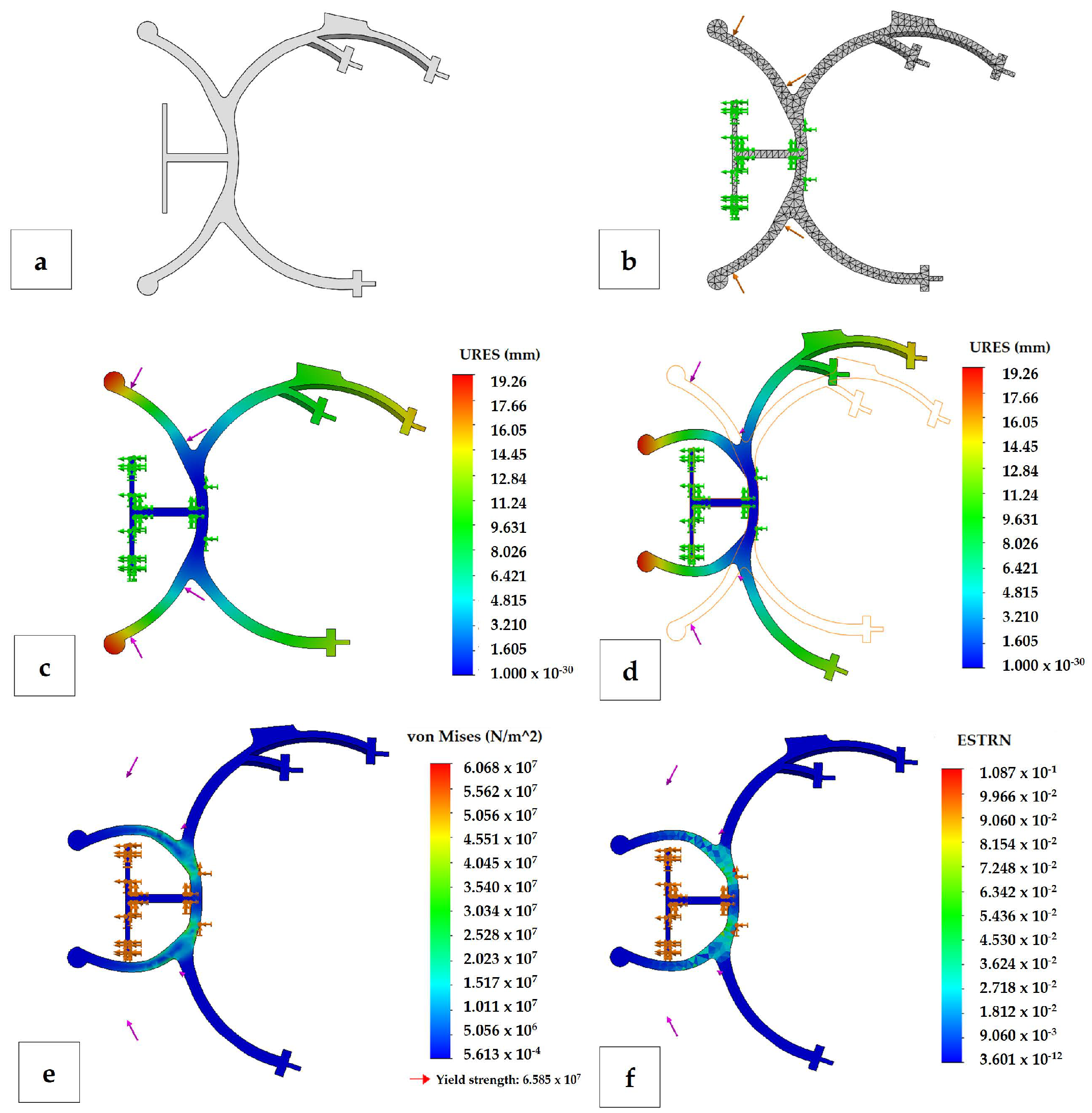
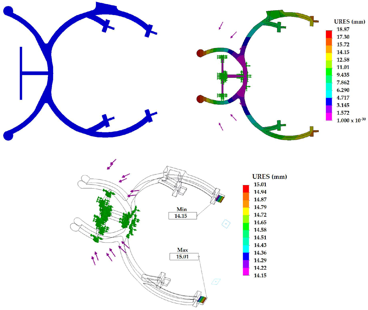
Figure 2 shows some simulation steps and the results obtained for TPU when applying a force of 35 N, also observing the way in which the structure is deformed.
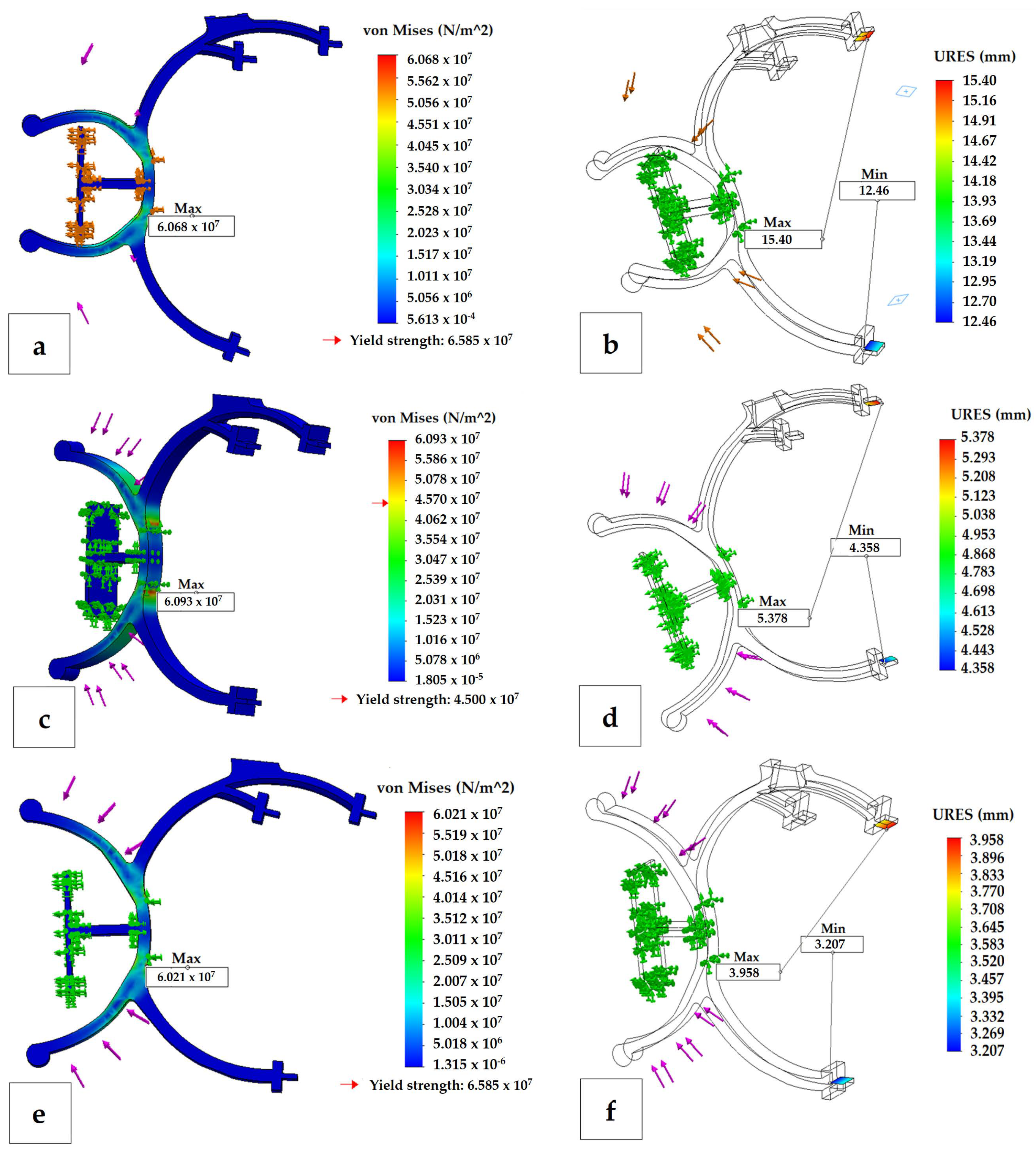
Figure 3 shows the results obtained for the mechanical characteristics of interest: the equivalent Von Mises stresses and the maximum opening or distance/displacement obtained between the two fastening elements. The Von Mises stresses obtained for all three investigated materials are presented in Figure 3a,c,e, and it can be observed that for the ABS material the value of Von Mises stress at 35 N exceeds the yield strength of the material. To obtain the results of the maximum opening of the compliant mechanism as a result of applying the request, it was set from SW to only display the results of the entities of interest, as shown in Figure 3b,d,f, the total distance obtained by summing the resulting displacements of the two clamping elements.
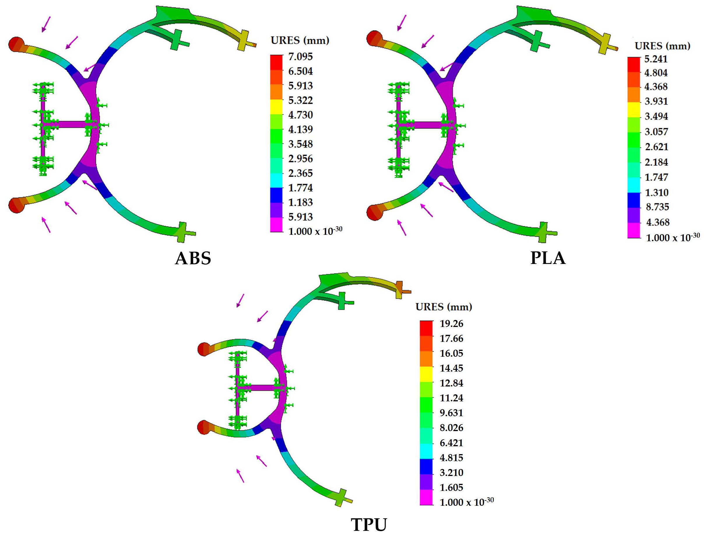
Figure 4 shows the comparative results of the displacements at the same applied force (35 N) for the three materials used in the study, clearly observing the much higher degree of deformation of the compliant mechanism of TPU, especially due to its mechanical properties being much more suitable for this application. Therefore, for the same applied force of 35 N, a maximum aperture of 27.86 mm is obtained for TPU (which corresponds to the real displacement range for the application of the compliant mechanism), a much higher value compared to those obtained for ABS and PLA—9.74 mm and 7.17 mm, respectively. Table 3 shows the simulation results obtained for the three materials studied in a certain force range (5–35 N) for the equivalent Von Mises stresses and the maximum openings of the compliant mechanism. It can be seen from the table, that at applied forces greater than 25 N, for ABS, the Von Mises stresses exceed the material yield limit, which indicates possible plastic deformation in some areas where this value is exceeded; an undesirable aspect for the application of the compliant mechanism.
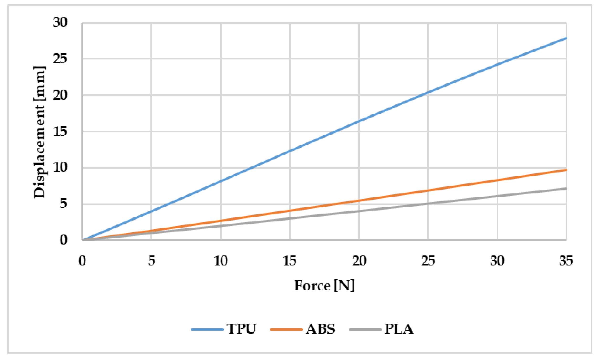
Figure 5 shows the comparative results of the displacements of the fastening elements obtained according to the force for all three studied materials, where the much higher values for TPU of the displacements at the same applied force compared to acrylonitrile butadiene styrene and polylactic acid are clearly highlighted, to conclude that this material seems to be the most suitable candidate for the realization of the fastening systems applied in the field of clinical optometry discussed in this paper. This is due to its special mechanical properties that are manifested by increased elasticity and other important properties that recommend it for this application in the field of optometry. Between PLA and ABS, the former proved to have more suitable properties after simulation tests.
Figure 6 shows the simulation results (35 N applied force) for a constructive variant consisting of four fastening elements, which can be used to fasten circular glasses. In this case, a maximum opening between the outer fasteners of 29.16 mm is obtained at an applied force of 35 N. In both constructive cases (with three and four gripping elements), following the FEM analysis, the most suitable material for the given application is TPU, where the closest displacement compared to the desired displacement is obtained according to theoretical considerations.

3. Physically Developed Prototype of Mechanism

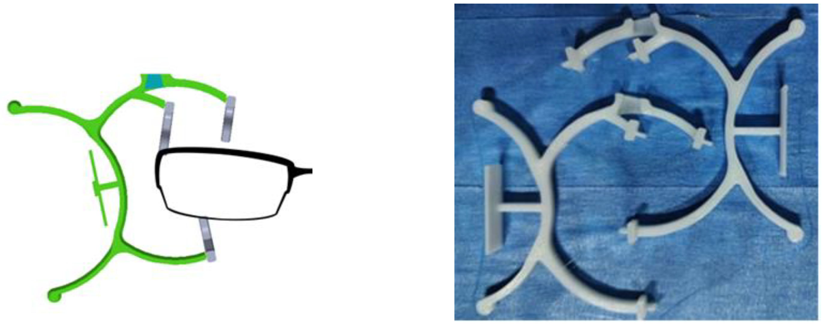
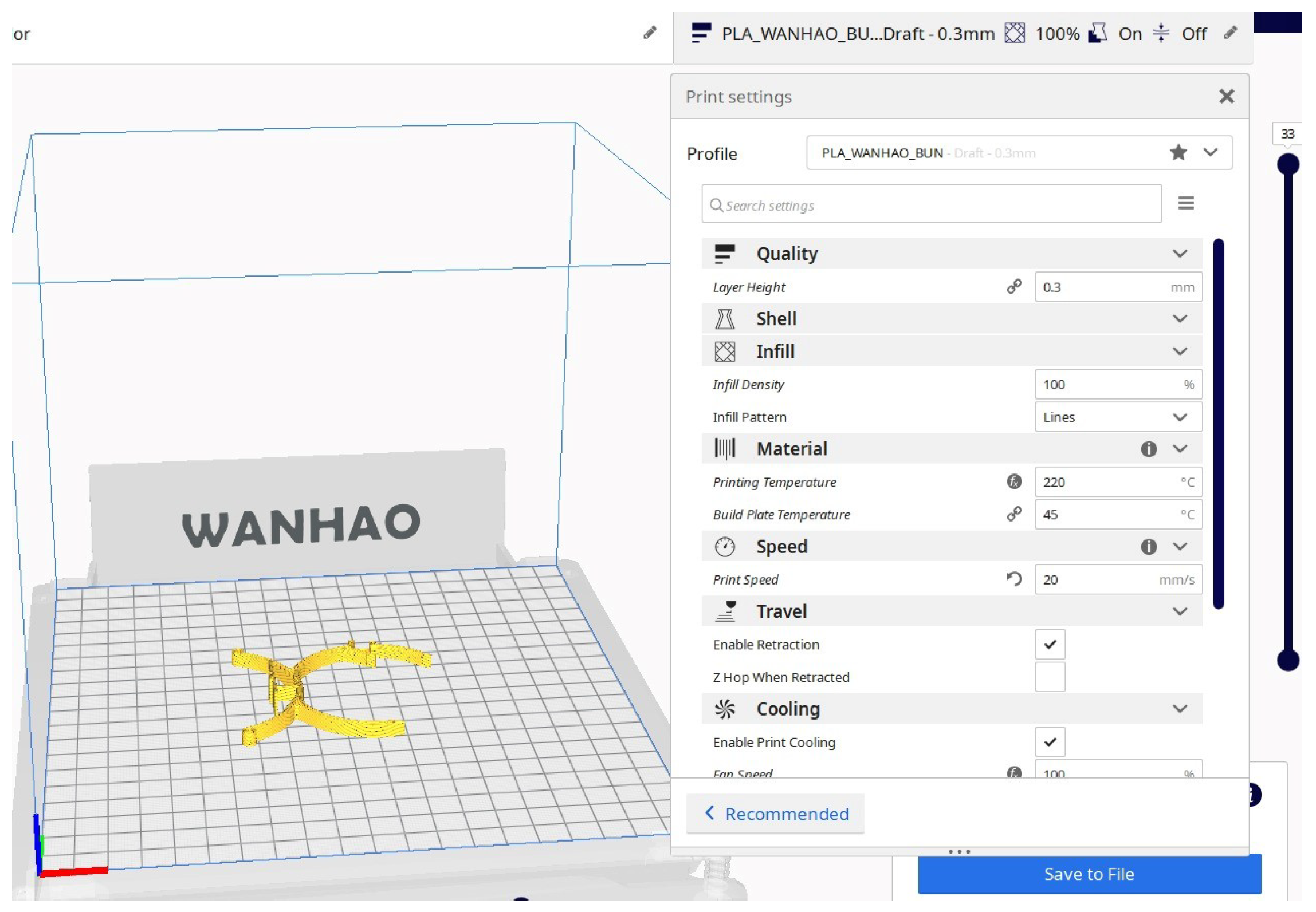
The mechanism was manufactured using FDM technology from PLA, ABS, and TPU (Figure 7). When using each material, the particularities of each thermoplastic used were considered. No special problems were encountered in the realization of the three variants, but noticeable differences were observed between the times necessary to print the mechanisms. Thus, the TPU material is the most expensive in terms of time, being necessary to use it at very low speeds (10–20 mm/s-Figure 8), compared to PLA/ABS (30–35 mm/s), the results being similar in terms of aesthetics.
As expected from the point of view of the use of the materials presented, the differences between the three are obvious. For the following conclusions, a series of tests were performed with the help of human users. Their automatic testing was performed in the next part of the paper.
The PLA material variants used give way after several uses, but are the easiest to obtain and, from an aesthetic point of view, they correspond to the requirements. The approximate weight obtained is 4 g.
The ABS material presents, as expected, problems in terms of realization, it being necessary to add a layer of sacrifice. The results are similar to those obtained for PLA: although appropriate from an aesthetic point of view and with a very wide range of colours, the pieces made do not correspond, in terms of elasticity, to the requirements and give way after several uses.
Thermoplastic polyurethane (TPU)—from the variants used and commercially available, the NinjaTek Armadillo variant was chosen, which was also used for the simulations presented above [38]. Although it presents a series of challenges in terms of use in the FDM process, this material is mechanically the most suitable, obtaining the desired displacements for the forces that can be exerted during use by a human user.
Among the materials used, the best results were obtained for TPU, with the disadvantage of having less pleasant surfaces from an aesthetic point of view, and with some difficulties in printing the parts. This contradicts some of the conditions imposed at the beginning of the work—the possibility of realizing these mechanisms without a specialized training, with the help of common 3D printers. This material is also biocompatible, as stated by the manufacturer.

4. Testing of Manufactured Device

In order to test and validate the structures made by FDM technology, but also to compare the results obtained by simulation with the results of the experimental model, a physical system was developed that simulated the functioning of the proposed mechanisms for the given application. The experimental stand proposed in the paper presents the possibility of fixing the tested part in a support that allows its displacement, especially on the X axis and the rotation around the Z axis of the compliant mechanism. The testing rig was specially made for the tests and is not part of any patent or technical solution. Its purpose was to determine if the mechanism could be used for a reasonable number of times, less than a couple hundred, without it breaking or losing its mechanical characteristics, and testing was continuously performed.
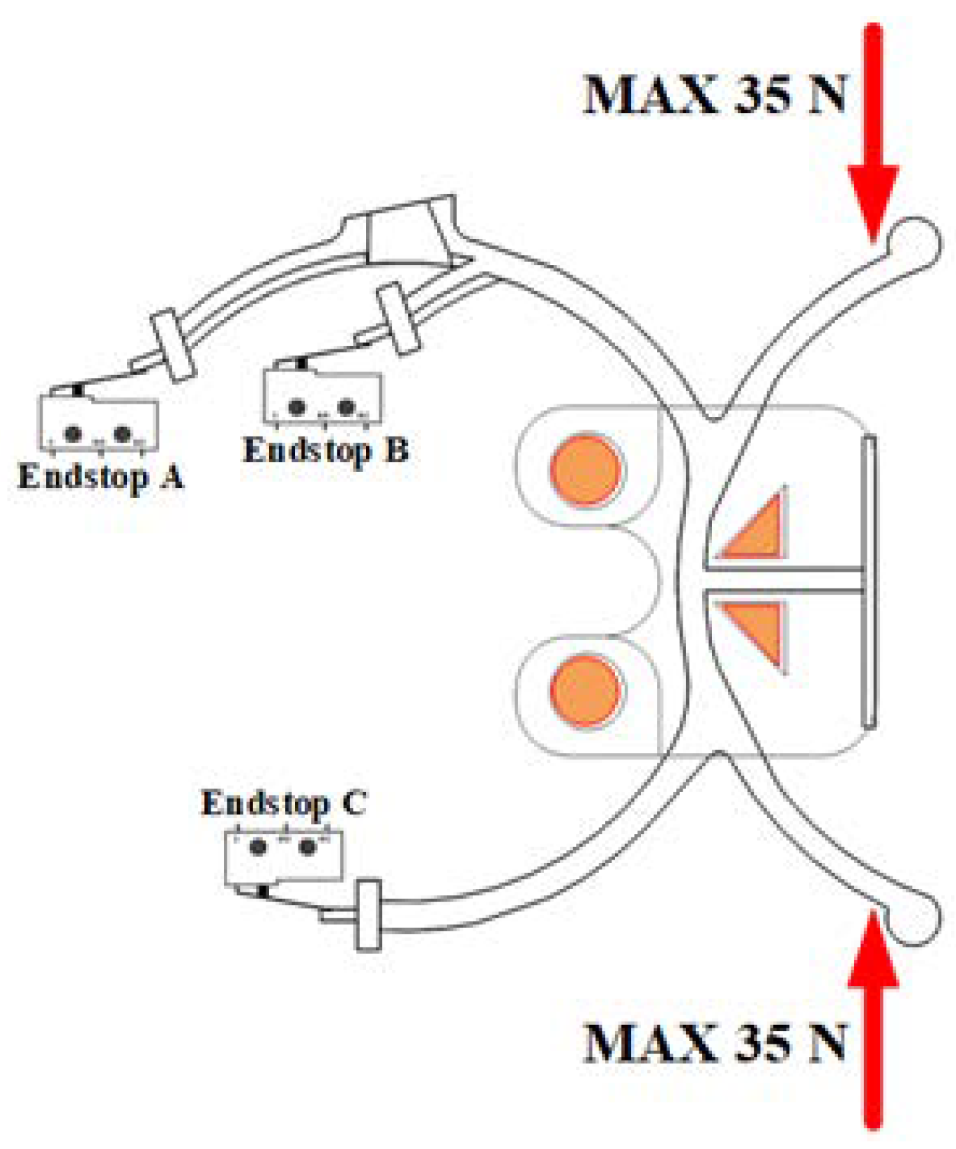
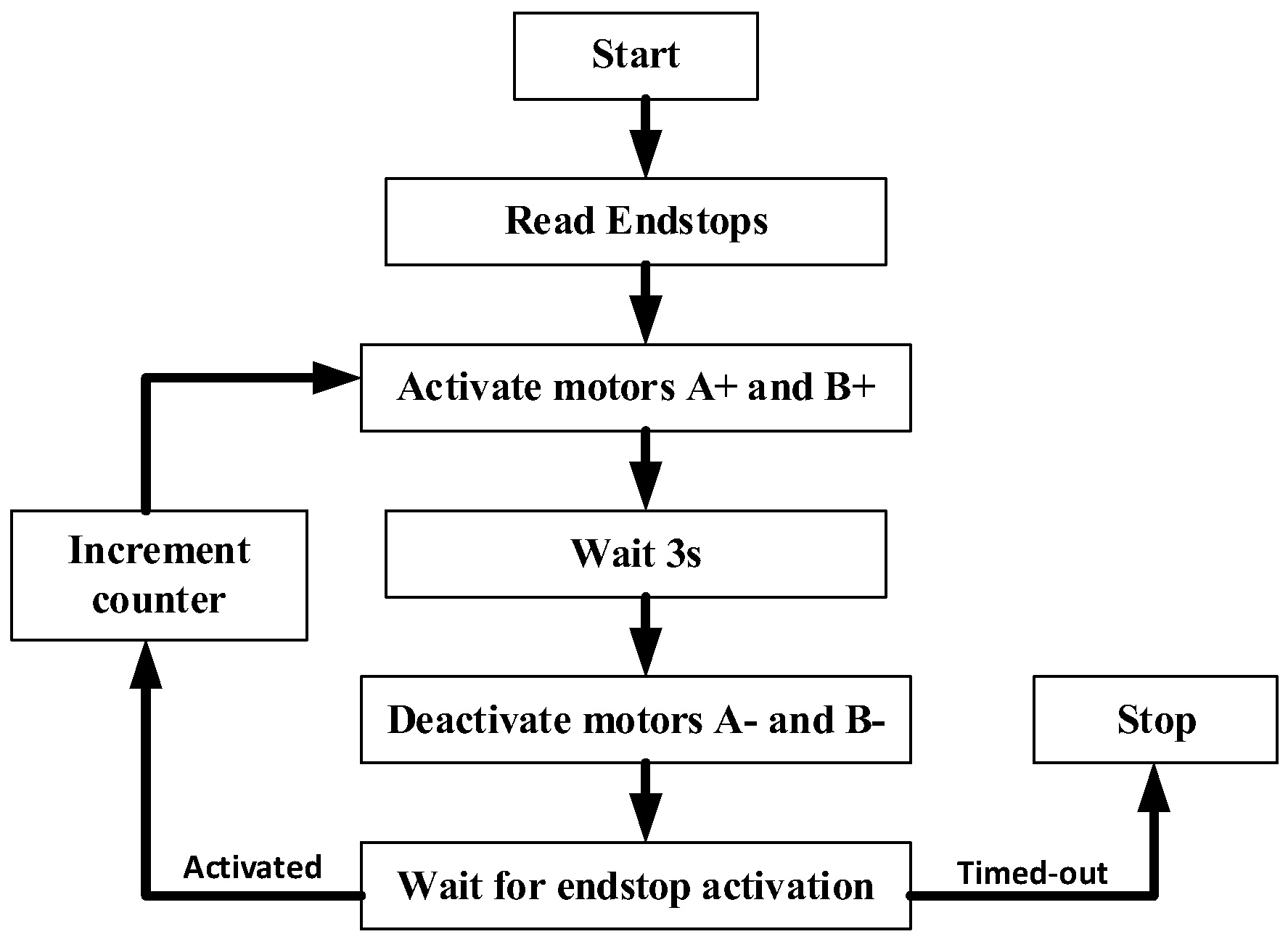
However, the part was not fixed on any axis; the assembly was made with high tolerances. At each of the moving ends of the mechanism, end-of-travel sensors were mounted, as shown, for clarity, as mechanical microswitches in the diagram in Figure 9, but optical sensors in the stand were made. Actuation was conducted with the help of two linear pneumatic motors with double action (Figure 10), dimensioned so as to produce a force of, at most, 35 N at the working pressure (3 bar). The two motors were mounted in opposition on the same Y axis of the system, in the direction of the red arrows in Figure 9. The movement of the two motors simultaneously occurred, according to the proposed control algorithm.
The control and monitoring of the system was conducted with the help of an electronic system based on an ESP microcontroller, together with the signal adaptation electronics necessary for the interface with the distributors and limit switches used.
Figure 11 shows a schematic diagram of the algorithm implemented for control.
Figure 12a shows the complete scheme of the system made for testing the parts. A simple PC-level application was developed to control the application. This opens a bidirectional TCP port and allows for the initiation of commands and the reception of data from the limit switches mounted on the construction. The advance and withdrawal strokes along with the signals from the end-of-travel sensors were counted at the controller level and transmitted to the PC.
Figure 12b shows an overview of the test stand made for testing this solution and obtained preliminary results to confirm those obtained by the simulation. It contains the elements presented above and works according to those described.
As expected, the system poorly performs for both ABS and PLA, with minimal elasticity of the parts, and they fail after only a few uses. TPU parts, however, perform generally better, as tested, with no obvious issues to the mechanism after a few tries.

5. Conclusions

This paper presents the the right choice of materials, a finite element analysis simulation, technologies, and the realization and testing of mechanisms to be used in the field of optometry. Following the research, the chosen thermoplastic polyurethane (TPU) material proved to be the most suitable, both in terms of elastic properties, biocompatibility, the possibility of recycling materials, and all criteria stated at the beginning of the paper. From a scientific standpoint, the model is set to serve as part of a low-cost, low-maintenance system with a reasonable error parameter needed for custom-built lenses for users with specific needs. This is set to lower the cost of such procedures, which is currently high, and is also expected to assist in giving better medical care to a larger array of individuals.
In the future, we want to test this mechanism in a complete set, but also perform tests with as many patients as possible, so that the possible problems related to the use and implementation of the mechanism described in this paper can be determined and solved.

Author Contributions

Conceptualization, V.C. and E.M.; methodology, V.C. and B.G.; software, V.C. and B.G.; validation, E.M. and D.B.; formal analysis, E.M. and D.B.; investigation, D.B. and V.C.; resources, B.G. and E.M.; writing—original draft preparation, V.C., E.M., D.B. and B.G.; writing—review and editing V.C., E.M., D.B. and B.G. All authors have read and agreed to the published version of the manuscript.

Funding

This research received no external funding.

Institutional Review Board Statement

Not applicable.

Informed Consent Statement

Not applicable.

Data Availability Statement

Not applicable.

Conflicts of Interest

The authors declare no conflict of interest.

References

  1. Nilsen, T.; Hermann, M.; Eriksen, C.; Dagfinrud, H.; Mowinckel, P.; Kjeken, I. Grip force and pinch grip in an adult population: Reference values and factors associated with grip force. Scand. J. Occup. Ther. 2011, 19, 288–296. [Google Scholar] [CrossRef]
  2. VisionFit Dispensing System™ (VFDS). Available online: https://www.luzerneoptical.com/vfds-visionfit-dispensing-system.html (accessed on 6 January 2023).
  3. What Is OptikamPad? Available online: https://www.optikam.com/ (accessed on 6 January 2023).
  4. EssilorPRO. Available online: https://www.essilorpro.com/ (accessed on 6 January 2023).
  5. ZEISS i.Terminal 2. Available online: https://www.zeiss.com/vision-care/int/ecp/products/instruments-technology/zeiss-i-terminal-2.html (accessed on 6 January 2023).
  6. Thompson, M.; Moroni, G.; Vaneker, T.; Fadel, G.; Campbell, R.; Gibson, I.; Bernard, A.; Schulz, J.; Graf, P.; Ahuja, B.; et al. Design for Additive Manufacturing: Trends, opportunities, considerations, and constraints. CIRP Ann. 2016, 65, 737–760. [Google Scholar] [CrossRef] [Green Version]
  7. Farooque, R.; Asjad, M.; Rizvi, S. A current state of art applied to injection moulding manufacturing process—A review. Mater. Today Proc. 2021, 43, 441–446. [Google Scholar] [CrossRef]
  8. Singh, G.; Verma, A. A Brief Review on injection moulding manufacturing process. Mater. Today Proc. 2017, 4, 1423–1433. [Google Scholar] [CrossRef]
  9. Hamidi, M.F.F.A.; Harun, W.S.W.; Samykano, M.; Ghani, S.A.C.; Ghazalli, Z.; Ahmad, F.; Sulon, A.B. A review of biocompatible metal injection moulding process parameters for biomedical applications. Mater. Sci. Eng. C 2017, 78, 1263–1276. [Google Scholar] [CrossRef] [Green Version]
  10. Dehghan-Manshadi, A.; Yu, P.; Dargush, M.; Stjohn, D.; Qian, M. Metal injection moulding of surgical tools, biomaterials and medical devices: A review. Powder Technol. 2020, 364, 189–204. [Google Scholar] [CrossRef]
  11. Mazzoli, A. Selective laser sintering in biomedical engineering. Med. Biol. Eng. Comput. 2013, 51, 245–256. [Google Scholar] [CrossRef]
  12. Kumar, S. Selective laser sintering: A qualitative and objective approach. JOM 2003, 55, 43–47. [Google Scholar] [CrossRef]
  13. Schmidt, M.; Pohle, D.; Rechtenwald, T. Selective Laser Sintering of PEEK. CIRP Ann. 2007, 56, 205–208. [Google Scholar] [CrossRef]
  14. Olakanmi, E.; Cochrane, R.; Dalgarno, K. A review on selective laser sintering/melting (SLS/SLM) of aluminium alloy powders: Processing, microstructure, and properties. Prog. Mater. Sci. 2015, 74, 401–477. [Google Scholar] [CrossRef]
  15. León-Cabezas, M.; Martínez-García, A.; Varela-Gandía, F. Innovative advances in additive manufactured moulds for short plastic injection series. Procedia Manuf. 2017, 13, 732–737. [Google Scholar] [CrossRef]
  16. Medellin, A.; Du, W.; Miao, G.; Zou, J.; Pei, Z.; Ma, C. Vat Photopolymerization 3D Printing of Nanocomposites: A Literature Review. J. Micro Nano-Manuf. 2019, 7, 031006. [Google Scholar] [CrossRef]
  17. Aduba, D.C., Jr.; Margaretta, E.D.; Marnot, A.E.; Heifferon, K.V.; Surbey, W.R.; Chartrain, N.A.; Whittington, A.R.; Long, T.E.; Williams, C.B. Vat photopolymerization 3D printing of acid-cleavable PEG-methacrylate networks for biomaterial applications. Mater. Today Commun. 2019, 19, 204–211. [Google Scholar] [CrossRef]
  18. Chartrain, N.A.; Williams, C.B.; Whittington, A.R. A review on fabricating tissue scaffolds using vat photopolymerization. Acta Biomater. 2018, 74, 90–111. [Google Scholar] [CrossRef]
  19. Dhinakaran, V.; Manoj Kumar, K.; Bupathi Ram, P.; Ravichandran, M.; Vinayagamoorthy, M. A review on recent advancements in fused deposition modelling. Mater. Today Proc. 2020, 27, 752–756. [Google Scholar] [CrossRef]
  20. Parulski, C.; Jennotte, O.; Lechanteur, A.; Evrard, B. Challenges of fused deposition modeling 3D printing in pharmaceutical applications: Where are we now? Adv. Drug Deliv. Rev. 2021, 175, 113810. [Google Scholar] [CrossRef]
  21. Cailleaux, S.; Sanchez-Ballester, N.M.; Gueche, Y.A.; Bataille, B.; Soulairol, I. Fused Deposition Modeling (FDM), the new asset for the production of tailored medicines. J. Control. Release 2021, 330, 821–841. [Google Scholar] [CrossRef]
  22. Bakır, A.A.; Atik, R.; Özerinç, S. Mechanical properties of thermoplastic parts produced by fused deposition modeling: A review. Rapid Prototyp. J. 2021, 27, 537–561. [Google Scholar] [CrossRef]
  23. Doshi, M.; Mahale, A.; Kumar Singh, S.; Deshmukh, S. Printing parameters and materials affecting mechanical properties of FDM-3D printed Parts: Perspective and prospects. Mater. Today Proc. 2022, 50, 2269–2275. [Google Scholar] [CrossRef]
  24. Rezaeian, P.; Ayatollahi, M.R.; Nabavi-Kivi, A.; Razavi SM, J. Effect of printing speed on tensile and fracture behavior of ABS specimens produced by fused deposition modelling. Eng. Fract. Mech. 2022, 266, 108393. [Google Scholar] [CrossRef]
  25. Azadi, M.; Dadashi, A.; Dezianian, S.; Kianifar, M.; Torkaman, S.; Chiyani, M. High-cycle bending fatigue properties of additive-manufactured ABS and PLA polymers fabricated by fused deposition modeling 3D-printing. Forces Mech. 2021, 3, 100016. [Google Scholar] [CrossRef]
  26. Peterson, A.M. Review of acrylonitrile butadiene styrene in fused filament fabrication: A plastics engineering-focused perspective. Addit. Manuf. 2019, 27, 363–371. [Google Scholar] [CrossRef]
  27. Vidakis, N. Sustainable additive manufacturing: Mechanical response of acrylonitrile-butadiene-styrene over multiple recycling processes. Sustainability 2020, 12, 3568. [Google Scholar] [CrossRef]
  28. Singhvi, M.S.; Zinjarde, S.S.; Gokhale, D.V. Polylactic acid: Synthesis and biomedical applications. J. Appl. Microbiol. 2019, 127, 1612–1626. [Google Scholar] [CrossRef] [Green Version]
  29. Li, G.; Zhao, M.; Xu, F.; Yang, B.; Li, X.; Meng, X.; Teng, L.; Sun, F.; Li, Y. Synthesis and biological application of polylactic acid. Molecules 2020, 25, 5023. [Google Scholar] [CrossRef]
  30. Casalini, T.; Rossi, F.; Castrovinci, A.; Perale, G. A Perspective on Polylactic Acid-Based Polymers Use for Nanoparticles Synthesis and Applications. Front. Bioeng. Biotechnol. 2019, 7, 259. [Google Scholar] [CrossRef]
  31. Hamad, K.; Kaseem, M.; Ayyoob, M.; Joo, J.; Deri, F. Polylactic acid blends: The future of green, light and tough. Prog. Polym. Sci. 2018, 85, 83–127. [Google Scholar] [CrossRef]
  32. Xiao, J.; Gao, Y. The manufacture of 3D printing of medical grade TPU. Prog. Addit. Manuf. 2017, 2, 117–123. [Google Scholar] [CrossRef] [Green Version]
  33. Verstraete, G.; Samaro, A.; Grymonpré, W.; Vanhoorne, V.; Van Snick, B.; Boone, M.N.; Hellemans, T.; Van Hoorebeke, L.; Remon, J.P.; Vervaet, C. 3D printing of high drug loaded dosage forms using thermoplastic polyurethanes. Int. J. Pharm. 2018, 536, 318–325. [Google Scholar] [CrossRef]
  34. Harris, C.G.; Jursik, N.J.; Rochefort, W.E.; Walker, T.W. Additive Manufacturing with Soft TPU—Adhesion Strength in Multimaterial Flexible Joints. Front. Mech. Eng. 2019, 5, 37. [Google Scholar] [CrossRef] [Green Version]
  35. De la Rosa, S.; Mayuet, P.F.; Méndez Salgueiro, J.R.; Rodríguez-Parada, L. Design of Customized TPU Lattice Structures for Additive Manufacturing: Influence on the Functional Properties in Elastic Products. Polymers 2021, 13, 4341. [Google Scholar] [CrossRef]
  36. Moraru, E. Research on the Realization of Dental Prostheses by Selective Laser Deposition and Other Additive Technologies. Ph.D. Thesis, Politehnica University of Bucharest, Bucharest, Romania, 2021. (In Romanian). [Google Scholar]
  37. Besnea, D.; Rizescu, C.I.; Rizescu, D.; Comeaga, D.; Ciobanu, R.; Moraru, E. Study of deflection behaviour of 3D printed leaf springs. In Proceedings of the 8th International Conference on Advanced Concepts in Mechanical Engineering, Iasi, Romania, 7–8 June 2018; Volume 444, p. 042008. [Google Scholar]
  38. Armadillo Technical Data Sheet. Available online: https://ninjatek.com/shop/armadillo/ (accessed on 6 January 2023).
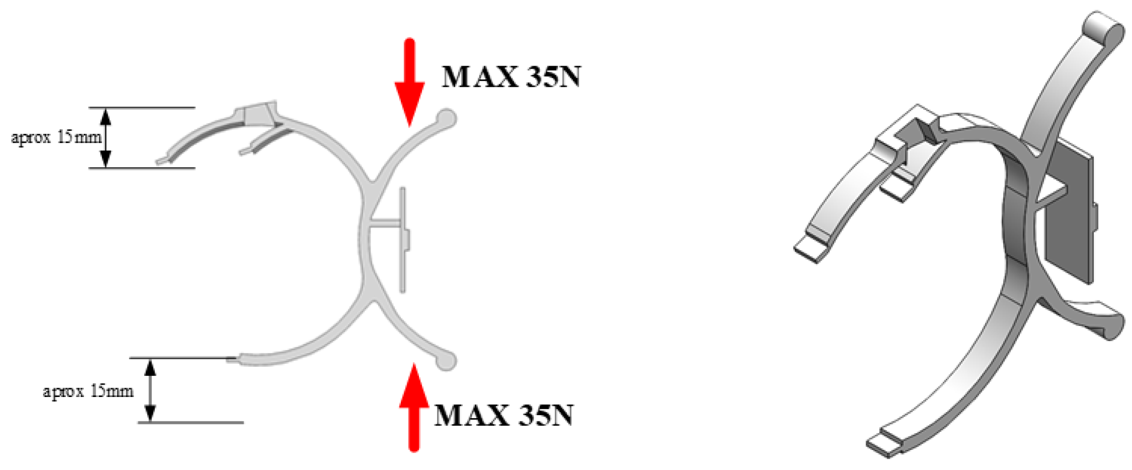
Figure 1. General view of mechanism.
Applsci 13 02859 g001
Figure 2. Some steps of FEM simulation of the TPU compliant mechanism at 35 N applied force: (a)-geometry model designing; (b)-fixing geometry, applying force and meshing; (c)-displacement results (undeformed model); (d)-displacement results (deformed model); (e)-Von Mises stress results; (f)-strain results (the arrows represent the mode of action of the force).
Applsci 13 02859 g002
Figure 3. Comparison of obtained mechanical characteristics results for three investigated materials (35 N applied force in all cases): (a)-TPU mechanism Von Mises stress results; (b)-TPU mechanism displacement results between gripping elements; (c)-ABS mechanism Von Mises stress results; (d)-ABS mechanism displacement results between gripping elements; (e)-PLA mechanism Von Mises stress results; (f)-PLA mechanism displacement results between gripping elements.
Applsci 13 02859 g003
Figure 4. Comparison of resulted displacement and degree deformation at the same applied force-35 N for all investigated materials.
Applsci 13 02859 g004
Figure 5. Comparison of force-displacement characteristics for investigated materials.
Applsci 13 02859 g005
Figure 6. Obtained results for compliant mechanism with four gripping elements.
Applsci 13 02859 g006
Figure 7. Principle of operation and PLA manufactured compliant mechanism.
Applsci 13 02859 g007
Figure 8. Working parameters used for compliant mechanism.
Applsci 13 02859 g008
Figure 9. Principle schematics of testing.
Applsci 13 02859 g009
Figure 10. Pneumatic actuation schematics.
Applsci 13 02859 g010
Figure 11. Control algorithm schematics.
Applsci 13 02859 g011
Figure 12. (a)—Control schematics; (b)—Real system.
Applsci 13 02859 g012
Table 1. Several proposed designed shapes for the compliant mechanism.
ModelExplanation
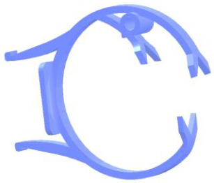
Applsci 13 02859 i001Version 1—Loosely based on a half open contour of glasses frames, the two-sided handles allow force to be applied, and thus obtain an almost vertical movement of the three prongs in the right of the picture. These three points will allow for secure fastening to the frames. The model was found lacking for multiple reasons, especially due to the fact that applying the necessary force was difficult.
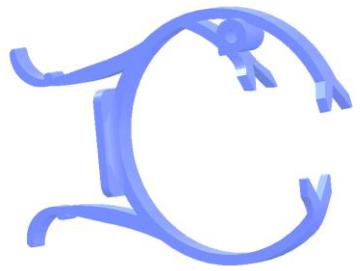
Applsci 13 02859 i002Version 2—The improved design of the handles allows force to be applied much more easily, and thus obtain a better overall behaviour. However, in this version, it was first noticed that the new support interfered with the patient, since the actual body of the marker support system pushed against the patient’s face.
Applsci 13 02859 i003Version 3—Prongs were extended laterally to move the entire support in a plane parallel to the user’s glasses, and as such, no longer pushed against the patient’s face. Modifications were also made to the handles with minor improvements to the overall usability of the system.
Applsci 13 02859 i004Version 4—Further improvements were made to the design, and handles were reverted to the initial profile, as the previous one was proven to fail under repeated stress in terms of both simulations and practical use.
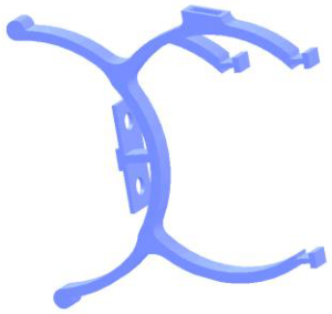
Applsci 13 02859 i005Version 5—To allow for a larger opening of the device, the orientation of the handles was changed. Furthermore, the prongs were made detachable—this is due to the technological aspects of FDM, as it allows for much better control of the settings used for each part of the frame. Furthermore, since the prongs are in direct contact with the frames, they must be coated to ensure that they do not scratch the surface.
Applsci 13 02859 i006Version 6—Final version of the design, with minor modifications in terms of the retention system for prongs, infill, as well as very small dimensional changes. This is the version that has been used in the paper.
Table 2. Properties of materials used in the study.
PropertyABSPLATPU
Density1.02 g/cm31.252 g/cm31.18 g/cm3
Young Modulus1.18 GPa1.59 GPa0.396 GPa
Poisson ratio0.350.360.3897
Yield strength45 MPa70 MPa65.85 MPa
Table 3. Obtained results for Von Mises stress and displacement between gripping elements.
F (N)TPU (σy = 65.85 MPa)ABS (σy = 45 MPa)PLA (σy = 70 MPa)
ymax [mm]σmax [MPa]ymax [mm]σmax [MPa]ymax [mm]σmax [MPa]
54.038.41.358.351.038.3
108.1617.162.7216.842.0116.72
1512.3226.114.1125.473.0325.25
2016.4235.075.5134.214.0533.87
2520.443.876.9143.055.0942.58
3024.2352.458.3251.966.1251.36
3527.8660.689.7460.937.1760.21
Disclaimer/Publisher’s Note: The statements, opinions and data contained in all publications are solely those of the individual author(s) and contributor(s) and not of MDPI and/or the editor(s). MDPI and/or the editor(s) disclaim responsibility for any injury to people or property resulting from any ideas, methods, instructions or products referred to in the content.