Article

Analysis of Unexpected Leaks in AISI 316L Stainless Steel Pipes Used for Water Conduction in a Port Area

1
LADICIM (Laboratory of Materials Science and Engineering), University of Cantabria, E.T.S. de Ingenieros de Caminos, Canales y Puertos, Av/Los Castros 44, 39005 Santander, Spain
2
INESCO INGENIEROS S.L., Centro Desarrollo Tecnológico de la Universidad de Cantabria (CDTUC), Fase B, Av/Los Castros 44, 39005 Santander, Spain
3
GIA (Environmental Engineering Group), University of Cantabria, E.T.S. de Ingenieros de Caminos, Canales y Puertos, Av/Los Castros 44, 39005 Santander, Spain
*
Authors to whom correspondence should be addressed.
Appl. Sci. 2023, 13(4), 2598; https://doi.org/10.3390/app13042598
Submission received: 26 January 2023 / Revised: 13 February 2023 / Accepted: 15 February 2023 / Published: 17 February 2023

Abstract

:
This paper clarifies the causes of a corrosion process observed in austenitic stainless-steel pipes, grade 316L, used for conducting freshwater in a port area. During the pressure test of the installation, before it was put into service, about five months after its construction, a loss of pressure was detected due to leaks of the fluid contained and the presence of corrosion damage on the wall of the tubes, in some cases even passing through the thickness of the tube. An analysis of the chemical composition of the pipe material was carried out, as well as semi-quantitative analysis of the chemical composition of the deposits in the defects, and a culture of sulfate-reducing bacteria (SRB) in Kliguer medium of the stagnant waters within the facility. All this makes it possible to conclude that the observed process fits within the so-called microbiologically induced corrosion (MIC), and, in all probability, it can be affirmed that this process is promoted by the presence and proliferation of sulfate-reducing bacteria (SRB).

1. Introduction

1.1. General Background

Nowadays, when building or reconditioning new facilities or infrastructures exposed to aggressive environments, designers tend to recommend the use of stainless steels (SS) for such purposes. It is true that stainless steels, mainly (AISI) 304, 304L, 316, and 316L, are well-known for their excellent corrosion resistance and good mechanical properties, so they have been widely used in a large number of aggressive environments and applications [1], most often with good results and performance. However, it is also true that SS are not free of corrosion issues, as it is mistakenly believed in practice. Thus, in many cases, it is not considered necessary to take any precautions or carry out a maintenance plan on the installation to fight against corrosion issues during the construction and/or exploitation phases; this fact has led to important economic losses due to in-service failures, or even during the construction phase, in a non-negligible number of cases. In this sense, different strategies have been proposed to avoid corrosion issues in this type of steel, including anodic protection (e.g., [2]), cathodic protection (e.g., [3,4]), and the use of protective coatings, such as composite electrochemical coatings (e.g., [5,6,7]) and cold spray coatings (e.g., [8]), among others.
Failure processes in metallic and non-metallic pipeline systems are extensively reported in the literature, covering a wide variety of failure mechanisms that include, for example, plastic collapse from local thin areas [9], brittle fracture [10], fatigue [11,12], creep [13], and corrosion processes [14,15]. When dealing with metallic pipelines used in water conduction systems, the main cause (not unique) of failures and leaks is corrosion, which may be additionally associated with non-adequate material selection, non-standardized construction processes, poor maintenance, etc. [16].
Stainless steels are very commonly used for applications in the marine environment, which is one of the most corrosive natural environments in the world. Moreover, due to the influence of corrosive factors, such as temperature, dissolved oxygen, Cl, and pH, metals (including stainless steels) operating in the marine environment usually suffer from pitting corrosion, crevice corrosion, or stress corrosion processes, among others. This restricts the performance reliability of stainless steels in real applications [17,18]. In addition, the microorganisms living in marine environments have a strong impact on the corrosion behavior of metallic materials [19]. The bacteria attaching and multiplying on material surfaces can significantly change the interface properties of the material by physical or/and chemical means, which is known as microbiologically influenced corrosion (MIC) [20].
At the same time, MIC can take place in environments and working conditions where there are no other corrosion processes taking place, or it can appear in combination with other corrosion modes. More importantly, microorganisms can accelerate the kinetics of anodic/cathodic corrosion reactions in such a way that they can be viewed as “catalytic” entities. Microorganisms are also known to induce a localized attack, including dealloying, pitting, localized galvanic corrosion, and stress corrosion cracking [21].
The economic costs associated with MIC in buried pipelines, marine, oil and gas, and other chemical plants are enormous. MIC-induced problems in buried pipelines/equipment have attracted a great deal of attention all around the world [21]. Some of the main concerns when facing MIC are that, on the one hand, it is a very fast type of corrosion (there are examples of pipes corroded in months-to-a-year timeframes) and, on the other hand, once it has started, it is very difficult to stop it and to guarantee the integrity of the affected piping system.

1.2. Case Background

Despite being a well-known issue, the aforementioned problems and premature failures of pipelines systems still occur nowadays. As an example, the failure analysis of a AISI 316L grade stainless steel piping system for freshwater conduction installed in the Port of Santander, in the north of Spain, is carried out in this work. The geometry of the conduction is: 10S Pipe 8 Inch (DN 200 mm), which has 211.58 mm and 219.10 mm of inner and outer diameters, and, therefore, 3.76 mm of wall thickness. The different tubes employed were joined by welding. The failure of the system was detected before its commissioning, when difficulties arose during the pressure test, around five months after its installation. During this time, it was assumed that the system was completely empty, without any type of water inside, according to the construction company’s indications.
The week after the pressure test, the company in charge of construction work proceeded to video-inspect the inside of the pipes. The presence of generalized corrosion damage in the pipe walls was detected, verifying a process of pitting corrosion that, to a greater or lesser degree, was extended through practically all the pipe sections inspected. Interestingly, some of the defects even had a through-wall nature, producing leaks and pressure loss during the pressure test.
Based on all this, the company in charge of the construction works deduced that the corrosion process observed must have developed between the installation and the date of the pressure test (approximately five months), since no corrosion was detected just after the installation of the pipes, neither visually nor in the radiographies of the circumferential welds.
This work, thus, analyzes the failure of the described piping system. Section 2 provides an overview of the experimental methodology, with Section 3 providing a thorough description of the results obtained and the corresponding discussion. Finally, Section 4 gathers the main conclusions.

2. Experimental Approach

In order to clarify the causes of the aforementioned corrosion phenomenon in the AISI 316L stainless steel port piping facility, one 0.6 m long section of the pipe, shown in Figure 1, was extracted from the system. This section contains clear evidence of the commented processes, including a through-wall pitting. Additionally, as it can be observed, for better protection, the pipes were covered with a 0.3 mm thick rubber coating glued to the external surface, which had to be removed for the subsequent analysis trying not to damage the outer face in case it needed to be inspected.
In order to determine the root cause of the deterioration shown in the tubes, the following analyses were carried out:
-
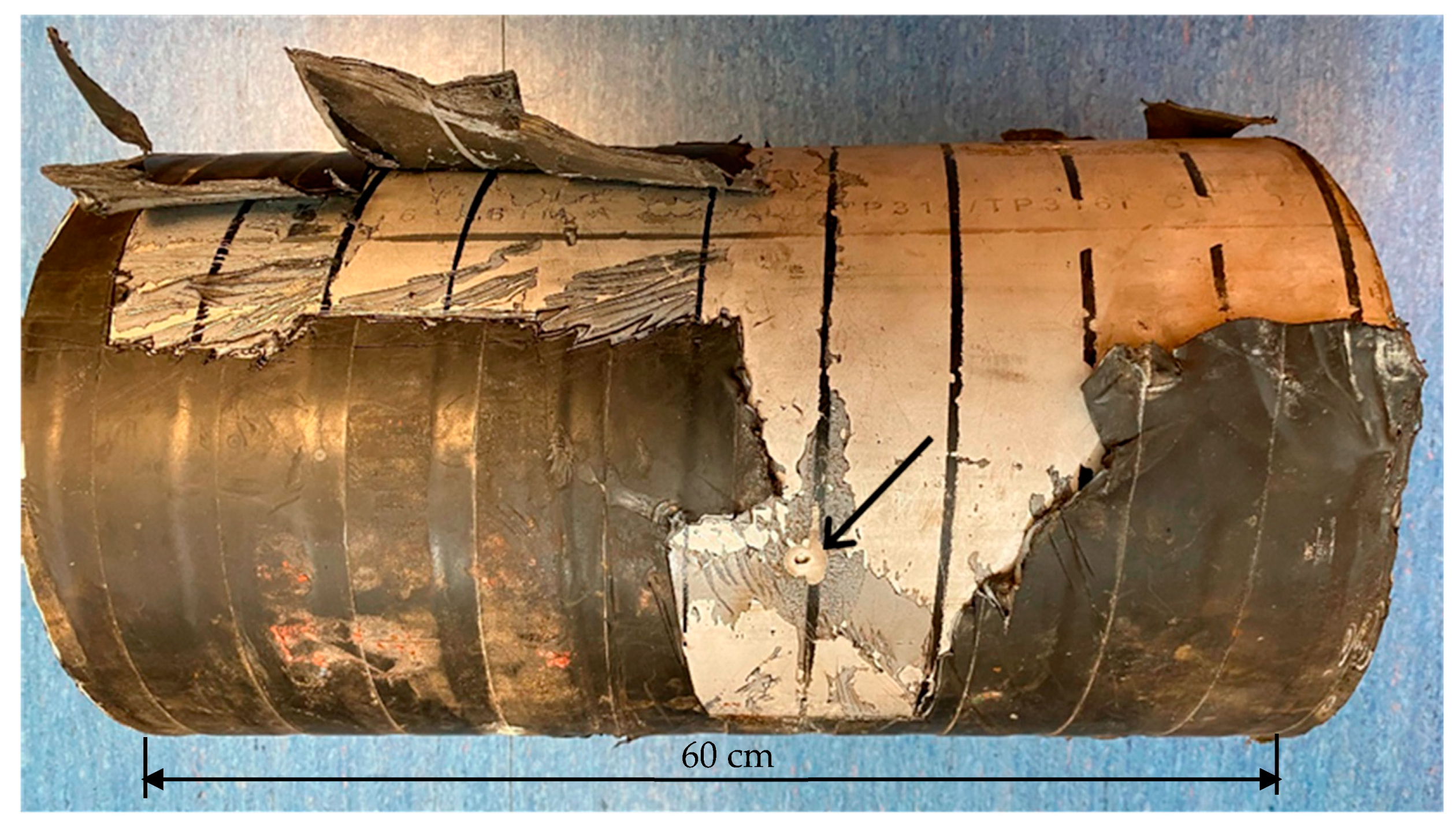
Visual analysis of inner and outer faces of the sample, in order to find any other evidence of damage that is not detected yet.
-
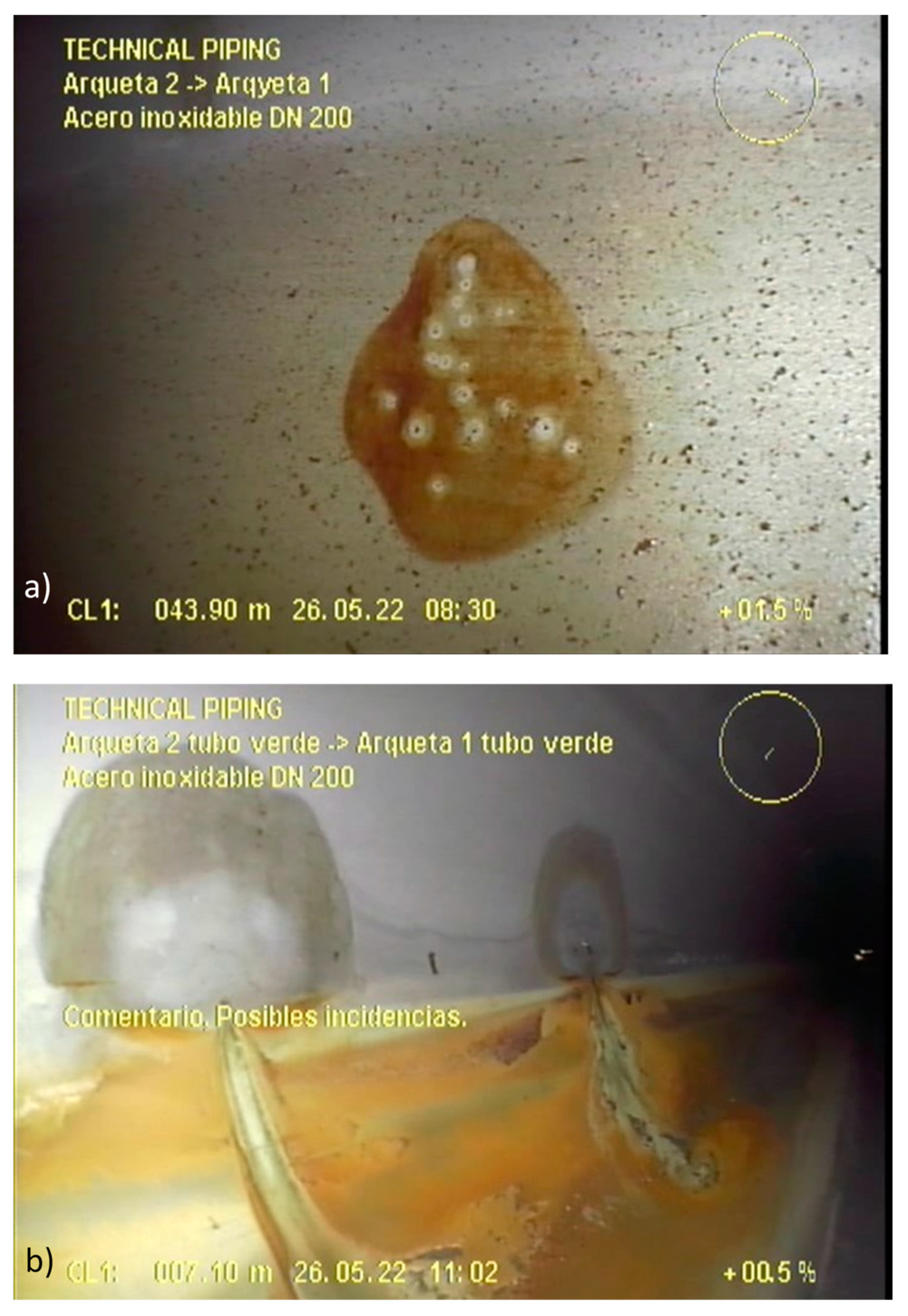
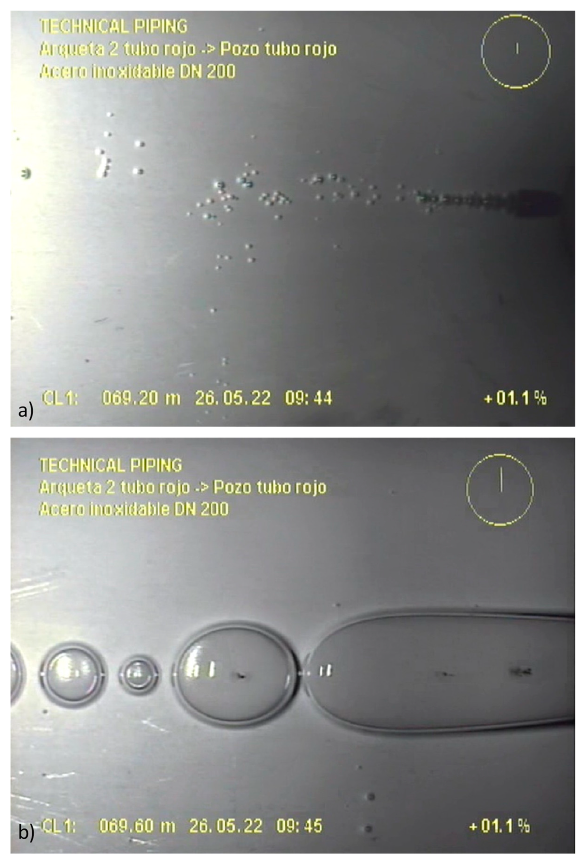
Visual analysis of the video-inspection performed with a robotic submersible camera inside the pipes. There were more than two hours of records, and the most interesting and singular frames were extracted as images and will be shown here.
-
Analysis of the chemical composition of pipe material. This was carried out by spark emission spectroscopy, which allows for the determination of the content of alloying elements with high accuracy.
-
Analysis of the pipe pitting defects by scanning electron microscopy (SEM). The micromechanisms of the pits were analyzed, as well as the semi-quantitative chemical composition of the material surrounding the pits and other singular points of interest, such as grain boundaries or corrosion products.
-
Bacterial culture of the water remaining inside the piping system in an area with an abundance of corrosion products. The sample was analyzed by culturing the mixture of microorganisms present in Kliguer medium and inoculating in a flute beak at 25 °C for one week.
In order to complete such analyses, some sub-samples were extracted from the aforementioned tube by means of a refrigerated metallographic precision cutter, assuring that no alterations were generated in the samples.
Section 3 describes the results obtained and provides some discussion about the different findings.

3. Results and Discussion

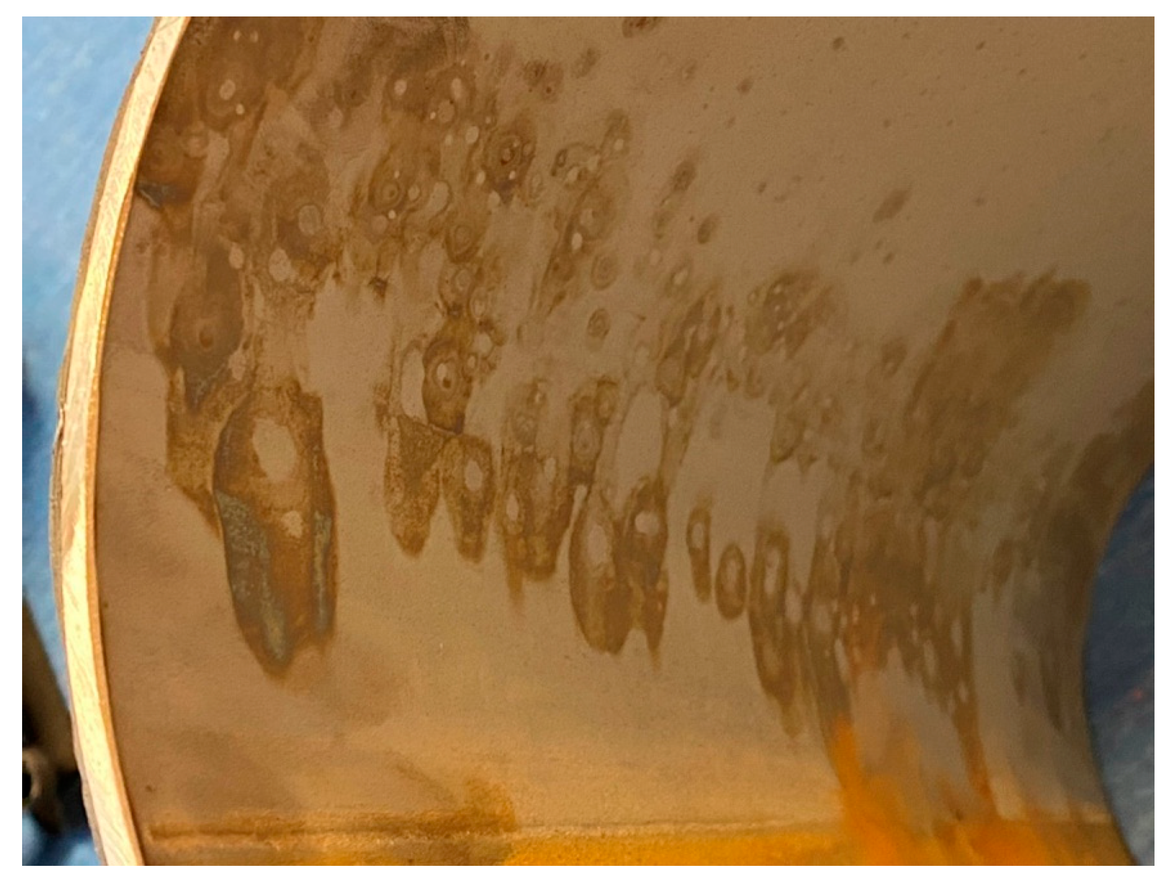
3.1. Visual Inspection of the Sample

In the section of the pipe received in the laboratory, the presence of a through-wall pitting stood out, as shown in Figure 2. This pitting does not follow a radial development from the inner face of the tube to the outer, but rather an intricate one. In the inner area of the tube, in the vicinity of the through-wall pitting, other pitting onsets can be easily distinguished with the naked eye, as presented in Figure 2b.
These defects, as shown in Figure 3, are present to different degrees along the whole inner wall of the sample; however, as observed in Figure 4, they were mainly located in the zone covered by the stagnant water and in a belt just above it, but only on one side. It is noteworthy that the same pattern seems to be observed in all these pitting initiations: pitting surrounded by “clean” material (i.e., non-corroded stainless-steel tone) that extends to an outermost surface crown with evidence of oxidation.
Additionally, in the inner surface of the tube, the signs of corrosion products are evident, characterized by a reddish tone. These corrosion products are deposited in a sector of the pipe (see Figure 4) which may be indicative of an existing (stagnant) water level inside the pipe during some period of the process from the installation to the pressure test.

3.2. Video-Inspection from the Inside of the Piping System

After the pressure test, and due to the unexpected results, a video recording of the interior of the entire piping system was carried out using a robotic camera. The whole recording was provided to the authors of this work. In the several hours of video that were collected, a generalized deterioration due to corrosion is observed, which is of the same type as the one observed in the sample during the visual analysis.
Figure 5 shows examples of the results of the inspections carried out. These records make it possible to verify that the corrosion was a very extended process, with a general level of damage that can be classified as very advanced. Although it can be seen that the level of damage varies from one section to another, there does not seem to be any section of the piping system that is free of the corrosion process. In many of the pits observed (e.g., Figure 5b), a “mushroom-shaped” mark around the defect is evident. These marks may be due to the generation of gas during the corrosion process, which accumulates in pockets, bubbles, or tubercles around the defect and finally bursts (perhaps during the pressure test), leaving the aforementioned “mushroom-shaped” mark printed on the tube wall.
Supporting the previous observation, as presented in Figure 6, in some sequences of the inspection videos, the presence of gas bubbles attached to the inner surface of the pipe can be observed. Here, it is important to note that the figure shows images of parts of the piping system where the water level inside meant that the camera had to be submerged. A more detailed observation of these bubbles reveals the existence of a corrosion pitting in the center of each one of them, as presented in Figure 6b. At the same time, for there to be a separation between gas and water, the existence of a film or membrane that separates both media must be considered.

3.3. Chemical Composition of the Pipes

A sub-sample was extracted from the section of the tube provided in order to determine the chemical composition of the material. It was determined using the spark optical emission spectrometry technique. The results of this analysis are summarized in Table 1, where, as a reference, the expected values for an AISI 316L grade stainless steel have also been incorporated [22].
As can be observed, if the uncertainties of the test technique are considered, all the elements present percentages that may be considered to be within the required ranges, although it should be noted that Cr, Ni, and Mo are close to their corresponding lower limit of the required range. The presence of Cu of around 0.3% can also be observed, which is not among those expressly typified for AISI 316L steel, but its presence cannot automatically classify the alloy as not being in agreement with the specification. In any case, neither the fact that Cr, Ni, and Mo are in the low range, nor the presence of Cu in the amounts reported, can justify the corrosion process observed here.

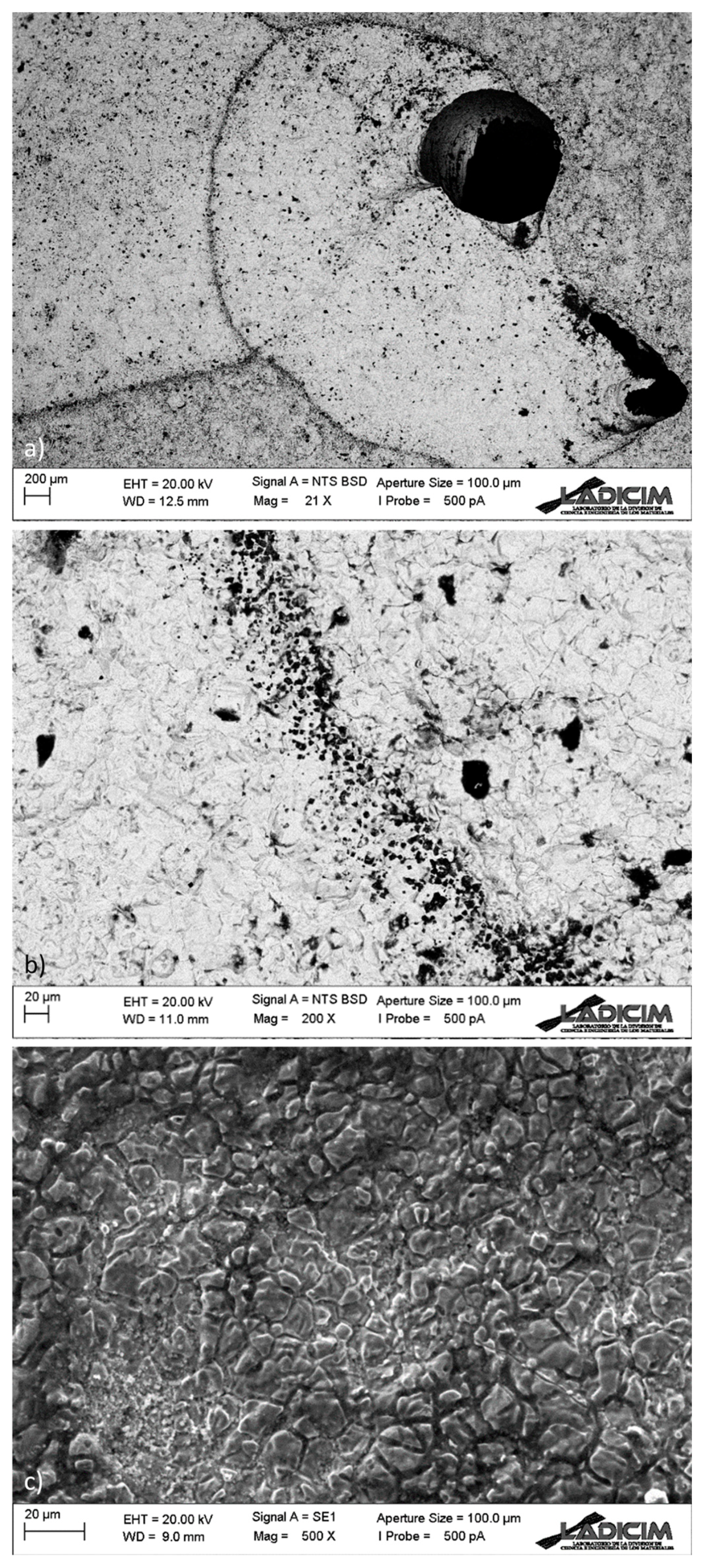
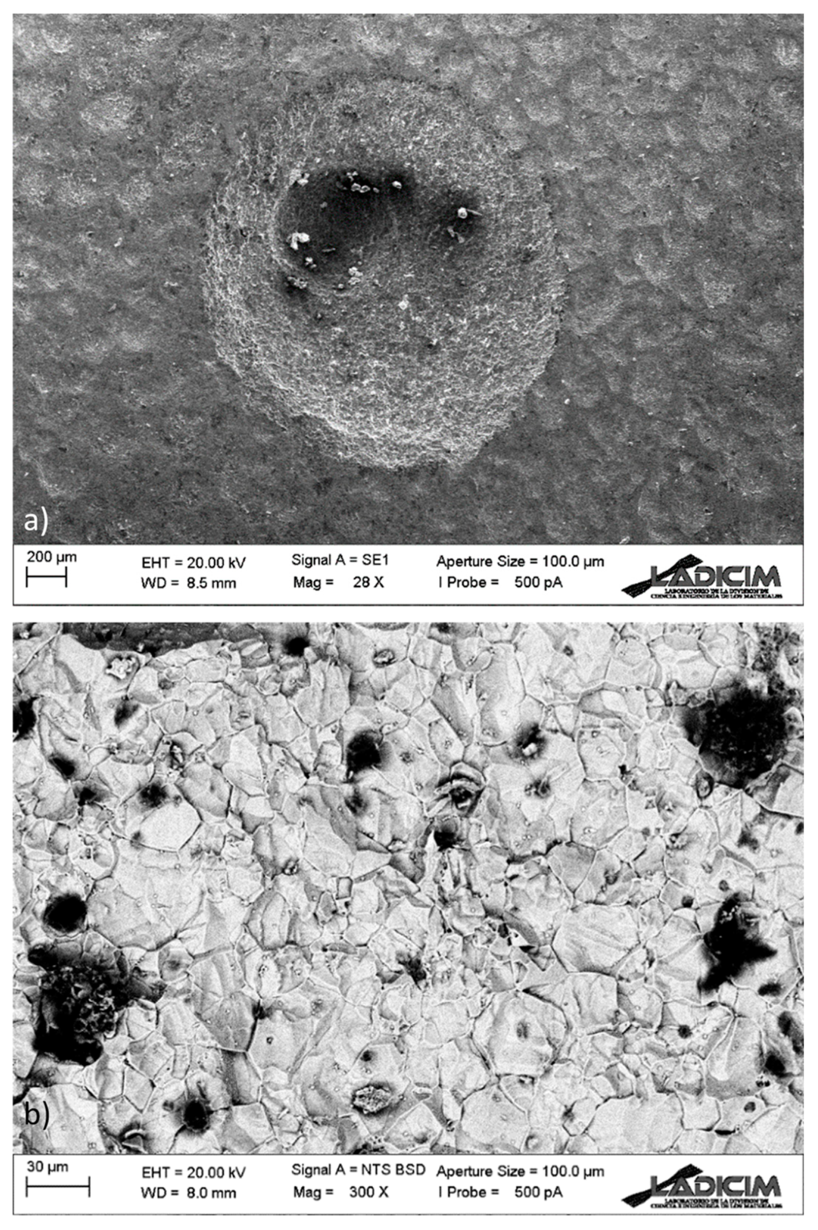
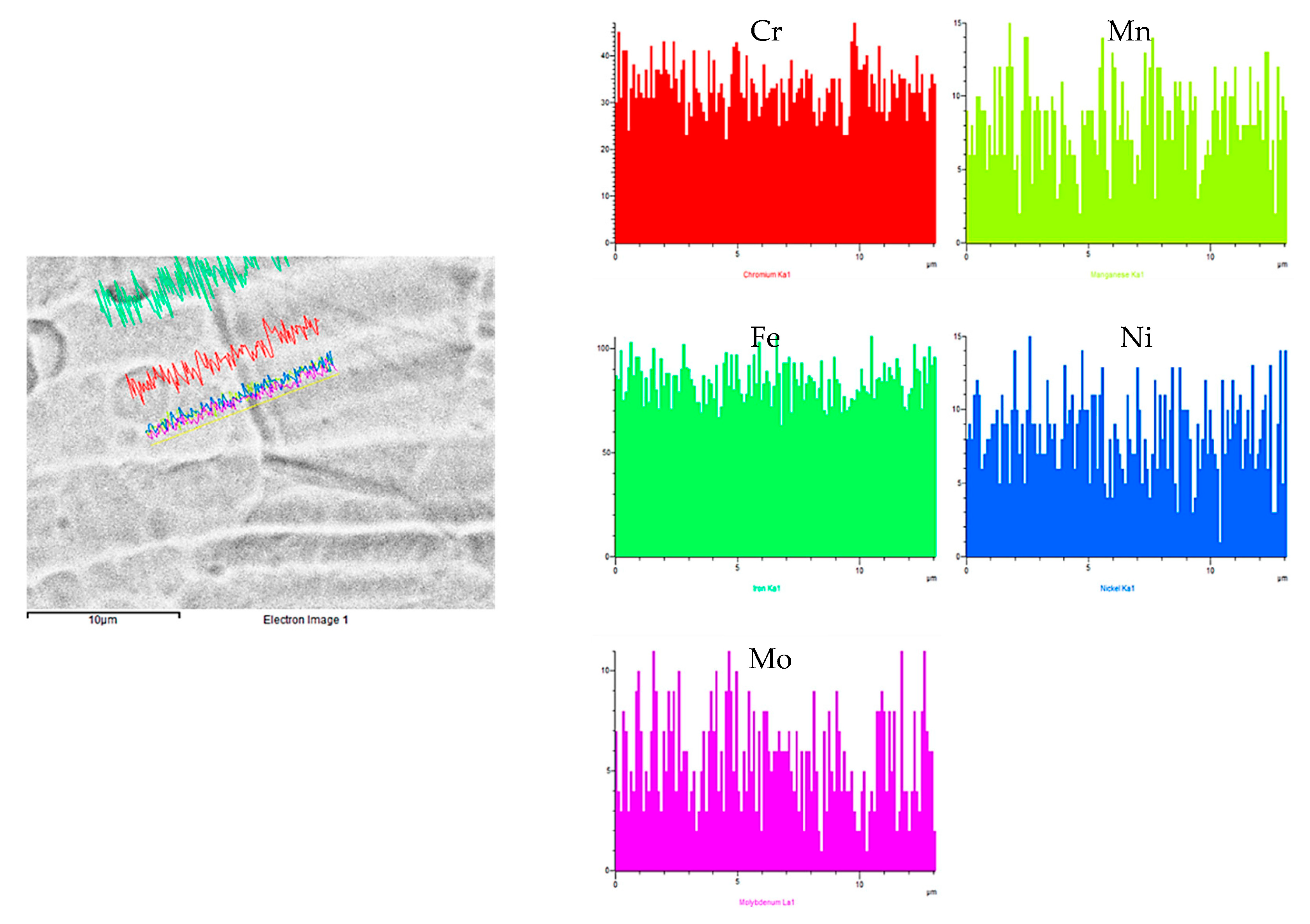
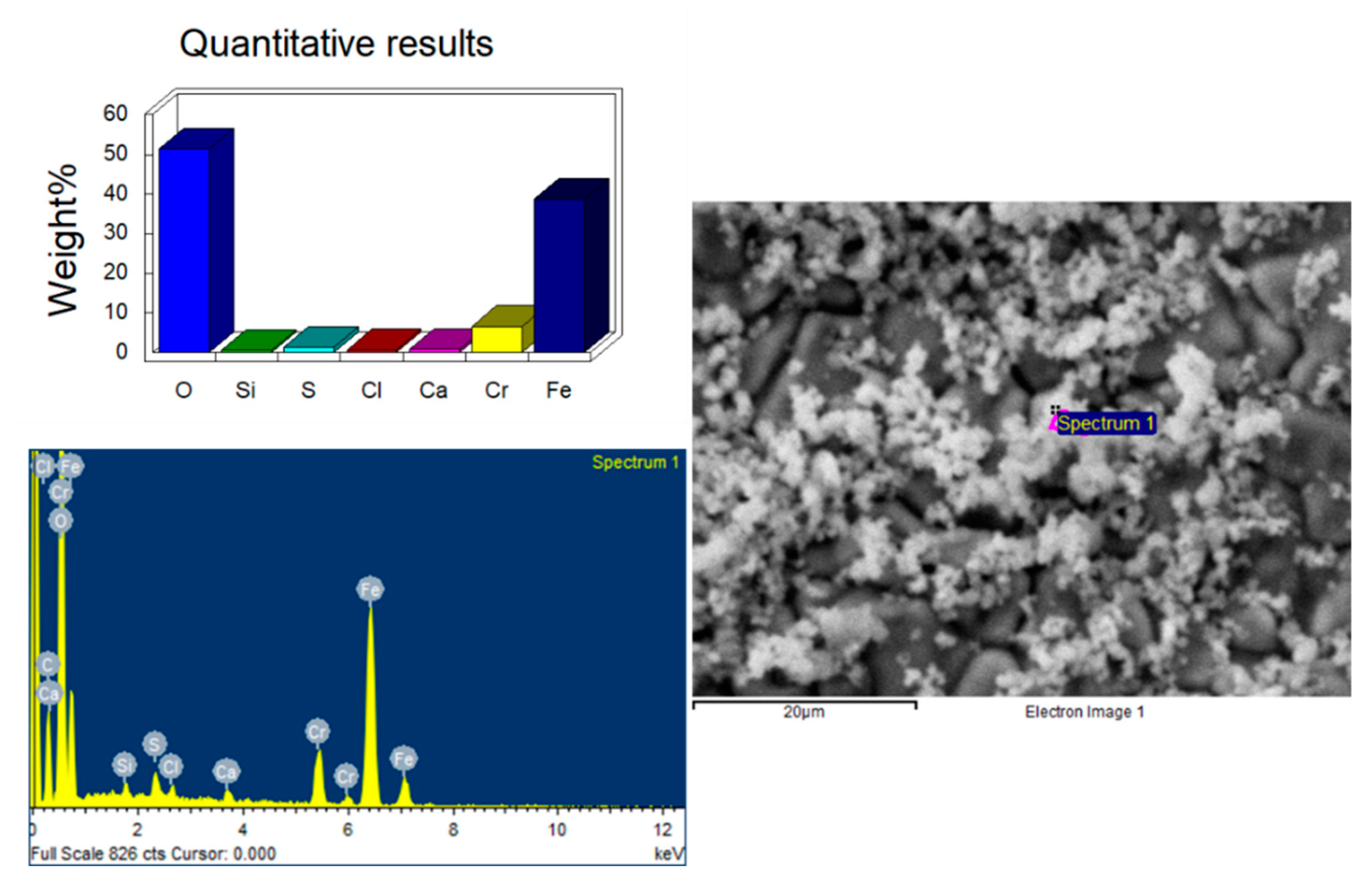
3.4. SEM Analysis of the Pitting Defects

Two sub-samples from the section of the pipe received in the laboratory were obtained in order to carry out a scanning electron microcopy (SEM) analysis of the micromechanisms taking part in the pitting process analyzed here. One sub-sample contained the main trough-wall pitting (Figure 2a) and its surrounding area, and another sample contained an area where generalized pitting in an earlier stage of the process could be observed (Figure 3).
Figure 7a shows an image obtained by means of SEM of the through-wall pitting of the sample (inner face). In this image, the areas in which the process has advanced in depth, connecting with the outer surface, can be clearly distinguished. Additionally, a second region adjacent to the perforations can also be observed (see Figure 7b), where a loss of material was clear to the naked eye. In this region the tube has lost part of the surface material and grain boundaries are noticeable, pointing to a process that advances preferentially along such grain boundaries. Finally, Figure 7c shows an area attached to the through-wall pitting where no metal loss was observed by the naked eye, but where an advanced level of damage at grain boundaries can be seen through the SEM image, supporting the previous observation about the preferential attack at the grain boundaries.
Meanwhile, Figure 8a presents another pitting from the second sub-sample, which is in an earlier stage of the process. It can be observed that it is not a through-wall pitting. In this case, the observation at higher magnification, shown in Figure 8b, makes it possible to once again confirm the existence of the same type of processes that advances preferentially through the grain boundaries.
As a first hypothesis to explain the corrosion processes progressing along the grain boundaries, it is worth considering the existence of chromium carbides precipitates at the grain boundary. However, the low carbon content of grade AISI 316L stainless steel makes the formation of these precipitates very difficult in practice (chemical composition analysis revealed 0.022% C content).
In any case, to rule this out, a semi-quantitative chemical composition scan was carried out using SEM, with an example of the results found being shown in Figure 9 (chemical composition scan in a non-damaged area) and Figure 10 (chemical composition in a particular grain boundary within a damaged area). In all cases, no peaks of Cr were observed. If these analyses had detected abnormally low Cr percentages, they would have been indirectly indicative of chromium carbide precipitation at the grain boundary (the zone close to the precipitates becomes depleted of Cr to feed the carbides). With all this, steel sensitization (precipitation of chromium carbides at the grain boundary) can be ruled out as the main cause of the corrosion phenomena being analyzed.
Finally, a SEM semi-quantitative analysis of the chemical composition of the corrosion products deposited in the sample was carried out in the area presented in Figure 3, where onset pitting and corrosion deposits can be observed. The results, which are presented in Figure 11, show the presence of sulfur (S) in non-negligible percentages, which cannot come from the small amount of sulfur existing in the steel (see Table 1 with a <0.008% S content). Thus, necessarily, sulfur has been provided externally, quite likely by the corrosive agent.

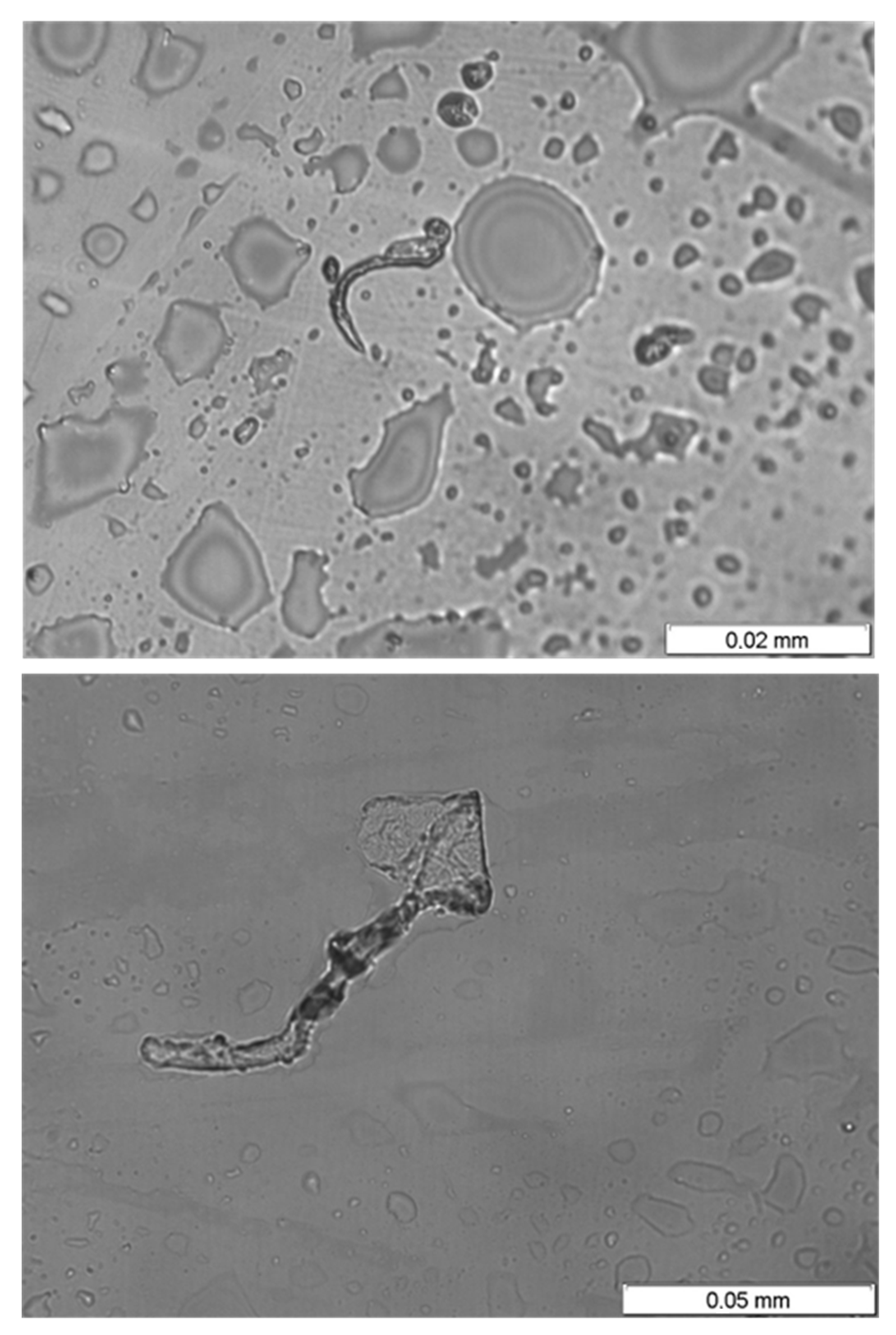
3.5. Bacterial Culture of the Water Found Inside the Piping System

Once the piping system has been studied, the stagnant water found inside was analyzed in order to further assess the corrosion causes. A sample of stagnant water in an area with an abundance of corrosion products, and close to regions with clear evidence of the corrosion processes described above, was obtained.
The sample was analyzed by culturing the mixture of microorganisms present in Kliguer medium and inoculation in a flute beak at 25 °C for 1 week. The results during the observation time did not show the presence of fermenters, but the culture did return a positive result in terms of the presence of sulfate-reducing-bacteria (SRB). This positive in SRB in the culture is observed as a consequence of the reduction of sodium thiosulfate to hydrogen sulfide, and its precipitation as iron sulfide S3Fe2, which generates pockets of H2S, probably corresponding to the gas pockets shown in Figure 6. This hydrogen sulfide can then be used by sulfur chemolithotrophic bacteria, which cannot be detected with the culture medium used in this case, and which oxidizes it, generating the acidification of the medium.
Despite the fact that DNA sequencing is required for the exact determination of the type of SRB bacteria, an observation of the water samples under an optical microscope allowed organisms to be detected that probably correspond to the type of bacteria that proliferated during the culture, as shown in Figure 12.

3.6. Discussion

The main features to highlight in the analyses carried out are:
-
the type of corrosion defects observed, which are mainly pit-type defects,
-
the presence of gas pockets detected in some of the pits,
-
the development of the process in a short time, before the piping system was put into service, and about five months after its construction,
-
the lack of water circulation in this period, as well as the evidence of the existence of stagnant water,
-
the presence of sulfur in the corrosion deposits, as revealed by the SEM semi-quantitative analysis,
-
the presence of sulfate-reducing bacteria (SRB), as revealed by the bacterial culture, and,
-
the absence of other obvious signs of aggressiveness of the environment or defects in the material.
Thus, based on both the morphology of the corrosion damage observed and the evidence of the presence of sulfate reducing bacteria (SRB), microbiologically induced corrosion (MIC) by SRB seems to be the fundamental cause of the process suffered by the pipes being analyzed.
Sulfate-reducing bacteria (SRB) comprise several groups of bacteria that use sulfate (which in this case must be present in the water) as an oxidizing agent, reducing it to hydrogen sulfide H2S, which is a gas with a high corrosive capacity. The process generally takes place under anaerobic conditions, favored by the formation of a sheet of biological material itself (biofilm) or other elements of the system (sludge, coatings, oils). The accumulation of H2S gives rise to the formation of pockets [23], which justify the existence of bubbles and also tubers as the ones observed in Figure 6.
There are many references in the literature reporting failures caused by MIC corrosion in different types of stainless steels [24,25,26,27,28,29] and, in particular, in AISI 316L grade [30,31,32,33,34]. These references share typology, characteristics, and a failure time range with the deterioration process analyzed here.
The analysis performed here also allows different recommendations to be provided in order to avoid similar problems. The main one consists of avoiding the presence of stagnant water in the system, given that this is the final cause of the MIC corrosion process. Additionally, other alternatives, such as the use of inhibitors, could be considered, as it has been successfully applied in other corrosive contexts (e.g., [35,36]).
Finally, when performing this kind of failure analysis where corrosion processes are clearly involved, the use of electrochemical analyses could be considered to clarify the root cause of the failure and the material tendency to develop this kind of damage (e.g., [37,38]).

4. Conclusions

According to the analysis carried out, the following conclusions can be derived:
Corrosion pitting-like defects have been the cause of the failures found in the piping system. Additionally, the development of the corrosion process has been very fast (5 months).
  • The robotic video-inspection confirmed that generalized pitting corrosion with thorough-wall pitting is present in the whole facility to a higher or lower degree. Pockets of gas associated with some of the pits can be observed, while in others “mushroom-shaped” marks show the previous presence of gas bags.
  • The chemical composition of the material fits the requirements of AISI 316L grade stainless steel, so material deficiencies are not the cause of the corrosion processes.
  • There is also evidence (level marks of corrosion products) of the presence of stagnant water (corrosion products characterized by a reddish hue under the level mark). The culture of the remains on the stagnant water samples from the facility has been positive in terms of the presence of sulfate-reducing bacteria (SRB).
  • During the SEM analysis, in the more developed pits, a preferentially radial direction was not observed, as would occur in the case of pitting by chlorides, discarding this type of process; the pits follow an intricate path from the inner face to the outer one. Additionally, it revealed no evidence of sensitization in the steel (roughly constant Cr content in grains and boundaries), but the presence of sulfur was detected in non-negligible quantities in the corrosion products.
Based on this, it can be concluded that the observed process fits within the so-called microbiologically induced corrosion (MIC), and it can be affirmed that this process is promoted by the presence and proliferation of sulfate-reducing bacteria (SRB). On the other hand, no signs of aggressiveness in the environment different from those typical of port areas were found. Finally, the typology of the detected defects is similar to that of other MIC cases reported in the literature, as well as the rest of the characteristics: type of pits, corrosion products, time to failure, etc., supporting the aforementioned conclusion.

Author Contributions

Conceptualization, B.A., R.L. and J.A.Á.; methodology, B.A., R.L., J.A.Á. and S.C.; formal analysis, B.A., R.L., J.A.Á. and S.C.; investigation, B.A., R.L., J.A.Á., S.C. and X.M.-V.; writing—original draft preparation, B.A., R.L., J.A.Á. and S.C.; writing—review and editing, B.A., R.L., J.A.Á., S.C. and X.M.-V. All authors have read and agreed to the published version of the manuscript.

Funding

This research received no external funding.

Institutional Review Board Statement

Not applicable.

Informed Consent Statement

Not applicable.

Data Availability Statement

The data presented in this study are available on request from the corresponding authors.

Conflicts of Interest

The authors declare no conflict of interest.

References

  1. Hu, Y.T.; Dong, P.F.; Jiang, L.; Xiao, K.; Dong, C.F.; Wu, J.S. Corrosion behavior of riveted joints of TC4 Ti-Alloy and 316L Stainless Steel in simulated marine atmosphere. J. Chin. Soc. Corros. Prot. 2020, 40, 167–174. [Google Scholar]
  2. Bazgir, M.; Rahmani, K. Anodic protection of 316L stainless steel piping in sulfuric acid service: Failure causes and remedial actions. Corros. Rev. 2021, 39, 453–464. [Google Scholar] [CrossRef]
  3. Wigen, S.M.; Osvoll, H.; Gartland, P.O.; Huang, W. Efficient cathodic protection of stainless steel small bore tubing. In Proceedings of the CORROSION 2007, Nashville, TN, USA, 11–15 March 2007; pp. 070781–0707814. [Google Scholar]
  4. Kajiyama, F.; Okamura, K. Evaluating cathodic protection reliability on steel pipe in microbially active soils. Corrosion 1999, 55, 74–80. [Google Scholar] [CrossRef]
  5. Tseluikin, V.N. Electrodeposition and properties of composite coatings modified by fullerene C60. Prot. Met. Phys. Chem. Surf. 2017, 53, 433–436. [Google Scholar] [CrossRef]
  6. Tseluikin, V.N.; Koreshkova, A.A. Pulsed electrodeposition of composite coatings based on zinc–nickel alloy. Prot. Met. Phys. Chem. Surf. 2018, 54, 453–456. [Google Scholar] [CrossRef]
  7. Lanzutti, A.; Lekka, M.; de Leitenburg, C.; Fedrizzi, L. Effect of pulse current on wear behaviour of Ni matrix micro- and nano-SiC composite coatings at room and elevated temperature. Tribol. Int. 2019, 132, 50–61. [Google Scholar] [CrossRef]
  8. Stoltenhoff, T.; Kreye, H.; Richter, H.J. An analysis of the cold spray process and its coatings. J. Therm. Spray Technol. 2002, 11, 542–550. [Google Scholar] [CrossRef]
  9. Chiodo, M.S.G.; Ruggieri, C. Failure assessments of corroded pipelines with axial defects using stress-based criteria: Numerical studies and verification analyses. Int. J. Press. Vessel. Pip. 2009, 86, 164–176. [Google Scholar] [CrossRef]
  10. Greenshields, C.J.; Leevers, P.S.; Morris, J. Brittle fracture of plastic water pipes. Pipes Pipelines Int. 1997, 42, 11–16. [Google Scholar]
  11. Schmitt, C.; Pluvinage, G.; Hadj-Taieb, E.; Akid, R. Water pipeline failure due to water hammer effects. Fatigue Fract. Eng. Mater. Struct. 2006, 29, 1075–1082. [Google Scholar] [CrossRef]
  12. Gonzalez, M.; Machado, R.; Gonzalez, J. Fatigue analysis of PE-100 pipe under axial loading. Am. Soc. Mech. Eng. Press. Vessel. Pip. Div. (Publ.) PVP 2011, 6, 905–911. [Google Scholar]
  13. Guedes, R.M.; Sá, A.; Faria, H. On the prediction of long-term creep-failure of GRP pipes in aqueous environment. Polym. Compos. 2010, 31, 1047–1055. [Google Scholar] [CrossRef]
  14. Sadiq, R.; Rajani, B.; Kleiner, Y. Probabilistic risk analysis of corrosion associated failures in cast iron water mains. Reliab. Eng. Syst. Saf. 2004, 86, 1–10. [Google Scholar] [CrossRef] [Green Version]
  15. Abouswa, K.; Elshawesh, F.; Elragei, O.; Elhood, A. Corrosion investigation of Cu-Ni tube desalination plant. Desalination 2007, 205, 140–146. [Google Scholar] [CrossRef]
  16. Xia, Y.; Shi, M.; Zhang, C.; Wang, C.; Sang, X.; Liu, R.; Zhao, P.; An, G.; Fang, H. Analysis of flexural failure mechanism of ultraviolet cured-in-place-pipe materials for buried pipelines rehabilitation based on curing temperature monitoring. Eng. Fail. Anal. 2022, 142, 106763. [Google Scholar] [CrossRef]
  17. Zhang, H.; Li, C.T.; Song, L.J.; Shi, Q.F.; Li, Y. Effects of pH on electrochemical properties of 316L Stainless Steel. Corros. Prot. 2013, 34, 593–596. [Google Scholar]
  18. Wang, J.; Shang, X.C.; Lu, M.X.; Zhang, L. Pitting nucleation of 316L Stainless Steel in different environments. J. Mater. Eng. 2015, 43, 12–18. [Google Scholar]
  19. Liu, B.; Duan, J.Z.; Hou, B.R. Study on corrosion behavior of 316L Stainless Steel by microbial film in seawater. J. Chin. Soc. Corros. Prot. 2012, 32, 48–53. [Google Scholar]
  20. Khandouzi, M.K.; Bahrami, A.; Hosseini-Abari, A.; Khandouzi, M.; Taheri, P. Microbiologically Influenced Corrosion of a pipeline in a petrochemical plant. Metals 2019, 9, 459. [Google Scholar] [CrossRef] [Green Version]
  21. Liu, B.; Sun, M.H.; Lu, F.Y.; Du, C.W.; Li, X.G. Study of biofilm-influenced corrosion on X80 pipeline steel by a nitrate-reducing bacterium, bacillus cereus, in artificial Beijing soil. Colloids Surf. B Biointerfaces 2021, 197, 111356. [Google Scholar] [CrossRef]
  22. A276/A276M-17; Standard Specification for Stainless Steel Bars and Shapes. ASTM International: West Conshohocken, PA, USA, 2021.
  23. Procópio, L. The era of ‘omics’ technologies in the study of microbiologically influenced corrosion. Biotechnol Lett. 2020, 42, 341–356. [Google Scholar] [CrossRef] [PubMed]
  24. Ilhan-Sungur, E.; Cansever, N. Case History 02.15.25.001. In Corrosion Atlas; Elsevier: Amsterdam, The Netherlands, 2019. [Google Scholar]
  25. Hussain, M.; Zhang, T. Case History 02.21.25.002. In Corrosion Atlas; Elsevier: Amsterdam, The Netherlands, 2019. [Google Scholar]
  26. Van der Kolk, F. Micro-Organisms Destroyed Stainless Steel Installation, Maintworld, Vols. 3–4. Available online: https://www.maintworld.com/Applications/Micro-organisms-Destroyed-Stainless-Steel-Installation (accessed on 20 January 2023).
  27. Ress, J.; Monrrabal, G.; Díaz, A.; Pérez-Pérez, J.; Bastidas, J.M.; Bastidas, D.M. Microbiologically influenced corrosion of welded AISI 304 stainless steel pipe in well water. Eng. Fail. Anal. 2020, 116, 104734. [Google Scholar] [CrossRef]
  28. Miller, B.A.; Shipley, R.J.; Parrington, R.J.; Dennies, D.P. (Eds.) ASM Handbook, Volume 11: Failure Analysis and Prevention; ASM International: Materials Park, OH, USA, 2002. [Google Scholar]
  29. Stoecker, J.G. A Practical Manual on Microbiologically Influenced Corrosion; NACE International, The Corrosion Society: Houston, TX, USA, 2001. [Google Scholar]
  30. Otero, E.; Bastidas, J.M.; Lopez, V. Analysis of a premature failure of welded AlSl316L stainless steel pipes originated by microbial induced corrosion. Mater. Corros. 1997, 48, 447–454. [Google Scholar] [CrossRef] [Green Version]
  31. Wu, C.; Wang, Z.; Zhang, Z.; Zhang, B.; Ma, G.; Yao, Q.; Gan, Z.; Wu, J.; Li, X. Influence of crevice width on sulfate-reducing bacteria (SRB)-induced corrosion of stainless steel 316L. Corros. Commun. 2021, 4, 33–44. [Google Scholar] [CrossRef]
  32. Liu, H.; Sharma, M.; Wang, J.; Cheng, Y.F.; Liu, H. Microbiologically influenced corrosion of 316L stainless steel in the presence of Chlorella vulgaris. Int. Biodeterior. Biodegrad. 2018, 129, 209–216. [Google Scholar] [CrossRef]
  33. Xu, C.; Zhang, Y.; Cheng, G.; Zhu, W. Localized corrosion behavior of 316L stainless steel in the presence of sulfate-reducing and iron-oxidizing bacteria. Mater. Sci. Eng. A 2007, 443, 235–241. [Google Scholar] [CrossRef]
  34. Dao, V.H.; Ryu, H.K.; Yoon, K.B. Leak failure at the TP316L welds of a water pipe caused by microbiologically influenced corrosion. Eng. Fail. Anal. 2021, 122, 105244. [Google Scholar] [CrossRef]
  35. Liu, Z.; Fan, B.; Zhao, J.; Yang, B.; Zheng, X. Benzothiazole derivatives-based supramolecular assemblies as efficient corrosion inhibitors for copper in artificial seawater: Formation, interfacial release and protective mechanisms. Corros. Sci. 2023, 212, 110957. [Google Scholar] [CrossRef]
  36. Liu, Y.; Fan, B.; Xu, B.; Yang, B. Ambient-stable polyethyleneimine functionalized Ti3C2Tx nanohybrid corrosion inhibitor for copper in alkaline electrolyte. Mater. Lett. 2023, 337, 133979. [Google Scholar] [CrossRef]
  37. Praveen, B.M.; Alhadhrami, A.; Prasanna, B.M.; Hebbar, N.; Prabhu, R. Anti-corrosion behavior of olmesartan for soft-cast steel in 1 mol dm−3 HCl. Coatings 2021, 11, 965. [Google Scholar] [CrossRef]
  38. Hebbar, N.; Praveen, B.M.; Prasanna, B.M.; Vishwanath, P. Electrochemical and adsorption studies of 4-Chloro, 8-(Trifluoromethyl) Quinoline (CTQ) for mild steel in acidic medium. J. Fail. Anal. Prev. 2020, 20, 1516–1523. [Google Scholar] [CrossRef]
Figure 1. Sample of pipe extracted from the port piping system; a through-wall pitting can be observed in the center (black arrow).
Applsci 13 02598 g001
Figure 2. Through-wall pitting in the sample. (a) Through-wall pitting in the sample, outer face; (b) through-wall pitting and other pitting onsets, inner face of the sample. The arrows indicate the observed pits.
Applsci 13 02598 g002
Figure 3. Multiple pitting onsets on the inside of the tube.
Applsci 13 02598 g003
Figure 4. Area (red ellipse) with deposits of reddish corrosion products; inner face of the tube. The arrow indicates a straight line identified as the level achieved by the stagnant water.
Applsci 13 02598 g004
Figure 5. Video-inspection image of the interior of the piping system. (a) Detail of pitting; (b) detail of “mushroom-shaped” marks around two pits.
Applsci 13 02598 g005
Figure 6. Video-inspection image of the interior of the piping system. (a) Gas bubbles; (b) detail of gas bubbles, right over some pitting defects.
Applsci 13 02598 g006
Figure 7. (a) SEM image of a through-wall pitting on the inner face of the tube sample; (b) surrounding area with metal loss observed by naked eye; (c) surrounding area without metal loss to naked eye.
Applsci 13 02598 g007
Figure 8. (a) SEM image of a pitting in an early stage of the process on the inner face of the sample; (b) detail of the pitting in an early stage.
Applsci 13 02598 g008
Figure 9. Grain boundary semi-quantitative chemical composition scan by means of SEM; Cr in red. Non-damaged area.
Applsci 13 02598 g009
Figure 10. Spot analysis of semi-quantitative chemical composition by means of SEM in damaged grain boundary; Cr content is around 16%.
Applsci 13 02598 g010
Figure 11. Chemical analysis (SEM) of corrosion products in the tube.
Applsci 13 02598 g011
Figure 12. Organisms (probably SRB) observed in the culture.
Applsci 13 02598 g012
Table 1. Chemical composition of the stainless-steel sample (% weight).
TestRequired [22]
C0.022 ± 0.005<0.03
Si0.450 ± 0.072 <1.00
Mn1.507 ± 0.080<2.00
P0.035 ± 0.005<0.045
S<0.008<0.03
Cr16.22 ± 0.4816.0–18.0
Ni9.86 ± 0.3710.0–14.0
N0.037 ± 0.009--
Mo1.944 ± 0.0912.0–3.0
Cu0.319 ± 0.028--
Disclaimer/Publisher’s Note: The statements, opinions and data contained in all publications are solely those of the individual author(s) and contributor(s) and not of MDPI and/or the editor(s). MDPI and/or the editor(s) disclaim responsibility for any injury to people or property resulting from any ideas, methods, instructions or products referred to in the content.

