Article

Experimental Investigation on Single-Phase Immersion Cooling of a Lithium-Ion Pouch-Type Battery under Various Operating Conditions

Department of Mechanical Engineering, Faculty of Engineering and Architecture, Erzincan Binali Yıldırım University, Erzincan 24100, Turkey
Appl. Sci. 2023, 13(5), 2775; https://doi.org/10.3390/app13052775
Submission received: 18 January 2023 / Revised: 12 February 2023 / Accepted: 17 February 2023 / Published: 21 February 2023
(This article belongs to the Topic Applied Heat Transfer)

Abstract

:
The selection of a battery thermal management technique is important to overcoming safety and performance problems by maintaining the temperature of batteries within a desired range. In this study, a LiFePO4 (LFP) pouch-type battery having a capacity of 20 Ah was experimentally cooled with both air and liquid (immersion cooling) techniques. Distilled water was selected as the immersion fluid in the experiments, and the impact of discharge rate (1–4C), immersion ratio (50–100%), and coolant fluid inlet temperature (15–25 °C) on the battery temperature were investigated during the discharge period. The experiments revealed that maximum temperatures were reached at approximately 45 °C and 33 °C for air and distilled water cooling techniques, respectively, at the discharge rate of 4C. The average and maximum battery surface temperatures can be reduced by 28% and 25%, respectively, with the implementation of the liquid immersion technique at the discharge rate of 4C compared to the air technique. Moreover, the experiments demonstrated that the maximum temperature difference could be lowered to 4 °C by means of 100% liquid immersion cooling at the highest discharge rate, where they are approximately 11 °C and 12 °C for air and 50% for immersion cooling, respectively. In addition, it was observed that the coolant fluid inlet temperature has a significant impact on battery temperature for %100 liquid immersion.

1. Introduction

Recently, interest in electric vehicles has been increasing because of their advantages, such as reduced pollution and noise, compared to vehicles having an internal combustion engine. According to the International Energy Agency [1], 6.6 million electric cars were sold in 2021, which corresponds to 9% of the global car market.
Batteries, electric motors and regenerative braking systems can be stated as the main components of all-electric vehicles [2]. Batteries can be considered one of the most important since they are directly related to their cost and range. Among the different battery options, Lithium-ion (Li-ion) ones are used in electric vehicles since they have specifications such as higher energy density, lighter weight, higher cycle life and lower self-discharge rates [3]. The high-power density demand of Li-ion batteries results in higher heat generation due to reaction heat, electrode over-potential heat and Joule heat of internal electrical resistance during both charging and discharging processes [4]. Since the generated heat adversely affects battery performance, it is necessary to remove it from the battery surface. In the literature, the optimum working temperature of Li-ion batteries is suggested in the range of 20 °C to 40 °C, where the temperature difference on the battery surface should be a maximum of 5 °C [5,6].
If the operating temperature of a battery exceeds these ranges, it is possible to encounter some problems related to safety, thermal runaway and capacity losses [7,8,9,10].
The heat generation of Li-ion batteries is generally measured by means of the calorimeter or determined with electrothermal models. In some studies on this subject [11,12,13,14,15,16,17], reversible/irreversible heat sources, internal resistance and entropy coefficient of battery are evaluated, and new calorimeters have been designed to determine heat generation rate for various operating conditions. In order to remove generated heat from the battery, battery thermal management methods are used, and they are classified as air cooling, liquid cooling, phase change material cooling and a combination of them [18]. Among them, air and liquid (water and ethylene glycol) are generally used for cooling batteries. Air cooling systems have advantages such as low cost, easy maintenance, low weight, simple design and no leakage problem, but they have disadvantages such as low thermal performance, higher fan power consumption and noise [19]. The cooling systems working with liquids have advantages such as high thermal performance, high specific heat capacity of the fluid and homogenous temperature distribution. The liquid cooling system can be designed as direct or indirect according to whether or not there is direct contact between the battery and the cooling fluid. In direct cooling, a dielectric liquid having higher thermal conductivity and lower viscosity contacts the battery and higher heat transfer is obtained compared to indirect cooling. Although indirect liquid cooling is preferred to avoid an electrical short circuit and chemical erosion in application [20], one of the direct contact cooling methods, called immersion cooling, can be used for the battery thermal management of electric vehicles. In this method, batteries are immersed in dielectric and non-flammable fluids such as mineral oils, hydrofluoroethers, esters and water/glycol mixtures, and the heat transfer mechanism can be one- or two-phase flow depending on the fluid’s physical properties. The use of this method significantly enhances heat transfer between fluid and battery and leads to a lower surface temperature and a lower temperature difference compared to indirect liquid and air cooling techniques. Moreover, the risk of thermal runaway can be reduced with the application of immersion cooling [21].
Although immersion cooling was discovered a long time ago [22], it has recently been used in data servers [23,24,25,26] and electronic equipment [27,28,29,30]. The immersion cooling of Li-ion batteries can be considered an emerging subject; thus, there is a limited number of studies on this subject. In studies on the immersion cooling of Li-ion batteries, the performance of immersion cooling is evaluated by comparing temperature results with other methods (such as indirect or air cooling). The experiments and numerical studies are performed using dielectric fluids or mineral oils under the same operating conditions, and the results are compared to distinguish the importance of immersion cooling.
The immersion cooling of cylindrical batteries has been studied by different researchers [31,32,33,34,35,36,37]. Gils et al. [31] performed experiments using Novec 7000 during pool boiling conditions and concluded that immersion cooling has superior thermal performance compared to air cooling. Wang and Wu [32] constructed a battery module with 60 cells and performed flow boiling experiments with HFE-7000. The results revealed that the maximum temperature and difference are approximately 38 °C and 4 °C, respectively, for a 5C discharge rate. Dubey et al. [33] numerically compared the performance of battery modules cooled with cold plate and immersion (Novec 7500) techniques. The researchers stated that the removal of heat from cells could be increased by approximately 32% at the discharge rate of 3C with immersion. Luo et al. [34] experimentally and numerically investigated the heat rejection performance of batteries and revealed that flow rate has a significant impact on temperature. They also stated that the maximum temperature could be kept under 50 °C by using a low mass flow rate where it is necessary to increase the flow rate to obtain lower temperature differences. Jithin and Rajesh [35] compared the thermal performance of three different dielectrics and air regarding temperature variation and pressure loss. They observed that the battery temperature increment could be kept at 2.2 °C during 3C, which is a very low value compared to other fluids tested. Trimbake et al. [36] conducted experiments to cool batteries, and they stated that the temperature increments of batteries working with mineral oil are 4.4 °C and 5.4 °C with the application of free and submerged jets, respectively. Li et al. [37] performed immersion cooling experiments with SF33 fluid and air to investigate the temperature variation for various discharge rates and revealed that the temperature increment of batteries working with SF33 fluid and forced air are approximately 5 °C and 14 °C, respectively.
As another geometric type, the immersion cooling performances of pouch/prismatic-type batteries have been performed by [38,39,40,41,42,43,44,45,46,47,48] in the literature. Chen et al. [38] experimentally and numerically compared the cooling performance of various methods to investigate their effectiveness. Both jacket and oil cooling can be good solutions for the battery temperature rise problem. Hirano et al. [39] performed boiling experiments by submerging batteries into hydrofluoroether fluid and adding porous surfaces between pouch-type batteries to enhance heat transfer. They stated that the temperature of batteries could be kept under 40 °C, which is the upper limit in the desired temperature operating range. Chen and Li [40] conducted experiments to research the immersion cooling of batteries submerged in water/ethylene glycol and evaluated the performance by comparing air results. They concluded that the average and maximum temperatures could be significantly decreased with the implementation of immersion cooling. Sundin and Sponholtz [41] immersed a prismatic battery into AmpCool AC-100 dielectric liquid and showed that the average battery temperature is reduced by approximately 6 °C with the immersion method, and the temperature fluctuations of the battery cooled with dielectric liquid are less than those cooled with air. Larranaga-Ezeiza et al. [42] presented that the average and maximum temperatures can be decreased to 6.5 °C and 9.1 °C with the use of direct and indirect cooling techniques, respectively. Patil et al. [43] experimentally and numerically investigated the cooling of pouch-type Li-ion batteries and revealed that the highest temperature at the positive tab could be decreased by 46% with the application of immersion cooling instead of natural convection. Zhou et al. [44] constructed a battery pack and showed that the temperature of the batteries could be kept at approximately 47 °C as the maximum value in the considered operating ranges. Wang et al. [45] reported that the maximum temperature and temperature difference of batteries could be decreased by 13.4 °C and 3.54 °C, respectively, with the use of transformer oil instead of air. Moreover, the experiments showed that coolant flow rate does not have a significant impact on battery temperature difference under the considered operating conditions. Bhattacharjee et al. [46] showed that the battery temperatures are approximately 35 °C and 31 °C for air and liquid velocities of 10 m/s and 0.01 m/s, respectively, for a discharge rate of 2C. In addition, these results were compared with immersion results, and it was concluded that the immersion method performed the best cooling since the battery temperature is approximately 28 °C. Zhou et al. [47] researched the temperature distribution of pouch-type Li-ion batteries with the immersion cooling method by using dimethyl silicone oil and compared the results with natural air cooling. They stated that the specific heat and flow rate have a significant effect on battery temperature compared to the thermal conductivity of the fluid. Li et al. [48] clarified that the battery temperature could not be kept in desired value range with the application of indirect and air cooling methods at high discharge rates such as 10C, so it is necessary to use a direct cooling method. As a result of the study, they stated that the immersion of batteries into FC-72 and HFE-7100 fluids could be a solution for battery thermal management systems.
Recent growth in the use of electric vehicles has brought up an issue with battery temperature management since the temperature of batteries affects electric vehicles’ range and lifespan of batteries. Although indirect liquid cooling methods have been generally used for solving problems about this issue in applications, it is well known that the direct liquid cooling (immersion) method presents higher heat transfer performance compared to the indirect method. It can be understood from the literature survey that the immersion method can be a good option for battery thermal management systems. In the literature, there is a limited number of research on immersion cooling of prismatic Li-ion batteries and heat transfer oils and hydrofluoroethers are selected as working fluids. In this study, an experimental investigation has been conducted to present the effect of immersion cooling on the temperature distribution of the LiFePO4 (LFP) pouch-type battery. Firstly, natural air convection tests were performed, and then immersion cooling experiments were conducted by using distilled water as the fluid because of its higher specific capacity. The experiments were conducted for various discharge rates (1–4C), immersion ratios (50–100%) and coolant fluid inlet temperatures (15–25 °C). The variation of average and maximum surface temperatures with a depth of discharge/time was researched for considered operating conditions. In addition, maximum temperature differences were determined at the end of the discharges. Although studies on immersion cooling with dielectric water have been presented in the literature for electronic equipment applications, experimental studies on pouch-type batteries cooled with di-electric water are so limited. Because of this reason, it is expected that this study will fill the gap on this issue.

2. Experimental Setup and Procedure

An experimental setup was established in order to investigate the temperature distribution of Li-ion batteries discharging in air and distilled water for both 50% and 100% immersion ratios. It should be noted that heat transfer between fluids and battery can be considered natural convection since neither a circulation fan nor pump was used in the test box. In the experiments, a LiFePO4 battery with a nominal capacity of 20 Ah was used, and its parameters are given in Table 1.
Firstly, ten T-type thermocouples are attached to one side of the battery (T1, T2, T3, T4 and T5) and the other side of the battery (T6, T7, T8, T9 and T10) for temperature measurements, and they are attached to the battery tabs. Besides thermocouples and charge/discharge cables, serpentine copper tubes, water inlet and outlet pipes are mounted to cover the test section. Then, charge/discharge cables are attached to battery tabs, as shown in Figure 1a. After connecting them, the battery is mounted to a test box with a plexiglass case supported by thick sheet metal, and it is insulated with EPS foam to avoid heat transfer between the test box and the environment. It should be noted that plexiglass material is used to determine the level of immersion. The photo of the test box during insulation can be seen in Figure 1b.
The schematic representation and photo of the established experimental setup can be seen in Figure 2a,b, respectively. The red/blue, black and brown lines in Figure 2a show water coolant circuit, connection cables and thermocouple wires, respectively. It should be noted that the inside temperature of the test section is also measured by means of T-type thermocouples, and inlet and outlet temperatures of water are measured by using Pt100 sensors. All thermocouples and Pt100 sensors are connected to the data acquisition system. The temperature measurement devices were calibrated in a water bath using a reference temperature sensor. In addition, a serpentine copper tube is added to the test section to condition it. Moreover, the test section is insulated with insulation material in order to avoid heat transfer between the test section and the ambient. The water coolant circuit is established by using a water bath (chiller), turbine-type flow meter, pump and Pt100 sensors to obtain constant coolant water inlet temperature. It is a closed loop, and the desired inlet temperature of cooling water is adjusted by means of a water bath. Uncertainties for measured parameters are given in Table 2. In all experiments, initial temperatures of air, distilled water and battery surface are 25 °C and at atmospheric pressure.
The working principle of the experimental setup is summarized as follows:
  • Before each experiment, the battery is charged using an electronic power supply at 3.65 V under constant current and constant voltage (CC/CV) mode.
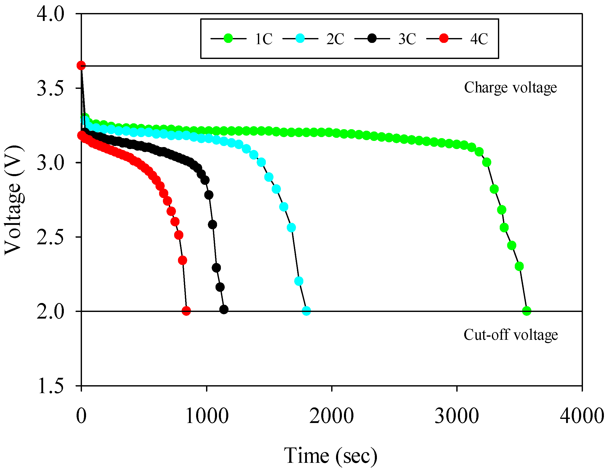
  • The experiments are started by discharging the battery at a desired charge (1C, 2C, 3C and 4C) rate by using an electronic load; the voltage and current values of the battery are recorded during the experiment.
  • Then, the cooling water is circulated by means of a frequency-controlled water circulation pump, and its temperature is measured with a data acquisition system at the inlet of the test section.
  • After the test section, its temperature is measured again with the data acquisition system, and it is directed to the water bath. The cooling water, which is conditioned by using a water bath, is directed to a flowmeter for flow rate measurement.
  • During the experiments, the temperature measurements are recorded by means of a data acquisition system every 10 s.
  • The arithmetic mean and the highest and the lowest values of the thermocouple measurements are determined as the average, maximum and minimum temperatures, respectively.
  • Each experiment ends when the voltage is 2 V which is called cut-off voltage. It is known that the lower values of this voltage lead to capacity reduction problems.

3. Results and Discussion

The variation of voltage during discharge rates of 1C–4C is represented in Figure 3. It should be noted that all discharge rates end at the cut-off voltage corresponding to 2 V. Figure 3 depicts that both the nominal voltage and discharge time values diminish with increasing discharge rate. It can be understood from the figure that the operation voltage has a sharp decrease with the increment of current. Battery discharge durations are recorded as 3550, 1750, 1140 and 840 s for 1C, 2C, 3C and 4C, respectively.
Figure 4 shows the effect of fluid type and immersion ratio on average battery surface temperature for various discharge rates, the cooling water temperature of 25 °C and flow rate of 1 L/min. The average battery surface temperature is determined by the estimation of the arithmetic mean of the ten temperatures. The results revealed that the average battery temperature rises during discharge, and this situation can be explained by an exothermic chemical reaction. The results showed that the average battery surface temperature could be kept in the desired temperature range (between 20 °C and 40 °C) with the use of distilled water for both 50% and 100% immersion. The air cooling is not sufficient, especially for 4C discharge rate. The highest average battery surface temperatures are 32 °C, 35.94 °C and 42.91 °C for 100% water immersion, 50% water immersion and air at the end of 4C discharge rate, respectively. The lowest average battery temperature result was obtained with the application of 100% water immersion because of the higher heat transfer performance of distilled water compared to air. The average battery surface temperature reduces by 13%, 19%, 28% and 25% with the applications of 100% water immersion compared to air for 1C, 2C, 3C and 4C, respectively. In addition, it can be seen that there is a sharp increase in average battery temperatures with higher discharge rates.
Figure 5 demonstrates the variation of maximum battery surface temperatures with the depth of discharge for different fluid types, immersion ratios and various discharge rates, respectively. It can be revealed that there is nonhomogeneous temperature distribution on the battery surface during discharge, and it rises with an increment of discharge rate. According to Figure 5, the maximum battery surface temperatures are 33.32 °C, 42.28 °C and 45.61 °C for 100% water immersion, 50% water immersion and air at the end of 4C discharge rate, respectively. The maximum battery surface temperatures are observed for the positions of T1, T2 and T1 for 100% water immersion, 50% water immersion and air at the end of discharge. It should be noted that the maximum temperatures are observed in the location near the tabs. It can be concluded that the 100% immersion technique can keep battery temperature in the desired range for all considered discharge rates, whereas the other techniques are only appropriate for lower discharge rates (1–2C). Temperature curves depict that the maximum temperature of the battery is significantly affected by immersion since half of the test section is filled with distilled water. Moreover, this situation can also be observed at the minimum temperatures, and the results are given in Table 3.
Figure 6 depicts the effect of discharge rate on average battery surface temperature for air, 50% immersion and 100% immersion. As expected, the average temperature rises with the elevation of discharge rate and time for all cases. Furthermore, the highest temperature results are obtained for air cooling because of the lower specific heat capacity of air, whereas the lowest ones observe for water cooling. The average battery surface temperature is augmented by 38%, 26% and 18% with the increment of discharge rate between 1C and 4C for air cooling, 50% immersion and 100% immersion cooling at the end of discharge, respectively. The increment of temperature at higher discharge rates can be explained by an increased exothermic chemical reaction rate occurring in the battery.
Figure 7 represents the effect of coolant inlet temperature on the average surface temperature of batteries for various discharge rates. The comparison for air cooling results is given in Figure 7a, and it can be concluded that inlet coolant temperature has no significant effect on average battery temperatures working in an air medium. Because of the low specific heat capacity of air, it is difficult to condition working fluid efficiently. The results for 50% immersion cooling experiments show that average surface temperatures are slightly lowered with the reduction of cooling water inlet temperature, as seen in Figure 7b. Because of direct contact between distilled water and the cooling tube, the decrease in average temperature can be significantly observed in the 100% immersion experiments. For all discharge rates, the average temperature gradually increases for the coolant temperature of 25 °C, but the temperature curves are different for the coolant temperature of 15 °C. Figure 7c demonstrates that the average temperature of the battery initially decreases and then increases at the discharge rate of 1C. It takes the lower value of 20.5 °C and rises to 21.2 °C at the end of discharge. In addition, the average temperature of the battery initially decreases to 23.3 °C and 24 °C and then increases up to 24.1 °C and 25.11 °C for 2C and 3C, respectively.
Since the increment of heat is produced by the battery, the battery temperature linearly increases with the depth of discharge up to 29.6 °C at the end of discharge for 4C and 100% immersion. As a result, the coolant inlet temperature has a significant impact on the average battery temperature for 100% immersion.
Figure 8a,b depicts the maximum temperature differences with the application of air, 50% immersion 100% immersion cooling for different discharge rates and coolant water inlet temperatures, respectively. Both figures show that the maximum temperature difference of the battery working in 100% immersion is under 5 °C, which is the desired value for battery performance. In addition, air and 50% immersion cooling are adequate at the discharge rates of 1C and 2C since they are lower than 5 °C; however, it is obvious that it is difficult to keep the maximum temperature difference in desired value for 3C and 4C. This result shows that 50% immersion shows the highest maximum temperature gradients, which will potentially accelerate the degradation and limit the performance of the cells when cells are discharged at high C-rates. Such a case may happen due to leakage or evaporation of coolant in real applications and should be actively monitored.

4. Conclusions

In this research, the effect of the immersion ratio on operation parameters of a pouch-type battery is experimentally investigated using air and distilled water as working fluids. The surface temperature variations of the battery were determined for different discharge rates, immersion ratios and coolant fluid inlet temperature for distilled water. The results are compared with air natural convection results to reveal the impact of immersion cooling. The main findings of this research can be stated as follows:
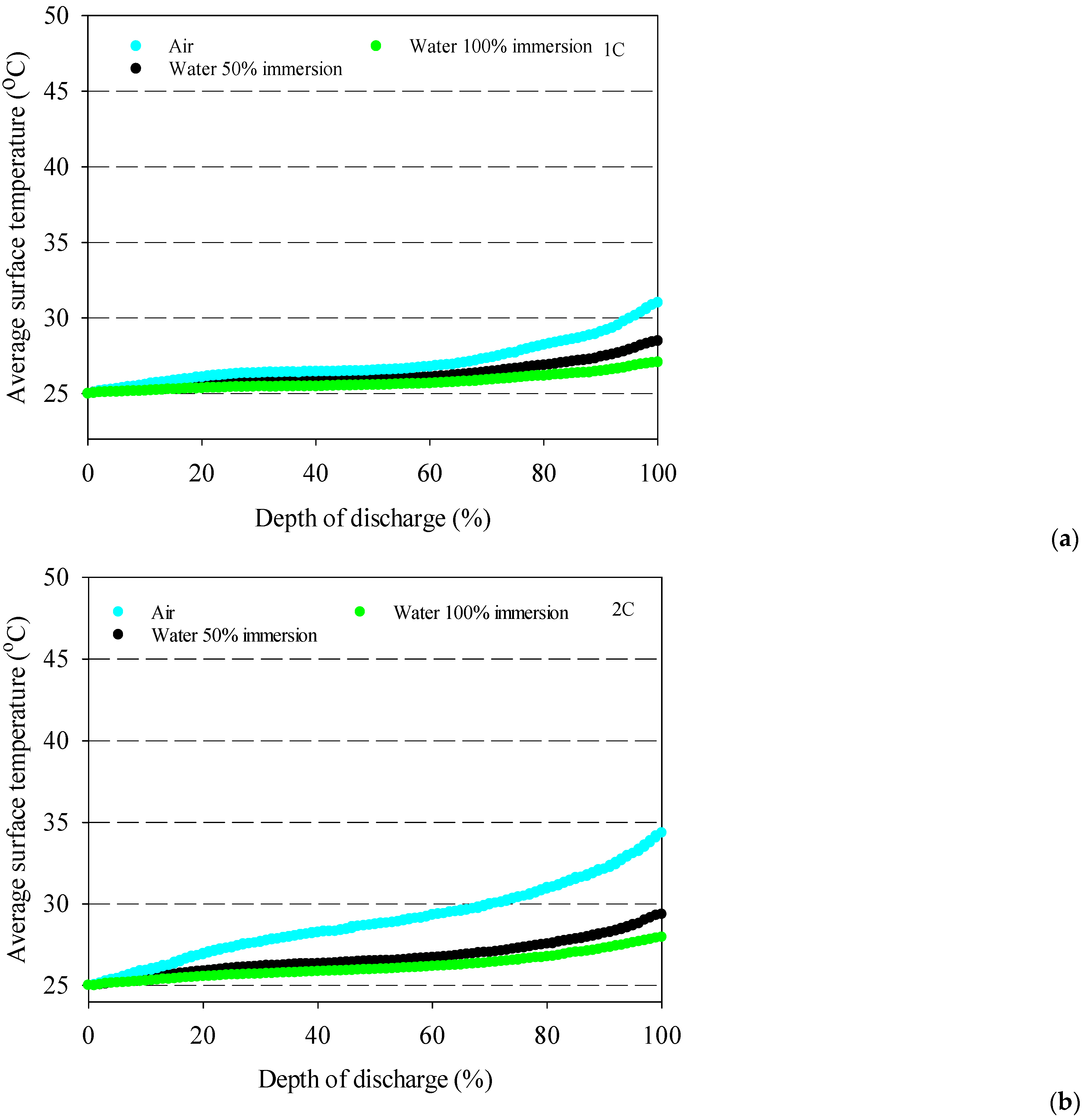
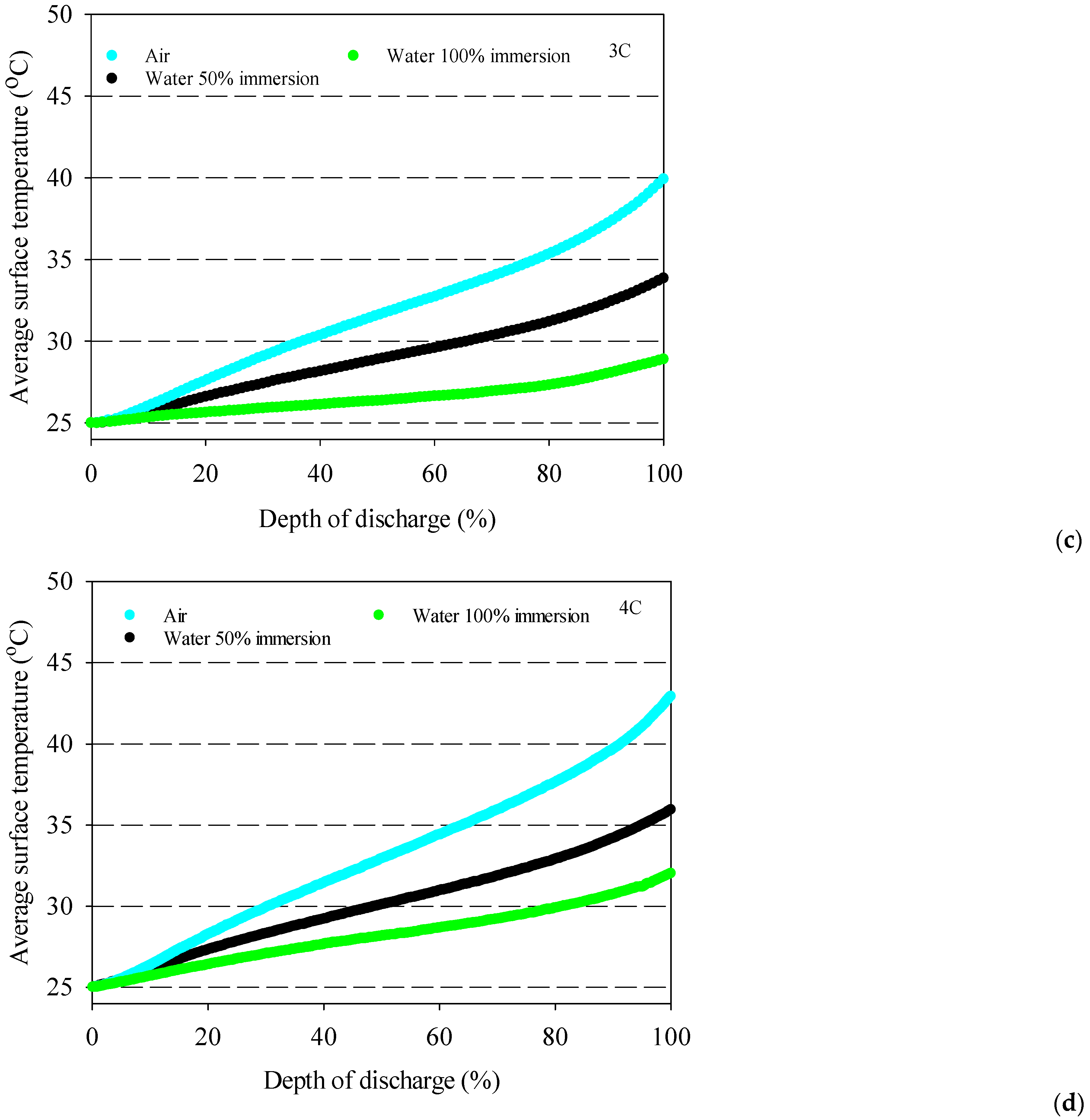
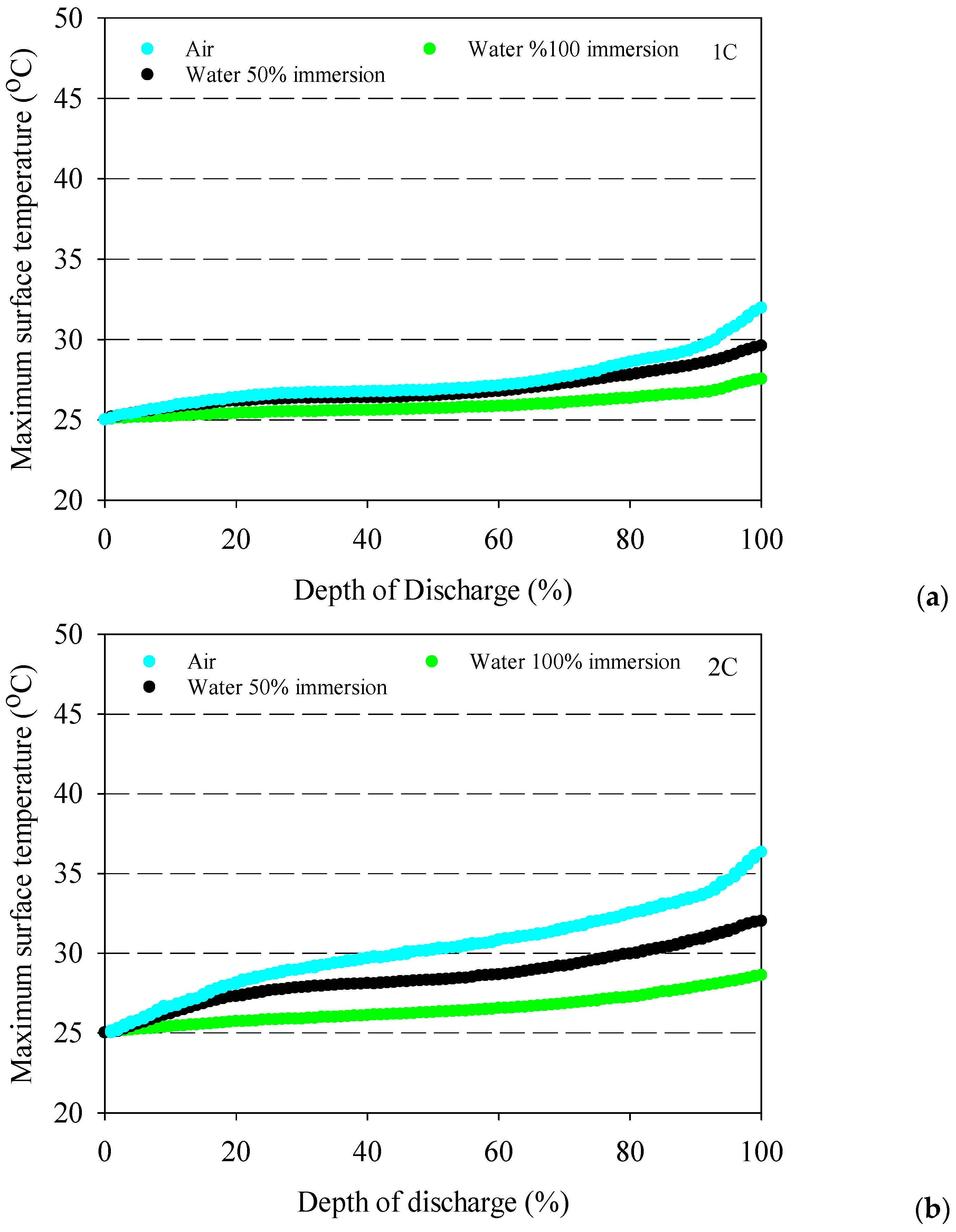
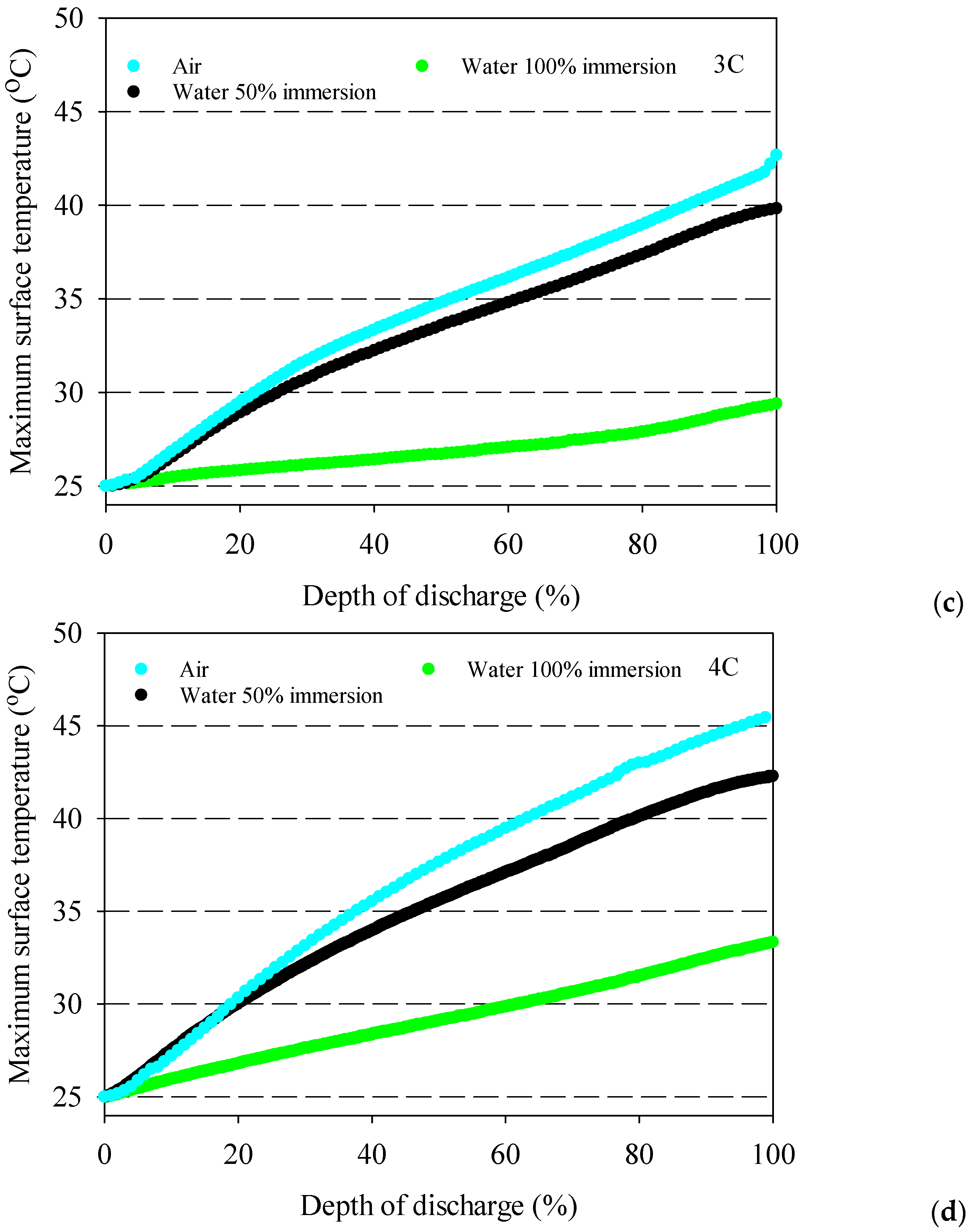
  • The battery surface temperatures increase with an increment of discharge rates for both air and distilled water cooling conditions because of the exothermic chemical reaction occurring in the battery.
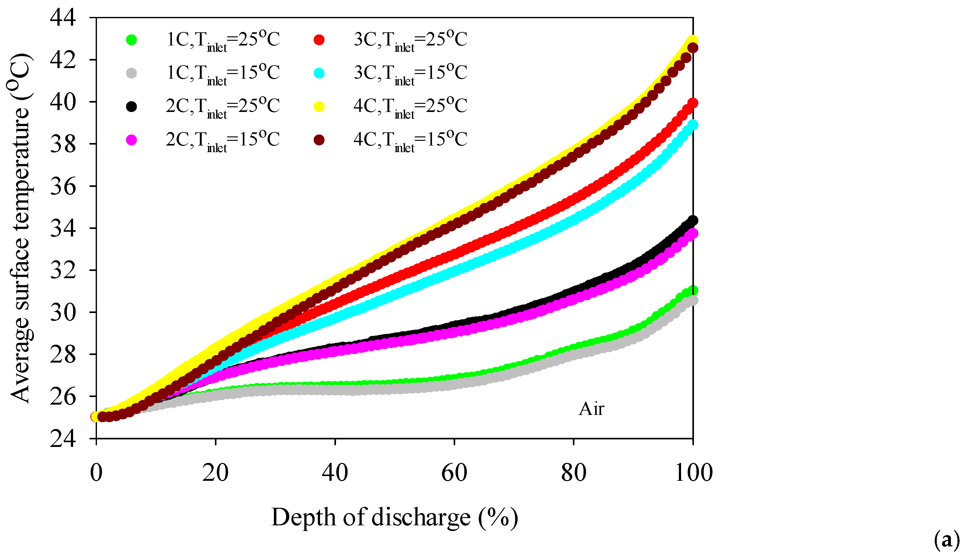
  • The highest average battery surface temperature is observed for air cooling experiments due to the low specific heat capacity of air. This situation is valid for all discharge rates, and the highest increment average battery surface temperature is obtained at 10.9 °C for air at the 4C discharge rate compared to 100% water immersion.
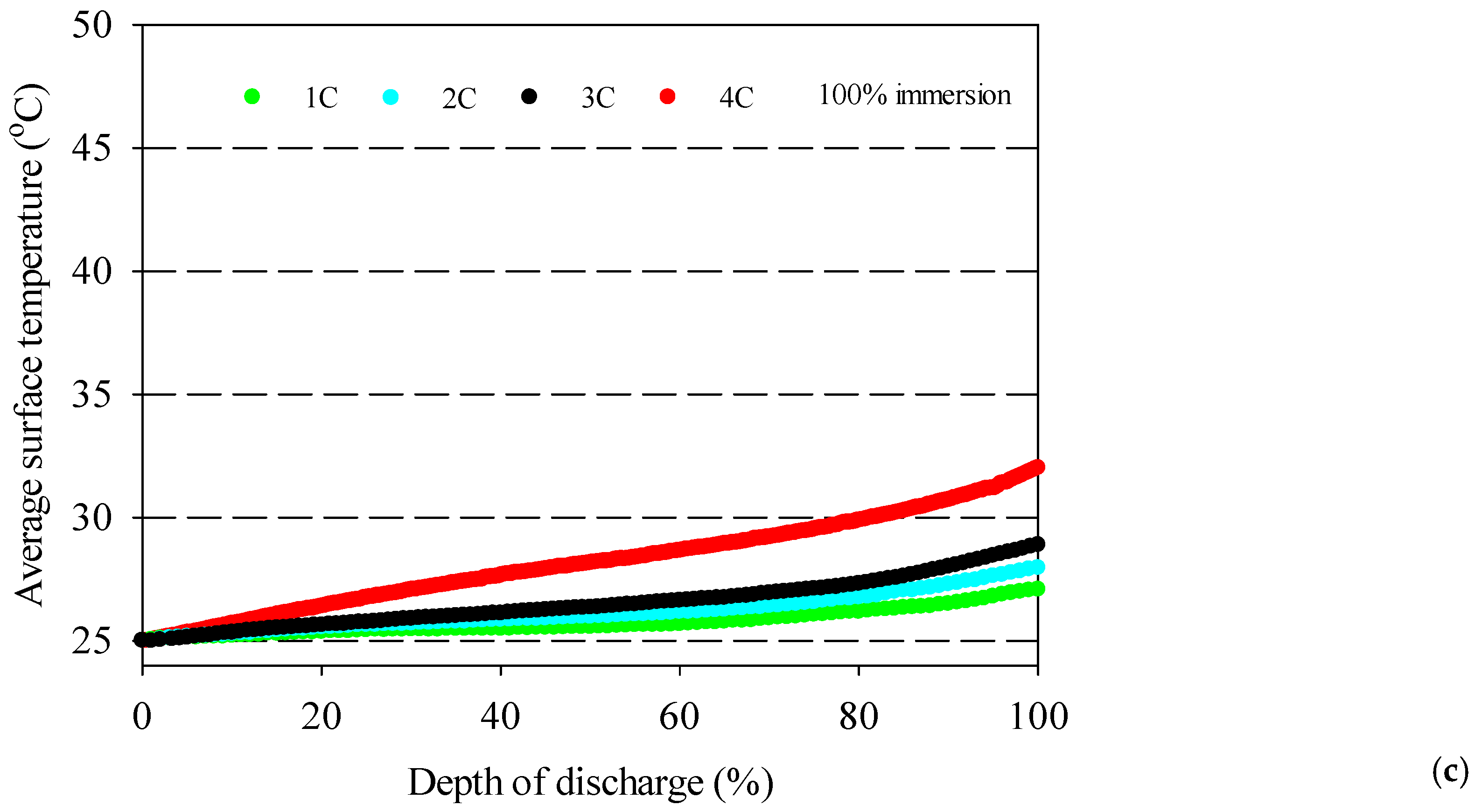
  • 100% immersion cooling has a significant impact on battery surface temperature since it can reduce average battery temperatures by up to 28% for tested working conditions.
  • The lowest battery average surface temperature is recorded with the application of 100% distilled water immersion because of direct contact with fluid, and it increases by approximately 5 °C for different discharge rates in the range between 1–4C.
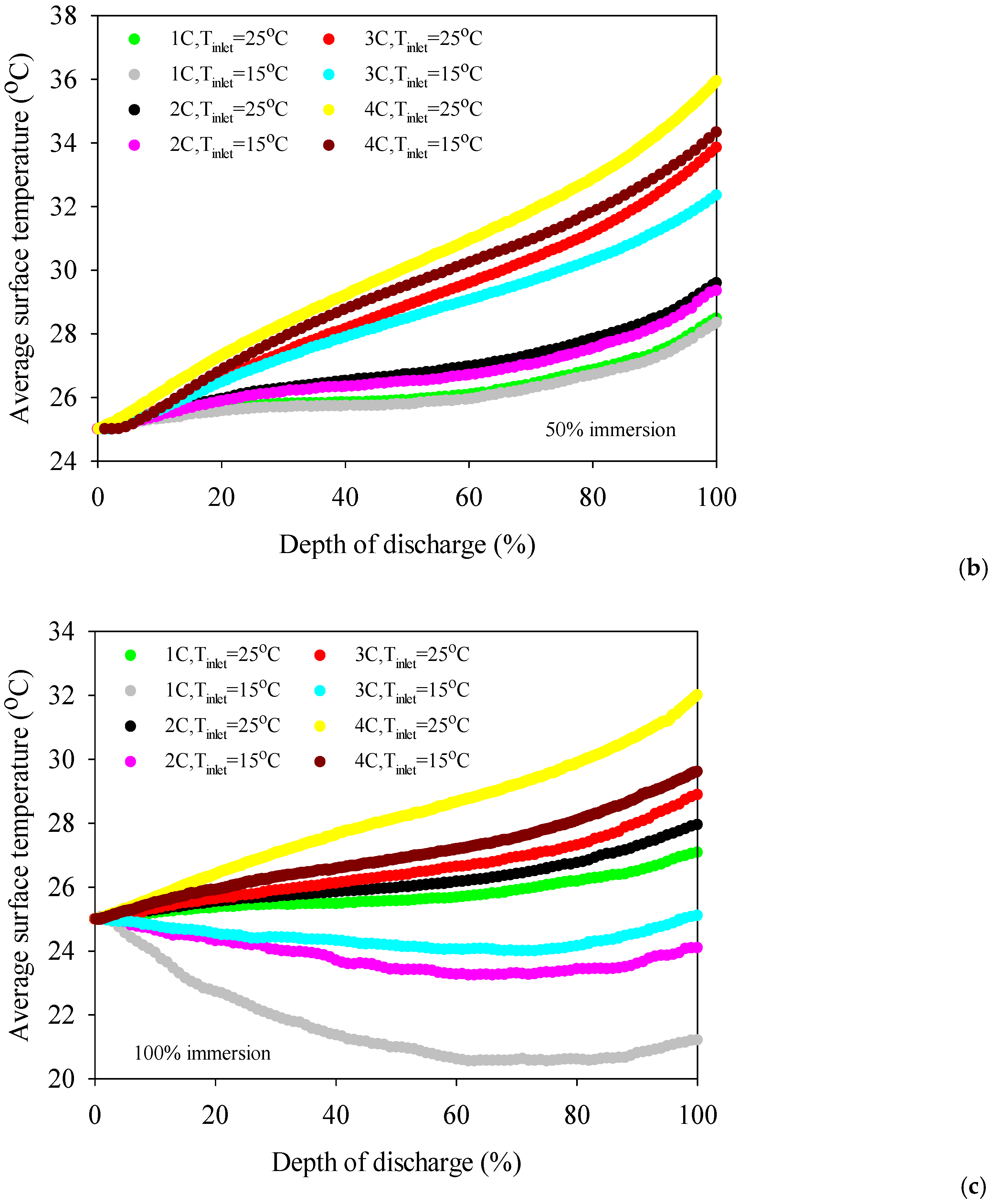
  • The 50% immersion ratio has no significant effect on minimum battery temperature compared to 100%one for all discharge rates.
  • The coolant inlet temperature has no significant impact on battery surface temperature except 100% immersion.
  • The maximum temperature differences can be significantly reduced with the application of immersion cooling.
  • The experimental results revealed that immersion cooling could be a good solution for battery thermal management systems, and their performance can be improved by using dielectric fluid having higher specific heat capacity and thermal conductivity.

Funding

This research received no external funding.

Data Availability Statement

The data presented in this study are available on request from the corresponding author.

Conflicts of Interest

The authors declare no conflict of interest.

References

  1. International Energy Agency. Electric Cars Fend Off Supply Challenges to More Than Double Global Sales. Available online: https://www.iea.org/commentaries/electric-cars-fend-off-supply-challenges-to-more-than-double-global-sales (accessed on 28 December 2022).
  2. Dinçer, I.; Hamut, H.S.; Javani, N. Thermal Management of Electric Vehicle Battery Systems, 1st ed.; John Wiley & Sons: West Sussex, UK, 2016; pp. 6–7. [Google Scholar]
  3. Kim, J.; Oh, J.; Lee, H. Review on battery thermal management system for electric vehicles. Appl. Therm. Eng. 2019, 149, 192–212. [Google Scholar] [CrossRef]
  4. Zhao, G.; Wang, X.; Negnevitsky, M.; Zhang, H. A Review of air-cooling battery thermal management systems for electric and hybrid electric vehicles. J. Power Sources 2021, 501, 230001. [Google Scholar] [CrossRef]
  5. Wang, Q.; Jiang, B.; Li, B.; Yan, Y. A critical review of thermal management models and solutions of lithium-ion batteries for the development of pure electric vehicles. Renew. Sustain. Energy Rev. 2016, 64, 106–128. [Google Scholar] [CrossRef]
  6. Lu, M.; Zhang, X.; Ji, J.; Xu, X.; Zhang, Y. Research progress on power battery cooling technology for electric vehicles. J. Energy Storage 2020, 27, 101155. [Google Scholar] [CrossRef]
  7. Ouyang, D.; Weng, J.; Chen, M.; Wang, J. Impact of high-temperature environment on the optimal cycle rate of lithium-ion battery. J. Energy Storage 2020, 28, 101242. [Google Scholar] [CrossRef]
  8. Xu, B.; Lee, J.; Kwon, D.; Kong, L.; Pecht, M. Mitigation strategies for li-ion battery thermal runaway: A review. Renew. Sustain. Energy Rev. 2021, 150, 111437. [Google Scholar] [CrossRef]
  9. Situ, W.; Yang, X.; Li, X.; Zhang, G.; Rao, M.; Wei, C.; Huang, Z. Effect of high temperature environment on the performance of Lini0.5Co0.2Mn0.3O2 Battery. Int. J. Heat Mass Transf. 2017, 104, 743–748. [Google Scholar] [CrossRef]
  10. Widyantara, R.D.; Zulaikah, S.; Juangsa, F.B.; Budiman, B.A.; Aziz, M. Review on battery packing design strategies for superior thermal management in electric vehicles. Batteries 2022, 8, 287. [Google Scholar] [CrossRef]
  11. Hu, Y.; Choe, S.Y.; Garrick, T.R. Measurement of heat generation rate and heat sources of pouch type Li-ion cells. Appl. Therm. Eng. 2021, 189, 116709. [Google Scholar] [CrossRef]
  12. Hu, Y.; Choe, S.Y.; Garrick, T.R. Measurement of two-dimensional heat generation rate of pouch type lithium-ion battery using a multifunctional calorimeter. J. Power Sources 2022, 532, 231350. [Google Scholar] [CrossRef]
  13. Lin, C.; Xu, S.; Liu, J. Measurement of heat generation in a 40 Ah LiFePO4 prismatic battery using accelerating rate calorimetry. Int. J. Hydrogen Energy 2018, 43, 8375–8384. [Google Scholar] [CrossRef]
  14. Sheng, L.; Su, L.; Zhang, H.; Fang, Y.; Xu, H.; Ye, W. An improved calorimetric method for characterizations of the specific heat and the heat generation rate in a prismatic lithium ion battery cell. Energy Convers. Manag. 2019, 180, 724–732. [Google Scholar] [CrossRef]
  15. Yin, Y.; Zheng, Z.; Choe, S.Y. Design of a calorimeter for measurement of heat generation rate of lithium ion battery using thermoelectric device. SAE Int. J. Altern. Powertrains 2017, 6, 252–260. [Google Scholar] [CrossRef]
  16. Hu, X.; Liu, W.; Lin, X.; Xie, Y.; Foley, A.M.; Hu, L. A control-oriented electrothermal model for pouch-type electric vehicle batteries. IEEE Trans. Power Electron. 2021, 36, 5530–5544. [Google Scholar] [CrossRef]
  17. Yazdanpour, M.; Taheri, P.; Mansouri, A.; Bahrami, M. A distributed analytical electro-thermal model for pouch-type lithium-ion batteries. J. Electrochem. Soc. 2014, 161, A1953. [Google Scholar] [CrossRef]
  18. Rao, Z.; Wang, S. A Review of power battery thermal energy management. Renew. Sustain. Energy Rev. 2011, 15, 4554–4571. [Google Scholar] [CrossRef]
  19. Akinlabi, A.H.; Solyali, D. Configuration, design, and optimization of air-cooled battery thermal management system for electric vehicles: A review. Renew. Sustain. Energy Rev. 2020, 125, 109815. [Google Scholar] [CrossRef]
  20. Wu, S.; Lao, L.; Wu, L.; Liu, L.; Lin, C.; Zhang, Q. Effect analysis on integration efficiency and safety performance of a battery thermal management system based on direct contact liquid cooling. Appl. Therm. Eng. 2022, 201, 117788. [Google Scholar] [CrossRef]
  21. Roe, C.; Feng, X.; White, G.; Li, R.; Wang, H.; Rui, X.; Li, C.; Zhang, F.; Null, V.; Parkes, M.; et al. Immersion cooling for lithium-ion batteries—A review. J. Power Sources 2022, 525, 231094. [Google Scholar] [CrossRef]
  22. Pambudi, N.A.; Sarifudin, A.; Firdaus, R.A.; Ulfa, D.K.; Gandidi, I.M.; Romadhon, R. The immersion cooling technology: Current and future development in energy saving. Alex. Eng. J. 2022, 61, 9509–9527. [Google Scholar] [CrossRef]
  23. Zhou, G.; Zhou, J.; Huai, X.; Zhou, F.; Jiang, Y. A two-phase liquid immersion cooling strategy utilizing vapor chamber heat spreader for data center servers. Appl. Therm. Eng. 2022, 210, 118289. [Google Scholar] [CrossRef]
  24. Kanbur, B.B.; Wu, C.; Fan, S.; Duan, F. System-level experimental investigations of the direct immersion cooling data center units with thermodynamic and thermoeconomic assessments. Energy 2021, 217, 119373. [Google Scholar] [CrossRef]
  25. Liu, C.; Yu, H. Evaluation and optimization of a two-phase liquid-immersion cooling system for data centers. Energies 2021, 14, 1395. [Google Scholar] [CrossRef]
  26. Yuan, X.; Zhou, X.; Pan, Y.; Kosonen, R.; Cai, H.; Gao, Y.; Wang, Y. Phase change cooling in data centers: A review. Energy Build. 2021, 236, 110764. [Google Scholar] [CrossRef]
  27. Barnes, C.M.; Tum, P.E. Practical considerations relating to immersion cooling of power electronics in traction systems. IEEE Trans. Power Electron. 2010, 25, 2478–2485. [Google Scholar] [CrossRef]
  28. Birbarah, P.; Gebrael, T.; Foulkes, T.; Stillwell, A.; Moore, A.; Pilawa-Podgurski, R.; Miljkovic, N. Water immersion cooling of high power density electronics. Int. J. Heat Mass Transf. 2020, 147, 118918. [Google Scholar] [CrossRef]
  29. Tuma, P.E. Design considerations relating to non-thermal aspects of passive 2-phase immersion cooling. In Proceedings of the 27th Annual IEEE Semiconductor Thermal Measurement and Management Symposium, San Jose, CA, USA, 20–24 March 2011; pp. 1–9. [Google Scholar] [CrossRef]
  30. An, X.; Arora, M.; Huang, W.; Brantley, W.C.; Greathous, J.L. 3D Numerical Analysis of Two-Phase Immersion Cooling for Electronic Components. In Proceedings of the 17th IEEE Intersociety Conference on Thermal and Thermomechanical Phenomena in Electronic Systems (ITherm), San Diego, CA, USA, 29 May–1 June 2018; pp. 609–614. [Google Scholar] [CrossRef]
  31. Van Gils, R.W.; Danilov, D.; Notten, P.H.L.; Speetjens, M.F.M.; Nijmeijer, H. Battery thermal management by boiling heat-transfer. Energy Convers. Manag. 2014, 79, 9–17. [Google Scholar] [CrossRef]
  32. Wang, Y.F.; Wu, J.T. Thermal performance predictions for an HFE-7000 direct flow boiling cooled battery thermal man-agement system for electric vehicles. Energy Convers. Manag. 2020, 207, 112569. [Google Scholar] [CrossRef]
  33. Dubey, P.; Pulugundla, G.; Srouji, A.K. Direct comparison of immersion and cold-plate based cooling for automotive Li-ion battery modules. Energies 2021, 14, 1259. [Google Scholar] [CrossRef]
  34. Luo, M.; Cao, J.; Liu, N.; Zhang, Z.; Fang, X. Experimental and simulative investigations on a water immersion cooling system for cylindrical battery cells. Front. Energy Res. 2022, 10, 803882. [Google Scholar] [CrossRef]
  35. Jithin, K.V.; Rajesh, P.K. Numerical analysis of single-phase liquid immersion cooling for lithium-ion battery thermal management using different dielectric fluids. Int. J. Heat Mass Transf. 2022, 188, 122608. [Google Scholar] [CrossRef]
  36. Trimbake, A.; Singh, C.P.; Krishnan, S. Mineral oil immersion cooling of lithium-ion batteries: An experimental investigation. J. Electrochem. Energy Convers. Storage 2022, 19, 021007. [Google Scholar] [CrossRef]
  37. Li, Y.; Zhou, Z.; Hu, L.; Bai, M.; Gao, L.; Li, Y.; Liu, X.; Li, Y.; Song, Y. Experimental studies of liquid immersion cooling for 18650 lithium-ion battery under different discharging conditions. Case Stud. Therm. Eng. 2022, 34, 102034. [Google Scholar] [CrossRef]
  38. Chen, D.; Jiang, J.; Kim, G.H.; Yang, C.; Pesaran, A. Comparison of different cooling methods for lithium ion battery cells. Appl. Therm. Eng. 2016, 94, 846–854. [Google Scholar] [CrossRef] [Green Version]
  39. Hirano, H.; Tajima, T.; Hasegawa, T.; Sekiguchi, T.; Uchino, M. Boiling liquid battery cooling for electric vehicle. In Proceedings of the 2014 IEEE Conference and Expo Transportation Electrification Asia-Pacific (ITEC Asia-Pacific), Beijing, China, 31 August–3 September 2014; pp. 1–4. [Google Scholar] [CrossRef]
  40. Chen, K.; Li, X. Accurate determination of battery discharge characteristics–A comparison between two battery temperature control methods. J. Power Sources 2014, 247, 961–966. [Google Scholar] [CrossRef]
  41. Sundin, D.W.; Sponholtz, S. Thermal management of li-ion batteries with single-phase liquid immersion cooling. IEEE Open J. Veh. Technol. 2020, 1, 82–92. [Google Scholar] [CrossRef]
  42. Larrañaga-Ezeiza, M.; Vertiz, G.; Arroiabe, P.F.; Martinez-Agirre, M.; Berasategi, J. A novel direct liquid cooling strategy for electric vehicles focused on pouch type battery cells. Appl. Therm. Eng. 2022, 216, 11886. [Google Scholar] [CrossRef]
  43. Patil, M.S.; Seo, H.J.; Lee, M.Y. A Novel dielectric fluid immersion cooling technology for li-ion battery thermal management. Energy Convers. Manag. 2021, 229, 113715. [Google Scholar] [CrossRef]
  44. Zhou, H.; Dai, C.; Liu, Y.; Fu, X.; Du, Y. Experimental investigation of battery thermal management and safety with heat pipe and immersion phase change liquid. J. Power Sources 2020, 473, 228545. [Google Scholar] [CrossRef]
  45. Wang, H.; Tao, T.; Xu, J.; Shi, H.; Mei, X.; Gou, P. Thermal performance of a liquid-immersed battery thermal management system for lithium-ion pouch batteries. J. Energy Storage 2022, 46, 103835. [Google Scholar] [CrossRef]
  46. Bhattacharjee, A.; Mohanty, R.K.; Ghosh, A. Design of an optimized thermal management system for li-ion batteries under different discharging conditions. Energies 2020, 13, 5695. [Google Scholar] [CrossRef]
  47. Zhou, Y.; Wang, Z.; Xie, Z.; Wang, Y. Parametric investigation on the performance of a battery thermal management system with immersion cooling. Energies 2022, 15, 2554. [Google Scholar] [CrossRef]
  48. Li, Y.; Zhou, Z.; Su, L.; Bai, M.; Gao, L.; Li, Y.; Liu, X.; Li, Y.; Song, Y. Numerical simulations for indirect and direct cooling of 54 V LiFePO4 battery pack. Energies 2022, 15, 4581. [Google Scholar] [CrossRef]
Figure 1. (a) The positions of surface thermocouples and cover connections, (b) The photo of test box.
Applsci 13 02775 g001
Figure 2. The schematic representation (a) and photo (b) of the established experimental setup.
Applsci 13 02775 g002aApplsci 13 02775 g002b
Figure 3. The variation of voltage with time for different discharge rates.
Applsci 13 02775 g003
Figure 4. The effect of fluid type and immersion ratio on average battery surface temperature for various discharge rates of (a) 1C, (b) 2C, (c) 3C and (d) 4C (Tinlet = 25 °C).
Applsci 13 02775 g004aApplsci 13 02775 g004b
Figure 5. The effect of fluid type and immersion ratio on maximum battery surface temperature for various discharge rates (a) 1C, (b) 2C, (c) 3C and (d) 4C (Tinlet = 25 °C).
Applsci 13 02775 g005aApplsci 13 02775 g005b
Figure 6. The effect of discharge rate on average battery surface temperature for (a) air, (b) 50% immersion, (c) 100% immersion (Tinlet = 25 °C).
Applsci 13 02775 g006aApplsci 13 02775 g006b
Figure 7. The effect of cooling fluid inlet temperature on average battery surface temperature for 1C (a) air, (b) 50% immersion, (c) 100% immersion.
Applsci 13 02775 g007aApplsci 13 02775 g007b
Figure 8. Maximum temperature differences at the end of different discharge rates for (a) Tinlet = 25 °C and (b) Tinlet = 15 °C.
Applsci 13 02775 g008
Table 1. The parameters of the battery.
ParameterValue
Nominal capacity20 Ah
Nominal voltage3.3 V
Charge cut-off voltage3.65 V
Discharge cut-off voltage2 V
Cathode materialLiFePO4
Anode materialGraphite
Weight496 g
Dimensions7.25 × 160 × 227 mm
Table 2. Uncertainties for measured parameters.
Measured ParameterUncertainty
Pt1oo±0.1 °C
Thermocouple±1.0 °C
Data acquisition system±0.6 °C
Flow meter±1%
Power supply±0.1%
Table 3. The minimum temperatures at end of discharge for different operation conditions.
Discharge RateAir50% Immersion100% Immersion
1C29.527.626.6
2C32.527.727.3
3C35.829.728.1
4C4130.831.6
Disclaimer/Publisher’s Note: The statements, opinions and data contained in all publications are solely those of the individual author(s) and contributor(s) and not of MDPI and/or the editor(s). MDPI and/or the editor(s) disclaim responsibility for any injury to people or property resulting from any ideas, methods, instructions or products referred to in the content.

