Article

The Spatio-Temporal Evolution of Rock Failure Due to Blasting under High Stress

Faculty of Quality Management and Inspection, Yibin University, Yibin 644000, China
*
Authors to whom correspondence should be addressed.
Appl. Sci. 2023, 13(5), 2781; https://doi.org/10.3390/app13052781
Submission received: 19 December 2022 / Revised: 19 January 2023 / Accepted: 24 January 2023 / Published: 21 February 2023
(This article belongs to the Special Issue Advances in Rock Blasting and Mining)

Abstract

:
The research aims to investigate the failure characteristics of rock caused by blasting under high stress, explore the energy generation and its transfer and release in rock under the effects of blasting. Physical experiments and numerical simulations were performed. The results showed that, as with AE time-series data, the attenuation time of the AE activity increases with the number of blasting events, thereby decreasing the overall stability of the samples. In terms of AE spatial evolution, different initial stress fields play a role in directional guidance in initiation, propagation, and coalescence of blasting-induced cracks. The direction of propagation of microcracks is consistent with the direction of the maximum principal stress. The blasting-induced disturbance in a high-stress state accelerates the extension and propagation of microcracks and is accompanied by the occurrence of numerous high-energy AE events. Numerical simulation showed that the maximum principal stress exhibits a guiding effect on the propagation of blasting-induced cracks and the pattern development of the damage zone, which is consistent with the conclusion of physical experiments. The research provides a theoretical guidance for designing and optimising the blasting parameters of deep rock.

1. Introduction

The vertical stress induced by gravity probably exceeds the compressive strength of engineering rock when the mining depth exceeds 1 km. The presence of high stress is considered as one of the most remarkable environmental characteristics during the mining of deep rock. Even an insignificant mining disturbance can trigger failure, moreover, deep rock presents mechanical properties that can be quite different from those of shallow rock. The rock undergoes brittle–ductile transition, also showing significant rheological behaviours. In addition, the failure mode varies from dynamic failure to quasi-static failure. It is quite difficult to explain the failure and deformation mechanisms of blasting on rock under high stress by applying the traditional theories of rock mechanics. When breaking rock with the aid of the drilling and blasting method in a high-stress environment, rock failure is a dynamic evolution process under the coupling effect between the geostress field and the blasting-induced stress field, during which the failure mode of the rock is complex and ever-varying. Therefore, studying failure characteristics of rock caused by blasting under high stress, the influences of different initial stress states on blasting-induced failure, and the mechanism of rock fracture under coupling of high stress and blasting is important when optimising blasting parameters and maintaining stability of the surrounding rock.
Blasting with explosives is a high-temperature, high-pressure, high-speed transient process. The blasting-induced stress field is extremely complicated and rock itself shows anisotropic mechanical properties. In addition, the mechanism of rock fracture induced by blasting remains poorly understood as it is limited by current measurement techniques in such a high-temperature, high-pressure, and high-speed environment. Scholars have conducted numerous physical model and numerical simulation tests focused on the mechanism of rock fracture by blasting in recent years [1,2,3,4]. In terms of physical tests, a split Hopkinson pressure bar (SHPB) test device is commonly used to explore the dynamic mechanical behaviours of rock materials under different stress regimes [5,6,7]. By conducting dynamic tests on rock under different confining pressures by utilising the SHPB test device, Christenson [8] investigated the dynamic characteristics manifest during rock failure under different initial stresses. Xibing Li [9] conducted tests on siltstone samples under different coupled static and dynamic stresses based on the improved SHPB test device and further explored the changes in rock strength under different coupled loads. By employing a self-designed static stress loading device and the improved SHPB test device, Yuanhui Li [10] conducted combined dynamic and static tests on sandstone samples with a pre-cut hole and further discussed the factors influencing the initiation, formation, and propagation of cracks on the surface of the samples. As for the simulation test of the blast shock arising from an explosion, Chenglong He [11] performed blasting tests on granite under different lateral pressure coefficients. He observed the process of crack propagation during blasting by using the high-speed digital image correlation (DIC) and strain measurement techniques and ascertained the trend in dynamic strain in granite under different confining pressures. Zhu [12] conducted blasting tests on concrete samples based on high-pressure air blasting technology and further proposed a damage model for high-pressure air blasting by observing and analysing crack distribution and particle acceleration on the surface of the model. Fengpeng Zhang [13] conducted blasting crater tests on cement mortar samples under different static-stress states and discussed the mechanism of influence of the static stress on the shape of the blasting crater by analysing the final pattern of the blasting crater and the distribution of blasting-induced cracks. In terms of numerical simulation, Changping Yi [14] proposed a coupling model for rock failure under the static stress field and dynamic stress field induced by blasting and explored the influence of blasting under different geostresses on the initiation and propagation of cracks in rock by using LS-DYNA. Yingguo Hu [15] simulated and analysed the near-field failure and far-field effect of rock during blasting by introducing the smooth particle hydrodynamics (SPH) algorithm and a modified damage model into LS-DYNA software. Ma [16] surveyed the changes in shape of the damaged zone during blasting at different loading rates, resistance lines, and initial stresses by introducing the Johnson–Holmquist material model to the LS-DYNA model.
The above research is important in terms of revealing the mechanism of evolution of damage to a rock mass during blasting. Nevertheless, previous research focuses on the surface observation and measurement of samples and studies of the adjustments in the stress and evolution of damage to the rock during blasting are rare. At present, research is rarely performed on the initiation, propagation, and coalescence of microcracks in rock under high stress under the actual blasting load of explosives by using acoustic emission (AE) monitoring technology is more commonplace; meanwhile, the relationship between the evolution of the internal stress field and rock stability is seldom analysed according to AE parameters, therefore, these aspects warrant further research and analysis. By applying AE monitoring, a blasting test was conducted under different combinations of stress to explore the spatio-temporal evolution of microcracks in rock during blasting at different initial stress states. Additionally, the initiation, transfer, and release of stress and energy in rock during blasting were investigated according to the AE-derived apparent stress field. Furthermore, the mechanism of rock fracture under the coupling effect between the blasting-induced stress field and high stress field was revealed and the influences of the initial stress field on the propagation of blasting-induced cracks and the final shape of the damage zone were analysed numerically.

2. Test Schemes

Cement mortars show favourable uniformity and isotropy and their strength can be adjusted according to the capacity of the loading equipment. Thus, cement mortar samples are generally used as materials for simulating rock [17,18]. Cement mortar specimens measuring 300 mm × 300 mm × 250 mm were designed according to the capacity and size of the loading equipment; these were cast after mixing cement and quartz sand with water. The curing time of cement mortar was 28 days. Also, specimens with the same mass ratio were used to measure the uniaxial compressive strength (UCS), and the results showed that the UCS of this batch of specimens was approximately 20 MPa. Through the test, the density of the test model is 2.1 × 10³ kg/m3, tensile strength is about 2.6 MPa, shear strength is about 1.8 MPa, frictional angle is 31.2°. It was essential to grind and clean the surface of the cement mortar samples after reaching the designed strength of the samples, to guarantee that the surface roughness of the samples conformed to test requirements. A blast hole with a diameter of 8 mm and a depth of 130 mm was drilled at the centre from the surface of the samples. The blasting-induced gas and shock waves were generated during explosive blasting. As a result, the rock around the blast hole was probably fractured, thus triggering the global failure of the samples. A steel pipe with an outer diameter of 8 mm and a wall thickness of 0.1 mm was fixed in the blast hole and the explosives were placed in the steel pipe to attenuate the damage to the samples induced by blasting. The explosives used for the test were prepared by mixing hexogen with potassium picrate according to a certain mass ratio. The explosive charge (with a mass of 1 g) was applied during each blasting test and the blast hole was filled with fine sand after charging the explosives; blasting was then electrically initiated.
The AE monitoring system (Physical Acoustics Corporation (PAC), West Windsor Township, NJ, USA) was employed: it can be used for high-performance research in the laboratory and for outdoor monitoring. Seventeen cement mortar-specific Nano30 sensors were used to capture microfracture signals generated in the samples during blasting. The sensor response was within the frequency range of 50 to 400 kHz and each of them was equipped with a 1220A-AST preamplifier. The sensors were arranged in the vicinity of the blast hole. Nine and eight sensors were separately set on the front face and back face of the model (Figure 1). The sampling frequency, sampling length, and sampling threshold for AE were set to 10 MHz, 5 k, and 45 dB before the test. Vaseline® was applied to the active face of each sensor, then the sensors were fixed onto the samples using a rubber belt to ensure intimate coupling between the sensor and substrate. The test loading system comprised a rigid frame and an automatic hydraulic jack (Figure 2).
Four different loading schemes for the initial stress are used: different transverse stresses P1 are set while keeping the longitudinal pressure P2 (16 MPa) constant so that the lateral pressure coefficients are 2.0, 1.5, 1.0, and 0.5, respectively. The lateral stress and longitudinal stress are synchronously loaded at the rate of 2 kN/s in the application of the initial stress. The blasting test was performed after the initial stress reached its target value and the next blasting operation was conducted after AE signals generated during blasting were completely attenuated. Six blasting operations were performed on each sample and the stress loading in the later period was conducted after AE signals generated by the last blasting event were completely attenuated. The test was ended upon failure of the samples or the test was ended if macroscopic cracks were found in the samples beforehand. Three intact samples were selected to perform the loading test in each scheme and the test schemes are listed in Table 1.

3. AE Location Method and Verification of Its Accuracy

AE location technology is the first step of exploring the microcrack propagation and forms the premise for studying the macroscopic fracture and stability of the rock. The location of a microfracture source is mainly calculated according to the time difference in elastic wave arrival at the sensors in different positions. Currently, AE location methods mainly include the least squares method, simplex method, Geiger algorithm, and joint inversion method [19]. Here, the AE location was calculated by applying the Simplex algorithm. The drop-nail test was conducted to verify the accuracy of the Simplex algorithm. By detecting the onset time of AE signals and performing the classification and location calculation on the AE signals, the drop-nail position was compared with the actual location result to analyse the error incurred thereby. Ten drop-nail operations were performed at preset drop-nail positions to extract the onset time of drop-nail signals. Furthermore, the location was calculated by using the Simplex algorithm. According to the comparison between the result of the AE location and the actual location, it can be attained that more than 90% of location errors are within 10 mm and the applied location algorithm satisfies the test requirement.

4. Features of AE Time Series for Rock Fracture under the Effect of Blasting

The results of a representative sample were selected for analysis in each test scheme and the selected samples are separately labelled N1–1, N2–3, N3–1, and N4–2. The changes of the hit rate and cumulative AE hits monitored with time were extracted and the number of AE signals was counted based on a time interval of 1 s (Figure 3).
Figure 3 shows that the features of AE time series in different stress loading schemes were similar. The pores and fractures in the samples are gradually compacted and closed in the initial stages of loading. With increasing stress, the samples undergo stable crack propagation and the compacted primary cracks start to extend, accompanied by the initiation of new cracks. As the load increases, the samples enter the unstable crack propagation stage, during which numerous new cracks are generated, these then propagate and coalesce. In this case, the AE activity is further intensified. The stable and unstable crack propagation stages are the main stages of initiation and propagation of cracks in the samples. Much elasto-plastic strain energy is accumulated in the stages before blasting. The blasting is performed after the AE activity tends to stabilise when the stress is applied to the designed target value. After blasting, AE hits abruptly rise, and the cumulative AE hits suddenly increase. The stress field in the samples is constantly adjusted and internal cracks and fractures gradually propagate and coalesce due to the blasting-induced disturbance in this high-stress environment, thus, many AE events occur after blasting. The regional stress recovers, then stabilises and the AE activity decreases over time. The attenuation time of the AE activity increases with the increasing number of blasting operations. As a result, the overall stability of the samples declines and the probability of triggering failure of the samples grows. In the later stages of the loading process, many new cracks are initiated in the samples and new and primary cracks further propagate, accumulate, and coalesce, causing the sample to undergo macroscopic failure. With the increase of stress, the samples enters the crack stability and unstable growth stage, and the attenuation time of acoustic emission events increases gradually. The attenuation time after the last blasting is the longest. The shortest and longest acoustic emission attenuation time of model N1–1 after single blasting are 200 s and 500 s respectively, while the shortest and longest acoustic emission attenuation time of model N4–2 are 80 s and 400 s respectively. The higher the stress level of the model, the longer the shortest and longest acoustic emission attenuation time of the model after single blasting. When the explosive was detonated, a very large amount of energy was rapidly released, causing a strong disturbance within the specimen. The stress inside the specimen was adjusted and concentrated in some regions, causing the initiation and expansion of a large number of microcracks. After blasting, the stress returned to a relatively balanced state, and the AE activities rapidly weakened. Dislocation theory states that when the displacements at both ends of a slip surface are not uniform because of the inhomogeneity of the specimen, residual stresses are formed that lead to the generation of some new microcracks. Therefore, AE activities continue for a certain period before returning to a peaceful state.
Both stress loading and blasting disturbance will cause damage and destruction in the specimen. According to statistics, for N1–1 sample, the proportion of AE signals generated by stress loading and blasting disturbance is 78.23% and 21.77% respectively. For N2–3 sample, the proportion of AE signals generated by stress loading and blasting disturbance is 81.21% and 18.79% respectively. For N3–1 sample, the proportion of AE signals generated by stress loading and blasting disturbance is 83.25% and 16.75% respectively. For N4–2 specimen, the proportion of AE signals generated by stress loading and blasting disturbance is 86.51% and 13.49% respectively. The single sample test shows that the proportion of AE signal generated by explosion disturbance increases with the increase of explosion times. The test results of different groups of samples show that the higher the stress level of rock mass is, the higher the AE signal ratio generated by blasting disturbance is, and the blasting disturbance is more likely to damage and destroy the rock mass in high stress state.

5. Spatial Evolution of AE for Rock Fracture under the Effect of Blasting

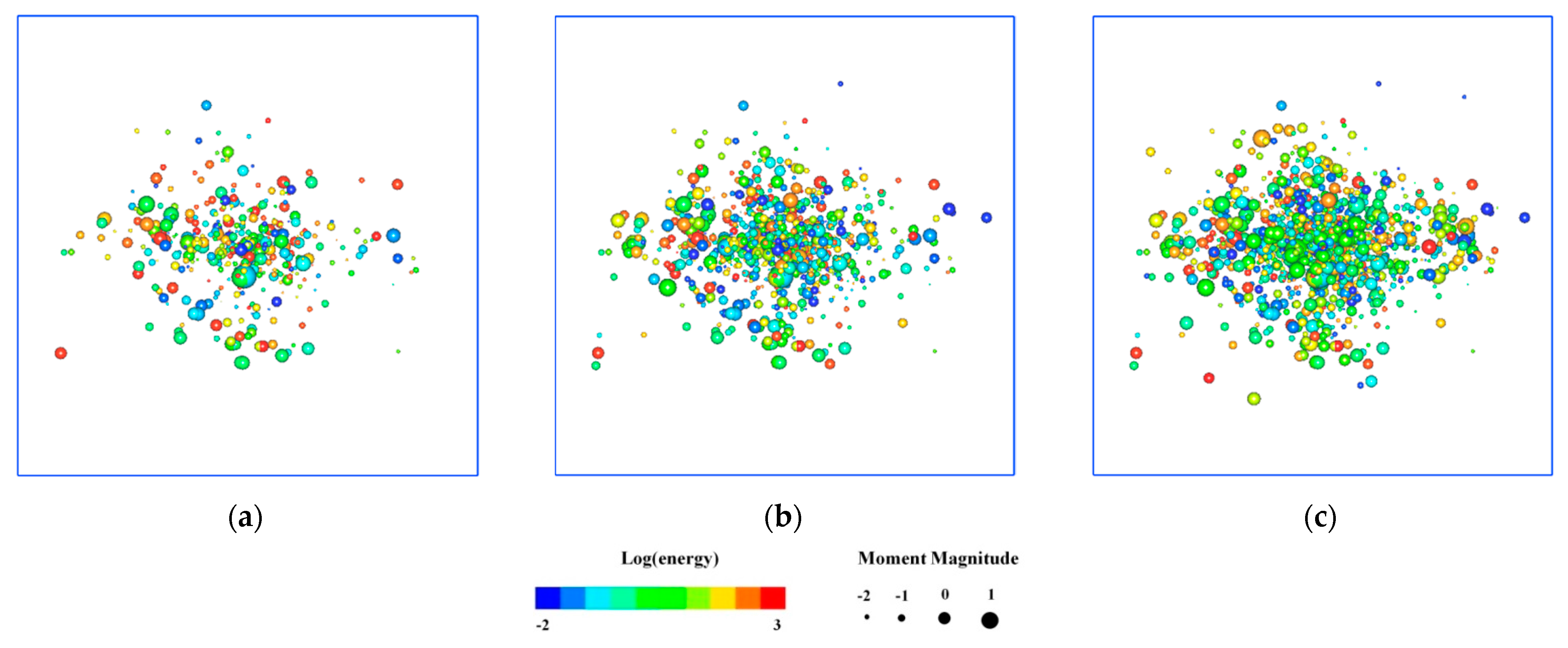
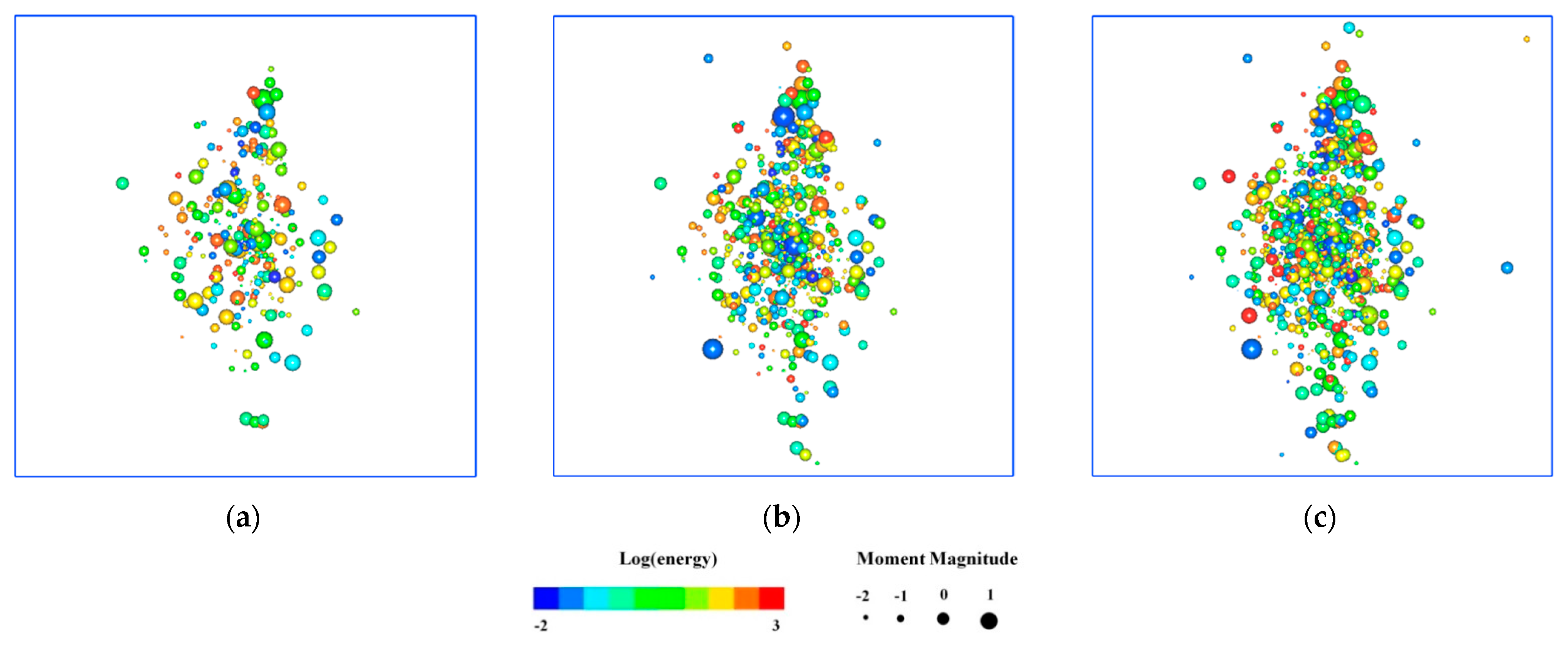
Only the location results of the AE events generated during six blasting operations were analysed here. The cumulative AE events generated in different samples after the second, fourth, and last blasting operation are displayed in three dimensions. Figure 4, Figure 5, Figure 6 and Figure 7 show the spatial location results of samples N1–1, N2–3, N3–1, and N4–2. The cumulative AE events generated in N1–1 after the second blasting operation are mainly distributed in left and right sides of the blast hole. AE events with a low energy level mainly occur in different zones except for the vicinity of the blast hole, where a small number of high-energy AE events are generated. After the fourth blasting operations, AE events accumulated around the blast hole and the growth and degree of accumulation thereof in the left and right zones are larger than those in the upper and lower zones around the blast hole. After the last blasting operation, numerous high-energy AE events occur in the left and right zones around the blast hole. With increasing number of blasting operations, the AE activity intensified and the number of high-energy AE events increased. As a result, the overall stability of the rock decreases. The elastic strain energy stored in the left and right-hand zones during application of the initial stress is higher than that stored in upper and lower zones of the samples owing to the applied stresses on left and right-hand sides being greater than those on upper and lower zones. The elastic energy stored in the samples is gradually released under the effect of blasting, therefore, more AE events are generated in left and right zones and the principal stress plays an obvious role of directional guidance in the generation and propagation of blasting-induced cracks.

6. Distribution of the Apparent Stress Field under the Effect of Blasting

Apparent stress, as a dynamic parameter describing the seismic source intensity, conveys abundant information about regional stress states, so is of significance when describing the fracturing process at a seismic source [20,21,22]. According to the Brune model [23], the apparent stress can be calculated thus:
σ A p p = μ E s M 0
where, μ represents the shear modulus of media in the seismic source area (c. 3.0 × 10⁴ MPa); E and M0 denote the wave energy radiated from the seismic source and seismic moment, which can be obtained through analysis and inversion of waveforms. To eliminate the influences of anomalously high values at several monitoring points (in terms of the apparent stress), logarithmic averaging as proposed by Archuleta et al. [24] is used to calculate the average value x of the apparent stress. The value is taken as the calculated result representing a single earthquake.
x ¯ = exp [ 1 N i = 1 N I n x i ]
x = [ 1 N 1 i = 1 N ( I n x i I n x ¯ ) 2 ] 1 2
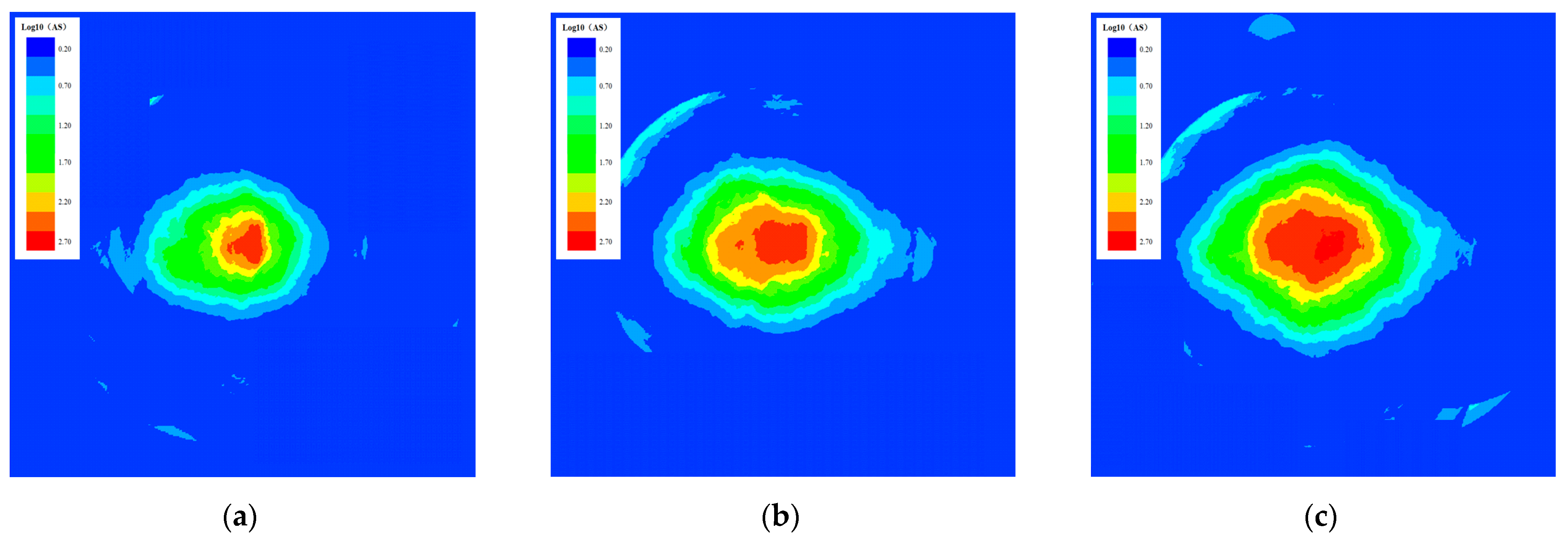
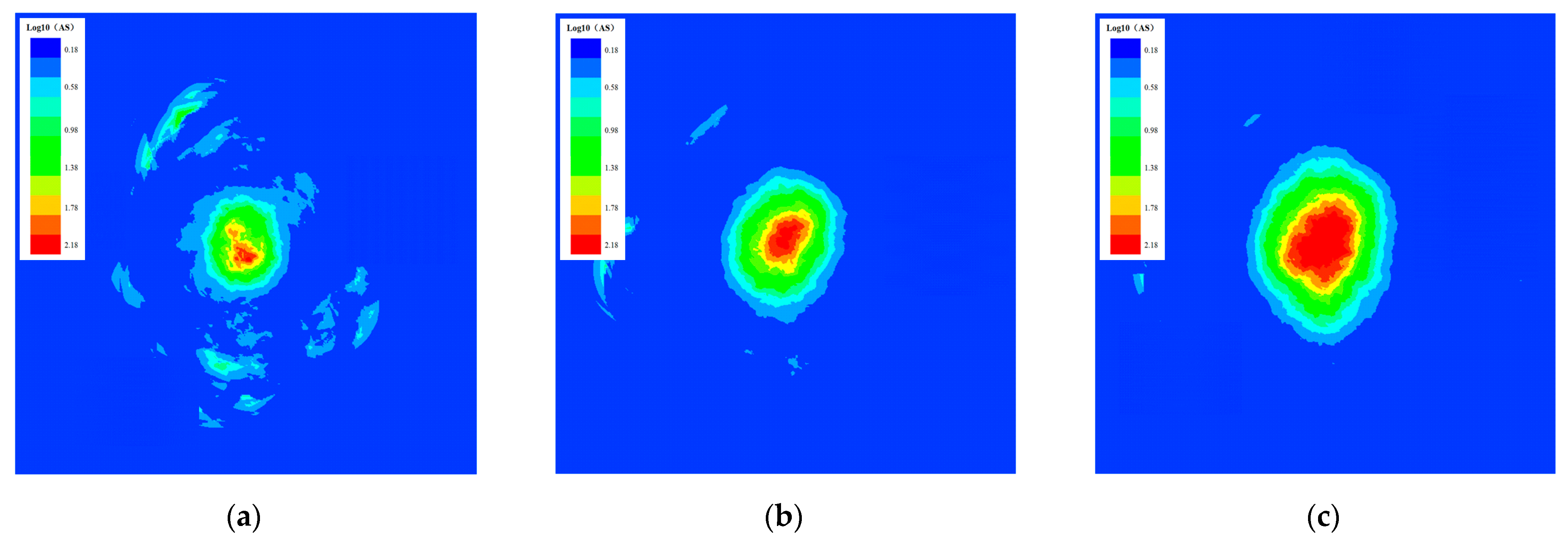
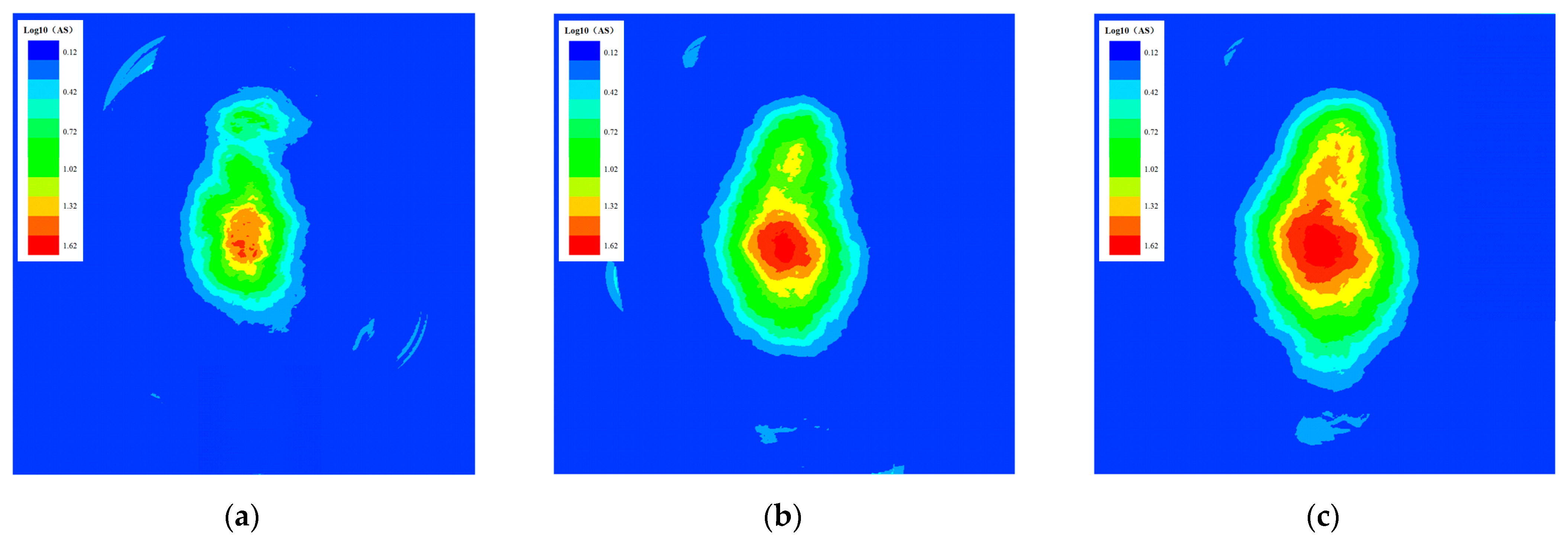
where, N and xi denote the number of monitoring points in the calculation and the calculated result for the ith monitoring point, respectively. The apparent stresses corresponding to AE information in the specimens N1–1, N2–3, N3–1, and N4–2 are calculated. The apparent stresses during the second, fourth, and last blasting operation are plotted (Figure 8, Figure 9, Figure 10 and Figure 11).
The apparent stress in specimen N1–1 is mainly concentrated on the zone around the blast hole after the second blasting operation. The distribution of the apparent stress is elliptical, with its long axis in the transverse direction after completing the fourth blasting operation. The stress concentration in the vicinity of the blast hole is more significant after the last blasting operation. The direction of propagation of the apparent stress is the same as the direction of the maximum principal stress. The direction of propagation and range of distribution of the apparent stress on specimen N2–3 are similar to those in specimen N1–1 while the apparent stress value is lower than that on specimen N1–1. The reason for this is that the principal stress on specimen N2–3 is still in the transverse direction and the distribution of the apparent stress in samples after blasting is related to the magnitude and direction of the internal principal stress of the samples. The transverse stress is equivalent to the longitudinal stress on specimen N3–1 before blasting; the apparent stress distributions exhibit no remarkable directionality after blasting and the degree of concentration of apparent stress increases the number of blasting operations. The direction of propagation of the apparent stress on specimen N4–2 is exactly opposite to that on specimen N1–1 and is consistent with the direction of the maximum principal stress. The stored elastic strain energy increases under load; huge amounts of energy are released from explosives when blasting, moreover, the elastic energy stored in the samples is released to generate numerous AE events in the vicinity of the blast hole. On this condition, the apparent stress accumulates and its distribution expands with increased blasting. The samples are subjected to different initial stresses, so the strain energy stored in different zones in the samples differs. More elastic strain energy is stored in the direction of action of the principal stress. Under the coupling and superposition effect between high stress and blasting-induced stress waves, the elastic energy stored in the samples is released during blasting and the maximum principal stress plays a significant role in directional guidance in the development of the apparent stress.

7. Numerical Simulation of the Blasting-Induced Damage in Rock

7.1. Design of the Test Schemes

In order to study the development pattern of rock mass damage zone after blasting under different lateral pressure coefficients, and compare it with the damage propagation law of microcracks in physical model experiments, numerical simulation of blasting damage was carried out. Numerical simulation of the dynamic load during blasting is undertaken using FLAC3D finite element software. The model measured 300 mm × 300 mm × 250 mm (length × width × height) and a pre-cut blast hole with a length of 10 mm and diameter of 8 mm was located at the centre of the model, some 123 mm from the top surface of the model. A three-dimensional geometric calculation model is established in FLAC3D, in which a total of 159,744 elements are used (Figure 12). The boundaries of the model are all fixed except for the top free face, which is not processed. The model is bi-directionally loaded, that is, the transverse stress value P1 is adjusted while keeping the longitudinal stress P2 (20 MPa) unchanged, such that the lateral pressure coefficients of the model are 2.0, 1.5, 1.0, and 0.5, respectively (Table 2).
It is necessary to find the related dynamic parameters and dynamic mechanical characteristics of rock at different loading rates when performing blast tests on rock in a high-stress environment. It is feasible to employ the formula for the dynamic compressive strength recommended by Li et al. [25] when the strain rate on such rock materials exceeds 30 s−1.
σ cd = 0.4 σ c ( ξ ) 1 / 3
where,  σ c  and  ξ  refer to the uniaxial compressive strength (MPa) and the strain rate (s−1), respectively. Owing to the strain rate around the blast hole for explosive charging being between 103 to 105 s−1, a strain rate of 104 s−1 is used here. The dynamic elastic modulus is generally larger than the static elastic modulus of rock. The relationship between the dynamic and static elastic moduli of rock is given by Eissa et al. [26]:
E d y n = ( E s / 10 0.02 ) 1 / 0.77 / ρ i
where,  E s , Edyn, and  ρ i  represent the static elastic modulus (GPa), dynamic elastic modulus (GPa), and density (g/cm3), respectively. When calculating the dynamic mechanical parameters of rock, it is necessary to calculate dynamic mechanical parameters of rock blocks and then compute mechanical parameters for the rock according to the modified Hoek-Brown formula. The simulation materials selected are only used to reveal the specific same test law. Because granite has the characteristics of compact structure, high compressive strength, low water absorption and high hardness, it is found that the damage area of granite after blasting loading is obviously expanded through numerical simulation comparison of various materials, which is the best match with the physical experiment results, so granite is selected as the numerical simulation model material. Granite is our chosen materials for testing and its dynamic and static mechanical parameters are summarised in Table 3.
It is experimentally supposed that the pressure is directly applied to the wall of the blast hole and the radius of the damage zone is mainly determined by the pressure applied thereto, therefore, the calculation method and loading path of the pressure on that wall are the key to numerical simulation of blasting. The pressure function initially introduced by Starfield and Pugliese and then modified by Jong et al. [27] is taken as the stress wave to simulate the time-history loading path of the dynamic pressure:
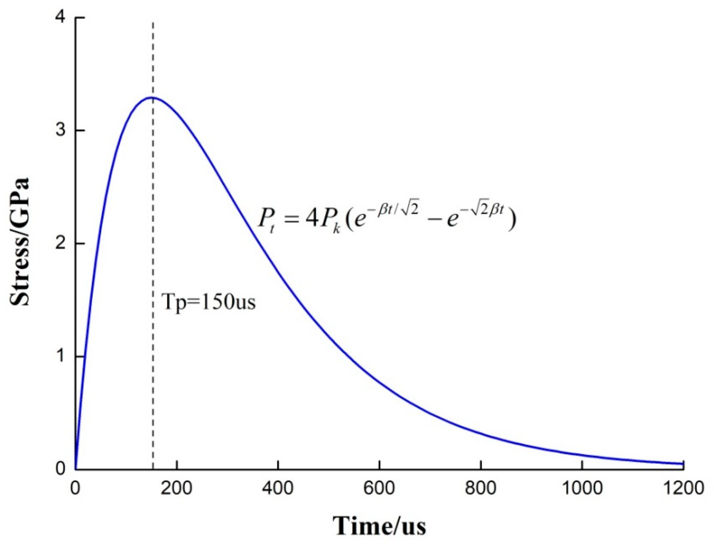
P t = 4 P b ( e β t / 2 e 2 β t )
where,  P t P b β , and t refer to the change in the pressure (Pa) on the blast wall with time, the pressure (Pa) applied thereto, the damping coefficient (1/s), and the action time (μs), respectively. When explosives are detonated in the blast hole, the pressure applied thereby can be expressed as follows:
P b = ρ e V d 2 8 ( d c d h ) 3
where, Vd ρ e d e , and  d h  denote the propagation velocity (m/s) of detonation waves, the density (kg/m3) of explosives, the diameter (cm) of the explosive cartridge, and the diameter (cm) of the hole, respectively. The peak pressure generated by blasting is generally determined according to the rise-time and the corresponding peak amplitude. The damping coefficient depends on the corresponding rise-time (tr) of the peak pressure:
β = 2 ln ( 1 / 2 ) t r
where, tr denotes the corresponding time (μs) to the explosion stress peak. The numerical simulation is conducted based on related parameters of the emulsion explosives in Table 4. The corresponding rise-time tr to peak pressure is determined to be 150 μs and the time-history curve of the peak stress during the loading is displayed in Figure 13. The viscous boundary condition proposed by Lysmer and Kuhlemeyer (1969) is considered as the dynamic boundary condition for reducing the stress wave reflection during dynamic calculation. The local damping value (0.05) is selected as the damping value in later dynamic analysis.

7.2. Analysis of Test Results

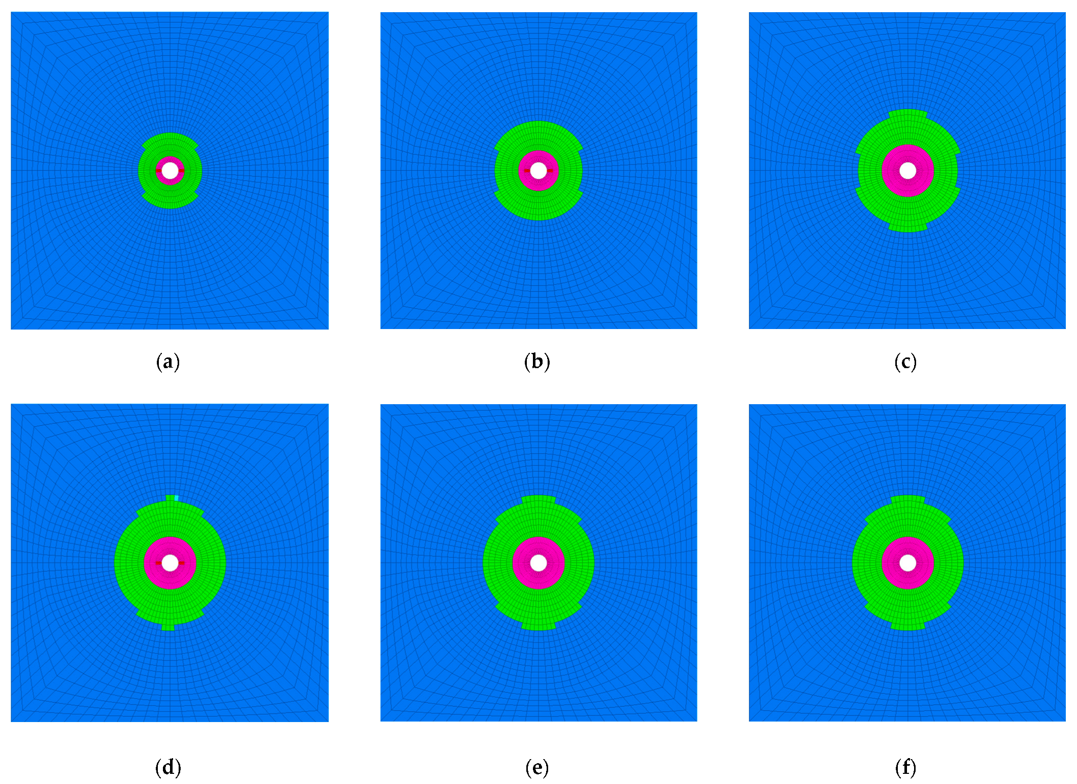
The development of the damage zone caused by blasting was monitored. The development of the damage zone with the time-history of applied stress is shown in Figure 14 by taking the model M4–1 as the example. The result shows that when the peak stress rise time is not reached 150 μs, the damage zone induced by blasting gradually increases in size before the blasting-induced stress waves (Figure 14a–d). The damage zone induced by blasting is similar after the blasting-induced stress waves reach the peak stress (Figure 14e,f). This implies that the damage generated in the rock during the rising stage of the peak stress waves decisively influences the global failure process. The longitudinal stress applied before blasting in the M4–1 model is larger than the transverse stress and the static stress affects the propagation of detonation waves, which presents a guiding effect on the tensile failure zones. The tensile failure after blasting mainly develops towards the upper and lower zones of the model while the shear failure is not influenced by the static stress.
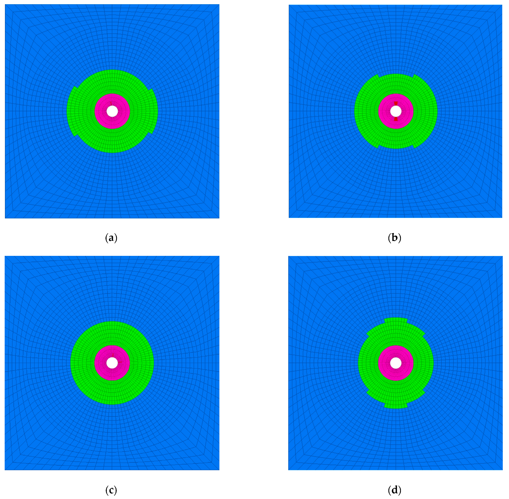
Figure 15 displays the distributions of the final damage patterns of various samples after blasting. The tensile failure patterns of rock under blasting-induced disturbance differ greatly under the effects of different initial stresses: the damage zone in models M1–1 and M2–1 expands towards the left and right-hand zones; the damage zone in model M3–1 uniformly circumferentially extends outwards from the blast hole (at its centre) and that in model M4–1 expands towards the upper and lower zones. When fracturing rock by using the drilling and blasting method in a high-stress environment, rock failure is a dynamic process evolving under the coupling of the effects of the geostress and blasting. The presence of the initial stress field influences the propagation of explosive detonation waves, which delivers an obvious guiding effect on the development of the tensile failure zones. The level of the shear failure and the pattern of the shear failure zones are not significantly affected by the initial geostress field. The direction of propagation of microcracks in the rock is coincident with the direction of the maximum principal stress on the samples under the aforementioned coupling effect. The maximum principal stress plays an obvious role of directional guidance in the initiation and propagation of blasting-induced cracks. The result obtained through numerical simulation is the same as that attained experimentally.

8. Conclusions

(1)
Both stress loading and blasting disturbance will cause damage and destruction in the specimen, stress loading has the greatest contribution to specimen failure. The single sample test shows that the proportion of AE signal generated by explosion disturbance increases with the increase of explosion times. The test results of different groups of samples show that the higher the stress level of rock mass is, the higher the AE signal ratio generated by blasting disturbance is, and the blasting disturbance is more likely to damage and destroy the rock mass in high stress state.
(2)
The spatial distribution of AE events shows that the maximum principal stress plays a remarkable role of directional guidance in the generation and propagation of blasting-induced cracks. The strain energy stored in different zones of the samples differs greatly due to different initial stress environments and the elastic energy stored in the samples is gradually released during blasting. Therefore, the AE events in the direction of the maximum principal stress of the sample after blasting are significantly increased.
(3)
The results of numerical simulation reveal that the damage zone induced by blasting gradually extends due to the effect of dynamic loads before the blasting-induced stress waves reach the peak stress. The presence of the initial stress field influences the propagation of explosive detonation waves, thus playing an obvious role of directional guidance in the development of the tensile failure zones. The direction of development of the damage zones is consistent with the direction of the maximum principal stress.

Author Contributions

Formal analysis, X.S.; Resources, S.Z.; Writing–original draft, G.L.; Writing–review & editing, D.W. All authors have read and agreed to the published version of the manuscript.

Funding

This work was financially supported by Yibin College Sailing Project (No. 412–2020QH10). The Project supported By Open Fund (PLC 2020043) of State Key Laboratory of Oil and Gas Reservoir Geology and Exploitation (Chengdu University of Technology).

Institutional Review Board Statement

Not applicable.

Informed Consent Statement

Not applicable.

Data Availability Statement

Not applicable.

Conflicts of Interest

The authors declare no conflict of interest.

References

  1. Wang, K.; Pan, H.; Zhang, T.; Wang, H. Experimental study on the radial vibration characteristics of a coal briquette in each stage of its life cycle under the action of CO2 gas explosion. Fuel 2022, 320, 123922. [Google Scholar] [CrossRef]
  2. Du, K.; Liu, M.; Yang, C.; Tao, M.; Feng, F.; Wang, S. Mechanical and Acoustic Emission (AE) characteristics of rocks under biaxial confinements. Appl. Sci. 2021, 11, 769. [Google Scholar] [CrossRef]
  3. Lin, X.; Li, B.; Li, P.; Ding, Q.; Huang, M. Study of the evolution characteristics of Microseismic Events during the excavation of underground caverns under high geostress. Appl. Sci. 2022, 12, 12145. [Google Scholar] [CrossRef]
  4. Huo, X.; Shi, X.; Qiu, X.; Chen, H.; Zhou, J.; Zhang, S.; Rao, D. Study on rock damage mechanism for lateral blasting under high in situ stresses. Appl. Sci. 2021, 11, 4992. [Google Scholar] [CrossRef]
  5. Gong, F.; Hao, Y.; Yong, L. The Effect of High Loading Rate on the Behaviour and Mechanical Properties of Coal-Rock Combined Body. Shock. Vib. 2018, 2018, 4374530. [Google Scholar] [CrossRef] [Green Version]
  6. Li, J.C.; Rong, L.F.; Li, H.B.; Hong, S.N. An SHPB Test Study on Stress Wave Energy Attenuation in Jointed Rock Masses. Rock Mech. Rock Eng. 2018, 2018, 403–420. [Google Scholar] [CrossRef]
  7. Sun, C.; Li, C.; Wei, X. Research on seismic wave quality factor of marble jointed rock mass under SHPB impact. Appl. Sci. 2022, 12, 10875. [Google Scholar] [CrossRef]
  8. Christensen, R.; Swanson, S.; Brown, W. Split-Hopkinson-bar tests on rock under confining pressure. Exp. Mech. 1972, 12, 508–513. [Google Scholar] [CrossRef]
  9. Li, X.; Zhou, Z.; Lok, T.S.; Hong, L.; Yin, T. Innovative testing technique of rock subjected to coupled static and dynamic loads. Int. J. Rock Mech. Min. Sci. 2008, 45, 739–748. [Google Scholar] [CrossRef]
  10. Li, Y.; Peng, J.; Zhang, F.; Qiu, Z. Cracking behavior and mechanism of sandstone containing a pre-cut hole under combined static and dynamic loading. Eng. Geol. 2016, 213, 64–73. [Google Scholar] [CrossRef]
  11. He, C.; Yang, J.; Qi, Y. Laboratory study on the dynamic response of rock under blast loading with active confining pressure. Int. J. Rock Mech. Min. Sci. 2018, 102, 101–108. [Google Scholar] [CrossRef]
  12. Zhu, W.C.; Gai, D.; Wei, C.H.; Li, S.G. High-pressure air blasting experiments on concrete and implications for enhanced coal gas drainage. J. Nat. Gas Sci. Eng. 2016, 36, 1253–1263. [Google Scholar] [CrossRef] [Green Version]
  13. Zhang, F.; Peng, J.; Qiu, Z.; Chen, Q.; Li, Y.; Liu, J. Rock-like brittle material fragmentation under coupled static stress and spherical charge explosion. Eng. Geol. 2017, 220, 266–273. [Google Scholar] [CrossRef]
  14. Yi, C.; Johansson, D.; Greberg, J. Effects of in-situ stresses on the fracturing of rock by blasting. Comput. Geotech. 2017, 104, 321–330. [Google Scholar] [CrossRef]
  15. Hu, Y.; Lu, W.; Chen, M.; Yan, P.; Zhang, Y. Numerical simulation of the complete rock blasting response by SPH–DAM–FEM approach. Simul. Model. Pract. Theory 2015, 56, 55–68. [Google Scholar] [CrossRef]
  16. Ma, G.W.; An, X.M. Numerical simulation of blasting-induced rock fractures. Int. J. Rock Mech. Min. Sci. 2008, 45, 966–975. [Google Scholar] [CrossRef]
  17. Jian-po, L.; Chang-yin, Z.; Ying-tao, S.; Ren, W.; Gang, L.; Shi-da, X. Temporal-spatial evolution of acoustic emission during progressive fracture processes around tunnel triggered by blast-induced disturbances under uniaxial and biaxial compression. Tunn. Undergr. Space Technol. 2020, 96, 103229. [Google Scholar] [CrossRef]
  18. Long, Y.; Liu, J.P.; Lei, G.; Si, Y.T.; Zhang, C.Y.; Wei, D.C.; Shi, H.X. Progressive fracture processes around tunnel triggered by blast disturbances under biaxial compression with different lateral pressure coefficients. Trans. Nonferrous Met. Soc. China 2020, 30, 2518–2535. [Google Scholar] [CrossRef]
  19. Yuan-hui, L.; Gang, L.; Shi-da, X.; Da-wei, W. The spatial-temporal evolution law of microseismic activities in the failure process of deep rock masses. J. Appl. Geophys. 2018, 154, 1–10. [Google Scholar] [CrossRef]
  20. Choy, G.L.; Boatwright, J.L. Global patterns of radiated seismic energy and apparent stress. J. Geophys. Res. Solid Earth. 1995, 100, 18205–18228. [Google Scholar] [CrossRef] [Green Version]
  21. Lasocki, S.; Orlecka-Sikora, B. Seismic hazard assessment under complex source size distribution of mining-induced seismicity. Tectonophysics 2008, 456, 28–37. [Google Scholar] [CrossRef]
  22. Newman, A.V.; Okal, E.A. Teleseismic estimates of radiated seismic energy: The E/M 0 discriminant for tsunami earthquakes. J. Geophys. Res. Solid Earth. 1998, 103, 26885–26898. [Google Scholar] [CrossRef]
  23. Brune, J.N.; Brune, J.N. Tectonic stress and the spectra of seismic shear waves from earthquakes. J. Geophys. Res. 1970, 75, 4997–5009. [Google Scholar] [CrossRef] [Green Version]
  24. Archuleta, R.J.; Cranswick, E.; Mueller, C.; Spudich, P. Source parameters of the 1980 Mammoth Lakes, California earthquake sequence. J. Geophys. Res. Solid Earth. 1982, 87, 4595–4607. [Google Scholar] [CrossRef]
  25. Li, J.C.; Li, H.B.; Ma, G.W.; Zhou, Y.X. Assessment of underground tunnel stability to adjacent tunnel explosion. Tunn. Undergr. Space Technol. Inc. Trenchless Technol. Res. 2013, 35, 227–234. [Google Scholar] [CrossRef]
  26. Eissa, E.; Kazi, A. Relation between static and dynamic Young’s moduli of rocks. Int. J. Rock Mech. Min. Geomech. Abstr. 1988, 25, 479–482. [Google Scholar] [CrossRef]
  27. Yilmaz, O.; Unlu, T. Three dimensional numerical rock damage analysis under blasting load. Tunn. Undergr. Space Technol. Inc. Trenchless Technol. Res. 2013, 38, 266–278. [Google Scholar] [CrossRef]
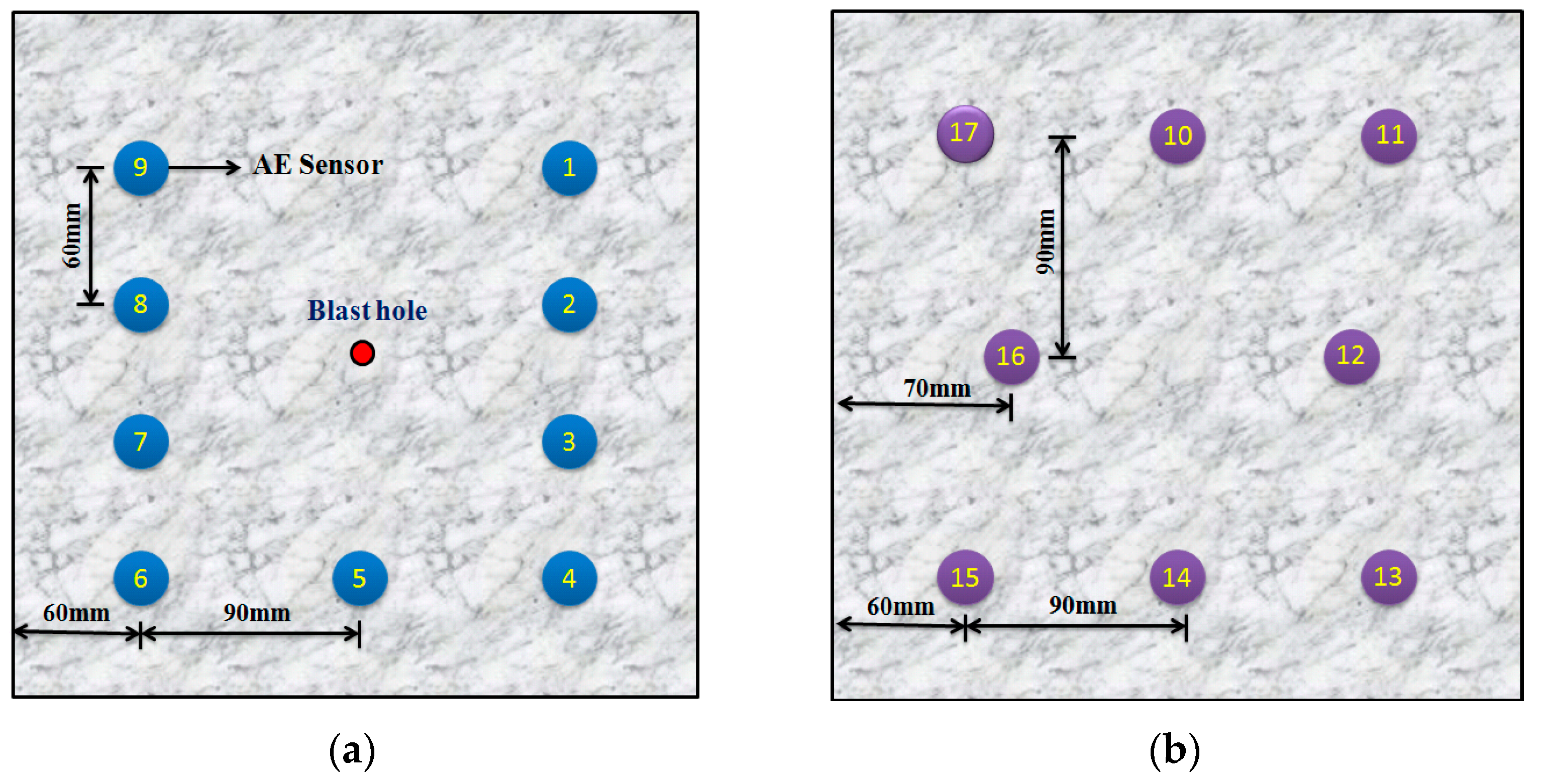
Figure 1. AE sensors arrangement: (a) sensors on the front face; (b) sensors on the back face.
Applsci 13 02781 g001
Figure 2. Test model and loading system.
Applsci 13 02781 g002
Figure 3. AE time series features. (a) N1–1; (b) N2–3; (c) N3–1; (d) N4–2.
Applsci 13 02781 g003aApplsci 13 02781 g003b
Figure 4. Spatial evolution of cumulative AE events in specimen N1–1. (a) Second blast; (b) Fourth blast; (c) Last blast.
Applsci 13 02781 g004
Figure 5. Spatial evolution of cumulative AE events in specimen N2–3. (a) Second blast; (b) Fourth blast; (c) Last blast.
Applsci 13 02781 g005
Figure 6. Spatial evolution of cumulative AE events in specimen N3–1. (a) Second blast; (b) Fourth blast; (c) Last blast.
Applsci 13 02781 g006
Figure 7. Spatial evolution of cumulative AE events in specimen N4–2. (a) Second blast; (b) Fourth blast; (c) Last blast.
Applsci 13 02781 g007
Figure 8. Distribution of apparent stress in N1–1 with time. (a) Second blast; (b) Fourth blast; (c) Last blast.
Applsci 13 02781 g008
Figure 9. Distribution of apparent stress in N2–3 with time. (a) Second blast; (b) Fourth blast; (c) Last blast.
Applsci 13 02781 g009
Figure 10. Distribution of apparent stress in N3–1 with time. (a) Second blast; (b) Fourth blast; (c) Last blast.
Applsci 13 02781 g010
Figure 11. Distribution of apparent stress in N4–2 with time. (a) Second blast; (b) Fourth blast; (c) Last blast.
Applsci 13 02781 g011
Figure 12. FLAC3D computing grid model.
Applsci 13 02781 g012
Figure 13. Blasting load time-lapse loading curve.
Applsci 13 02781 g013
Figure 14. Development of the damaged zone in specimen M4–1 with time. (a) 30 μs; (b) 60 μs; (c) 90 μs; (d) 120 μs; (e) 150 μs; (f) 500 μs. Applsci 13 02781 i001 No damage Applsci 13 02781 i002 Shear failure Applsci 13 02781 i003 Tensile failure.
Applsci 13 02781 g014
Figure 15. Cloud maps of plastic zones under different static stresses. (a) M1–1; (b) M2–1; (c) M3–1; (d) M4–1. Applsci 13 02781 i001 No damage; Applsci 13 02781 i002 Shear failure; Applsci 13 02781 i003 Tensile failure.
Applsci 13 02781 g015
Table 1. Experimental blasting schemes.
Test PlanModel NumberP2/MPaP1/MPaNumber of Blasting OperationsMass of Charge/gLateral Pressure Coefficient
1N1–1, N1–2 and N1–31632612.0
2N2–1, N2–2 and N2–31624611.5
3N3–1, N3–2 and N3–31616611.0
4N4–1, N4–2 and N4–3168610.5
Table 2. Test schemes for numerical simulation.
Test PlanModel NumberP2/MPaP1/MPaBlast NumberLateral Pressure Coefficient
1M1–1204012.0
2M2–1203011.5
3M3–1202011.0
4M4–1201010.5
Table 3. Mechanical parameters of granite.
ConditionsShear Modulus (GPa)Bulk Modulus (GPa)Tensile Strength (MPa)Friction Angle (°)Cohesion (MPa)
Static33.6563.9244.1920.1
Dynamic42.270.333.844.19173
Table 4. The parameter information of the emulsion explosives.
Explosive TypeThe Density (kg/m3)The Propagation Velocity (m/s) of Detonation WavesRise-Time to Peak Pressure (μs)
Emulsion explosives1250558250
Disclaimer/Publisher’s Note: The statements, opinions and data contained in all publications are solely those of the individual author(s) and contributor(s) and not of MDPI and/or the editor(s). MDPI and/or the editor(s) disclaim responsibility for any injury to people or property resulting from any ideas, methods, instructions or products referred to in the content.