1. Introduction
As a solution to the current issues of global warming and CO
2 emissions, the dominance of EVs is increasing in the transportation sector [
1,
2]. Owing to the obstructions in full EVs, the popularity of hybrid EVs and small capacity E-mobility applications such as the electric tricycle, motorcycle, and bicycle has been increasing. However, some of the well-known producers of EVs have recently switched to higher-voltage batteries to obtain the advantages of lower current, greater power density, and quicker charging periods [
3]. As a crucial part of electric transportation, traction inverters have been the focus of several research initiatives. The rise in battery capacity for EVs has forced development for traction inverters with larger power capacity. The excessive temperature rise in traction inverters could reduce their performance and operating life and in some cases result in their failure [
4]. Therefore, an effective cooling strategy is needed for the thermal management of traction inverters to stop them from running at a dangerous temperature.
The air cooling is not capable of dissipating the heat effectively from the power electronics with high energy density [
5]. Therefore, liquid cooling is preferred in high-power applications such as traction inverters of EVs owing to its superior heat dissipation properties [
6,
7]. Sakanova et al. have investigated the cooling performance of power electronics converter by comparing cold plates with U-shaped copper tube and those with serpentine copper tube. The cold plate with a serpentine copper tube shows the enhanced cooling performance of power electronics converter compared to the cold plate with a U-shaped copper tube [
8]. Nawawi et al. have designed a hybrid cold plate and copper tube cooling system using water coolant for the thermal management of SiC-MOSFET inverter with power density of 6.49 kW/kg [
9]. Karimi et al. have achieved the maximum junction temperature of 82.2 °C for three phase inverters using eight pass cold plate heat sinks [
10]. Tran et al. have concluded that the liquid cooled cold plate with straight fins shows 6 °C lower coolant temperature compared to that without fins for cooling of 60 kW converter [
11]. Boteler et al. have proposed the liquid cooled finned heat sink to investigate the thermal characteristics of dual MOSFET power module under the influence of inlet temperature and flow rate of coolant. The proposed cooling only shows the temperature rise of 24 °C for the input power of 158 W/cm
2 [
12]. Liang et al. have studied the cooling performance of a motor inverter with a high efficiency liquid cooled heat sink under the effects of channel gap and flow rate. The motor inverter temperature rise is 14 °C lower for multiple small cooling channel structures compared to single channel structure [
13].
To create a channel with a serpentine copper tube, it should be embedded with an aluminium baseplate. Therefore, to eliminate this disadvantage, the cold plate heat sink with commercial-off-the-shelf (COTS) has been discovered for the liquid cooling of power electronics. However, the heat dissipation performance of cold plate heat sink with COTS is poor in the case of high-power density electronic devices [
14]. It is recommended that the cooling channels that are placed below the power electronics could remove the heat effectively [
15].
In a hydraulic cooling system, the pump converts the mechanical energy of the drive motor into energy of liquid flow, which serves to move the working fluid through channels, takes heat from energy source, and directs it to radiator for cooling and reuse. The hydraulic cooling system enables the disadvantage of higher power consumption for circulation of coolant to achieve the desired cooling performance of high energy density devices. In connection with this is the fact that more and more manufacturers of EVs want to provide a more moderate price with greater power. However, the challenge arises to maintain the desired thermal management of higher energy density components in EVs with reduced electricity consumption [
16,
17]. To resolve these issues related to conventional pumps, MHD pumps have been the subject of research in the last few years. Owing to several benefits of no moving parts, no contact with coolant, and reduced energy consumption over typical pumps, MHD pumps have been accepted in a wide range of applications including biological fields such as blood pumping, solar applications, spaceship applications, molten metal pumping, and heat transfer systems [
18]. Furthermore, the compact and simple structure of MHD pumps offers their suitability for miniaturization applications such as microelectromechanical systems (MEMS), microfluidic systems, and micro cooling systems [
19,
20]. Zhao et al. have investigated the flow characteristics of Maxwell fluids in rectangular MHD pumps under the influence of an alternating current electric field and observed that the higher values of velocity have resulted because of a larger Hartmann number at oscillating Reynolds number [
21]. Kiyasatfar et al. have studied the thermal and flow characteristics of fluid flow in a direct-current-based MHD pump under the influence of channel size, applied current, and magnetic field intensity. With an increase in applied current, the maximum velocity of fluid flow increases and results into a flat velocity profile when the Hartmann number increases [
22].
Magnetic nanofluids, also known as the ferrofluids, are stable colloidal suspensions of ultrafine single domain superparamagnetic nanoparticles into a base fluid [
23]. A ferrofluid, on the other hand, retains its “fluid” state even when subjected to the strong magnetic fields (10 kG) [
24]. Magnetic nanofluids are often used in cooling systems because they can transfer heat effectively due to high thermal conductivity and an ability to change the flow properties in the presence of a magnetic field. When a magnetic field is applied to ferrofluid, the magnetic nanoparticles align with the field and create a structured arrangement [
25]. Therefore, magnetic nanofluids are the best candidate to employ in MHD pump-based cooling systems to improve the electromagnetic and heat transfer performance. Khan et al. have studied the magnetic dipole effect on thermal and flow characteristics of nanofluid flow over a curved stretching surface. The temperature improves and velocity decreases under the influence of the magnetic dipole effect [
26]. Furthermore, Khan et al. have concluded that under the influence of ferromagnetism, the temperature of nanofluid increases and velocity of nanofluid decreases [
27]. Miroshnichenko et al. have investigated the influence of magnetic field orientations on MHD natural convection heat transfer in a partially opened trapezoidal cavity. The MHD natural convection heat transfer decreases with an increase in value of uniform magnetic field [
28]. Shirvan et al. have optimized the Nusselt number of MHD flow using Cu-water nanofluid in a square cavity under different configurations of inlet and outlet ports [
29]. Larimi et al. have studied the heat transfer of magnetic nanofluid under the influence of non-uniform transverse magnetic fields and Reynolds number. The heat transfer in magnetic nanofluid is significant under the external magnetic field at a low Reynolds number [
30]. Kolsi et al. have optimized the inclination angle of a cubical enclosure for enhanced heat transfer of CNT-water nanofluid in an MHD pump and superior natural convection is observed at inclination angle of 180° [
31].
The MHD pump offers several benefits over the conventional pump in cooling applications. However, the open literature reveals that the MHD pump is employed for cooling of energy sources with limited power density. If the MHD pump is combined with a conventional pump, in that case the power consumption load from the conventional pump could be reduced and also MHD pump-based cooling could be targeted for thermal management of higher power density applications. There are research opportunities on optimizing the design and operation of a hybrid approach that combines convectional pump and MHD pump-based cooling to significantly enhance the cooling capabilities of electronic devices and systems with increasing energy densities. To the best of the authors’ knowledge and conducted literature review, the open literature is missing a concrete research study on the thermal management of traction inverters with high power density using hybrid MHD-convectional pump-based cooling systems. The research gaps in the open literature are explored by proposing the hybrid MHD-conventional pump-based cooling system for the thermal management of higher power density traction inverters in the present work. Therefore, the objective of the present study is to numerically investigate the cooling performance characteristics of traction inverters using MHD pump-based cooling systems with water and ferrofluid coolants. The influence of various conditions of inlet velocity, electromagnetic parameters, and volume fraction is studied on outlet velocity, inverter maximum temperature and Nusselt number. The cooling performance characteristics of traction inverters are investigated under the influence of various factors using MHD pump-based cooling systems with and without integration of conventional pumps.
3. Results and Discussion
The results and discussion section includes the validation of the proposed numerical model followed by discussion about effect of inlet velocity, effect of electromagnetic parameters, and effect of ferrofluid volume fraction on cooling performance of an MHD pump-based cooling system for a traction inverter. The magnetic field intensity and voltage are considered as electromagnetic parameters and the outlet velocity, inverter maximum temperature, and Nusselt number are considered as cooling performance parameters.
3.1. Validation
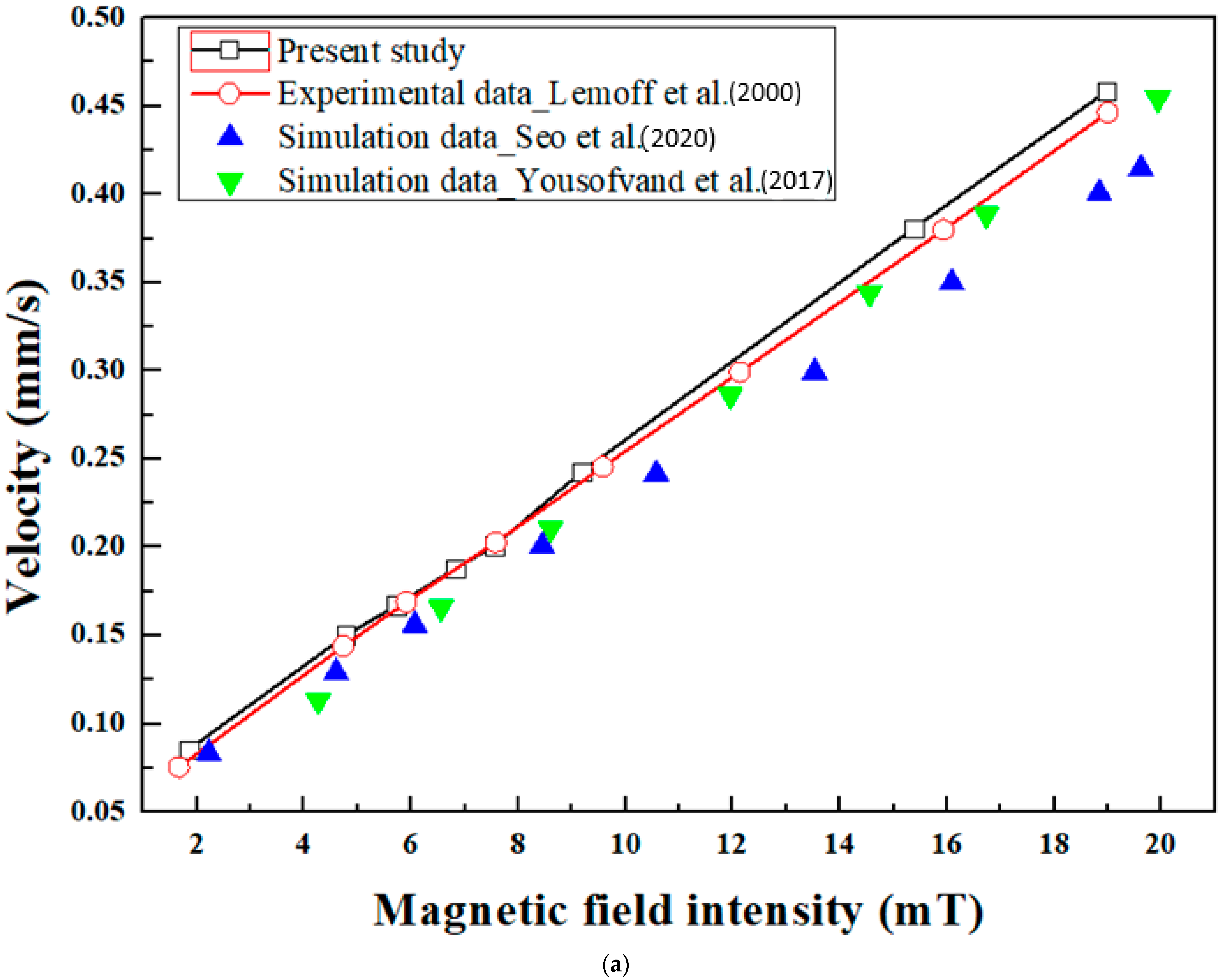
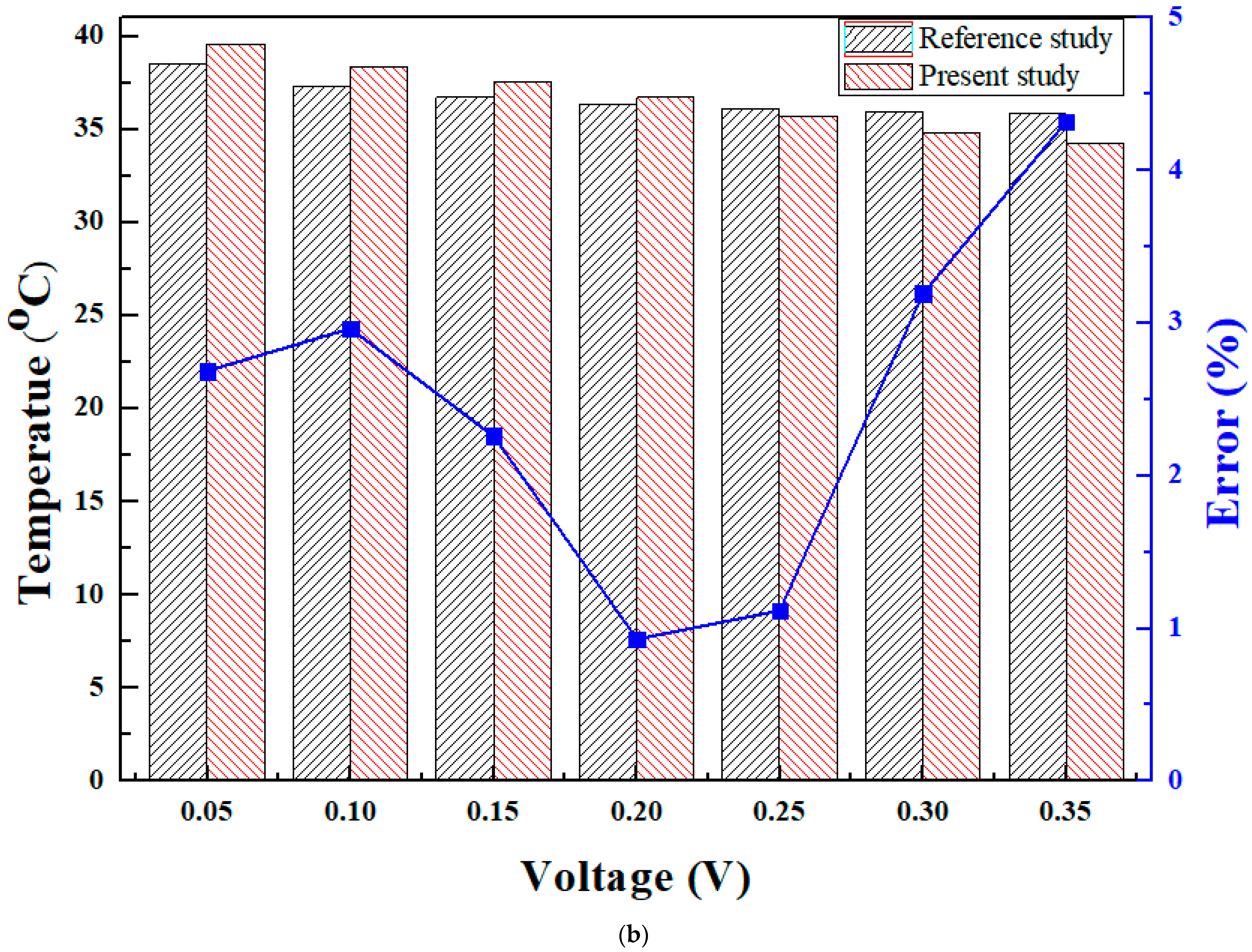
The numerical results of velocity and temperature are compared with corresponding results proposed in various literature studies as shown in
Figure 5. The velocity of coolant in the cooling channel owing to the Lorentz force generated by the MHD pump is considered as one validation parameter. The velocity validation is conducted for the applied current of 15 mA and magnetic field intensity from 2 mT to 20 mT. The present numerical results of velocity show closer agreement with linear fit of corresponding experimental velocity results proposed by Lemoff et al. [
43]. Under various conditions of magnetic field, the numerical velocity is validated with experimental velocity within maximum error of 2.52% and average error of 0.8%. Previous research studies proposed by Seo et al. and Yousofvand et al. [
44,
45] have compared the numerical results of velocity with the same experimental results of Lemoff et al. To show the accuracy of present simulation results with corresponding experimental results, the simulated velocity results from aforementioned studies have been reflected in
Figure 5a. As can be observed, the present numerical results of velocity show closer agreement and relatively lower error with experimental results compared to simulated velocity results presented in the literature studies for the same configuration. The simulated temperatures in the present study are compared with corresponding temperature results proposed by Seo et al. under the same voltage conditions. The simulated temperature in the present study shows closer agreement to corresponding temperature results from the reference study, with a maximum error of 4.32%. The predicted results from the proposed numerical model are reliable as the validation is within the acceptable limit of 5%, hence, the numerical model could be adopted for further simulations in the present work.
3.2. Effect of Inlet Velocity
The variation in outlet velocity generated in the cooling channel for both water and ferrofluid cooling under the influence of inlet velocity and voltage is depicted in
Figure 6. The outlet velocity is the total velocity generated as a combination of constant velocity of the inlet coolant path and the MHD pump inlet coolant path. Water velocity is only dominated by the constant velocity inlet coolant path because water has no self-circulation characteristics in the presence of the MHD pump. Therefore, the outlet velocity remains constant with changes in voltage for each inlet velocity in the case of water cooling. However, with the increase in inlet velocity, the outlet velocity of water increases owing to the rise in driving force. For water cooling, the outlet velocities of 0.81 mm/s, 1.21 mm/s, 1.61 mm/s, 2.02 mm/s, and 4.03 mm/s are evaluated for inlet velocities of 2 mm/s, 3 mm/s, 4 mm/s, 5 mm/s, and 10 mm/s, respectively. The ferrofluid depicts self-circulation characteristics in the presence of the MHD pump under the influence of electromagnetic parameters, hence, the outlet velocity in the case of ferrofluid cooling is contributed to by both constant velocity coolant path as well as the MHD pump coolant path. In water cooling, the velocity is generated only by the constant velocity coolant path, whereas in ferrofluid cooling, the velocity is generated by the constant velocity coolant path as well as the MHD pump. Therefore, the outlet velocity in the case of ferrofluid cooling is superior compared to that of water cooling under the same conditions. Furthermore, the outlet velocity of ferrofluid increases linearly with increase in voltage for each inlet velocity because the Lorentz force in the MHD pump, which drives the ferrofluid, increases with an increase in voltage. The maximum outlet velocity is found at a higher voltage where the Lorentz force is at its maximum. In the case of ferrofluid cooling, the outlet velocity increases from 1.7 mm/s to 6.56 mm/s for inlet velocity of 2 mm/s, 1.78 mm/s to 6.62 mm/s for inlet velocity of 3 mm/s, 1.87 mm/s to 6.86 mm/s for inlet velocity of 4 mm/s, 1.97 mm/s to 6.63 mm/s for inlet velocity of 5 mm/s and 2.65 mm/s to 7.02 mm/s for inlet velocity of 10 mm/s with increase in voltage from 0.1 V to 0.5 V.
The Lorentz force generated using the MHD pump is low at a lower voltage or lower value of magnetic field intensity. The Lorentz force with lower magnitude is not sufficient enough to drive the ferrofluid in a perpendicular flow direction, which results in ferrofluid flow in the reverse direction in terms of backflow. Therefore, the critical values of magentic field intensity and voltage are needed to avoid the backflow of ferrofluid from one coolant path to another coolant path. To understand this phenomena, the flow streamlines of ferrofluid in cooling channel in the case of with backflow at 10 mm/s inlet velocity and 0.1 V and that of without backflow at 10 mm/s inlet velocity and 0.5 V are depicted in
Figure 7. As shown in
Figure 7, in the case of higher voltage of 0.5 V, the generated Lorentz force using the MHD pump is significant enough to drive the ferrofluid flow in a perpendicular direction without any backflow. The backflow reduces the amount of coolant that should be passed through the channel for inverter cooling, owing to the reversal of ferrofluid flow. Furthermore, the backflow disturbs the uniformity of ferrofluid flow in the cooling channel beneath the inverter. Therefore, the amount of heat that should be carried by ferrofluid from the inverter is affected by backflow. The temperature contours of the traction inverter in the case of without backflow and with backflow are shown in
Figure 7. The backflow affects the cooling of the traction inverter such that the inverter maximum temperature is high in the case of backflow compared to without backflow.
In ferrofluids, natural convection can be influenced by the magnetic field, causing the ferrofluid to flow differently than it would in the absence of a magnetic field. However, in the present MHD pump-based cooling system, the ferrofluid experiences heat transfer through mixed convection phenomena because the MHD pump offers Lorentz force as a combination of magnetic and electric fields. In ferrofluids, when the magnetic and electric fields create a driving force for fluid motion, it augments the natural convective forces. Therefore, the heat transfer in ferrofluid is dominated significantly by mixed convection and superior compared to natural convection, due to presence of both magnetic and electric fields through the MHD pump. Furthermore, in cases when the conventional pump is enabled using constant velocity coolant path in addition to the MHD pump, the heat transfer in ferrofluid could even transit from mixed convection to forced convection.
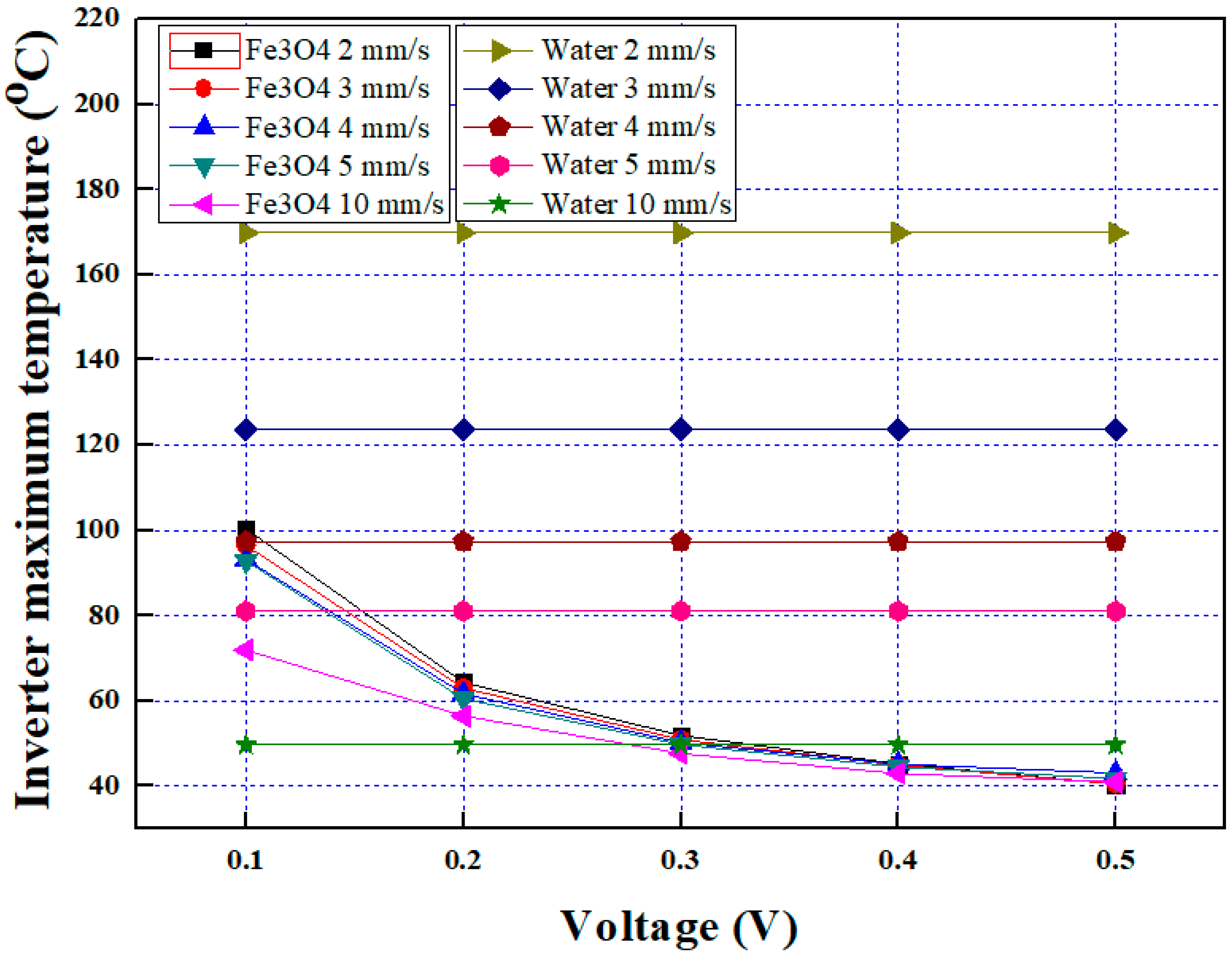
The comparison of the inverter maximum temperature for water and ferrofluid cooling considering various conditions of inlet velocity and voltage is shown in
Figure 8. The MHD pump does not contribute to the circulation of water, therefore, with change in voltage, the inverter maximum temperature remains constant for each inlet velocity in the case of water cooling. The lack of self-circulation in the case of the water cooling results in higher inverter maximum temperature, however, the constant velocity coolant path contributes to circulating water, hence, the inverter maximum temperature decreases with an increase in inlet velocity because the heat transfer rate improves with a rise in velocity for water cooling. To ensure the efficient and safe operation of the inverter, the maximum temperatures of junction and casing should be maintained within the ranges of −20 °C to 150 °C and −20 °C to 100 °C, respectively. The inverter maximum temperatures of 169.84 °C, 123.7 °C, 97.37 °C, 81.05 °C, and 49.65 °C are evaluated for water cooling with inlet velocities of 2 mm/s, 3 mm/s, 4 mm/s, 5 mm/s, and 10 mm/s, respectively. The inverter maximum temperature for ferrofluid cooling is lower compared to water cooling for each inlet velocity because the contribution by the MHD pump’s addition to the constant velocity coolant path for the circulation of ferrofluid results in lower inverter maximum temperature. Furthermore, the circulation of ferrofluid becomes significantly higher with a rise in voltage, which results in superior heat dissipation rate at a higher voltage. Therefore, with an increase in voltage, the inverter maximum temperature decreases. In the case of ferrofluid cooling, the inverter maximum temperature decreases from 100.3 °C to 64.34 °C, 96.41 °C to 40.49 °C, 93.14 °C to 43.07 °C, 92.73 °C to 41.71 °C and 71.93 °C to 40.96 °C for inlet velocities of 2 mm/s, 3 mm/s, 4 mm/s, 5 mm/s, and 10 mm/s, respectively, with a rise in voltage from 0.1 V to 0.5 V. The inverter maximum temperature of 49.65 °C could be achieved for water cooling at an inlet velocity of 10 mm/s, however, the similar range of temperature for a traction inverter could be achieved at just 2 mm/s inlet velocity with the assistance of an MHD pump in the case of ferrofluid cooling. Therefore, the power consumption from a conventional pump could be optimized with assistance of MHD pump cooling to provide effective thermal management of a traction inverter.
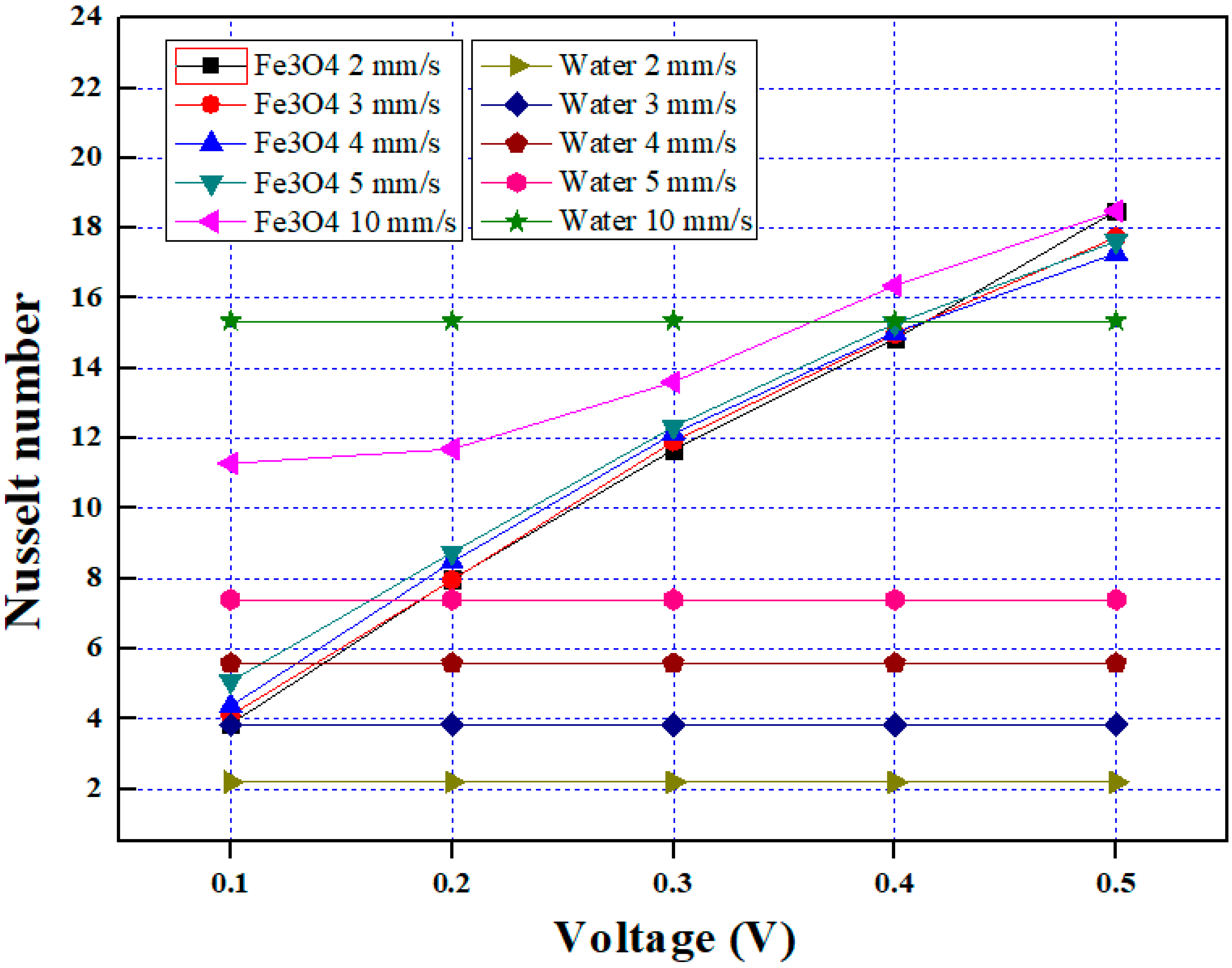
The effect of water and ferrofluid cooling with various conditions of inlet velocity and voltage on the Nusselt number is presented in
Figure 9. The lower inverter temperature indicates higher dissipation of heat from the traction inverter to coolant, which results in a higher Nusselt number. The lower temperature of the traction inverter is noticed in the case of ferrofluid cooling compared to water cooling, hence, the Nusselt number is superior for ferrofluid cooling compared to water cooling under the same conditions. The Nusselt number for water cooling remains constant with changes in voltage because of constant velocity and inverter temperature However, with an increase in inlet velocity, the inverter temperature decreases for water cooling, which shows an increase in the Nusselt number. The Nusselt numbers of 2.20, 3.83, 5.59, 7.40, and 15.35 are evaluated in the case of water cooling for inlet velocities of 2 mm/s, 3 mm/s, 4 mm/s, 5 mm/s, and 10 mm/s, respectively. The Nusselt number increases with an increase in voltage for ferrofluid cooling due to an improved convection effect with use of an MHD pump. However, the impact of inlet velocity on the Nusselt number in the case of ferrofluid cooling is significant at lower voltage and significance decreases with an increase in voltage. Therefore, in the case of ferrofluid cooling, the increasing rate in the Nusselt number with inlet velocity is higher at lower voltage. In the case of ferrofluid cooling, with an increase in voltage from 0.1 V to 0.5 V, the Nusselt number increases from 3.86 to 18.49 at an inlet velocity of 2 mm/s, 4.11 to 17.74 at an inlet velocity of 3 mm/s, 4.36 to 17.28 at an inlet velocity of 4 mm/s, 5.07 to 17.62 at an inlet velocity of 5 mm/s, and 11.29 to 18.49 at an inlet velocity of 10 mm/s, respectively.
3.3. Effect of Electromagnetic Parameters
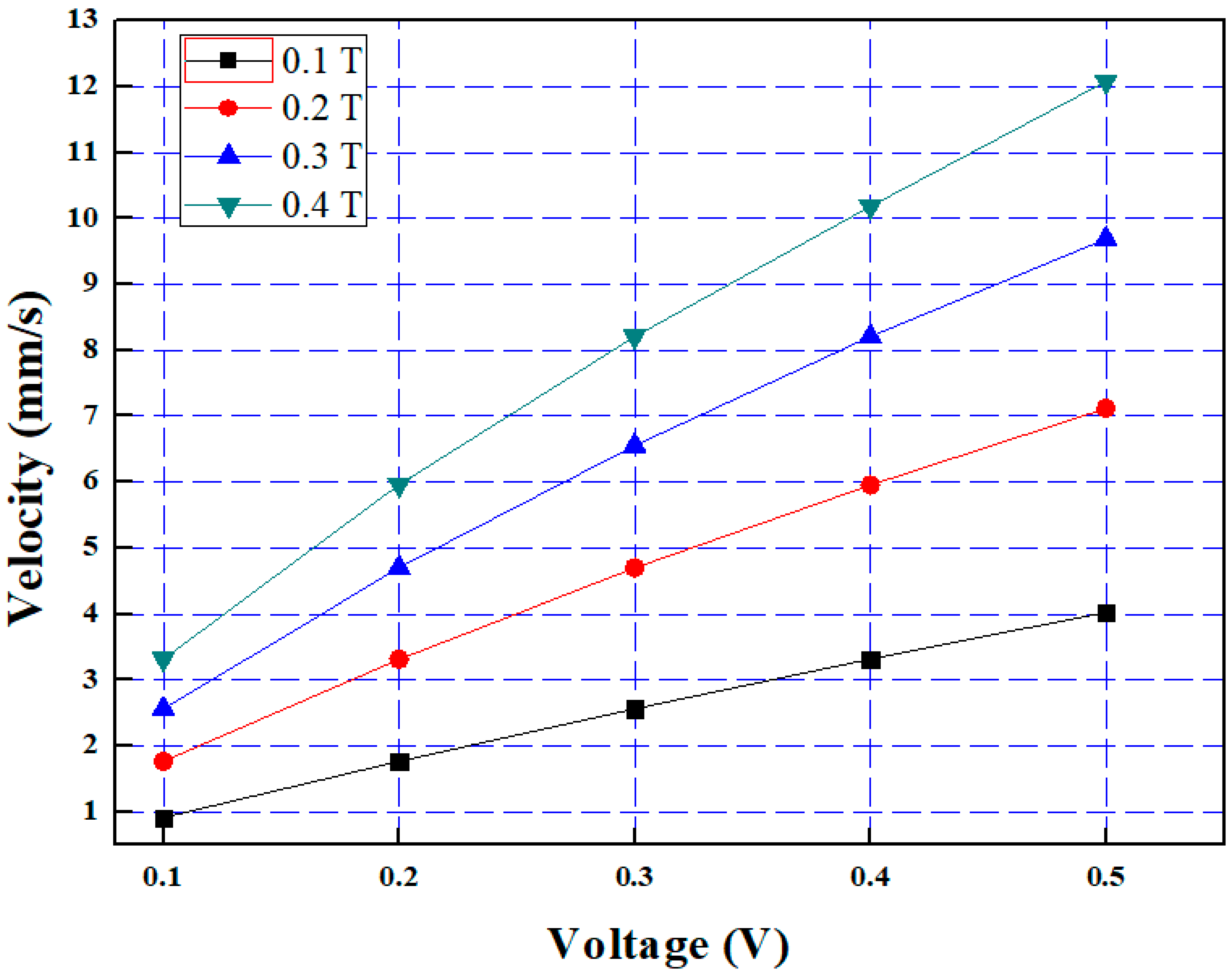
Figure 10 shows the effect of magnetic field intensity and voltage on velocity in the cooling channel. The Lorentz force using the MHD pump is generated in a perpendicular direction to the applied magnetic field and voltage directions which drives the coolant in the cooling channel. The ferrofluid depicts the quality of self-circulation under the influence of magnetic field intensity and voltage, hence, velocity in the cooling channel due to the MHD pump is generated for ferrofluid coolant. The self-circulation performance of ferrofluid using the MHD pump improves with a rise in voltage and magnetic field intensity, which results in a linear increase in velocity of ferrofluid coolant with an increase in voltage and magnetic field intensity. Therefore, the intensity of coolant mixing is high at a higher voltage and magnetic field intensity, which results in higher velocity. The higher velocity indicates improvement in forced convection, which results in enhanced heat transfer performance of ferrofluid cooling. In the case of water, the velocity generated by the MHD pump is zero, owing to the absence of self-circulating characteristics under the influence of a magnetic field and voltage. The increase rate in velocity with increase in voltage is superior at a higher magnetic intensity and increasing rate becomes narrow as the magnetic field intensity decreases. With an increase in voltage from 0.1 V to 0.5 V, the velocity increases from 0.92 mm/s to 4.03 mm/s in the case of 0.1 T, 1.77 mm/s to 7.12 mm/s in the case of 0.2 T, 2.56 mm/s to 9.69 mm/s in the case of 0.3 T and 3.32 mm/s to 12.08 mm/s in the case of 0.4 T, respectively.
The variation in the inverter maximum temperature for various conditions of magnetic field intensity and voltage in the case of water and ferrofluid cooling is shown in
Figure 11. In the case of water cooling, the traction inverter temperature is 354 °C, which is significantly higher than the maximum allowable temperature for the failure of a traction inverter. Furthermore, the change in magnetic field intensity and voltage has no influence on the inverter maximum temperature in the case of water cooling because of the absence of magnetic properties which help to create the self-circulation effect using the MHD pump in the case of water cooling. Despite of the presence of the MHD pump, the water cannot be circulated and remained stagnant, which creates the natural convection cooling in the case of water, thus, the inverter maximum temperature is high for water cooling. The ferrofluid enables the excellent magnetic and electrical properties which create the self-circulation of ferrofluid using the MHD pump under various conditions of magnetic field intensity and voltage. With the rise in magnetic field intensity and voltage, the MHD pump power increases, which creates a higher intensity of force circulation effect in ferrofluid cooling. Therefore, in the case of ferrofluid cooling, the inverter maximum temperature decreases with an increase in magnetic field intensity and voltage. Furthermore, the heat transfer properties of ferrofluid are superior compared to water. The improvement in the forced circulation effect and heat transfer properties result in higher dissipation of heat from the traction inverter to ferrofluid and thus the lower inverter maximum temperature compared to water cooling. The decrease in the steepness curve of the inverter maximum temperature with an increase in voltage is higher in the case of lower magnetic field intensity. However, the lowest inverter maximum temperature is evaluated at a higher magnetic field intensity and higher voltage owing to the superior MHD pump effect. At magnetic field intensity of 0.1 T, 0.2 T, 0.3 T, and 0.4 T, the inverter maximum temperature decreases from 171.03 °C to 58.11 °C, 100.67 °C to 44.08 °C, 76.39 °C to 37.67 °C, and 64.89 °C to 32 °C, respectively, when the voltage increases from 0.1 V to 0.5 V.
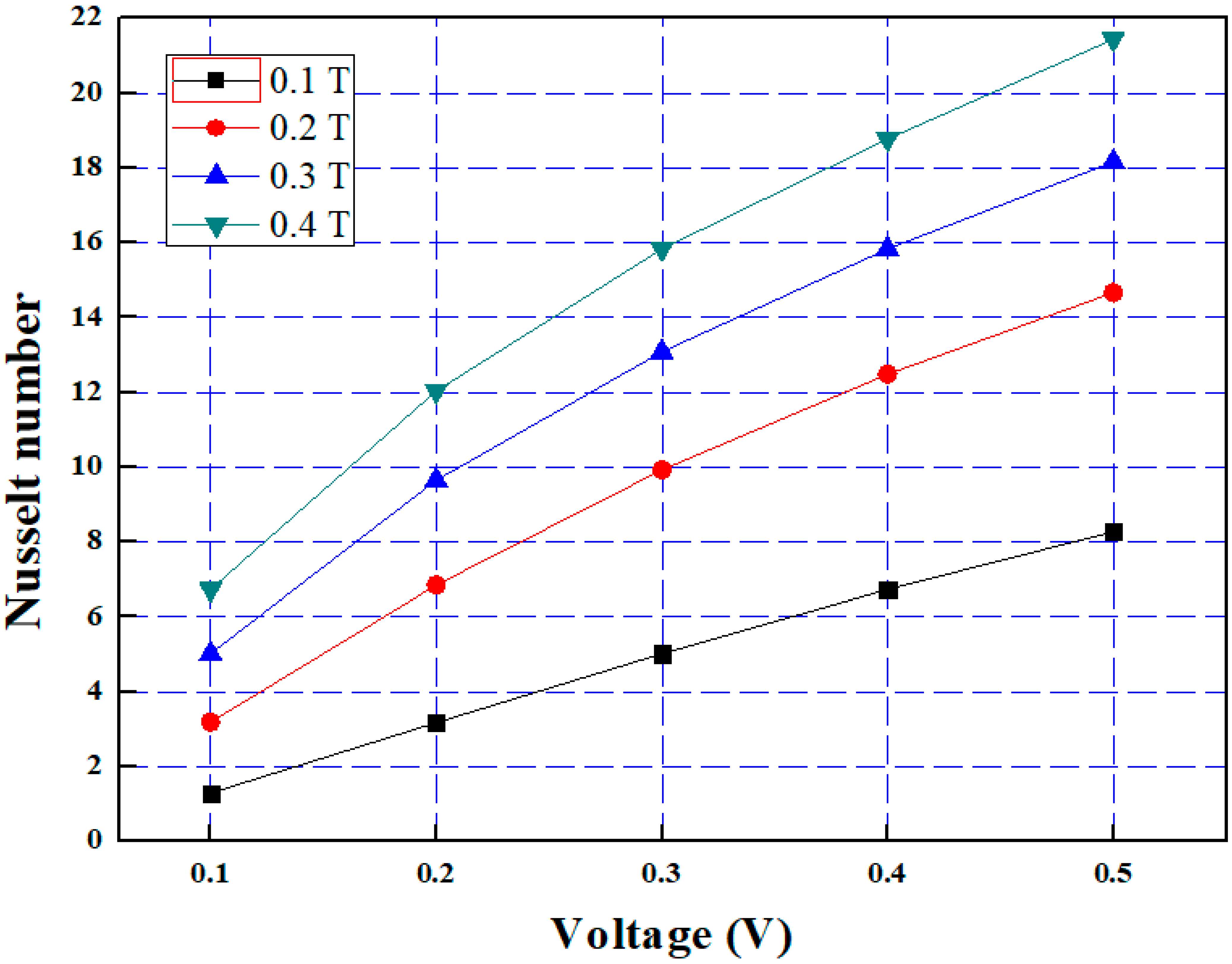
The behavior of the Nusselt number for ferrofluid cooling under various conditions of magnetic field intensity and voltage is depicted in
Figure 12. The lower values of the inverter maximum temperature indicate that a higher amount of heat is dissipated from the traction inverter to ferrofluid, which means the heat transfer coefficient and Nusselt number are superior. The higher heat transfer rate from the traction inverter to ferrofluid improves the heat transfer coefficient, which results in a higher Nusselt number. The Nusselt number increases with an increase in magnetic field intensity and voltage such that the highest values of the Nusselt number are reflected at higher values of magnetic field intensity and voltage because the higher values of the magnetic field intensity and voltage show lower values of the inverter maximum temperature. The increase rate in the Nusselt number with increase in voltage is the maximum at a higher value of the magnetic field intensity because the velocity improves significantly with a rise in voltage at a higher magnetic field intensity. The higher value of velocity gives a higher degree of forced convection, which is reflected as a higher heat dissipation rate and Nusselt number. Therefore, the variation trend of the Nusselt number with voltage and magnetic field intensity is similar to velocity. The Nusselt number increases from 1.29 to 8.27 in the case of 0.1 T, 3.19 to 14.66 in the case of 0.2 T, 5.02 to 18.16 in the case of 0.3 T and 6.73 to 21.43 in the case of 0.4 T with an increase in voltage from 0.1 V to 0.5 V.
The cooling performance of a traction inverter using an MHD pump-based cooling system is enhanced with an increase in magnetic field intensity and voltage. However, the values of magnetic field intensity and voltage could be optimized to achieve the desired cooling performance of the traction inverter for improving the overall performance of EVs. For example, the combination of magnetic field intensity and voltage with corresponding values of 0.1 T and 0.5 V shows the inverter maximum temperature of 58.11 °C, however, that of 0.4 T and 0.5 V shows the inverter maximum temperature of 32 °C. Therefore, the trade-off between the magnetic field intensity and voltage values could be adjusted based on the demand on the traction inverter under various operating conditions. The MHD pump with optimized parameters could be effectively used in combination with a conventional pump. This will help to reduce the power consumption with desired cooling performance for the thermal management of the traction inverter to achieve extended driving range and efficiency of electric vehicles.
Apart from electromagnetic parameters, the ferrofluid distribution in MHD pump-based cooling systems is significantly affected by magnetic field patterns. In our previous work, the heat transfer characteristics of ferrofluid for cooling of power electronics in EVs were investigated considering no magnetic field pattern and I-, L-, and T-shaped magnetic field patterns. For no magnetic field pattern, the heat gets accumulated near the heat source and heat dissipation follows the paths of I, L, and T based on corresponding magnetic field patterns. The heat flow rate and direction to dissipate the heat from power electronics to the cooling source using ferrofluid could be optimized based on criteria of lowest thermal resistance [
25]. The findings from the previous study about the ferrofluid behavior under the influence of various magnetic field patterns could be referenced to design MHD pump-based cooling systems for thermal management of EV traction inverters with lower power consumption (based on lower thermal and flow resistances from heat source to heat sink).
3.4. Effect of Ferrofluid Volume Fraction
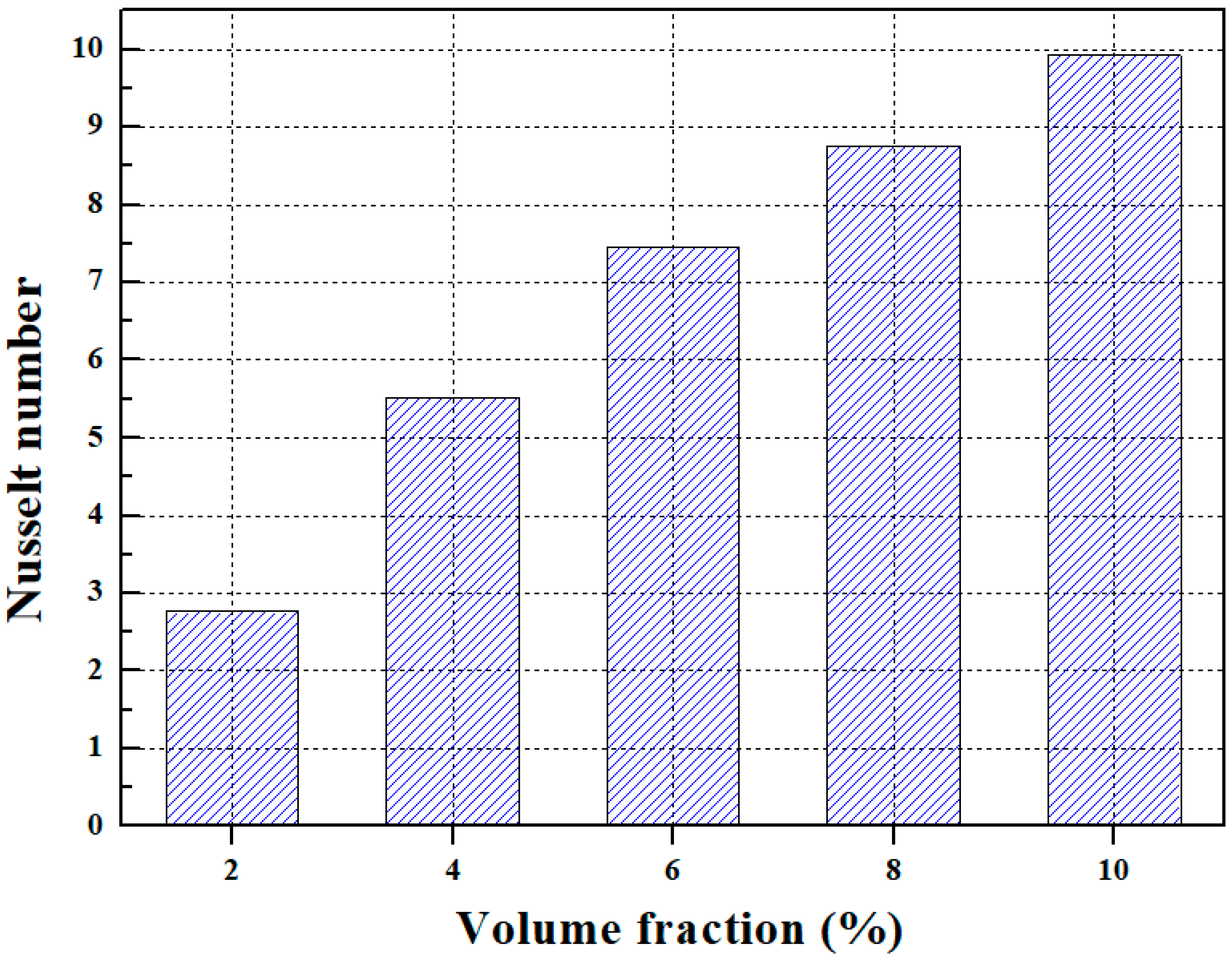
The effect of ferrofluid volume fraction on the Nusselt number is depicted in
Figure 13. The cooling performance of ferrofluid can be expressed as its ability to absorb the heat and transfer it away from traction inverter. The Nusselt number indicates the heat removal rate from traction inverter to ferrofluid using an MHD pump-based cooling system. The nanoparticles are able to absorb more heat and transfer it away from the source more efficiently as their concentrations increase, therefore, the higher volume fraction of nanoparticles in the ferrofluid shows the enhanced cooling performance. Furthermore, the heat dissipation performance of ferrofluid improves with the rise in volume fraction because the thermophysical properties of ferrofluid improve with an increase in the volume fraction of nanoparticles. Therefore, it has been observed that ferrofluid with a volume fraction of 10% shows a superior cooling performance for traction inverters. The Nusselt numbers of 2.76, 5.52, 7.45, 8.76, and 9.92 are evaluated for ferrofluid volume fractions of 2%, 4%, 6%, 8%, and 10%, respectively.
The present work demonstrates the feasibility of MHD pump-based cooling systems to maintain the desired cooling performance of traction inverters by varying key influencing parameters for small capacity E-mobility applications (Small-capacity EVs, electric tricycle or motorcycle, etc.). It is important to note that the cooling performance of an MHD pump-based cooling system for a traction inverter can also be influenced by other factors, such as the size and shape of nanoparticles, type of nanoparticles, magnetic field patterns, temperature, and flow rate of the coolant. These factors can affect the ability of coolant to absorb and transfer heat and should be considered when designing and optimizing a cooling system for traction inverters in EVs. The future work will be focused on evaluating the cooling performance of MHD pump-based cooling systems, considering aforementioned parameters for the thermal management of traction inverters under actual operating conditions of EVs with higher power capacity.


