
Analysis of the Factors Influencing the Trailing Infrared Characteristics of Underwater Vehicles under Surge Conditions Using the Orthogonal Method
Abstract
:1. Introduction
2. Basic Theory
2.1. Numerical Calculation Theory of Fluid Heat Transfer
- (1)
- The mass conservation formula
- (2)
- Equation for momentum conservation [16]
- (3)
- Equation for energy conservation [16]
2.2. Theory of Sea Surface Infrared Calculations
- (1)
- Radiation from the sea surface target itself
- (2)
- Reflection of sky radiation by sea surface targets
- (4)
- Reflection of sea surface radiation by sea surface targets
- (5)
- Infrared radiation characteristics model of a sea surface target
3. Experimental Design
3.1. Theory of Sea Surface Infrared Calculations
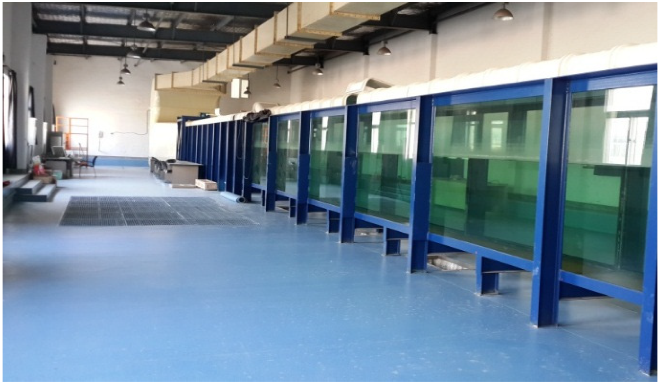
- (1)
- Device for simulating underwater waves
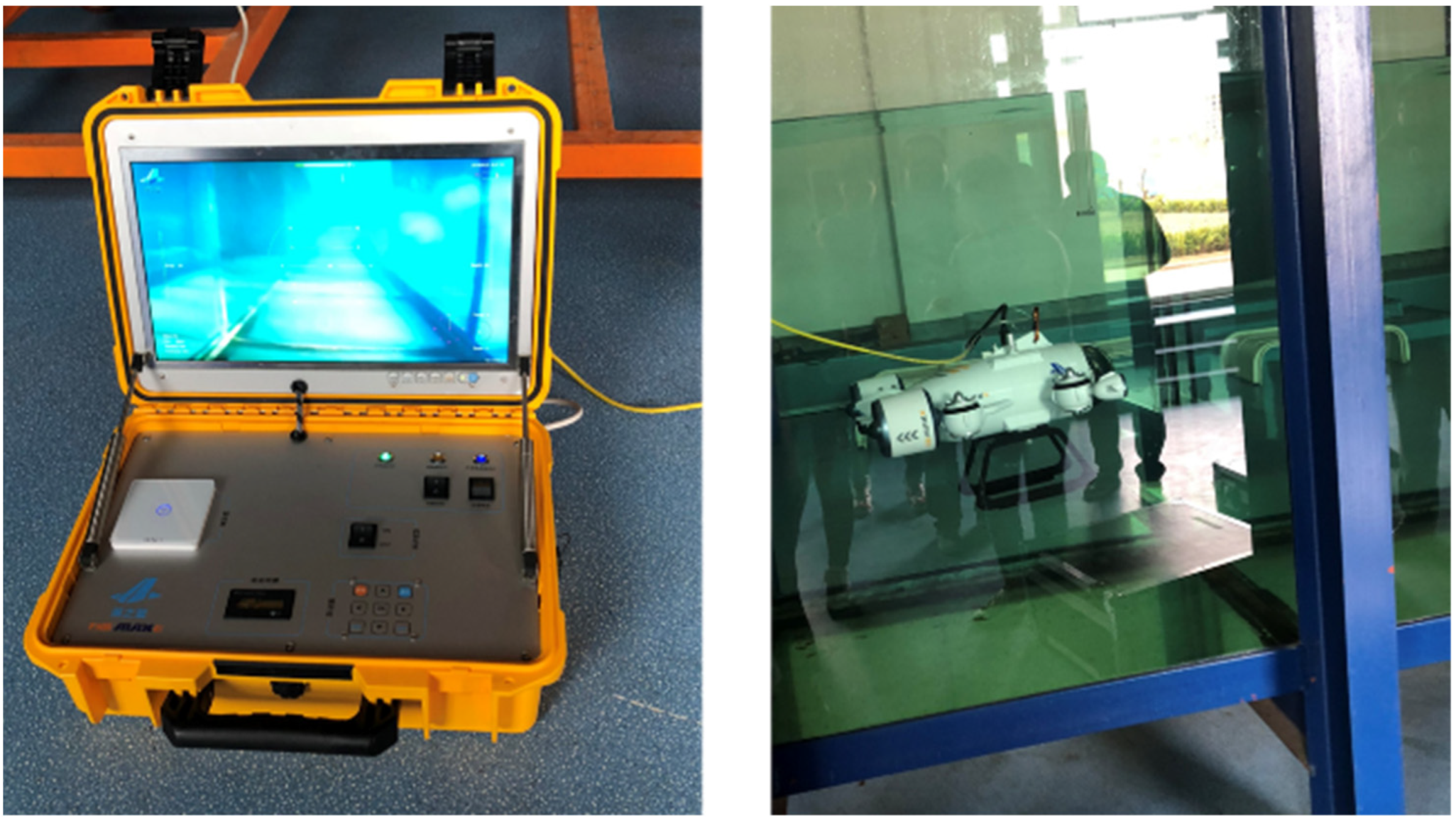
- (2)
- Underwater vehicle
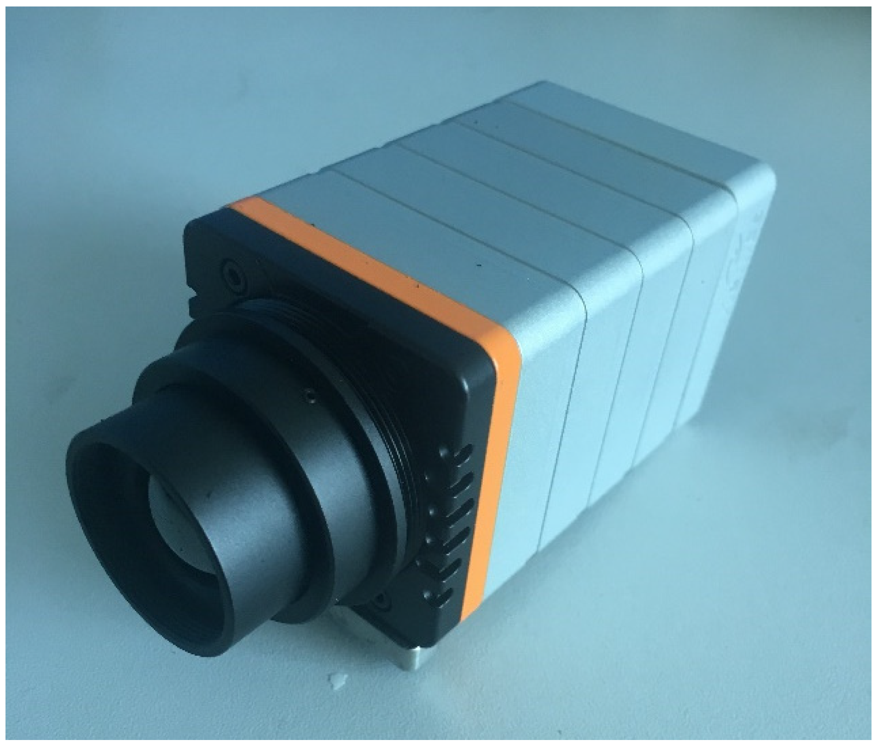
- (3)
- Infrared camera parameters
3.2. Theory of Sea Surface Infrared Calculations
4. Experimental Results and Analysis
4.1. One-Factor Experimental Analysis
4.2. Orthogonal Test Analysis
5. Conclusions
Author Contributions
Funding
Institutional Review Board Statement
Informed Consent Statement
Data Availability Statement
Conflicts of Interest
References
- Fang, K.; Ma, C. Uniform Experiment and Orthogonal Experiment; Science Press: Beijing, China, 2001; pp. 35–77. [Google Scholar]
- Wang, J.; Guo, Y.; Gu, J. The theoretical and trial study of thermal wake in the infrared detection of submarines. Laser Infrared 2002, 32, 159–162. [Google Scholar]
- Fu, Q.; Luo, K.; Song, Y.; Zhang, M.; Zhang, S.; Zhan, J.; Duan, J.; Li, Y. Study of Sea Fog Environment Polarization Transmission Characteristics. Appl. Sci. 2022, 12, 8892. [Google Scholar] [CrossRef]
- Gu, J.; Zhang, Z.; Zheng, X. Calculation model and experiment study of the thermal wake characteristics of submarine. Torpedo Technol. 2003, 11, 46–50. [Google Scholar]
- Zhang, X.; Zhang, Y.; Zhao, H.; Deng, H.Y.; Wang, Y. Research on Long Wave Infrared Imaging of Sea Target. In Proceedings of the Eighth Symposium on Novel Photoelectronic Detection Technology and Applications, Kunming, China, 9–11 November 2021; Volume 12169, pp. 54–63. [Google Scholar]
- Yang, L.; Hua, S.; Du, X. The buoyant trajectory of thermal wake after underwater vehicle in stable stratified fluid. J. Eng. Thermophys. 1991, 12, 74–77. [Google Scholar]
- Lei, D.; Chen, B. Theoretical analysis of buoyant process of bubbly thermal wake behind body going underwater. J. Therm. Sci. Technol. 2008, 7, 203–210. [Google Scholar]
- Jian, Z.; Xuan, C.; Li, Y. Study of temperature characteristic of cooling water discharged by underwater vehicle. J. Ship Mech. 2009, 13, 533–539. [Google Scholar]
- Chen, B.; Lei, D.; Wu, M.; Xie, Z.; Chen, S.; Zhang, S. Numerical simulation on the buoyant laws and the cold-thermal surface features of the wake behind a moving underwater body. Infrared Laser Eng. 2012, 41, 1140–1146. [Google Scholar]
- Zhang, X.; Guo, L.; Hu, R.; Chang, W. Buoyancy diffusion law and ocean-surface temperature characteristic of submarine thermal wake. Infrared Technol. 2016, 38, 678–682. [Google Scholar]
- Yang, L.; Chen, X.; Chang, S.; Xu, E.; Wang, X.; Wang, Y.; Zhao, X.; Du, Y.; Kou, W.; Fan, C. Infrared Imaging Simulation and Detection of Ship Wake. In Proceedings of the AOPC 2015: Optical and Optoelectronic Sensing and Imaging Technology, Beijing, China, 5–7 May 2015; p. 96741F. [Google Scholar]
- Kou, W.; Chen, X.; Yang, L.; Jin, F.Y. Evaluation of wake detection probability of underwater vehicle by IR. Proc. SPIE 2016, 157, 1–7. [Google Scholar]
- Yang, C.Y.; Cao, L.H.; Zhang, J.P.; Lu, M. Infrared Signature Measurement of Targets Accounting for Atmospheric Attenuation. In Proceedings of the 2010 International Conference on Computer, Mechatronics, Control and Electronic Engineering, Changchun, China, 24–26 August 2010; Volume 4, pp. 301–303. [Google Scholar]
- Liu, T.L.; Guo, Z.M. Analysis of wave spectrum for submerged bodies moving near the free surface. Ocean. Eng. 2013, 58, 239–251. [Google Scholar] [CrossRef]
- Brucker, K.A.; Sarkar, S. A comparative study of self-propelled and towed wakes in a stratified fluid. J. Fluid Mech. 2010, 652, 373–404. [Google Scholar] [CrossRef] [Green Version]
- Liang, S.; Strahler, A.H. Four-stream solution for atmospheric radiative transfer over a non-Lambertian surface. Appl. Opt. 1994, 33, 5745–5753. [Google Scholar] [CrossRef] [PubMed]
- Huo, Y. Study of the Scattering Properties of Surface Vessels in Relation to the Solar Brilliant Band. Ph.D. Thesis, Xidian University, Xi’an, China, 2020. [Google Scholar] [CrossRef]
- Li, D.; Yang, L.; Zhang, S. Study on the influence of coating emissivity on the infrared characteristics of sailing ships. Infrared Technol. 2010, 32, 5. [Google Scholar]
- Chen, X. Analysis of Sea Surface Infrared Characteristics under the Coupling Effect of Hydrodynamic Wake and Thermal Wake of a Submarine. Ph.D. Thesis, Nanjing University of Science and Technology, Nanjing, China, 2018. [Google Scholar]
- Feng, Y. Study of Infrared Radiation Characteristics of Sea Surface Targets. Ph.D. Thesis, Xidian University, Xi’an, China, 2009. [Google Scholar]


| Camera Models | Xenics-Gobi 640-GigE |
|---|---|
| Infrared Band | 8 μm~14 μm |
| NETD | 55 mk |
| Depth/cm | 20 | 30 | 40 | 50 | 60 | 70 |
| ΔT/°C | 0.76 | 0.61 | 0.52 | 0.33 | 0.30 | 0.24 |
| Test Serial Number | Column Number | ||||
|---|---|---|---|---|---|
| 1 | 2 | 3 | 4 | 5 | |
| 1 | 1 | 1 | 1 | 1 | 1 |
| Level | Depth (A) | Surge Height (B) |
|---|---|---|
| 1 | 30 cm | 0 cm |
| 2 | 40 cm | 0.3 cm |
| 3 | 50 cm | 0.5 cm |
| Column Number | 1 | 2 | 3 |
| Factors | A | B | AB |
| 2 | 1 | 1 | 1 | 2 | 2 |
| 3 | 1 | 2 | 2 | 1 | 2 |
| 4 | 1 | 2 | 2 | 2 | 1 |
| 5 | 2 | 1 | 2 | 1 | 2 |
| 6 | 2 | 1 | 2 | 2 | 1 |
| 7 | 2 | 2 | 1 | 1 | 1 |
| 8 | 2 | 2 | 1 | 2 | 2 |
| 8 | 2 | 2 | 1 | 2 | 2 |
| A | B | AB | Temperature Difference (°C) | |
|---|---|---|---|---|
| 1 | 1 | 1 | 1 | 0.61 |
| 2 | 1 | 3 | 3 | 0.47 |
| 3 | 2 | 3 | 2 | 0.38 |
| 4 | 2 | 2 | 2 | 0.26 |
| 5 | 3 | 2 | 3 | 0.14 |
| 6 | 3 | 1 | 1 | 0.33 |
| K1 | 0.54 | 0.47 | 0.47 | |
| K2 | 0.32 | 0.2 | 0.32 | |
| K3 | 0.235 | 0.425 | 0.31 | |
| R | 0.305 | 0.225 | 0.16 |
| Depth | Surge Height | Trailing Temperature Difference | |
|---|---|---|---|
| Depth | 1 | −0.250 0.633 | −0.833 * 0.040 |
| Surge Height | 1 | −0.123 0.817 | |
| Trailing Temperature Difference | 1 |
Disclaimer/Publisher’s Note: The statements, opinions and data contained in all publications are solely those of the individual author(s) and contributor(s) and not of MDPI and/or the editor(s). MDPI and/or the editor(s) disclaim responsibility for any injury to people or property resulting from any ideas, methods, instructions or products referred to in the content. |
© 2023 by the authors. Licensee MDPI, Basel, Switzerland. This article is an open access article distributed under the terms and conditions of the Creative Commons Attribution (CC BY) license (https://creativecommons.org/licenses/by/4.0/).
Share and Cite
Zheng, S.; Li, G.; Fu, Q.; Luo, K.; Shi, H.; Yang, D.; Li, Y. Analysis of the Factors Influencing the Trailing Infrared Characteristics of Underwater Vehicles under Surge Conditions Using the Orthogonal Method. Appl. Sci. 2023, 13, 3234. https://doi.org/10.3390/app13053234
Zheng S, Li G, Fu Q, Luo K, Shi H, Yang D, Li Y. Analysis of the Factors Influencing the Trailing Infrared Characteristics of Underwater Vehicles under Surge Conditions Using the Orthogonal Method. Applied Sciences. 2023; 13(5):3234. https://doi.org/10.3390/app13053234
Chicago/Turabian StyleZheng, Shuang, Guanlin Li, Qiang Fu, Kaiming Luo, Haodong Shi, Di Yang, and Yingchao Li. 2023. "Analysis of the Factors Influencing the Trailing Infrared Characteristics of Underwater Vehicles under Surge Conditions Using the Orthogonal Method" Applied Sciences 13, no. 5: 3234. https://doi.org/10.3390/app13053234