Article

Shielding Grounding Optimization Method for Spaceborne Multi-Cable

1
Key Laboratory of Infrared System Detection and Imaging Technologies, Shanghai Institute of Technical Physics, Chinese Academy of Sciences, Shanghai 200083, China
2
University of Chinese Academy of Sciences, Beijing 100049, China
3
Shanghai Aerospace Electronic Technology Institute, Shanghai 201109, China
*
Author to whom correspondence should be addressed.
Appl. Sci. 2023, 13(6), 3389; https://doi.org/10.3390/app13063389
Submission received: 12 February 2023 / Revised: 2 March 2023 / Accepted: 6 March 2023 / Published: 7 March 2023
(This article belongs to the Section Electrical, Electronics and Communications Engineering)

Abstract

:
The coupling relationship between space electronics systems is complex, and the signals of optoelectronic load cables are susceptible to interference, especially the early anomalous weak signals on a ground surface used for immediate remote sensing, which are more susceptible to coupling interference between cables. Ensuring a good grounding state for the cable shield is vital for reducing the interference suffered by cables and increasing the electromagnetic compatibility of the system. In this paper, we propose a shielding grounding optimization method for a spaceborne multi-cable shield, including a cable model and parameter extremization and parameter scanning simulation performed using CST, data processing and truth table transformation conducted using MATLAB, and logic expression extraction carried out using Multisim. The method can sort and classify the shielding effects of all the grounding states of multi-cable shields in batches, and ultimately output logical expressions specifying the mapping relationship between the shield grounding state and shielding effect, allowing the optimal shield grounding state to be quickly identified. Finally, the method was applied to a satellite-borne scanning mirror drive control system, and the effectiveness and accuracy of the method were verified by experimental tests.

1. Introduction

The limited space inside a spacecraft payload, the complex connection relationships between the electronics systems, the large number of cables, and the different sizes and frequencies of the signals transmitted by each cable make the cable signals and related signals vulnerable to interference. Remote sensing is being developed to enable immediate and early prediction [1]. The surface anomaly signals are often weak [2] and are more easily obscured by interference between cables, making the system unable to achieve effective detection; a significant reduction in the impact of signal interference between load cables has become the focus of remote sensing developmental research [3]. To reduce interference, the cable is usually wrapped in a metal shield. The grounding method employed for the shield greatly influences the shielding effect; a shield with an inappropriate grounding method will not exhibit effective shielding and may even increase interference in the inner core of the cable. For example, when a shield is grounded at the end of the signal transmitter only, it can shield the electric field but not the magnetic field [4], whereas when both ends of the shield are grounded, if there is a potential difference between the grounding points, interference currents will occur on the shield, which in turn induce noise voltages in the inner core of the cable [5]. Many researchers have also analyzed and discussed the effects of different shield grounding methods on the shielding effect. Zhou et al. studied the influence of different cable shielding methods on shielding against lightning surge currents. By grounding both ends of the outer shielding and one end of the inner shielding, the induced current of the cable was reduced to about 5% [6]. Yaglidere’s research showed that a poor shield grounding state could reduce the shielding performance by more than 30 dB [7]. Therefore, choosing the best cable shield grounding state is important for improving the shielding effect, reducing the interference received by the cable, and increasing the electromagnetic compatibility of aerospace electronics systems.
However, the current studies on cable shielding and grounding have the following limitations. Firstly, most of the existing studies on shielding effects under different shielding grounding conditions have focused on instances where the number of cables is small, and there is usually only one cable that is subjected to interference and one interfering cable [8,9]. The research on interference between multiple cables is often limited to theoretical calculations and modeling simulations, lacking experimental verification [10,11]. Secondly, the existing studies usually derive and solve the transfer impedance or shielding efficiency of the cable shield using an electromagnetic field analytical formula, which is complicated [12,13]. In practice, it is difficult to accurately describe the coupling relationship between so many cables using electromagnetic field analysis. Although some researchers [14] have simply analyzed the mechanism by which the shield protects against an electromagnetic field by using the parasitic inductance and parasitic capacitance from the topological structure of the circuit, and also proposed measures to suppress interference, they are limited to a single cable, and the circuit topology of the coupling relationship between multiple cables becomes very difficult to describe. Thirdly, standard test methods, such as the injection method [15] and triaxial test method, are generally used for experimental verification in existing studies [16,17], which makes it difficult to build cost-effective experimental platforms. Moreover, these standard testing methods explore the transfer impedance of a single shield; therefore, it is difficult to measure the shielding efficiency when multiple cables interact. In addition, the number of grounding states of the cable shield exponentially increases with the number of cables, and it is very time-consuming to test all the grounding states one by one. In summary, there is no method for determining the optimal grounding state for multiple cable shielding.
In this study, the shield grounding optimization of a spaceborne multi-cable was studied. The paper is organized as follows. The Section 1 is the Introduction. The Section 2 introduces the overall process of the grounding optimization method for a spaceborne multi-cable shield and explains each step of the method, respectively. Additionally, this work is compared with related work to illustrate the advantages and disadvantages of the proposed methods. In the Section 3, an experimental test of the actual satellite-borne scanning mirror drive control system is described, and the obtained angle accuracy of the scanning mirror under the grounding state for all the cable shields is described. In the Section 4, the application of the method to the actual control system and a comparison with the measured results are presented. The Section 5 summarizes this paper.

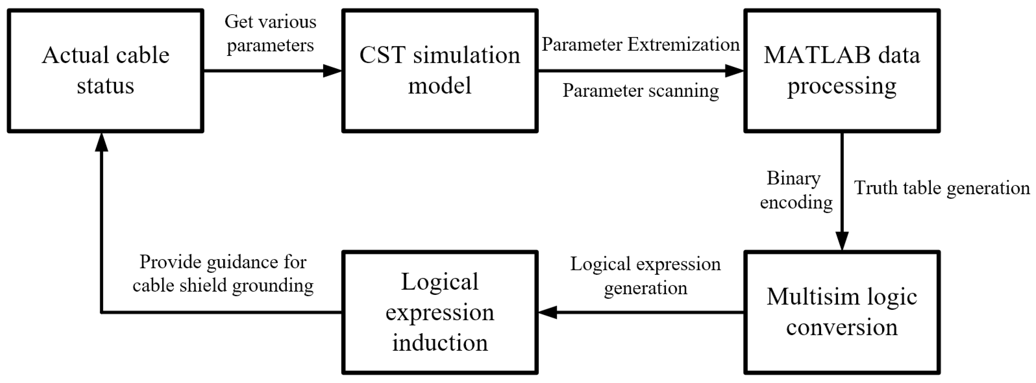
2. Shielding Grounding Optimization Method

Figure 1 shows the overall process of the shield grounding optimization method. The first step was to obtain relevant parameters, such as the number, lengths, and position relationships of cables according to the actual state of the cables, to establish the CST (Computer Simulation Technology simulation software) simulation model. The simulation results for all the shield grounding states were obtained by means of parameter extremization and parameter scanning simulation. The second step was to use MATLAB to encode the simulation results in binary form and generate the truth table. In the third step, the logic conversion module of Multisim was used to extract and simplify the logical expression of the truth table. The output logical expression indicated the corresponding relationship between the grounding state of the shield and the shielding effect. The fourth step was to analyze and summarize the logical expression used to guide the termination of the cable shield. The following is a detailed explanation of each step in the method.

2.1. CST Modeling and Simulation

As shown in Figure 2, the number of cables was set as i , denoting them as C 1 , C 2 ,   ,   C i . The cable lengths are L 1 , L 2 ,   ,   L i . The vertical heights of the cable from the reference plane are H 1 , H 2 ,   ,   H i , respectively. D 12 represents the horizontal distance between C 1 and C 2 , etc. Each cable was wrapped in shielding. The two ends of the shield were grounded through the resistance. The side near the signal-sending end is called the near end, and the subscript is N . The grounding resistance of the near end is R 1 N , R 2 N ,   ,   R i N . The side near the receiving end of the signal is called the far end, and the subscript is F . The grounding resistance of the far end is R 1 F , R 2 F ,   ,   R i F . Actual cables may be bent and stacked, which greatly increases the difficulty of modeling. In addition, the positions and states of cables may not be identical each time during actual tests. Therefore, modeling a cable in strict accordance with a cable shape is not universal and is not important. In addition, the bending and stacking of cables may affect the signals inside the cables, which may impact subsequent test results and lead to a misjudgment of the shielding effect. Therefore, this study only considered the simplest parallel cables and eliminated the influence of the bending and stacking of cables to analyze the shielding effect of the shield under different grounding states.
In the actual electronics system, the grounding status of the cable shield varies, including double-terminal grounding, ungrounded, single-terminal grounding at the near end, and single-terminal grounding at the far end. Therefore, it was necessary to parameterize each physical quantity shown in Figure 2, so that all the ground states could be traversed using parameter scanning. However, there are two special cases in the parameterization process, one of which is that, when the shield of an actual cable is not grounded, according to the traditional modeling method, the grounding resistance needs to be removed and the simulation needs to be run again, which undoubtedly increases the manual operation cost and time complexity in the case of multiple cables and multiple states. Therefore, this paper proposes the processing method of parameter extremization, i.e., increasing R i N and R i F to certain values to simulate the cable state as ungrounded, which avoids frequent modifications to the model and greatly facilitates the automatic parameter scanning process of CST. The other issue is that, if the CST requirements for some of the model’s physical size parameters mean that they must be set greater than 0, the model will not be able to set the shield thickness to 0 mm to simulate an actual cable without a shield. It is also necessary to address the extremes of the shield thickness parameter, i.e., when the thickness is reduced to a certain value to simulate an actual cable without a shield. However, such parameter extremization processing does not represent a real state, and would therefore cause errors. Therefore, it was necessary to further judge the degree of parameter extremization to ensure that the error between the result and the real state was within an acceptable range. The following is an example of resistance parameter extremization.
In the CST example model shown in Figure 3, the simplest case was considered, where the interfering line C 1 is a single cable, and the interfered line C 2 is a coaxial cable, D 12 = 5   cm : H 1 = H 2 = 5   cm . A sinusoidal voltage excitation of different frequencies with an amplitude of 30 V was applied in C 1 , R 2 N was increased, and the peak magnitude of the disturbance voltage in C 2 was simulated. Finally, the grounding resistance of C 2 was removed, and the simulation result was used as a benchmark for comparison. The error obtained by subtracting it from the simulation result after parameter extremization is shown in Figure 4.
Figure 4 shows that, the larger the resistance value of R 2 N , the smaller the error between the simulation results for parameter extremization processing and the simulation results for an ungrounded shield. When R 2 N is taken to be 10 8   Ω, the error drops by an order of magnitude of 10 8 , which allows the state of an ungrounded shield to be completely simulated. In addition, it can be seen from the graph that, the lower the frequency of the interference source, the slower the decrease in the error curve of parameter extremization. This means that, at low frequencies, greater resistance and a deeper degree of parameter extremization are required to simulate the state of an ungrounded shield. The reason is that the low-frequency signal interferes less with the line that is subjected to interference compared to the high-frequency signal; after the double-ended well-grounded shield (a smaller grounding resistance means better grounding) was introduced, the signal improvement amplitude was also small, and when the signal frequency increased, the well-grounded shield caused a drastic improvement, so the curve decreased faster.
After the parameter extremization was complete, CST could be used to perform a full-parameter scan simulation of the interference voltage of the target cable, and the interference voltage was recorded as U . The final output in terms of the simulation data is shown in Table 1. The method has good scalability, and the “other parameters” alluded to in Table 1 could be the shielding material, thickness, incidence angle, intensity of external radiation sources, cable spacing, etc., according to any additional needs. This paper only focuses on grounding resistance. Table 1 shows i cables, and each cable shield has four possible grounding states: R i N = R i F = 0 Ω for the cable C i double-ended ground shield; R i N = R i F = 10 8   Ω for the ungrounded shield; R i N = 0 ,   R i F = 10 8   Ω for the grounded shield at the near end; and R i N = 10 8 ,   R i F = 0   Ω for the shield grounded at the far end. Therefore, a total of 4 i kinds of permutations are possible.
The CST model shown in Figure 3 is used as an example to illustrate the results of the parameter extremization and parameter scans, as shown in Table 2. When additional parameters were introduced, the number of states exponentially increased, which required MATLAB to process large amounts of data.

2.2. MATLAB Transformation Truth Table

The CST simulation results were automatically judged and binary-coded using MATLAB and ultimately converted into a truth table, as shown in Table 3. The left input of the truth table is the state of each variable of the CST model: “1” means the resistance is 0 Ω, i.e., the shield is grounded on this side; “0” means the resistance is 10 8   Ω, i.e., the shield is not grounded on this side. The interference voltages obtained from the simulation of 4 i cases are sorted from small to large and divided into n voltage levels, i.e., the right-hand side of the truth table output Y 1 Y 2 Y n , corresponding to an n shielding effect. The smaller the subscript number of Y , the smaller the interference voltage induced on the target cable and the better the shielding effect. The reason for this grading is that, in 4 i cases, there are several cases with close interference voltage results, i.e., the simulation results will be graded, resulting in n     4 i .
For each row of the truth table, only one of the bits in Y 1 Y 2 Y n is “1”, representing the level of the shielding effect of this state, and the rest of the bits are “0”. For example, “No. 0” corresponds to the truth table output Y 1 Y 2 Y n = 100…00, meaning that, when all the cables are shielded without grounding, the interference voltage is in the first level, i.e., the best shielding effect. “No. 1” corresponds to the truth table output Y 1 Y 2 Y n = 010…00, meaning that, when the shield of cable C i is grounded at the far end and the shield of the rest of the cable is not grounded, the interference voltage is in the second level, i.e., the shielding effect is second best.
With Table 2 used as an example, the results obtained after MATLAB transformation are shown in Table 4. It can be seen that, although U has four results, the shielding effect is classified into three levels because the results of No. 1 and No. 2 are very close.

2.3. Multisim Conversion of Logical Expressions

After the conversion of the truth table, the logical expression was then output using Multisim’s logic conversion module, as shown in Figure 5. As the logical expression can organize and classify all grounding states, it is easier to identify than the truth table, and it can reflect the mapping relationship between the shield grounding state and shielding effect, which is more convenient for summarizing the law and has better guidance for subsequent shield grounding optimization. Firstly, the voltage level l ( 1     l     n ) is determined, all the input states with Y l = 1 are found, and the logical expression between the input and output is written in the form of the simplest and–or expression for all voltage levels. Taking Table 4 as an example, the final logical expression could be obtained as Equation (1):
Y 1 = R 2 N + R 2 F Y 2 = R 2 N · R 2 F + R 2 N · R 2 F Y 3 = R 2 N + R 2 F
where R 2 N is grounded and R 2 N is not grounded. Upon analyzing the above logical expression, determining the different grounding effect of the shield of cable C 2 becomes very straightforward. If one wants to choose the state with the best shielding effect, then one should find the logical expression of Y 1 , i.e., the shield must be double-ended and grounded. If one wants to choose the state with the worst shielding effect, then one should find the logical expression of Y 3 , i.e., the ungrounded shield. The logical expression of Y 2 shows that the cable is grounded and single-ended, the effect is medium, and the effect of near-end grounding is similar to that of far-end grounding, which is important in practice. As shield grounding is not always convenient, circuit debuggers are often located far from the signal transmitter and closer to the signal receiver. In the case of long cables, the shield’s far-end grounding makes it easier to monitor and maintain the grounding state.

2.4. Related Work

The method proposed in this paper is compared with the related work in the following three aspects.
Computational and modeling complexity: The transfer impedance of the shield is an important parameter for measuring the shielding effect. Since Vance proposed the metal braided transfer impedance model, many researchers have improved the model [18]. Gassab et al. established an effective analytical model for the transfer impedance of non-coaxial braided shielded cables with holes using complex analysis and conformal mapping and Vance’s formula [19]. Mora et al. further proposed a transfer impedance formula for a two-layer cable shield [20]. In these studies, the shielding effect was described by the complex electromagnetic field analytical formula. However, the coupling between multiple cables in an actual satellite-borne electronics system is difficult to express using the electromagnetic field analytical formula. The method proposed in this paper directly simulates the interference voltage of the inner core of the cable through CST modeling, and grades the results, so the measurement of the shielding effect is more intuitive and convenient, avoiding the complicated and lengthy formula derivation. In addition, this paper also proposes an innovative parameter extremization method, which polarizes the grounding resistance of the shield, to simulate two states of grounding and ungrounding of the shield. This greatly facilitates the CST parameter scanning simulation process.
Processing of results: The truth table helps one to judge the truth value intuitively and quickly, and has been applied in many fields. For example, in the field of automatic logical reasoning, Elloumi et al. proposed a new conceptual reasoning method for inference engines based on closure and join operators on binary relation truth tables [21]. In the field of programming algorithm development, Ciric et al. developed a new algorithm that converts the truth table of Boolean functions under any input permutation into a canonical form for Boolean matching containing a large number of inputs and implicit content [22]. In the field of fault prediction, Rahmat et al. used truth table modeling to estimate the reliability, failure rate, and meantime without failure of an uninterruptible power supply system by considering all the possible state combinations of the main components of the uninterruptible power supply [23]. In this study, the truth table was applied to the electromagnetic compatibility field for the first time. The different shield ground states and corresponding shielding effects were sorted and summarized by the truth table. In addition, to overcome the shortcoming of the truth table that it takes too long to summarize the rules, this paper further proposes using the truth table to generate logical expressions to describe the mapping relationship between the shield ground state and masking effect, to summarize the rules and guide the subsequent shield grounding.
The shortcoming of this method is that it only considers the influence between cables, and does not consider the influence of other devices in the system, such as circuit boards and connectors. However, these factors have been studied by many other researchers. Ke et al. modeled the radiation emission caused by the power bus noise of circuit boards with cables and applied it to various circuit board-cable connection structures [24]. Shim [25] and Deng et al. [26] indicated that the common-mode current induced on a cable connected to the circuit board may be an important source of accidental radiation. Ji et al. [27] pointed out that the degradation of electrical connectors would reduce communication quality. Wang et al. [28] pointed out that degradation of the contact surface of high-speed connectors would disrupt the signal integrity of high-speed interconnect channels. The contact impedance between the cable shield and the connector is also often overlooked. Therefore, this method can be improved from the perspective of modeling accuracy in the future. Combined with the analysis model proposed by other researchers, the influence of external devices such as circuit boards and connectors on cables and the entire system could be taken into account. Finite element analysis software was used to simulate and analyze the influence of these factors, and the results were imported into CST, to establish a co-simulation for multiple pieces of software and to improve the simulation accuracy.

3. Experiments

The specific steps of the grounding optimization method for spaceborne multi-cable shields were described in the previous section, and the following experimental tests were conducted on the actual scanning mirror drive control system with the experimental equipment and test environment shown in Figure 6. The reasons for choosing this system as the experimental verification system are as follows:
  • This system has multiple cables, and the electrical signals flowing through the cables vary in amplitude and frequency. Motor drive cable: internal three-twisted cable, transmitting 30 V, 12 kHz three-phase electricity, and a large source of interference. Field excitation cable: internal twisted cable, transmitting 4 V, and 5 kHz sinusoidal signal. Angle measurement cable: internal transmission of the induction synchronizer returns an angle signal, and in this target analysis cable, the signal is weak and vulnerable to interference.
  • After the upper computer issues the scanning mirror fixed-point pointing command, the scanning mirror will point to a fixed angle, but due to the presence of external interference from the PWM signal to the motor drive and excitation signal to the induction synchronizer, the scanning mirror fluctuates around this fixed angle, affecting the angle accuracy. The magnitude of the external interference is directly reflected in the change in the angle accuracy, which can be used as an indicator to measure the shielding effect of different shield grounding states, and is more intuitive and convenient.
  • This system functions under different conditions and at different sites, the scanning mirror angle accuracy varies greatly, and the shielding effects of different shield grounding states also differ; therefore, it is necessary to analyze and optimize this system.
Each cable in the scanning mirror drive control system was wrapped in a shield, and each shield had four states—double-ended grounding, ungrounded, single-ended near grounding, and single-ended far grounding—so there were 43 shield grounding states for the three cables. The upper computer sent the scanner pointing command to the scanner circuit, tested the angle accuracy in these 64 states, and recorded the data.

4. Results and Analysis

4.1. Analysis of Logical Expressions

In accordance with the method described in Section 2 to establish the CST simulation model of the scanning mirror drive control system cable (Figure 7), and to obtain the logical expression as shown in Equation (2), where the first subscript of R is the initials of the cable name, the second subscript indicates the near end ( N ) or far end ( F ) of the shield. R means grounded; R means ungrounded. The logical expression was analyzed as follows:
Y 1 = R A N · R A F · R M N · R M F Y 2 = R A N · R A F · R M N + R A N · R A F · Y 3 = R A N + R A F R M F
(1) Y 1 means that the shielding effect is best when the two ends of the angle measurement cable shield are ungrounded and the two ends of the motor driver cable shield are ungrounded. The expression does not appear in the parameters of the field excitation cable, indicating that the field excitation cable shield is not relevant, i.e., no matter how the field excitation cable shield is grounded, it will not affect the result. (2) Y 2 means that the shielding effect is moderate when the two ends of the angle measurement cable shield are not grounded and at least one end of the motor driver cable shield is grounded, which is also independent of the field excitation cable. (3) Y 3 means that the shielding effect is worst when at least one end of the angle measurement cable shield is grounded, and it is unrelated to the grounding state of both the motor driver and field excitation cable shields.

4.2. Analysis of Experimental Test Results

The measured results are shown in Figure 8; the state number order 1–64 corresponds to R A N R A F R M N R M F R F N R F F = 000000 ,   000001 , ,   111111 , where “0” means no grounding and “1” means grounding. According to the test results, the angle accuracy of the scanner can also be divided into three levels, which were analyzed as follows:
(1) Accuracy level 1 (in green) contains the state numbers 1, 2, 3, and 4, corresponding to “000000, 000001, 000010, 000011”, respectively. This means that the shield of both the angle measurement and motor drive cable is not grounded. Regardless of how the shield of the field excitation cable is grounded, the scanning mirror has the smallest angle accuracy and the best shielding effect, which is consistent with the meaning of Y 1 in Equation (2). (2) Accuracy level 2 (in blue) contains the state numbers 5–16, corresponding to “000100–001111”. This shows that, when the angle measurement cable shield is not grounded and at least one end of the motor drive cable shield is grounded, the angle accuracy of the scanning mirror is second to accuracy level 1, which is consistent with the meaning of Y 2 in Equation (2). However, states 10 and 14 are two special points, which do not conform to the above rule and were analyzed for errors, as described in Section 4.3. (3) Accuracy level 3 (in red) contains the state numbers 17–64, corresponding to “010000–111111”. This summarizes the law of the angle measurement cable shield, which states that, as long as one end is grounded, the scanner cannot complete the pointing command, indicating that the system is subject to the greatest interference, and the shielding effect is at a minimum, which is consistent with the meaning of Y 3 in Equation (2).
Among all the states in which the scanner can complete the pointing command, state 15 of accuracy level 2 corresponds to an angle accuracy of 7.3 arcseconds, and state 4 of accuracy level 1 corresponds to an angle accuracy of 4.2 arcseconds, which shows that the optimal shield grounding state can improve the angle accuracy of the scanner by 42.5%.
In summary, the overall trend of the experimental and simulation results is consistent. Except for the error of two states, the rest of the states are consistent with the results of the optimization method proposed in this paper, proving that the method is valid and accurate. In addition, when the number of cables continues to increase, the grounding state of the shield will exponentially increase, and it is difficult to use the experimental method to test each state one by one. This method can quickly establish the mapping relationship between the grounding state and shielding effect of a multi-cable shield, determining the optimal grounding mode and eliminating the time cost of many experimental tests, so the method is more rapid and convenient.

4.3. Interference Path Analysis

Path 1 in Figure 9 shows the flow of interference signals when the near end of the angle measurement cable shield is grounded. Each device is connected to the same reference ground, and since the actual grounding is not fully ideal, the interference is not immediately released through the ground, and various parts of the system are coupled to each other. When one end of the angle measurement cable shield is grounded, it is subject to interference from the motor side, the circuit box side, other cables, and many other sources. The interference flows into the angle measurement cable shield and affects the inner core of the cable, resulting in too much interference in the inner core and making the scanner unable to complete the pointing command, as shown in accuracy level 3 in Figure 8. Additional experimental testing also proved the following explanation: For the near end of the angle measurement cable shield ground, R A N needs to be increased to 1 kΩ from 0 Ω, and the scanner can then complete the fixed-point pointing command. At this point, if the near end of the motor drive cable shield is grounded, then R A N needs to be increased to 2 kΩ, and the scanning mirror can then complete the fixed-point pointing command. At this point, if the field excitation cable shield is grounded near the end, R A N needs to be increased to 3 kΩ for the scanning mirror to complete the pointing command. As more equipment grounding leads to greater interference in the shield of the angle measurement cable, the increase in R A N can reduce the interference signal on the shield, which in turn reduces the interference in the core of the angle measurement cable. When R A N increases to infinity, which is equivalent to no grounding, the angle accuracy becomes smaller, as shown in accuracy level 1.
Path 2 in Figure 10 shows the flow of interference signals when the near end of the driver cable shield is grounded. Due to the high voltage and frequency of the drive signal, a large source of interference is generated on its shield, which is externally released through the coupling path, including flowing to the ground plane of the PCB inside the circuit box and on the shield of other cables. This results in poorer angle accuracy when at least one end of the motor drive cable shield is grounded compared to when the motor drive cable shield is not grounded, as shown for accuracy level 2 in Figure 8.
The error states 10 and 14 in Figure 8 should theoretically have a level 2 angle accuracy, but the actual scanning mirror cannot complete the fixed-point pointing command. The reason for this could be that states 10 and 14 correspond to “001001” and “001101”, respectively, which means that the angle measurement cable shield is not grounded, the near end of the motor drive cable shield is grounded, and the far end of the field excitation shield is grounded; therefore, the scanning mirror cannot complete the fixed-point pointing command. Figure 10 shows that the interference path flows to the branch of the induction synchronizer. The sending end of the drive signal is on the circuit box side, and the near end has a larger interference signal. The receiving end of the field excitation cable signal is on the side of the scanning mirror mechanism, and this end is more susceptible to interference. The interference on the shield of the motor drive cable affects the induction synchronizer on the mechanism side, which in turn affects the angle measurement signal. Since the simulation only considered the effect of the cable and did not consider specific external devices such as the induction synchronizer, the two anomalous states are not shown in Equation (2). The other states in states 5–17 do not show this phenomenon because there is less interference at the far end of the drive and the transmitter of the excitation signal is less susceptible to interference than the induction synchronizer. Therefore, the scanning mirror does not fail to point but is less accurate than accuracy level 1.

5. Conclusions

In this paper, a grounding optimization method for spaceborne multi-cable shields is proposed. Firstly, a CST simulation model was established based on the actual cable state, and parameter extremization processing and parameter scan simulations were performed on the model. Secondly, the simulation results were binary-coded using MATLAB, and a truth table was generated. Thirdly, the logical expressions were extracted and simplified using Multisim, and the output logical expressions specified the mapping relationship between the shield ground state and shielding effect. Fourthly, the logical expressions were analyzed and summarized to guide the subsequent termination of the shield of the spaceborne cable. The advantage of this method is that it can output the logical expression of the mapping relationship between the shield grounding state and the shielding effect, enabling the optimal grounding state of the shield to be quickly determined. However, the accuracy of the modeling was reduced because other devices in the system, such as circuit boards and connectors, were not taken into account. Subsequently, finite element software could be used for the modeling analysis of other equipment, and multi-software co-simulation with CST could be carried out to improve the accuracy of modeling.
Finally, the method was applied to an actual satellite-borne scanner drive control system, and the results show that the method can summarize and organize the 64 grounding states of the cable shield in the system well, which proves the validity and accuracy of the method. Further test results show that the worst shield grounding state leads to too much interference in the system, preventing the scanner from completing the pointing command. Meanwhile, the optimal shield grounding state can improve the angle accuracy of the scanner by 42.5%, which is important for the optimization of the grounding of the spaceborne cable shield and the enhancement of the electromagnetic compatibility of future space electronics systems.

Author Contributions

Conceptualization, Z.G.; methodology, Z.G.; software, Z.G. and H.D.; validation, Z.G., H.D., W.W. and J.T.; formal analysis, Z.G. and H.D.; investigation, Z.G., K.C. and H.D.; resources, Y.L.; data curation, Z.G. and H.D.; writing—original draft preparation, Z.G.; writing—review and editing, C.J., D.S., K.C. and Y.L.; visualization, Z.G. and H.D.; supervision, Y.L.; project administration, C.J., D.S. and Y.L.; funding acquisition, Y.L. All authors have read and agreed to the published version of the manuscript.

Funding

This research was funded by the Major Program of the National Natural Science Foundation of China (Grant No. 42192582), and the National Key R&D Program of China (Grant No. 2022YFB3902000).

Institutional Review Board Statement

Not applicable.

Informed Consent Statement

Not applicable.

Data Availability Statement

Data unavailable.

Conflicts of Interest

The authors declare no conflict of interest.

References

  1. Wang, Q. Research framework of remote sensing monitoring and real-time diagnosis of earth surface anomalies. Acta Geod. Cartogr. Sin. 2022, 51, 1141–1152. [Google Scholar]
  2. Wang, W.; Qu, J.J.; Hao, X.; Liu, Y.; Sommers, W.T. An improved algorithm for small and cool fire detection using MODIS data: A preliminary study in the southeastern United States. Remote Sens. Environ. 2007, 108, 163–170. [Google Scholar] [CrossRef]
  3. Junge, A.; Wolf, J.; Mora, N.; Rachidi, F.; Pelissou, P. Electromagnetic Interference Control Techniques for Spacecraft Harness. In Proceedings of the 2014 International Symposium on Electromagnetic Compatibility, Tokyo, Japan, 12–16 May 2014; pp. 840–843. [Google Scholar]
  4. IEEE Std 1143-2012; Insulated Conductors Committee of the IEEE Power Engineering Socie. IEEE Guide on Shielding Practice for Low Voltage Cables. IEEE: New York, NY, USA, March 2013; pp. 43–46.
  5. Morrison, R. Grounding and Shielding: Circuits and Interference, 6th ed.; John Wiley & Sons, Inc.: Hoboken, NJ, USA, 2016; pp. 166–168. [Google Scholar]
  6. Zhou, M.; Guo, Y.; Zhao, W.; Cai, L.; Wang, J.; Yang, T. Comparison of Shielding Effectiveness of Different Shielding Methods for Multi-Core Cable on Lightning Surge Current. IEEE Trans. Electromagn. Compat. 2022, 64, 1742–1749. [Google Scholar] [CrossRef]
  7. Yaglidere, I. Analysis of low-frequency magnetic coupling in cables grounded at both ends. In Proceedings of the IEEE 2017 IV International Electromagnetic Compatibility Conference (EMC Turkiye), Ankara, Turkey, 24–27 September 2017; pp. 1–6. [Google Scholar]
  8. Watanabe, Y.; Uchida, T.; Sasaki, Y.; Oka, N.; Ohashi, H. Study on Grounding Condition of Shield Sheath in Shielded Twisted Pair Cable. In Proceedings of the 2014 International Symposium on Electromagnetic Compatibility, Tokyo, Japan, 12–16 May 2014; pp. 753–756. [Google Scholar]
  9. Ping, B.; Song, W.; Wang, C.; Zhang, W. Research on electromagnetic interference between power cables and shielded twisted-pair bundles. In Proceedings of the IEEE 6th International Symposium on Microwave, Antenna, Propagation, and EMC Technologies (MAPE), Shanghai, China, 28–30 October 2015; pp. 409–414. [Google Scholar]
  10. Wang, B.; Zhang, Y.; Su, G. An integrated approach for electromagnetic compatible commercial aircraft engine cable harnessing. J. Ind. Inf. Integr. 2022, 27, 100344. [Google Scholar] [CrossRef]
  11. D’Amore, M.; Sarto, M.S.; Scarlatti, A. Modeling of magnetic-field coupling with cable bundle harnesses. IEEE Trans. Electromagn. Compat. 2003, 45, 520–530. [Google Scholar] [CrossRef]
  12. Jin, Q.; Sheng, W.; Gao, C.; Han, Y. Internal and External Transmission Line Transfer Matrix and Near-Field Radiation of Braided Coaxial Cables. IEEE Trans. Electromagn. Compat. 2021, 63, 206–214. [Google Scholar] [CrossRef]
  13. Xiao, P.; Du, P.; Zhang, B. An Analytical Method for Radiated Electromagnetic and Shielding Effectiveness of Braided Coaxial Cable. IEEE Trans. Electromagn. Compat. 2019, 61, 121–127. [Google Scholar] [CrossRef]
  14. Jane, L.; Pralhad, R. Electromagnetic Interference and Noise Suppression. In Foundations of Pulsed Power Technology; Wiley-IEEE Press: Hoboken, NJ, USA, 2018; pp. 547–584. [Google Scholar]
  15. International Electrotechnical Commission (IEC). Metallic Communication Cable Test Methods-Part 4-6: Electromagnetic Compatibility (EMC)-Surface Transfer Impedance, 2nd ed.; IEC 62153-4-6; IEC: Geneva, Switzerland, 2017. [Google Scholar]
  16. International Electrotechnical Commission (IEC). Metallic Communication Cable Test Methods-Part 4-3: Electromagnetic Compatibility (EMC)-Surface Transfer Impedance, 2nd ed.; IEC 62153-4-3; IEC: Geneva, Switzerland, 2013. [Google Scholar]
  17. Santos, K.; de Andrade, C.; Silva, V.; Novo, M.; Fontgalland, G.; Bender, M.; Faria, D. Evaluation of Surface Transfer Impedance of Coaxial Cables. IEEE Lat. Am. Trans. 2020, 18, 598–603. [Google Scholar] [CrossRef]
  18. Verpoorte, J.; Schippers, H.; Rotgerink, J. Advanced models for the transfer impedance of metal braids in cable harnesses. In Proceedings of the 2018 IEEE International Symposium on Electromagnetic Compatibility and 2018 IEEE Asia-Pacific Symposium on Electromagnetic Compatibility (EMC/APEMC), Suntec City, Singapore, 14–18 May 2018; pp. 187–192. [Google Scholar]
  19. Gassab, O.; Bouguerra, S.; Zhou, L.; Yin, W.Y. Efficient Analytical Model for the Transfer Impedance and Admittance of Noncoaxial/Twinax Braided–Shielded Cables. IEEE Trans. Electromagn. Compat. 2020, 62, 2725–2736. [Google Scholar] [CrossRef]
  20. Mora, N.; Rachidi, F.; Pelissou, P.; Junge, A. An Improved Formula for the Transfer Impedance of Two-Layer Braided Cable Shields. IEEE Trans. Electromagn. Compat. 2015, 57, 607–610. [Google Scholar] [CrossRef]
  21. Elloumi, S.; Boulifa, B.; Jaoua, A.; Saleh, M.; Al Otaibi, J.; Frias, M.F. Inference engine based on closure and join operators over Truth Table Binary Relations. J. Log. Algebraic Methods Program. 2014, 83, 180–193. [Google Scholar] [CrossRef]
  22. Ciric, J.; Sechen, C. Efficient canonical form for Boolean matching of complex functions in large libraries. IEEE Trans. Comput.-Aided Des. Integr. Circuits Syst. 2003, 22, 535–544. [Google Scholar] [CrossRef]
  23. Rahmat, M.K.; Jovanovic, S.; Lo, K.L. Reliability Estimation of Uninterruptible Power Supply Systems: Boolean Truth Table Method. In Proceedings of the INTELEC 06-Twenty-Eighth International Telecommunications Energy Conference, Providence, RI, USA, 10–14 September 2006; pp. 1–6. [Google Scholar]
  24. Ke, H.; Morishita, K.; Hubing, T. Modeling Radiated Emissions Due to Power Bus Noise From Circuit Boards With Attached Cables. IEEE Trans. Electromagn. Compat. 2009, 51, 412–416. [Google Scholar]
  25. Shim, H.; Hubing, T.H. Model for estimating radiated emissions from a printed circuit board with attached cables due to Voltage-driven sources. IEEE Trans. Electromagn. Compat. 2005, 47, 899–907. [Google Scholar] [CrossRef]
  26. Deng, S.; Hubing, T.; Beetner, D. Estimating Maximum Radiated Emissions From Printed Circuit Boards With an Attached Cable. IEEE Trans. Electromagn. Compat. 2008, 50, 215–218. [Google Scholar] [CrossRef]
  27. Ji, R.; Gao, J.; Flowers, G.T.; Xie, G.; Cheng, Z.; Jin, Q. The Effect of Electrical Connector Degradation on High-Frequency Signal Transmission. IEEE Trans. Compon. Packag. Manuf. Technol. 2017, 7, 1163–1172. [Google Scholar] [CrossRef]
  28. Wang, Z.; Gao, J.; Flowers, G.T.; Wu, Y.; Xie, G.; Lv, Y. Modeling and Analysis of Signal Integrity of High-Speed Interconnected Channel With Degraded Contact Surface. IEEE Trans. Compon. Packag. Manuf. Technol. 2019, 9, 2227–2236. [Google Scholar] [CrossRef]
Figure 1. Shielding grounding optimization process.
Applsci 13 03389 g001
Figure 2. Grounding structure of multiple cable shields.
Applsci 13 03389 g002
Figure 3. CST cable simulation example model.
Applsci 13 03389 g003
Figure 4. Error due to different resistance values at different frequencies.
Applsci 13 03389 g004
Figure 5. The logic conversion module of Multisim (XLC).
Applsci 13 03389 g005
Figure 6. Experimental equipment and test environment.
Applsci 13 03389 g006
Figure 7. CST simulation model of the cable of the scanning mirror drive control system.
Applsci 13 03389 g007
Figure 8. Scanning mirror angle accuracy test results for 64 states: (“unable to point” means that the interference has increased to such a high level that the scanner cannot complete the pointing command and thus cannot measure the angle accuracy).
Applsci 13 03389 g008
Figure 9. Schematic diagram of the angle measurement cable subject to external interference.
Applsci 13 03389 g009
Figure 10. Schematic diagram of the motor drive cable releasing interference to the outside.
Applsci 13 03389 g010
Table 1. CST simulation results (resistance unit: Ω).
Parameter SweepResults
No. R 1 N R 1 F R i N R i F Other Parameters
(If Required)
U
0 10 8 10 8 10 8 10 8 10 8 U 0
1 10 8 10 8 10 8 10 8 0 U 1
2 10 8 10 8 10 8 0 10 8 U 2
3 10 8 10 8 10 8 00
4 i 2 0000 10 8 U 4 i 2
4 i 1 00000 U 4 i 1
Table 2. Simulation results of CST example model (resistance unit: Ω).
No. R 2 N R 2 F U   ( V )
0 10 8 10 8 3.183
1 10 8 03.097
20 10 8 3.090
3 10 8 10 8 1.682
Table 3. MATLAB transformation truth table.
InputOutput
No. R 1 N R 1 F R i N R i F Other Parameters
(If Required)
Voltage Grade
Y 1 Y 2 Y n
000000xxx
100001xxx
200010xxx
300011xxx
xxx
4 i 2 11110xxx
4 i 1 11111xxx
Table 4. Table of truth values transformed by MATLAB based on the simulation results of the example model.
No. R 2 N R 2 F U (V)MATLAB Transform
Applsci 13 03389 i001
No. R 2 N R 2 F Y 1 Y 2 Y 3
0 10 8 10 8 3.183000001
1 10 8 03.097101010
20 10 8 3.090210010
3 10 8 10 8 1.682311100
Disclaimer/Publisher’s Note: The statements, opinions and data contained in all publications are solely those of the individual author(s) and contributor(s) and not of MDPI and/or the editor(s). MDPI and/or the editor(s) disclaim responsibility for any injury to people or property resulting from any ideas, methods, instructions or products referred to in the content.

