Abstract
Modern society requires a large number of metal components manufactured by sand casting, which involves the generation of a waste product known as Used Foundry Sand (UFS), of which approximately 100 Mt are generated on an annual basis. Virtually all UFS is currently landfilled, despite the economic and environmental cost overruns that this entails. Here, the recovery of UFS as fine aggregates for the manufacture of concrete is proposed. Since the presence of UFS will mainly affect the mortar that binds the aggregates in the manufacture of concrete, it was decided to isolate this fraction and study only the effect of UFS in mortars. This study evaluated a total of 32 different mixes combining different W/C ratios varying between 0.5 and 0.7 with 5 replacement ratios of natural sand by UFS: 0, 25, 50, 75 and 100%, respectively. The combined effect was evaluated of the W/C ratio and the replacement ratio on the workability, physical properties, mechanical properties, mechanical durability, and microstructure of the mortars. The incorporation of UFS decreases the workability of the mortars due to the absorption of the residue. For the physical properties of the mortars, density decreased and porosity and absorption increased at all replacement percentages. Flexural and compressive strength decreased when the replacement percentage was higher than 25 wt.%. In terms of mechanical durability, the mortars with UFS showed abrasion marks within the limits of the EN-1338 standard. From the results obtained, it is possible to conclude that the mortars with UFS require a higher amount of water. Therefore, while small replacement levels lead to a slight improvement in the mechanical properties, this trend breaks down for high replacement levels due to the negative effect of the high W/C ratios required. The authors recommend that for replacements higher than 25 wt.% of UFS, the W/C ratio has to be taken into consideration to obtain the same workability as the control mortar, although this decreases the mechanical properties.
1. Introduction
Foundry sand (FS) is the material used in the manufacturing of mould boxes in the sand-casting process of ferrous and nonferrous materials. The main constituents of FS are silica sand and binders, which can be of natural or chemical origin [1]. When organic binders such as bentonite clays are used along with carbon powder to enhance the cast surface, the FS is called green foundry sand (GFS). When chemical binders are used instead, such as phenolic-urethanes, epoxy resins, or sodium silicates, the FS is called chemical foundry sand (CFS) [2]. The GFS or CFS is compacted against a mould that leaves a cavity in the shape of the part required, and then molten metal is poured into it. Once the metal has cooled, the sand box is broken up by the “shakeout” method. By means of vacuum belts, a magnet collects the metal debris, and the sand is used several times again in the manufacture of moulds until its properties are no longer suitable for the casting process, creating a by-product known as used foundry sand (UFS) [3].
The construction industry is responsible for 39% of CO2 emissions and for more than 50% of the extracted natural resources [4]. In this regard, the use of alternative cementitious materials [5] and the reuse of solid waste from the construction, steel and foundry industry benefits the environment by reducing the exploitation of natural aggregates, reducing CO2 emissions emitted by the machinery and transport of aggregates from the quarry to the construction site. Moreover, the use of waste tire [6,7], marble [8,9], waste lathe fibres [10], waste lathe scraps [11], waste glass [12,13], coal bottom ash [14] and PET [15] has been studied as a substitute of coarse and fine aggregates in the concrete manufacturing towards a more eco-friendly material.
According to Tittarreli [16], 100 Mt of UFS are generated annually and mostly landfilled, thus creating an environmental cost [17]. The physical and chemical properties of UFS vary depending on the foundry process or the metal and the binder used [1]. However, it has been reported that most of the UFS is categorised as nonhazardous [18], and its physical properties are suitable for use in cement-based materials such as low-strength materials [19], cement-treated bases [20], conventional concrete [21,22] and self-compacting concrete [23,24].
Regarding mortars, diverse authors have experimented with UFS and additions such as ceramic mould shells and paraffin waxes wastes [25], polyurethane residues [26], high phenolic contents [27] and geopolymers [28]. Monosi, Sani and Tittarelli [3] used a replacement of up to 30% of natural sand (NS) by UFS with a fixed W/C ratio of 0.5, reporting a decrease in the workability of 8, 19 and 22% as the UFS content increased by 10, 20 and 30%, respectively. At 28 days, the compressive strength of the mortars decreased when the replacement was higher than 20%, which was attributed to the presence of fine powder carbon and clay within the binder, causing a loosening of contacts and links between the aggregates and cement matrix [3]. However, with up to 10% replacement of UFS the compressive strength of the mortar was not affected significantly. Vázquez et al. [29] used UFS from an aluminium foundry as a total replacement for NS in the manufacture of mortars. The compressive strength results at 7, 14 and 28 days reported that the total inclusion of UFS decreased the compressive strength by 71, 77 and 76% compared to the control mortar. This was attributed to the reaction of cement with aluminium, which produces hydrogen gas that creates microcracks in the cementitious matrix [29]. Çevik et al. [30] manufactured mortars with up to 60% replacement (in steps of 15%) of NS by UFS and a fixed W/C ratio of 0.5. Compressive strength results at 3 days showed an increase of 13 and 12% when 15 and 30% of UFS were used, respectively. However, at 28 days, the compressive strength of the mortars decreased compared to the control mortar. Matos et al. [31] studied the replacement of NS by 50 and 100% of UFS. Workability results indicated that, compared with the control mortar, the replacement by UFS decreased the workability by 22 and 39%, which was attributed to the presence of pulverised coal and fine particles of bentonite, increasing the absorption of water, thus decreasing the workability [31]. For the reduction in compressive strength, it was due to the lower compaction of the mix because of the reduction in workability and to the excess of fine material in the UFS, which impedes the proper bonding between the aggregates and the cement paste as stated by Siddique and Noumowe [19].
The value of this research lies in the study of the physical–mechanical properties and statistical analysis of the effects of incorporation of UFS in mortar to achieve more sustainable materials, following the research line of low carbon footprint materials as other authors developed [32]. Most studies use low UFS replacements and a fixed W/C ratio. This paper investigates in depth the influence between higher UFS replacements and W/C ratio. Moreover, the mechanical durability is analysed. The total use of UFS as an aggregate in mortars is an alternative to avoid the exploitation of natural resources and increase the life cycle of a material that is perceived as waste.
2. Materials and Methods
2.1. Materials
A CEM I-52.5 R type cement according to EN 197-1 [33] was used with a density of 3.05 g/cm3 determined according to UNE 80103 [34] and a Blaine specific surface of 4447.2 cm2/g obtained according to EN 196-6 [35]. The chemical composition of the cement is given in Table 1.

Table 1.
Cement chemical composition.
The UFS and silica sand (SS) grading curve and images can be observed in Figure 1 and Figure 2, respectively. The aggregate grading curve was obtained by EN-933-2.

Figure 1.
Aggregate grading curve.
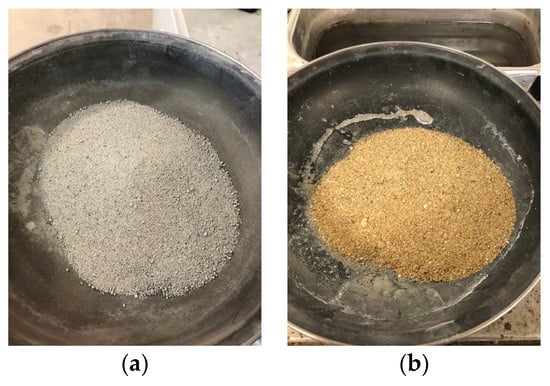
Figure 2.
Used foundry (a) sand and silica sand (b).
The UFS was proportioned by a foundry company in Reinosa, Spain. Table 2 and Table 3 show the absorption of the sands used in this study and the chemical composition of the UFS, respectively. It can be observed that the UFS presents a higher absorption than the SS, which is in concordance with findings in the literature [1]. Moreover, it is observed that the main components of the UFS are SiO2, CaO and Al2O3, as reported by other authors [1,36,37].
Table 2.
Physical properties of the aggregates used.
Table 3.
UFS chemical composition.
2.2. Mix Proportions
Table 4 shows a description of the 32 different mix proportions used in this research work. For all the mixes, the cement content was fixed at 500 g. The design of these dosages is to investigate the effect of UFS on workability, physical and mechanical properties, and mechanical durability.
Table 4.
Mortar mix proportion descriptions.
2.3. Methods
2.3.1. Workability
The workability of all the mortars was tested on the flow table as described in EN-1015-3 standard [38]. The objective of this test was to analyse the influence of the W/C ratio as UFS% increased, based on the workability of the control mortar (0% UFS and 0.50 W/C ratio).
2.3.2. Physical Properties
The evolution of specific gravity, dry density and bulk density were obtained according to EN 12390-7 [39] on the mortar specimens (*). The accessible porosity and the absorption coefficient were obtained according to UNE 83980 [40] on the same specimens (*).
2.3.3. Mechanical Properties
At 28 days, the flexural strength of the 32 mixes was tested according to EN-1015-11 [41] on standardised mortar specimens of 40 mm × 160 mm × 160 mm. After the flexural strength test was performed, the two halves of the mortar were tested for compressive strength according to the same standard [41]. Figure 3 shows the setup of the respective mechanical test.
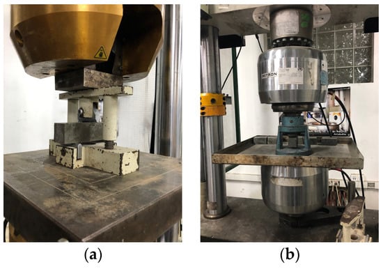
Figure 3.
Set up of the flexural (a) and compression strength test (b).
2.3.4. Wear Resistance
The mortar specimens were previously painted black in order to better appreciate the abrasion marks. The wear resistance test was performed according to EN-1338 [42] (Annex G) on the 3 faces of the standardised mortar specimens (**) at the age of 28 days (Figure 4).
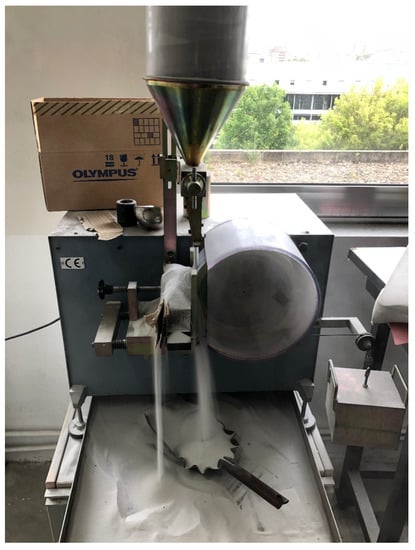
Figure 4.
Set up of the abrasion wear resistance test.
2.3.5. Variable Correlation
In order to perform the statistical analysis, a colour code matrix was made using the Pearson correlation coefficient (r) parameter with the use of Python [43]. If this parameter is close to 1, it implies that both variables are highly correlated in a directly proportional way. If this value is close to −1, it implies that they are strongly correlated in an inversely proportional way. If this value is close to 0, it implies that there is no strong linear correlation between the two variables.
2.3.6. Microstructural Characterisation
A scanning electron microscope (SEM) equipped with X-ray energy dispersive microanalysis capabilities was used to study the microstructure of select samples. As there are several water–cement ratios in each one of the mortar mixtures, an intermediate ratio was taken, in this case, 0.6, taking 5 different samples in total. Prior to analysis under the microscope, the 5 samples were taken and left in the oven for 24 h, then removed and metalised, as shown in Figure 5, to facilitate their observation in the SEM. The samples were sprayed with a thin layer of gold in a pulverisation process in order to increase their conductive properties. It is necessary because mortars are not good conductive materials.
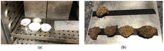
Figure 5.
Sample preparation for SEM analysis: oven drying at 70 °C (a); samples after metallisation (b).
The samples analysed in the SEM were reduced to a size suitable for obtaining micrographic images. In order to assess the compactness of the material, the growth of cement hydration products and the possible cracks generated in the mechanical tests were studied.
3. Results and Discussion
3.1. Workability
Figure 6a shows the effect of both the W/C ratio and the UFS on the slump table result test. The fitting equations for each UFS replacement percentage show that, in general, there is a linear relationship between increasing W/C ratio and slump. If the methodology is replicated in another study, validated results can be guaranteed for each replacement percentage. It also shows that the higher the UFS replacement, the higher the W/C ratio to obtain the same workability Figure 6b shows an example of the visual appearance of two of the tests carried out, namely the 50% UFS case, but for W/C ratios of 0.52 and 0.57, respectively.

Figure 6.
Mortar workability: slump table test results in cm (a) and comparative example for a fixed UFS value (b).
As shown in Figure 6b, the high absorption of the UFS influences the workability of the mortar. It can be observed that with a W/C ratio of 0.52, the slump diameter is 100 mm, i.e., the lower diameter of the cone. For a W/C ratio of 0.57, a higher workability is obtained, resulting in a slump diameter of 150 mm. It is also possible to conclude that to obtain similar workability, increasing the UFS requires an increase in the amount of water. In particular, to obtain workability similar to that obtained in the reference mortar with a W/C ratio of 0.5 in the case of a UFS replacement equal to 50%, the W/C ratio should be 0.57, and 0.7 in the case of a UFS replacement of 100%.
From the results shown in Figure 7a, it is worth noting that there are no data for high UFS values and low W/C ratios. This is because these mixes were too dry, and it was not possible to achieve acceptable workability. The reduction in workability with the increase in UFS was also observed in other studies [1,22,31]. In this regard, Figure 7b shows that for the same W/C (0.5), the slump diameter decreases with higher UFS replacement; from UFS 50 onwards, there is no slump, so the diameter is the same that the flow mould (10 cm). This reduction in workability for high UFS replacement is justified because UFS has a much higher absorption than SS [3,44]. From Figure 7a, it is also possible to see that, in general, a high W/C ratio and low UFS values increase workability. However, the maximum workability values are found with a UFS of 25%. This is because the smaller UFS particle size facilitates particle mobility. Therefore, it is possible to conclude that the presence of UFS has two opposing effects: on the one hand, the particle geometry improves the workability of the mixes, as stated by de Barros et al. [45], and on the other hand, the higher absorption of UFS means that, especially for high UFS replacements, larger quantities of water are required to obtain similar workability.
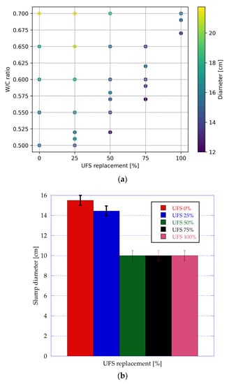
Figure 7.
Mortar workability: slump table test results in cm (a); effect of UFS in mortar workability with W/C = 0.5 (b).
In Figure 8, the effect of modifying the UFS replacement is observed; as mentioned in the previous paragraph, the UFS has a strong influence on the mortar workability. The reduction in the workability is because of the high absorption of the UFS. This prevents the proper workability of mortars with low W/C ratios; in consequence, higher W/C ratios are necessary to obtain the same workability as the control mortar. This loss of workability is more evident as the percentage of replacement increases.
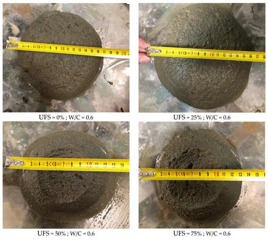
Figure 8.
Mortar workability: slump table test results. Comparative example for a fixed W/C ratio.
3.2. Physical Characterisation of Mortars
Figure 9, Figure 10 and Figure 11 show the evolution of apparent specific gravity, dry density and bulk density as a function of UFS replacement and W/C ratio.
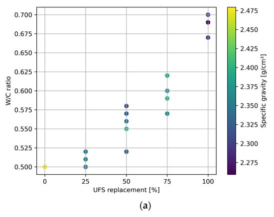

Figure 9.
Specific gravity (g/cm3) of the mortar mixes (a) and decrease in the specific gravity (%) (b).
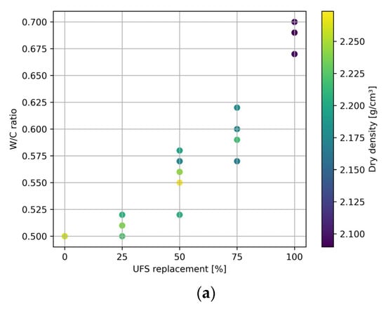

Figure 10.
Dry density (g/cm3) of the mortar mixes (a) and dry density decrease (%) (b).
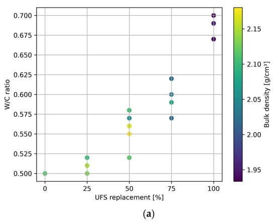
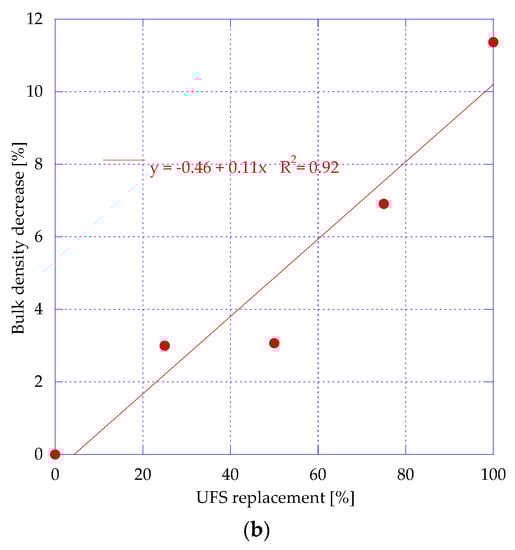
Figure 11.
Bulk density of the mortar mixes (g/cm3) (a) and bulk density decrease (%) (b).
Figure 9a shows that increasing the UFS decreases the specific gravity of the mortars, which is because, as previously stated, to increase the workability, the W/C should be increased. This increase generates air voids within the matrix, generating a loss of density. In general, it can be observed that mortars with UFS of 100% and W/C of 0.7 showed the lowest densities compared to the control mortar. Figure 9b shows the percentual decrease in the specific gravity between the mortar mixes with UFS 25, 50, 75 and 100% compared with the reference mix (UFS 0%). It is observed that there is a minimal difference between the decrease in UFS 25% and UFS 50% mortars, but as the UFS increases up to 100%, it is evident that the decrease in the specific gravity is higher because the higher W/C ratios needed to manufacture the mortars.
Figure 10a shows the influence of increasing UFS and W/C on dry density. As in the previous figure, it can be observed that the mortar with UFS of 100% presents the lowest densities with a W/C of 0.7. On the other hand, mortars with UFS of 25% and W/C up to 0.57 present dry densities similar to those of the control mortar. Figure 10b shows the percentual decrease in the dry density as the UFS increases; this is because the higher W/C ratios form voids within the mortar matrix, creating a more porous and lighter structure.
Figure 11a shows that mortars with UFS of 25% and W/C up to 0.53 achieved similar bulk saturated densities to the control mortar. For mortars with UFS of 50% and W/C between 0.55 and 0.57, a similar behaviour is observed, while for the mortars with UFS of 100%, a decrease in bulk density is observed. Figure 11b shows a similar behaviour as the previous plot; the decrease difference between UFS 25% and UFS 50% is minimal, but as the UFS increases, the percentual decrease in the bulk density is higher because of the higher W/C ratio.
Figure 12 shows the results for the porosity of mortars with different percentages of UFS and W/C ratios. It is observed that, compared to the control mortar, the porosity of mortars with UFS of 25 and 50% is very similar even with higher W/C ratios; this may be due to the fact that FS contains a higher proportion of fines than SS, creating a denser matrix as stated by other authors [46]. On the other hand, mortars with UFS of 75 and 100% present a higher porosity than the control mortar; this is because although the UFS presents more fines, increases in the W/C ratio increase the air void content within the matrix, making it more porous.
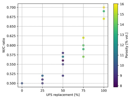
Figure 12.
Accessible porosity of mortars with UFS (% vol.).
Figure 13 presents the absorption results in relation to the UFS and W/C ratio. It is well known that porosity is directly related to absorption, so an explanation similar to the one presented in the previous figure is applied in this case. In general, mortars with UFS replacement up to 50% and W/C ratios up to 0.58 show absorptions similar to those of the control mortar.
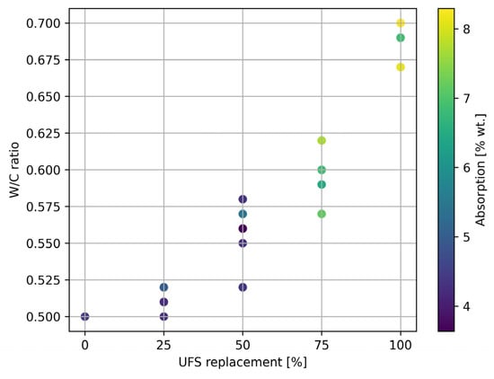
Figure 13.
Absorption coefficient of mortars with UFS (% wt.).
3.3. Mechanical Characterisation of Mortars
Figure 14 shows the flexural strength results as a function of the W/C ratio and the UFS replacement, while Figure 15 shows the values of compressive strength as a function of the same two parameters.
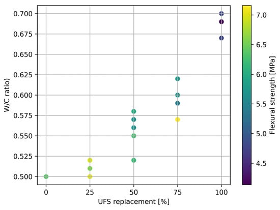
Figure 14.
Flexural strength (MPa) as function of W/C ratio and UFS replacement.
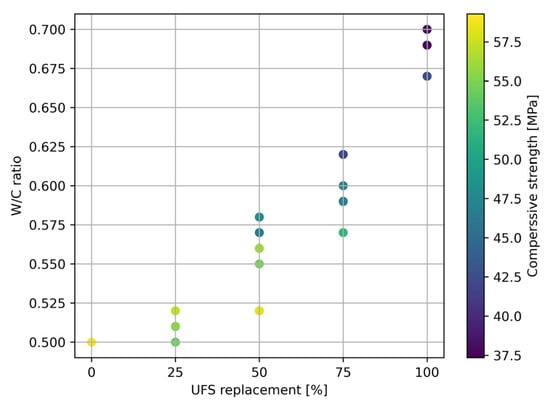
Figure 15.
Compressive Strength (MPa) as function of W/C ratio and UFS replacement.
From the results shown in Figure 14 and Figure 15, it can be concluded that for high W/C ratios and/or high UFS replacements, the mechanical properties of the mortars are reduced. The effect of increasing the W/C ratio on the mechanical properties is clearly documented. From these results, robust conclusions cannot be drawn on the effect of UFS replacement on compressive strength, as there are no case studies with the same W/C ratios and different UFS values. For this reason, these results were completed with the second batch of mixes, which enables the comparison of test specimens (Figure 16) with the same W/C ratio and different UFS replacements. These results are shown in Figure 17a.
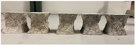
Figure 16.
Mortar specimens with UFS, from 0 to 100%.
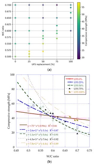
Figure 17.
Compressive strength of mortars (MPa) (a) and W/C ratio influence on compressive strength of UFS mortars (b).
As previously stated, Figure 17a confirms that increasing the W/C ratio generally decreases the mechanical performance of the mortars. An exception occurs for a UFS replacement of 100%, where the lowest compressive strength is observed for a W/C ratio of 0.6, and it increases with the W/C ratio. This is because, in the case of 100% UFS and a W/C ratio of 0.6, the workability of the specimens was very low, the mortar was too dry, and the specimens had defects that were detrimental to their strength. Regarding the effect of the UFS replacement on the compressive strength for constant W/C values, there is no uniform trend for all cases. This is because, as previously stated, there are two phenomena that have opposite effects on the strength of the mortars. In general, given a fixed W/C ratio, an increase in UFS replacement reduces the mechanical properties of the mortars, as also reported by other authors [1,22,31,47]. However, as UFS has a higher absorption than the SS, this water absorption can, in some cases, lead to an increase in the mechanical properties of mortar and concrete, as reported by other authors [30,48], because the finer particles of the UFS fill the pores of the mortar matrix, resulting in a denser material. This is especially seen in cases of very high W/C ratios and UFS replacements. This phenomenon is similar to recycled concrete, where recycled aggregates from concrete also have a higher absorption [49].
Figure 17b shows the influence of the W/C ratio on the compressive strength of mortars with UFS. In general, it is observed that there is a trend in the loss of compressive strength as the UFS replacement increases, as reported in the literature. The fitting equations for each UFS replacement percentage show the relationship between increasing W/C ratio and decreasing compressive strengths. It is observed that a small variation in the W/C ratio has a major influence on compressive strength when higher percentages of UFS are used. Moreover, it is observed that the slope increases with increasing UFS. For low W/C ratios (0.5–0.52), UFS 25% mortars present an initial tendency to increase their compressive strength up to 5%, but at high W/C ratios (0.55 to 0.7), there is a loss of compressive strength of 17, 19, 23 and 49%, respectively. The UFS 50% mortars show similar behaviour, and it is observed that with a W/C ratio of 0.52, the compressive strength is slightly higher than that of UFS 25% (2%); at a W/C ratio of 0.55, this increase is 22%. However, as the W/C increases from 0.6 to 0.7, the compressive strength losses are 32 and 53%, respectively. In the case of UFS 75% mortars, as in the other two cases, there is a tendency to lose compressive strength. It is worth mentioning that there are no W/C ratios of 0.5 and 0.55 in these mortars because the high absorption of UFS makes it difficult to make specimens, so higher W/C ratios were used. By comparing the compressive strength of the UFS 75% with a W/C ratio of 0.57 (51.75 MPa), it was observed that the increase in W/C ratio decreases the compressive strengths by 10, 32 and 64% as the W/C is 0.6, 0.65 and 0.7, respectively. The loss of compressive strength is due to the high W/C ratios necessary to produce mortars with the same workability as the control mortar. These high W/C ratios in mortars with higher UFS replacements create a porous material, resulting in a less dense and less resistant matrix.
3.4. Mechanical Durability
Figure 18 shows the wear results as a function of the UFS replacement amount for samples with the same workability. This parameter evaluates the mechanical durability of the mortars.
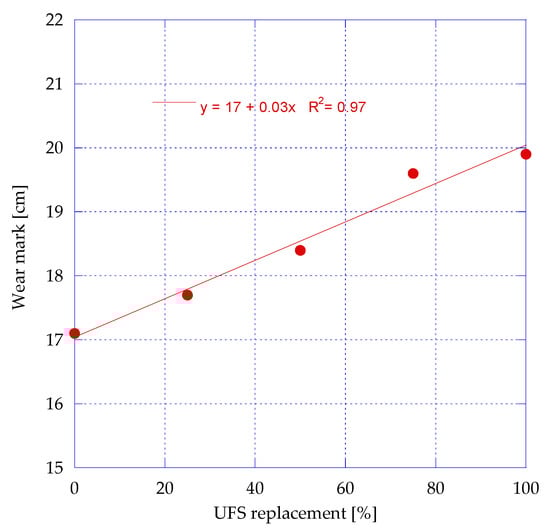
Figure 18.
Wear resistance.
From the results shown in Figure 18, it can be concluded that increasing the FSR increases the wear value obtained in the test. The mechanical durability of mortars decreases with increasing UFS replacement. This is because mortars need a high W/C ratio to achieve the same workability. This results in a more porous material, which could be because it creates a loss of bond between the aggregates and the cement, as mentioned by other authors [50,51,52]. Nevertheless, even with an FSR of 100%, the values obtained remain below the most restrictive value defined in EN-1338 [42], which is 20 mm. Figure 19 shows examples of the specimens’ appearance after the wear resistance tests.
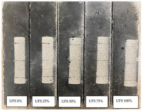
Figure 19.
Examples of the specimen surface after the wear resistance tests.
3.5. Variable Correlation
Figure 20 shows the correlation matrix of the results obtained in this work.
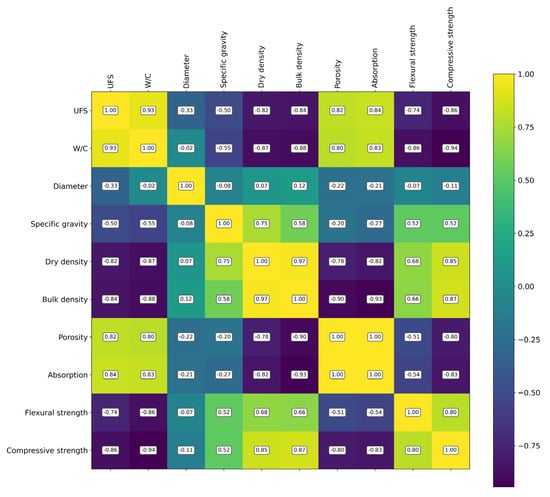
Figure 20.
Correlation matrix of analysed parameters.
The properties of the mortars can be grouped into four families or blocks: (1) workability, which includes “diameter”; (2) densities, which includes specific gravity, dry density and bulk density; (3) compactness, which includes both porosity and absorption; and (4) mechanical properties, which includes flexural strength and compressive strength. Figure 20 shows that there is a high linear correlation between the quantities in each family. There is no clear correlation between workability and any of the other three families of properties. However, the properties in the density family are anti-correlated to the properties in the compactness family and relatively well-correlated to the mechanical properties. Finally, an inverse correlation between the compactness and mechanical properties of blocks is also observed.
Regarding the effect of FSR and W/C on the workability block, we can see that there is no clear trend in relation to either of these two variables. This is because it is a parameter that depends on both variables simultaneously, and each one has an inverse effect. The greater the amount of water, the greater the diameter, but the greater the FSR, the smaller the diameter. For this reason, it can be said that there is one effect that cancels out the other.
Regarding the density block, it can be observed that there is an inverse relationship between the density values and both FSR and W/C. Moreover, it can be stated that this inversely proportional relationship is clearer in the case of dry density and bulk density than in the case of specific gravity.
Regarding the compactness block, it can be observed that there is a directly proportional correlation; the higher the FSR or W/C, the higher the values of voids.
Finally, in the case of mechanical properties, it can be concluded that, as with densities, the higher the values of both FSR and W/C, the lower the values of the mechanical properties.
3.6. Microstructural Characterisation
Figure 21 shows microstructural figures of samples with a W/C ratio of 0.6 and different UFS replacement ratios for 25× magnifications.
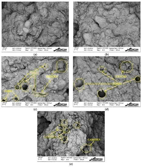
Figure 21.
Microstructural analysis under 25× magnification: pores, cracks and cavities of UFS mortars with 0% (a), 25% (b), 50% (c), 75% (d) and 100% (e) substitution.
Figure 21 shows that mortars with 0% and 25% UFS have a homogeneous paste without any visible pores. This could be because the low UFS replacement allows adequate workability despite the high absorption of the UFS. On the other hand, for 50% and 75% UFS, pores can be observed in the mortar paste. Finally, for 100% UFS, it can be observed that the paste has large cavities, probably because the UFS absorbed most of the water.
Figure 22 shows microstructural figures of samples with a W/C ratio of 0.6 and different FSR ratios for 500× magnifications.
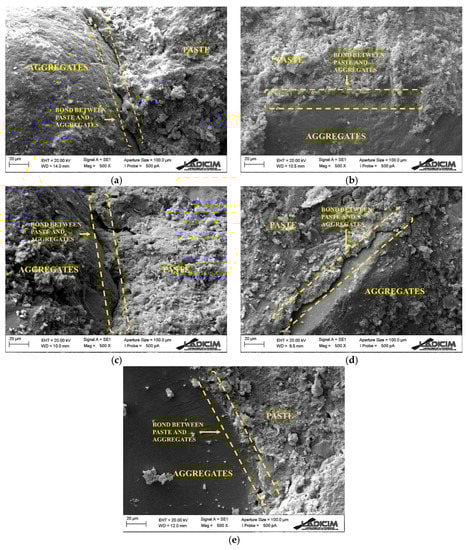
Figure 22.
Microstructural analysis under 500× magnification: bond between paste and aggregates of UFS mortars with 0% (a), 25% (b), 50% (c), 75% (d) and 100% (e) substitution.
Figure 22 shows how the paste and aggregate interact in the mixture. For UFS of 0 and 25%, good bonding between the aggregate and the paste can be observed. It can also be seen that as the UFS replacement increases, the bonding between the paste and the aggregate becomes poorer as the space between the aggregate and the paste increases.
4. Conclusions and Future Work
In this research, 32 mix proportions were manufactured to study the effect of the UFS replacement and the water–cement ratio (W/C) on the workability, physical and mechanical properties, durability, and microstructural characteristics of mortars. After analysing the results, the following conclusions can be drawn:
- Increasing the UFS replacement reduces the workability of the mixes, making it impractical to manufacture mortars with high UFS replacement and low W/C ratios.
- Increasing the UFS replacement decreases the compactness of the mortars, so it is necessary to increase the W/C ratio, reducing the specific gravity, dry density and bulk density and increasing the porosity and absorption.
- Low quantities of UFS replacement can lead to a slight improvement in mechanical properties, while high UFS replacement requires high W/C ratios and, consequently, it is not possible to achieve high values of mechanical properties.
- For the same workability, increasing the UFS replacement increases the wear value obtained. Even with a UFS replacement of 100%, the values obtained remain below the most restrictive value, which is 20 mm.
- From microstructural characterisation, it can be concluded that in mortars with low UFS replacement, the paste and the aggregate are uniformly distributed without the presence of pores and with good adhesion between the paste and the aggregate. When the UFS replacement increases, pores begin to appear in the mortar.
- From a practical point of view, the authors recommend using up to 25% replacement of UFS because, with a minimum amount of extra water, a workability equal to that of a conventional mortar is obtained; it has slightly higher mechanical strengths, and the mechanical durability is very similar to that of a control mortar.
- Future studies should be carried out in the field of mortars with UFS to increase the replacement percentage without increasing the W/C ratio, maintaining the same workability.
Author Contributions
Conceptualisation, G.G.D.A., P.T. and C.T.; methodology, G.G.D.A., J.A.S.-A., P.T., A.C., R.C., L.R.P. and C.T.; validation, G.G.D.A., J.A.S.-A., P.T., A.C. and C.T.; formal analysis, G.G.D.A., J.A.S.-A., P.T., L.R.P., A.C. and C.T.; investigation, G.G.D.A., J.A.S.-A., P.T. and A.C.; resources, R.C. and C.T.; data curation, G.G.D.A., J.A.S.-A. and P.T.; writing—original draft preparation, G.G.D.A., J.A.S.-A. and P.T.; writing—review and editing, G.G.D.A., J.A.S.-A. and C.T.; visualisation, R.C., L.R.P., A.C. and C.T.; supervision, R.C. and C.T.; project administration, R.C. and C.T.; funding acquisition, R.C. and C.T. All authors have read and agreed to the published version of the manuscript.
Funding
This research was partially funded by SODERCAN, Cantabria, Spain.
Institutional Review Board Statement
Not applicable.
Informed Consent Statement
Not applicable.
Data Availability Statement
Not applicable.
Acknowledgments
The authors of this research would like to thank Reinosa Forgings & Castings for the foundry sand as well as the Mexico board, Consejo Nacional de Ciencia y Tecnología (CONACYT), for support during this project.
Conflicts of Interest
The authors declare no conflict of interest.
References
- Garcia Del Angel, G.; Thomas, C. The use of foundry sand for recycled aggregate concrete. In The Structural Integrity of Recycled Aggregate Concrete Produced with Fillers and Pozzolans; Elsevier: Amsterdam, The Netherlands, 2022; pp. 3–24. [Google Scholar] [CrossRef]
- Foundry Industry Recycling Starts Today (FIRST); United States Environmental Protection Agency. Foundry Sand Facts for Civil Engineers; Federal Highway Administration: Washington, DC, USA, 2004. [Google Scholar]
- Monosi, S.; Sani, D.; Tittarelli, F. Used Foundry Sand in Cement Mortars and Concrete Production. Open Waste Manag. J. 2010, 3, 18–25. [Google Scholar] [CrossRef]
- Jesus, C.; Arruda Junior, E.; Braga, N.S.; Silva Junior, J.; Barata, M.S. Coloured Concrete Produced from Low-Carbon Cements: Mechanical Properties, Chromatic Stability and Sustainability. J. Build. Eng. 2023, 67, 106018. [Google Scholar] [CrossRef]
- Cui, K.; Chang, J. Hydration, reinforcing mechanism, and macro performance of multi-layer graphene-modified cement composites. J. Build. Eng. 2022, 57, 104880. [Google Scholar] [CrossRef]
- Aksoylu, C.; Özkılıç, Y.O.; Hadzima-Nyarko, M.; Işık, E.; Arslan, M.H. Investigation on Improvement in Shear Performance of Reinforced-Concrete Beams Produced with Recycled Steel Wires from Waste Tires. Sustainability 2022, 14, 13360. [Google Scholar] [CrossRef]
- Zeybek, Ö.; Özkılıç, Y.O.; Çelik, A.İ.; Deifalla, A.F.; Ahmad, M.; Sabri Sabri, M.M. Performance evaluation of fiber-reinforced concrete produced with steel fibers extracted from waste tire. Front. Mater. 2022, 9, 1057128. [Google Scholar] [CrossRef]
- Basaran, B.; Kalkan, I.; Aksoylu, C.; Özkılıç, Y.O.; Sabri, M.M.S. Effects of Waste Powder, Fine and Coarse Marble Aggregates on Concrete Compressive Strength. Sustainability 2022, 14, 14388. [Google Scholar] [CrossRef]
- Karalar, M.; Özkılıç, Y.O.; Aksoylu, C.; Sabri Sabri, M.M.; Beskopylny, A.N.; Stel’makh, S.A.; Shcherban’, E.M. Flexural behavior of reinforced concrete beams using waste marble powder towards application of sustainable concrete. Front. Mater. 2022, 9, 701. [Google Scholar] [CrossRef]
- Çelik, A.İ.; Özkılıç, Y.O.; Zeybek, Ö.; Özdöner, N.; Tayeh, B.A. Performance Assessment of Fiber-Reinforced Concrete Produced with Waste Lathe Fibers. Sustainability 2022, 14, 11817. [Google Scholar] [CrossRef]
- Karalar, M.; Özkılıç, Y.O.; Deifalla, A.F.; Aksoylu, C.; Arslan, M.H.; Ahmad, M.; Sabri, M.M.S. Improvement in Bending Performance of Reinforced Concrete Beams Produced with Waste Lathe Scraps. Sustainability 2022, 14, 12660. [Google Scholar] [CrossRef]
- Çelik, A.İ.; Özkılıç, Y.O.; Zeybek, Ö.; Karalar, M.; Qaidi, S.; Ahmad, J.; Burduhos-Nergis, D.D.; Bejinariu, C. Mechanical Behavior of Crushed Waste Glass as Replacement of Aggregates. Materials 2022, 15, 8093. [Google Scholar] [CrossRef]
- Qaidi, S.; Najm, H.M.; Abed, S.M.; Özkılıç, Y.O.; Al Dughaishi, H.; Alosta, M.; Sabri, M.M.S.; Alkhatib, F.; Milad, A. Concrete Containing Waste Glass as an Environmentally Friendly Aggregate: A Review on Fresh and Mechanical Characteristics. Materials 2022, 15, 6222. [Google Scholar] [CrossRef]
- Karalar, M.; Bilir, T.; Çavuşlu, M.; Özkiliç, Y.O.; Sabri, M.M. Use of recycled coal bottom ash in reinforced concrete beams as replacement for aggregate. Front. Mater. 2022, 9, 1064604. [Google Scholar] [CrossRef]
- Qaidi, S.; Al-Kamaki, Y.; Hakeem, I.; Dulaimi, A.F.; Özkılıç, Y.; Sabri, M.; Sergeev, V. Investigation of the physical-mechanical properties and durability of high-strength concrete with recycled PET as a partial replacement for fine aggregates. Front. Mater. 2023, 10, 3085. [Google Scholar] [CrossRef]
- Tittarelli, F. 4-Waste foundry sand. In Waste and Supplementary Cementitious Materials in Concrete; Woodhead Publishing Series in Civil and Structural Engineering; Siddique, R., Cachim, P., Eds.; Woodhead Publishing: Sawston, UK, 2018; pp. 121–147. ISBN 978-0-08-102156-9. [Google Scholar]
- Mavroulidou, M.; Lawrence, D. Can waste foundry sand fully replace structural concrete sand? J. Mater. Cycles Waste Manag. 2019, 21, 594–605. [Google Scholar] [CrossRef]
- Bhardwaj, B.; Kumar, P. Waste foundry sand in concrete: A review. Constr. Build. Mater. 2017, 156, 661–674. [Google Scholar] [CrossRef]
- Siddique, R.; Noumowe, A. Utilization of spent foundry sand in controlled low-strength materials and concrete. Resour. Conserv. Recycl. 2008, 53, 27–35. [Google Scholar] [CrossRef]
- Del Angel, G.G.; Aghajanian, A.; Tamayo, P.; Rico, J.; Thomas, C. Siderurgical Aggregate Cement-Treated Bases and Concrete Using Foundry Sand. Appl. Sci. 2021, 11, 435. [Google Scholar] [CrossRef]
- Etxeberria, M.; Vázquez, E.E.; Mari, A.; Barra, M. Influence of amount of recycled coarse aggregates and production process on properties of recycled aggregate concrete. Cem. Concr. Res. 2007, 37, 735–742. [Google Scholar] [CrossRef]
- Monosi, S.; Tittarelli, F.; Giosuè, C.; Ruello, M.L. Effect of two different sources and washing treatment on the properties of UFS by-products for mortar and concrete production. Constr. Build. Mater. 2013, 44, 260–266. [Google Scholar] [CrossRef]
- Siddique, R.; Sandhu, R.K. Properties of Self-Compacting Concrete Incorporating Waste Foundry Sand. Leonardo J. Sci. 2013, 23, 105–124. [Google Scholar]
- Sandhu, R.K.; Siddique, R. Strength properties and microstructural analysis of self-compacting concrete incorporating waste foundry sand. Constr. Build. Mater. 2019, 225, 371–383. [Google Scholar] [CrossRef]
- Cunha, S.; Tavares, A.; Aguiar, J.B.; Castro, F. Cement mortars with ceramic molds shells and paraffin waxes wastes: Physical and mechanical behavior. Constr. Build. Mater. 2022, 342, 127949. [Google Scholar] [CrossRef]
- Ramon Roque da Silva, L.; Cirino Gaspar, F.; Cesar Gonçalves, P.; Claret dos Santos, V.; de Lourdes Noronha Motta Melo, M.; Ferreira Gomes, G. An experimental dynamic study of cement mortar with polyurethane residues and foundry sand. Eng. Struct. 2023, 274, 115107. [Google Scholar] [CrossRef]
- de Paiva, F.F.G.; dos Santos, L.F.; Tamashiro, J.R.; Pereira Silva, L.H.; Teixeira, S.R.; Galvín, A.P.; López-Uceda, A.; Kinoshita, A. Effect of phenolic resin content in waste foundry sand on mechanical properties of cement mortars and leaching of phenols behaviour. Sustain. Chem. Pharm. 2023, 31, 100955. [Google Scholar] [CrossRef]
- Sabour, M.R.; Derhamjani, G.; Akbari, M. Mechanical, durability properties, and environmental assessment of geopolymer mortars containing waste foundry sand. Environ. Sci. Pollut. Res. 2022, 29, 24322–24333. [Google Scholar] [CrossRef]
- Vázquez-Rodriguez, F.J.; Valadez-Ramos, J.; Puente-Ornelas, R.; Contreras, J.E.; Arato, A.; Rodríguez, E.A. Nonferrous waste foundry sand and milling fly ash as alternative low mechanical strength materials for construction industry: Effect on mortars at early ages. Rev. Rom. Mater. Rom. J. Mater. 2018, 48, 338–345. [Google Scholar]
- Çevik, S.; Mutuk, T.; Oktay, B.M.; Demirbaş, A.K. Mechanical and microstructural characterization of cement mortars prepared by waste foundry sand (WFS). J. Aust. Ceram. Soc. 2017, 53, 829–837. [Google Scholar] [CrossRef]
- Matos, P.R.D.; Marcon, M.F.; Schankoski, R.A.; Prudêncio, L.R., Jr. Novel applications of waste foundry sand in conventional and dry-mix concretes. J. Environ. Manag. 2019, 244, 294–303. [Google Scholar] [CrossRef]
- Cui, K.; Liang, K.; Chang, J.; Lau, D. Investigation of the macro performance, mechanism, and durability of multiscale steel fiber reinforced low-carbon ecological UHPC. Constr. Build. Mater. 2022, 327, 126921. [Google Scholar] [CrossRef]
- EN 197-1; Cement Part 1: Composition, Specifications and Conformity Criteria for Common Cements. European Committee For Standardisation: London, UK, 2011.
- UNE 80103:2013; Test Methods of Cements. Physical Analysis. Actual Density Determination. UNE: Madrid, Spain, 2013.
- EN 196-6; Methods of Testing Cement-Part 6: Determination of Fineness. European Committee For Standardisation: London, UK, 2010.
- Paul, P.; Belhaj, E.; Diliberto, C.; Apedo, K.L.; Feugeas, F. Comprehensive characterization of spent chemical foundry sand for use in concrete. Sustainability 2021, 13, 12881. [Google Scholar] [CrossRef]
- Parashar, A.; Aggarwal, P.; Saini, B.; Aggarwal, Y.; Bishnoi, S. Study on performance enhancement of self-compacting concrete incorporating waste foundry sand. Constr. Build. Mater. 2020, 251, 118875. [Google Scholar] [CrossRef]
- EN 1015-3; Methods of Test for Mortar for Masonry. Part 3: Determination of Consistence of Fresh Mortar (by Flow Table). Turkish Standard Institute: Ankara, Turkey, 2000.
- EN 12390-7; Testing Hardened Concrete-Part 7: Density of Hardened Concrete. European Committee For Standardisation: London, UK, 2020.
- EN 83980; Concrete Durability. Test Methods. Determination of the Water Absorption, Density and Accessible Porosity for Water in Concrete. European Committee For Standardisation: London, UK, 2014.
- EN 1015-11; Methods of Test for Mortar for Masonry-part 11: Determination of Flexural and Compressive Strength of Hardened Mortar. European Committee For Standardisation: London, UK, 2020.
- EN 1338; Concrete Paving Blocks-Requirements and Test Methods. European Committee For Standardisation: London, UK, 2004.
- Pandas Pearson Correlation. Available online: https://pandas.pydata.org/docs/reference/api/pandas.DataFrame.corr.html (accessed on 9 February 2023).
- Srivastava, A.; Singh, S.K. Utilization of alternative sand for preparation of sustainable mortar: A review. J. Clean. Prod. 2020, 253, 119706. [Google Scholar] [CrossRef]
- de Barros Martins, M.; Barros, R.M.; Silva, G.; Santos, I.F.S.D. Study on waste foundry exhaust sand, WFES, as a partial substitute of fine aggregates in conventional concrete. Sustain. Cities Soc. 2019, 45, 187–196. [Google Scholar] [CrossRef]
- Siddique, R.; Schutter, G.D.; Noumowe, A. Effect of used-foundry sand on the mechanical properties of concrete. Constr. Build. Mater. 2009, 23, 976–980. [Google Scholar] [CrossRef]
- Khanduri, A. Properties of Mortar Incorporating Waste Foundry Sand; Thapar University: Patiala, India, 2010. [Google Scholar]
- Mushtaq, S.M.; Siddique, R.; Goyal, S.; Kaur, K. Experimental studies and drying shrinkage prediction model for concrete containing waste foundry sand. Clean. Eng. Technol. 2021, 2, 100071. [Google Scholar] [CrossRef]
- Thomas, C.; Setién, J.; Polanco, J.A.A.J.; Alaejos, P.; De Juan, M.S. Durability of recycled aggregate concrete. Constr. Build. Mater. 2013, 40, 1054–1065. [Google Scholar] [CrossRef]
- Sainz-Aja, J.; Carrascal, I.; Polanco, J.; Thomas, C.; Sosa, I.; Casado, J.; Diego, S. Self-compacting recycled aggregate concrete using out-of-service railway superstructure wastes. J. Clean. Prod. 2019, 230, 945–955. [Google Scholar] [CrossRef]
- Laplante, P.; Aïtcin, P.C.; Vézina, D. Abrasion resistance of concrete. J. Mater. Civ. Eng. 1991, 3, 19–28. [Google Scholar] [CrossRef]
- Warudkar, A.; Elavenil, S.; Arunkumar, A. Assessment of abrasion resistance of concrete pavement for durability. Int. J. Civ. Eng. Technol. 2018, 9, 1176–1181. [Google Scholar]


Disclaimer/Publisher’s Note: The statements, opinions and data contained in all publications are solely those of the individual author(s) and contributor(s) and not of MDPI and/or the editor(s). MDPI and/or the editor(s) disclaim responsibility for any injury to people or property resulting from any ideas, methods, instructions or products referred to in the content. |
© 2023 by the authors. Licensee MDPI, Basel, Switzerland. This article is an open access article distributed under the terms and conditions of the Creative Commons Attribution (CC BY) license (https://creativecommons.org/licenses/by/4.0/).