Article

Analytical and Numerical Study of the Axial Stiffness of Fiber-Reinforced Elastomeric Isolators (FREIs) under Combined Axial and Shear Loads

1
Department of Structures for Engineering & Architecture, University of Naples Federico II, Napoli, Via Claudio 21, 80125 Naples, Italy
2
Department of Civil Engineering & Construction Engineering Management, California State University, Long Beach, CA 90840, USA
*
Author to whom correspondence should be addressed.
Appl. Sci. 2023, 13(6), 3515; https://doi.org/10.3390/app13063515
Submission received: 4 February 2023 / Revised: 3 March 2023 / Accepted: 7 March 2023 / Published: 9 March 2023
(This article belongs to the Special Issue Seismic Resistant Analysis and Design for Civil Structures)

Abstract

:

Featured Application

This paper provides an analytical formulation to account for the vertical stiffness reduction of fiber-reinforced elastomeric isolators under combined axial and shear loads. The analytical method can be used in design practice to estimate the vertical stiffness of these seismic devices.

Abstract

Fiber-reinforced elastomeric isolators (FREIs) are rubber-based seismic devices introduced as a low-cost alternative to steel-reinforced elastomeric isolators (SREIs). They are generally used in unbonded applications, i.e., friction is used to transfer the lateral loads from the upper to the lower structure. Under combined axial and shear loads, the lateral edges of the unbonded bearings detach from the top and bottom supports resulting in a rollover deformation. Due to increasing horizontal displacement, the overlap area of the bearing decreases; thus, the vertical properties of the device are a function of the imposed lateral deformation. This paper introduces a closed-form solution to derive the vertical stiffness of the bearings as a function of the horizontal displacement. The variations of the vertical stiffness and of the effective compressive modulus of square-shaped FREIs are given in this work. The analytical results are then validated through a comparison with the outputs of a parametric finite element analysis of FREIs, including different mechanical and geometric parameters.

1. Introduction

Fiber-reinforced elastomeric isolators (FREIs) are made by bonding together layers of elastomer and fiber fabrics [1]. These devices were first used as bridge bearings [2], and then proposed as low-cost seismic devices as alternatives to the more common steel-reinforced elastomeric isolators (SREIs) [3,4]. Several studies demonstrated the advantages of using fiber reinforcements in lieu of steel sheets as the fiber fabrics are lighter than steel [5] and allow for an affordable and rapid manufacturing process (i.e., cold vulcanization) [6].
Although FREIs could be used both in bonded (bonded fiber-reinforced elastomeric isolators, B-FREIs) and unbonded (unbonded fiber-reinforced elastomeric isolators, U-FREIs) applications [7], they are generally adopted in an unbonded configuration. When unbonded, fiber-reinforced bearings under shear loads experience a rollover deformation as the top and bottom surfaces of the devices detach from the supports [8]. The rollover continues until the initial vertical surfaces of the FREI gradually become horizontal and touch the supports, resulting in the full rollover condition [9]. Complex hysteretic behavior of FREIs under lateral loading has been recently addressed by different authors [10,11,12].
The rollover deformation reduces the horizontal stiffness of the device, increasing the efficiency of the isolation system [13]. However, the horizontal stiffness needs to be positive throughout the horizontal deformation in order for the bearing to be stable (stable unbonded fiber-reinforced elastomeric isolators, SU-FREIs); unstable bearings (unstable unbonded fiber-reinforced elastomeric isolators, UU-FREIs) show softening at large lateral deformation prior to full rollover [14,15]. The stability of the U-FREIs depends mostly on the secondary shape factor S 2 , defined as the ratio between the base side in the direction of the horizontal displacement and the total rubber height [16]. Secondary shape factors greater than 2.5 were seen to ensure a stable response to U-FREIs under combined axial and both uni- and bi-directional shear loads [17,18,19,20].
Full-scale FREIs have been recently tested under combined vertical and horizontal uni- and bi-directional motion with different levels of axial pressure [21,22]. Recent studies also demonstrated FREIs being a valuable option for reduction of seismic risk in unreinforced masonry buildings [23,24,25]. In order to further reduce both the environmental impact and the cost of FREIs, reclaimed rubber compounds are under development to replace virgin compounds [26,27].
During the horizontal deformation, the overlap area between upper and lower surfaces reduces, both in bonded and unbonded configurations [28,29]. Thus, the vertical response of the bearing depends on the horizontal displacement as recently addressed by shaking table tests, hybrid simulations and finite element analyses [30,31,32]. Analytical solutions for the vertical stiffness or the effective compressive modulus were proposed for bearings under pure compression [33,34,35,36,37,38,39]. In this condition, the vertical response of the bearings is greatly affected by the primary shape factor S 1 , defined as the ratio of the loaded area to the lateral free-to-bulge area of the single elastomeric layer. To the best of the authors’ knowledge, analytical studies that consider the variation of the axial stiffness as a function of the imposed lateral deformation were developed solely for bearings with rigid reinforcements [40].
This paper studies the vertical stiffness of strip-shaped U-FREIs under combined axial and shear loads. A closed-form analytical solution for the vertical stiffness as a function of the horizontal displacement is proposed. The influence of the main geometric and mechanical parameters of the bearings, such as the primary and secondary shape factors, as well as the shear modulus of the rubber, are studied. Finally, a parametric finite element analysis is used to validate the proposed analytical solution. A set of finite element models (FEMs) of strip-shaped U-FREIs with different geometries and rubber compound were run to compare the analytical and numerical results.

2. Review of the Analytical Solutions for the Vertical Response of FREIs

2.1. Vertical Stiffness and Effective Compressive Modulus

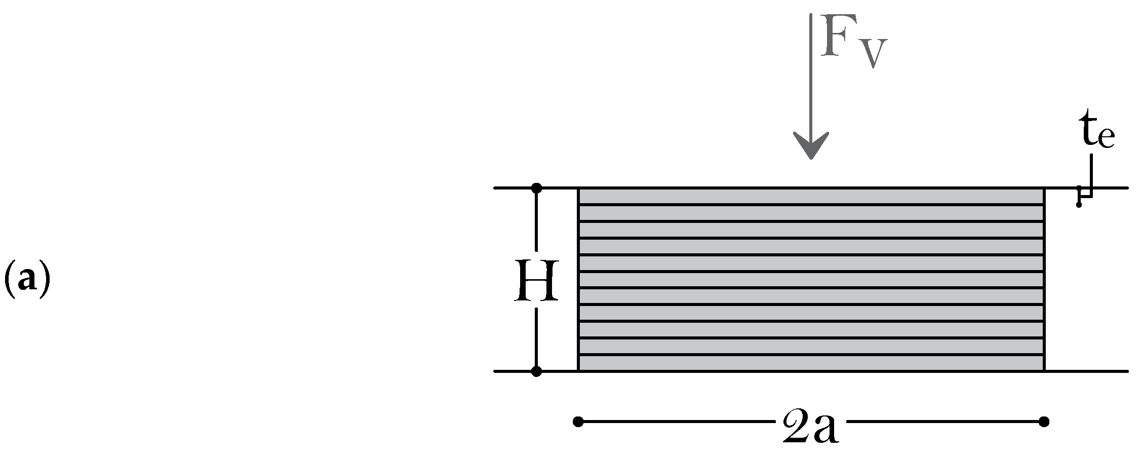
For a strip-shaped FREI with base side 2 a , total height H , thickness of the fiber reinforcement t f and of the elastomeric layer t e , the vertical stiffness under a compressive load F v (Figure 1a) and zero horizontal displacement δ H is given as [41]:
K v δ H = 0 = E c δ H = 0 A c t r
where E c δ H = 0 is the effective compressive modulus under pure compression, A c = 2 a is the contact area between the bearing and the supports, and t r = n t e is the total rubber height ( n is the total number of elastomeric layers). The effective compressive modulus under pure compression is defined as [3]:
E c δ H = 0 = σ v t r δ v
where δ v is the vertical displacement at the top of the bearing, and σ v is the vertical pressure. Different analytical formulations were proposed for E c δ H = 0 of strip-shaped bearings with flexible reinforcements. Two main approaches are herein recalled, namely the Pressure Solution (PS) [28] and the Pressure Approach (PA) [34], considering the elastomer as incompressible and compressible, respectively. With the PS, the modulus can be obtained as:
E c δ H = 0 P S = G S 1 2 12 α a 2 1 tanh α a α a
where G e is the shear modulus of the elastomer, and α = 12 G e 1 ν f 2 / E f t f t e . The primary shape factor of a strip-shaped FREI can be obtained from S 1 = a / t e . With the PA, the effective compressive modulus under pure compression is obtained from:
E c δ H = 0 P A = 2 G e + 2 G e λ λ + 2 G e + λ 2 λ + 2 G e α 0 2 β 0 2 1 tanh β 0 a β 0 a
where λ = K 2 G e / 3 is the second Lamè constant, α 0 = 6 t e G e 3 K + 4 G e ( K is the bulk modulus of the rubber), and β 0 = α 0 2 + α 2 .

2.2. Axial Deformation under Vertical and Lateral Loads
A closed-form analytical solution was proposed for the overall vertical deformation of strip-shaped elastomeric bearings under axial and shear loads [40,42]. The total vertical displacement δ v t is seen as the sum of two quantities: the first one due to pure compression δ v c , while the second one is the effect of the shear deformation δ v s (Figure 1b):
δ v t = δ v c + δ v s = F v K v δ H = 0 + π G e A c 4 F v , c r π f v sin π f v 1 cos π f v δ H 2 H
where F v , c r is the buckling load of the bearing, and f v = F v / F v , c r is the dimensionless ratio of the vertical applied load to the buckling load. Formula (5) was initially derived for bonded elastomeric bearings with rigid reinforcement, but recent studies demonstrated how it can be used to predict the total vertical deformation of unbonded strip-shaped bearings with flexible reinforcement with good accuracy [43].
Different analytical formulations were proposed for the buckling load F v , c r . In Equation (5), the following equation for bearings with rigid reinforcements was first used [44]:
F v , c r , 1 r i g . = 4 π G e a 3 15 t r t e
A solution for the buckling load of bearings with flexible reinforcements was also proposed. F v , c r can be obtained solving the following non-linear equation [45]:
C 1 F v , c r f l e x . G e A c 3 + C 2 F v , c r f l e x . G e A c 2 + C 2 F v , c r f l e x . G e A c C 3 = 0
where C 1 C 4 are constants depending on the geometric and mechanical properties of the bearing as follows:
  • C 1 = E I e f f E J e f f f c A c f B A c 2
  • C 2 = E I e f f E J e f f C A c f c A c 2 f B B A c + π 2 ρ 1 + E I e f f E J e f f f B A c 2
  • C 3 = E I e f f E J e f f C A c B A c 2 + π 2 ρ 1 + E I e f f E J e f f 2 f B B A c 2 f C A c 2
  • C 4 = π 2 ρ E I e f f E J e f f C A c B A c 2 + π 4 ρ 2
  • E I e f f a 3 G e S 1 2 8 15 1 2 21 α a 2
  • E J e f f a G e S 1 2 32 3675 1 2 77 α a 2 + 1 2 λ S 1 3 a / t f 3
  • B 8 7 1 1 210 α a 2
  • C 1 a 552 245 1 1 210 α a 2 + 2 S 1 λ a / t f 3
  • f B 12 35 1 + 16 315 α a 2
  • f C 216 245 a 1 + 26 945 α a 2
  • ρ 4 15 S 1 2 a H 2 1 2 21 α a 2
When the reinforcement tends to be rigid, the solution of Equation (7) tends to [28]:
F v , c r , 2 r i g . = G e A c 1 + 1 + 4 π 2 ρ 2
Figure 1. (a) Definition of the geometric parameters for a strip-shaped U-FREI under a compressive load; (b) vertical displacement due to horizontal displacement of a strip-shaped U-FREI (adapted from [43]).
Applsci 13 03515 g001aApplsci 13 03515 g001b

3. Vertical Stiffness and Effective Compressive Modulus under Axial and Shear Loads: Analytical Solution

3.1. Problem Setting

The vertical stiffness of U-FREIs under combined axial and shear loads can be written as:
K v δ H = F v δ v t = F v δ v c + δ v s
where the notation on the total vertical displacement introduced in Section 2.2 was used. Multiplying and dividing Equation (9) by the non-zero term δ v c , the vertical stiffness as a function of the horizontal displacement becomes.
K v δ H = F v δ v c δ v c δ v c + δ v s = K v δ H = 0 ψ δ H
Equation (10) shows how the vertical stiffness of a U-FREI under combined axial and shear loads can be obtained starting from the vertical stiffness under pure compression using the function ψ δ H , which is defined as the ratio of the vertical displacement under pure compression to the total vertical displacement. Here, ψ δ H modifies the vertical stiffness of the bearing to account for the reduction due to the horizontal deformation and is herein referred as the ψ  function.
ψ δ H is a decreasing function with the horizontal displacement, ranging from a maximum value of 1 to a minimum value of 0 as:
lim δ H 0 ψ δ H = 1 lim δ H δ H , b ψ δ H = 0
where δ H , b is the horizontal displacement where buckling occurs. Accordingly, the vertical stiffness under combined axial and shear loads ranges from a maximum value equal to the vertical stiffness under pure compression to a minimum of 0. Using Equation (1) and recalling the definition of the secondary shape factor of a strip-shaped bearing, the vertical stiffness K v δ H can be also written as:
K v δ H = E c δ H = 0 A c t r ψ δ H = E c δ H = 0 S 2 ψ δ H
A similar approach can be used for the effective compressive modulus of FREIs under combined axial and shear loads. The definitions of E c δ H = 0 (Equation (2)) and of the secondary shape factors lead to:
E c δ H = σ v t r δ v t = K v δ H t r A c = K v δ H S 2 = K v δ H = 0 ψ δ H S 2
This equation shows how the effective compressive modulus as a function of the horizontal displacement can be obtained from the effective compressive modulus under pure compression using the ψ  function.

3.2. Analytical Formulation of the ψ Function

The analytical equation of the ψ  function can be obtained using Equations (5) and (10):
ψ δ H = δ v c δ v c + δ v s = 1 1 + π G e E c δ H = 0 A c 2 4 F v F v , c r t r π f v sin π f v 1 cos π f v δ H 2 H
Considering that S 2 = A c / t r and setting K H , e q = G e A c / H (the horizontal stiffness of an equivalent beam), Equation (14) becomes
ψ δ H = 1 1 + π E c δ H = 0 4 F v F v , c r π f v sin π f v 1 cos π f v δ H 2 S 2 K H , e q
As the ψ function quantifies the reduction of the vertical stiffness and the effective compressive modulus with the horizontal deformation, a larger reduction ψ δ H results in lower values of the vertical response parameters of the bearings. It is also worth adding that the ratio of the vertical stiffness to the horizontal stiffness of an elastomeric bearing needs to be large enough to support the weight of the structure and to avoid rocking motion [8]. Using the ψ function, this ratio can be obtained as
K V δ H K H δ H = ψ δ H K V δ H = 0 K H δ H
where K H δ H is the horizontal secant stiffness value at a generic horizontal displacement. Equation (16) shows how the ratio of stiffness at a generic horizontal displacement δ H can be obtained through the ψ function starting from the ratio between the vertical stiffness under pure compression and the secant horizontal stiffness at δ H . Using the definition of vertical stiffness under pure compression given in Equation (1), Equation (16) becomes:
K V δ H K H δ H = ψ δ H S 2 E c δ H = 0 K H δ H
This ratio can be calculated using Equation (15) for the ψ function, Equations (3) or (4) for the effective compressive modulus and one of the different analytical solutions proposed for the horizontal stiffness of U-FREIs [46,47,48,49,50,51,52].

3.3. Variability of the ψ Function

This section shows the trends of the ψ function with the main geometric and mechanical parameters of the bearing. Equation (15) is applied to strip-shaped FREIs using the following approach. For the effective compressive modulus E c δ H , either Equation (3) or (4) are used, while Equations (6)–(8) are used to determine the buckling load F v , c r . The solutions for E c allow us to estimate the differences between the assumption of compressible and incompressible elastomeric layers, while using the different equations for F v , c r return results on the influence of rigid or flexible reinforcements.
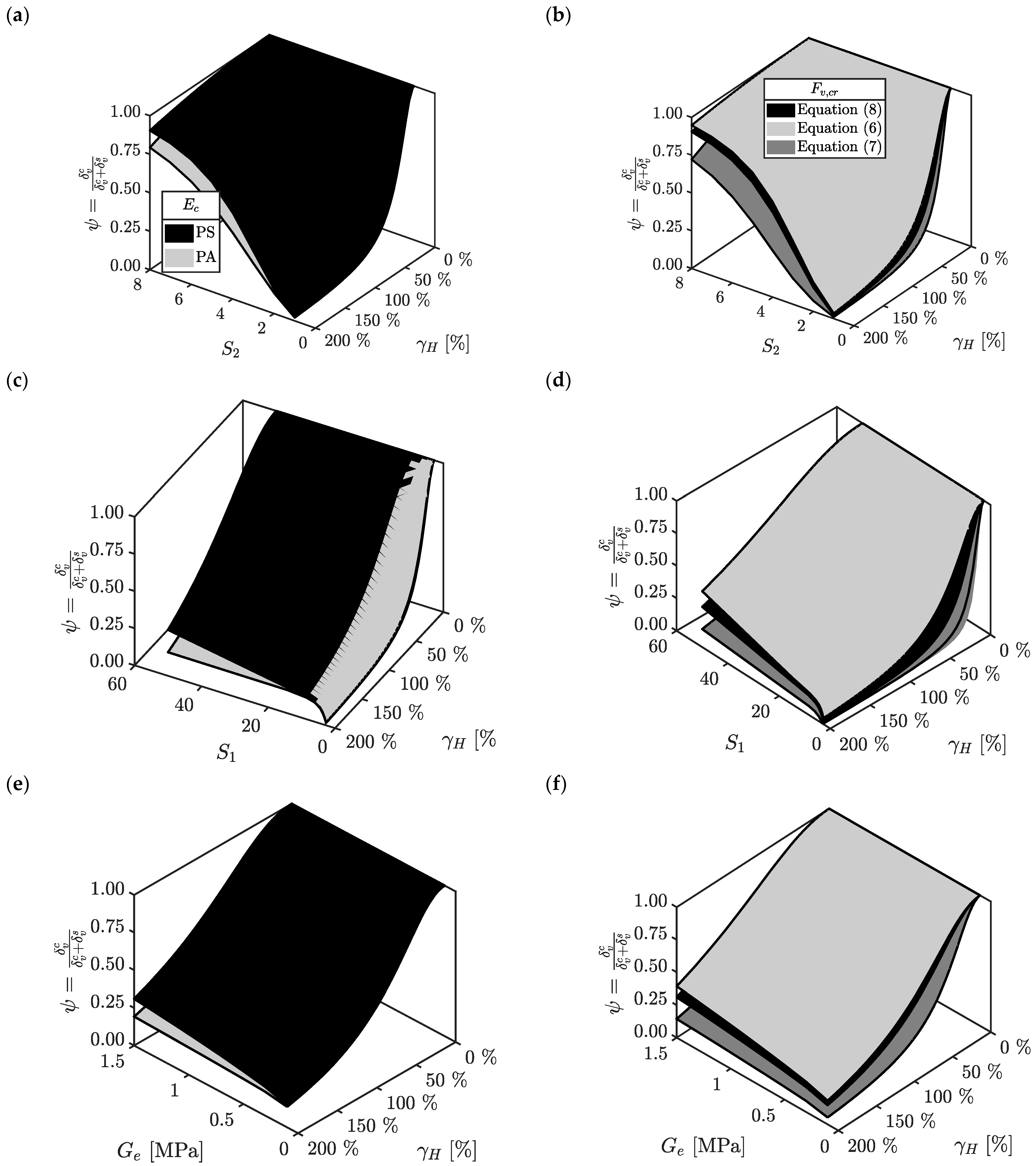
Figure 2 shows the trends of the ψ  function with the shear strain (i.e., γ H = δ H / t r ) and with the:
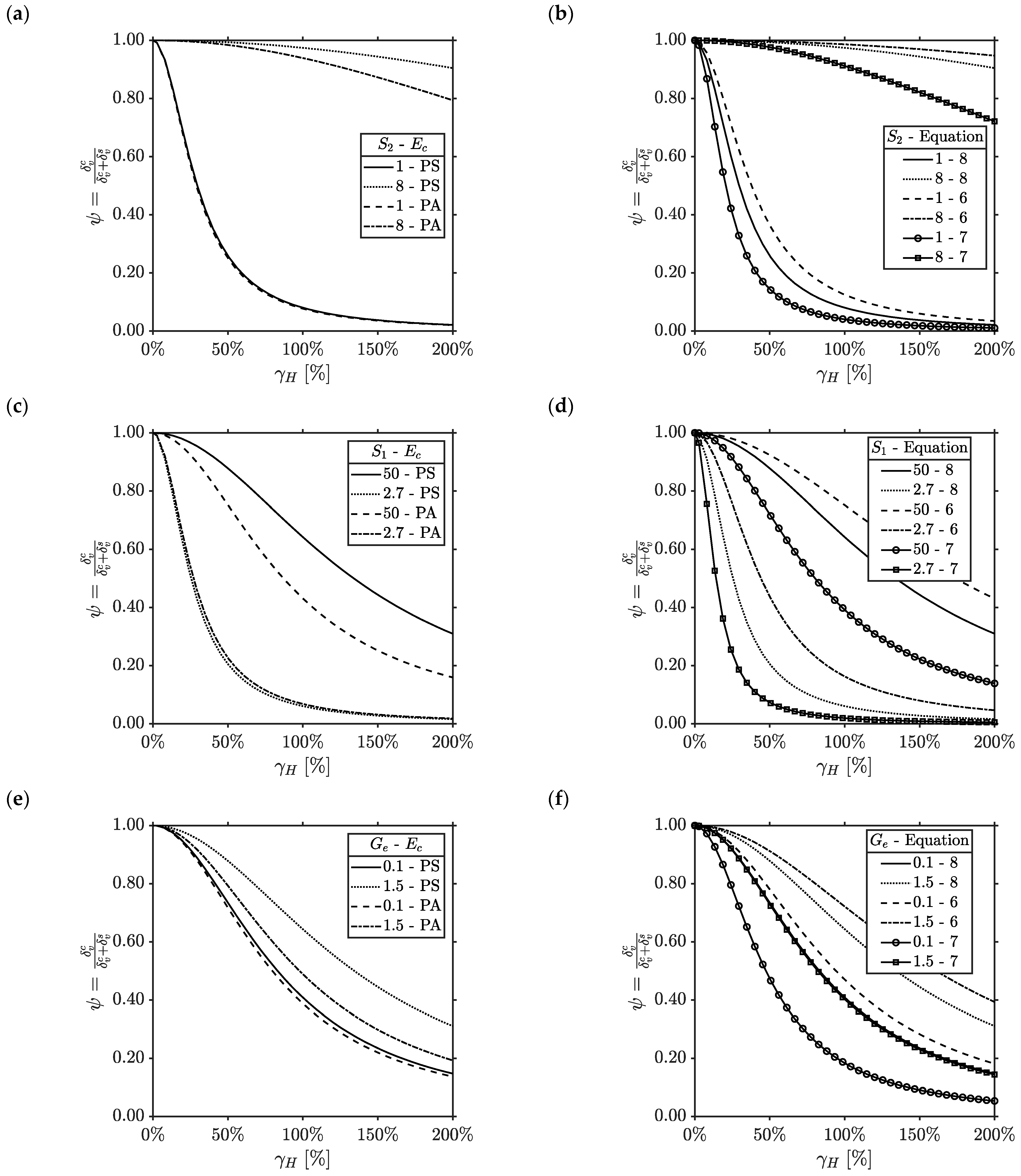
considering the two values of effective compressive modulus (Figure 2a,c,e) and the three values of the buckling load (Figure 2b,d,f) given in Section 2.1 and Section 2.2. Table 1, Table 2 and Table 3 report the percentage reductions of the ψ  function at four significant levels of shear strains, i.e., γ H = 50 % , γ H = 100 % , γ H = 150 % and γ H = 200 % , with the secondary shape factor, primary shape factor and shear modulus of the rubber, respectively. In each plot, a maximum level of shear strain equal to 200% was used, as this level of horizontal deformation approximately corresponds to the full-rollover threshold of the U-FREIs [53,54,55]. In Figure 3, the trends of the ψ function are shown for the limit values of the primary (Figure 3c,d) and secondary shape factor (Figure 3a,b), as well as the shear modulus of the rubber (Figure 3e,f), accounting for the different formulations for the effective compressive modulus (Figure 3a,c,e) and for the buckling load (Figure 3c,d,f).
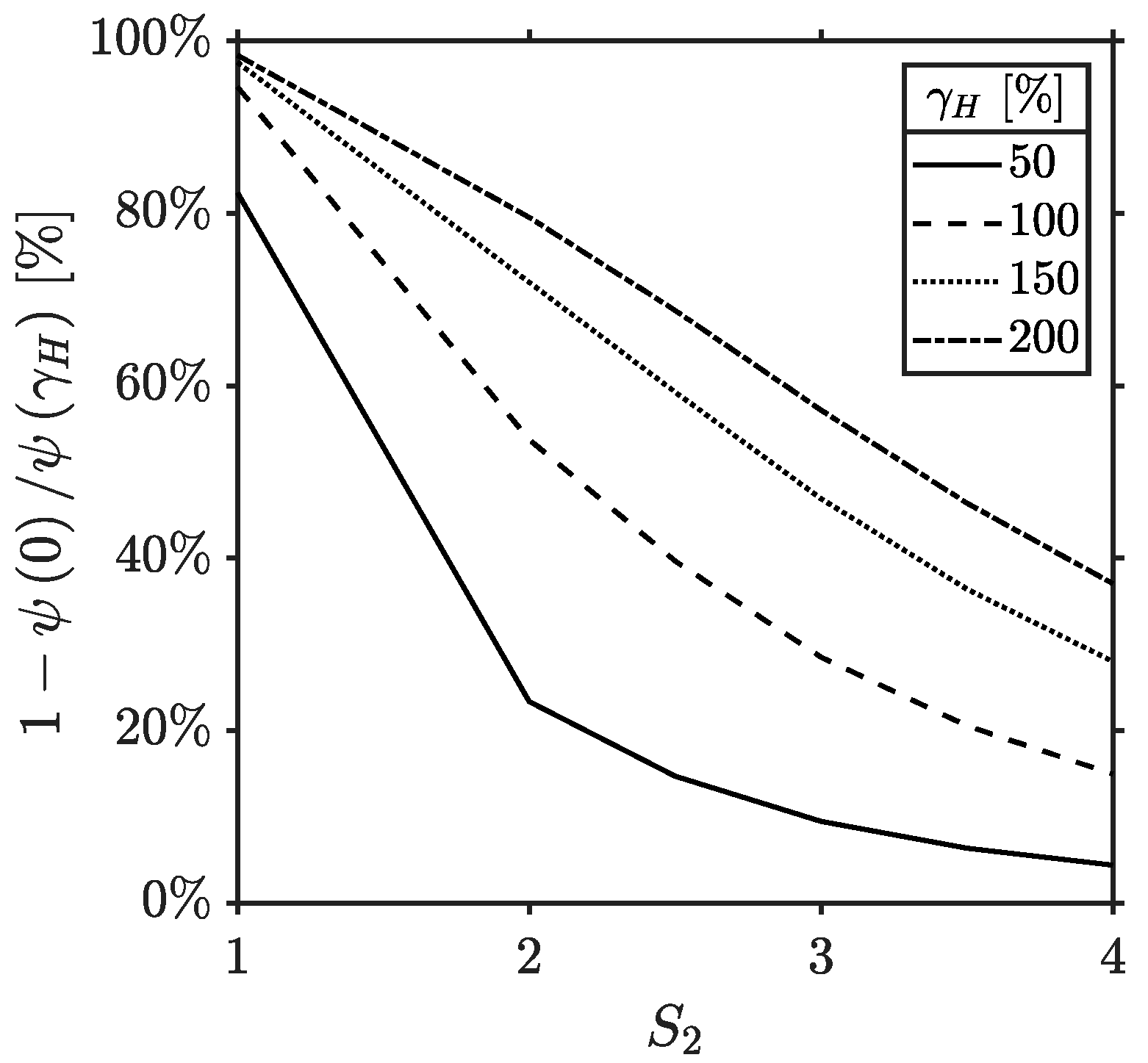
For low values of S 2 , ψ δ H greatly reduces, starting from relatively small shear strains, while for larger values of the secondary shape factors little reductions of the ψ function are obtained at large lateral deformations (Figure 2a,b). This function almost drops to zero for a combination of lower S 2 and larger γ H . Table 1 shows how the transition value of S 2 appears to be 2.5. For S 2 2.5 , a reduction of the order of 60.5% (on average on γ H ) is obtained, while for S 2 > 2.5 , the same reduction is of the order of 39%. This transition threshold matches that previously found for the stable/unstable response of U-FREIs under axial and shear load [15,17,18] and is also highlighted in Figure 4, where the percentage reductions of the ψ function with the secondary shape factor is shown at different levels of shear strain. This figure shows how, for relatively low values of the horizontal deformation, the vertical bearing capacity of the FREI is greatly reduced ( 1 ψ 0 / ψ γ H > 80 % ) when S 2 2.5 , while greater values of the secondary shape factors (i.e., S 2 > 2.5 3 ) ensure slight reductions of the vertical stiffness of the bearing ( 10 % < 1 ψ 0 / ψ γ H < 60 % ).
The primary shape factor appears to play a minor role in the shape of the ψ function with the shear strains, as a significant reduction of ψ δ H is obtained solely for S 1 5 (Figure 2c,d); the ψ function is almost constant with the primary shape factor at a generic shear strain threshold when S 1 > 5 (Table 2).
Larger values of the shear modulus of the rubber clearly increase the bearing capacity of the FREI. However, significant variation of the ψ  function at a generic shear strain level is obtained solely with great increases of G e (Figure 2e,f and Table 3).
Larger vertical deformations are expected with compressible rather than incompressible elastomeric layers. This is confirmed by Figure 2a,c,e where the surfaces obtained using E c δ H = 0 P A lay underneath those obtained with E c δ H = 0 P S . The influence of the effective compressive modulus at zero horizontal displacement is greater for larger values of the primary and secondary shape factors, as well as shear modulus of the rubber; thus, reductions of S 1 , S 2 or G e return values of the ψ function independent from the effective compressive modulus.
Finally, Equation (15) shows how the ψ  function is proportional to the buckling load of the bearing. Greater values of F v , c r (i.e., with rigid reinforcements) return a smaller reduction of ψ δ H with the shear strain (Figure 2b,d,f, Equations (6) and (8) in the legends).
Figure 2. Trends of the ψ function with the horizontal deformation and: (a,b) secondary shape factors; (c,d) primary shape factor; (e,f) shear modulus of the rubber.
Applsci 13 03515 g002
Figure 3. Range of variability of the ψ function with the horizontal deformation from maximum to minimum: (a,b) secondary shape factors; (c,d) primary shape factor; (e,f) shear modulus of the rubber.
Applsci 13 03515 g003
Figure 4. Percentage reductions of the ψ function with the secondary shape factors at different levels of shear strain.
Applsci 13 03515 g004

4. Finite Element Analyses

4.1. Description of the Finite Element Models

Validation of the analytical results through a parametric numerical study is presented in this section. Finite element analyses (FEAs) are carried out for a variety of strip-shaped U-FREIs with variable geometric and mechanical parameters. The trends of the ψ function are obtained from these analyses and compared to the analytical results.
Table 4 shows the set of FEMs, with the main geometric and mechanical parameters. A combination of six different base sides, total height, thickness of the elastomeric and fiber reinforcements layers lead to primary and secondary shape factors included in the ranges 5.5–22 and 1.0–4.0, respectively. In addition, six different values of the initial shear modulus of the rubber in the range 0.50–1.5 were considered. Combining six different base sides (Figure 5) with the imposed total height, the thickness of both elastomeric and fiber reinforcements layers lead to primary and secondary shape factors included in the ranges 5.5–22 and 1.0–4.0, respectively.
In all the FEMs, horizontal displacement is imposed on the top of the bearing up to a shear strain of 200%, as performed in Section 3.3.

4.2. Numerical Modeling

The finite element analyses were carried out using MSC.Marc/Mentat [56], a general-purpose FEA software optimized for non-linear analyses. Note that 2D plain strain finite element models (FEMs) were created for the analyses.
The elastomer was modeled using a compressible Neo-Hookean hyperelastic material model. The strain energy density function for a compressible generalized Rivlin model is described by the equation [57]:
W = p , q n C p , q I ¯ 1 3 p I ¯ 2 3 q + r = 1 m 1 D r J 1 2 r
being:
I ¯ 1 = J 2 / 3 I 1 I 1 = λ 1 2 + λ 2 2 + λ 3 2 I ¯ 2 = J 4 / 3 I 2 I 1 = λ 1 2 λ 2 2 + λ 2 2 λ 3 2 + λ 3 2 λ 1 2
with λ i as the principal stretches. I ¯ 1 and I ¯ 2 are the first and the second invariant of the unimodular component of the left Cauchy-Green deformation tensor B = F F T ; I 1 and I 2 are the first and the second invariant of the right Cauchy–Green deformation tensor C = F T F ; J = det F is the determinant of the deformation gradient F . C p q and D r are material constants related to the distortional response and the volumetric response, respectively.
For a compressible Neo-Hookean material, n = 1 ,   m = 1 ,   C 10 = C 1 ,   C 01 = 0 ,   C 11 = 0 , and Equation (18) reduces to:
W N H = C 1 I ¯ 1 3 2 ln J + D 1 J 1 2
For consistency with linear elasticity, it must be C 1 = G e / 2 and D 1 = K / 2 . In all FEMs, the bulk modulus of the rubber has been set equal to 2000 MPa. This simplified material model allows for a direct design of the material properties of the rubber layers, as a single parameter is needed when considering these layers as incompressible. Multi-parameters hyperelastic material models may be used to account for the complex response of the rubber, such as viscous behavior. The fiber reinforcement is modeled with a linear elastic isotropic material, fully defined by two parameters: the Young’s modulus E f and the thickness t f .
The elastomer is modeled with arbitrary quadrilateral plane strain with the Hermann formulation element (element 80 in Marc [58]). It is a four-node, isoparametric element written for plane strain incompressible applications. This element uses bilinear interpolation functions, and the strains tend to be constant throughout the element; therefore, a fine mesh is needed. The stiffness is formed using four-point Gaussian integration. This element is preferred over higher-order elements when used in a contact analysis. The reinforcement is modeled with a four-node plane strain rebar element (element 143 in Marc [58]). It is an isoparametric, four-node hollow quadrilateral element, in which a single strain member (such as a reinforcing rod or s cord) could be placed. The element is then used in conjunction with the four-node plane strain continuum element of the rubber to represent cord-reinforced composite materials.
Considering that a value of friction coefficient equal to 1 has been found reasonable to prevent slip and to fully develop contact pressure between rubber layer and typical steel supports [59], a Coulomb friction coefficient equal to 0.9 has been set in all the FEMs. Thus, the bearing could detach from the support to simulate the unbonded configuration.

4.3. Numerical Results

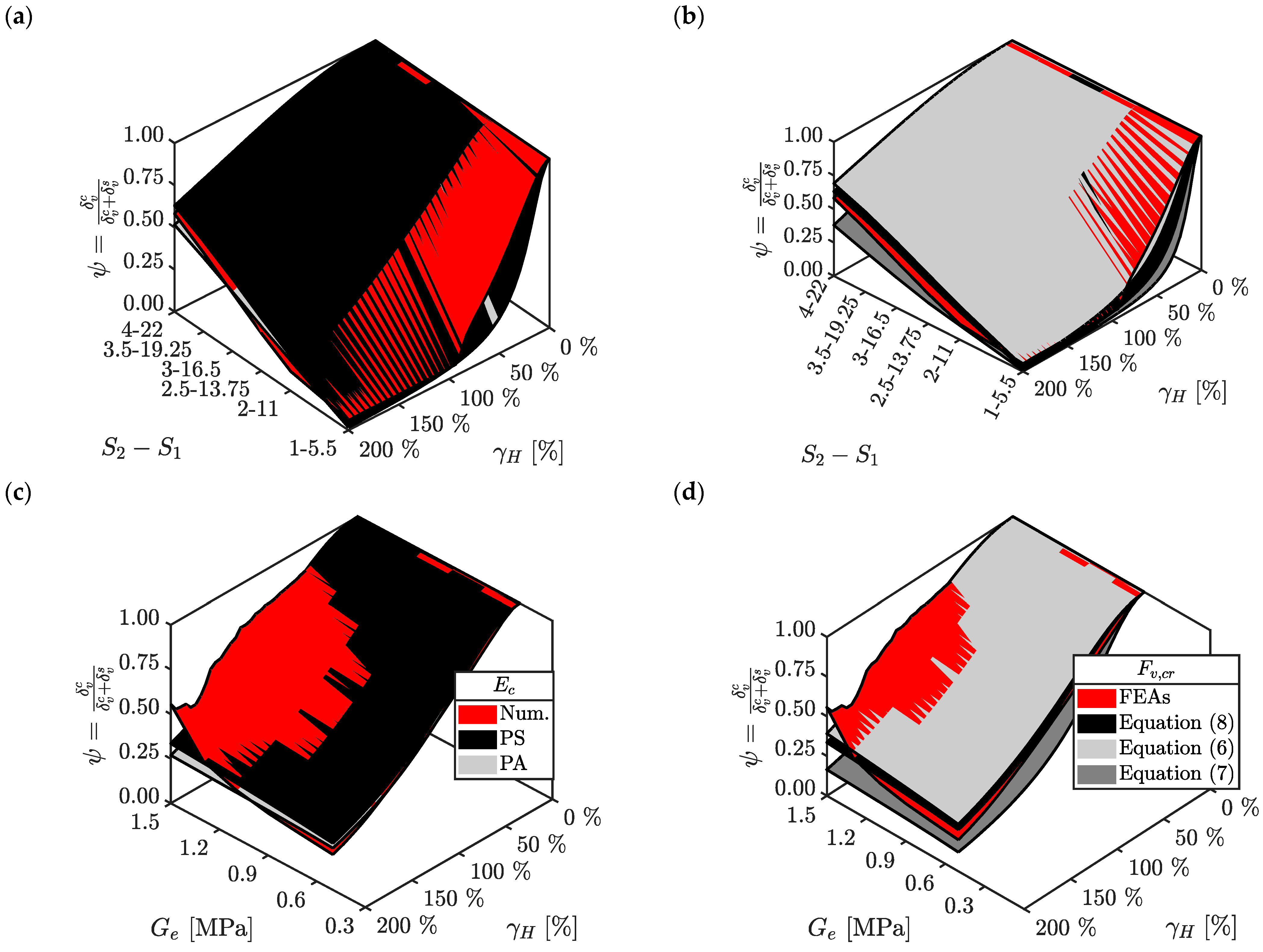
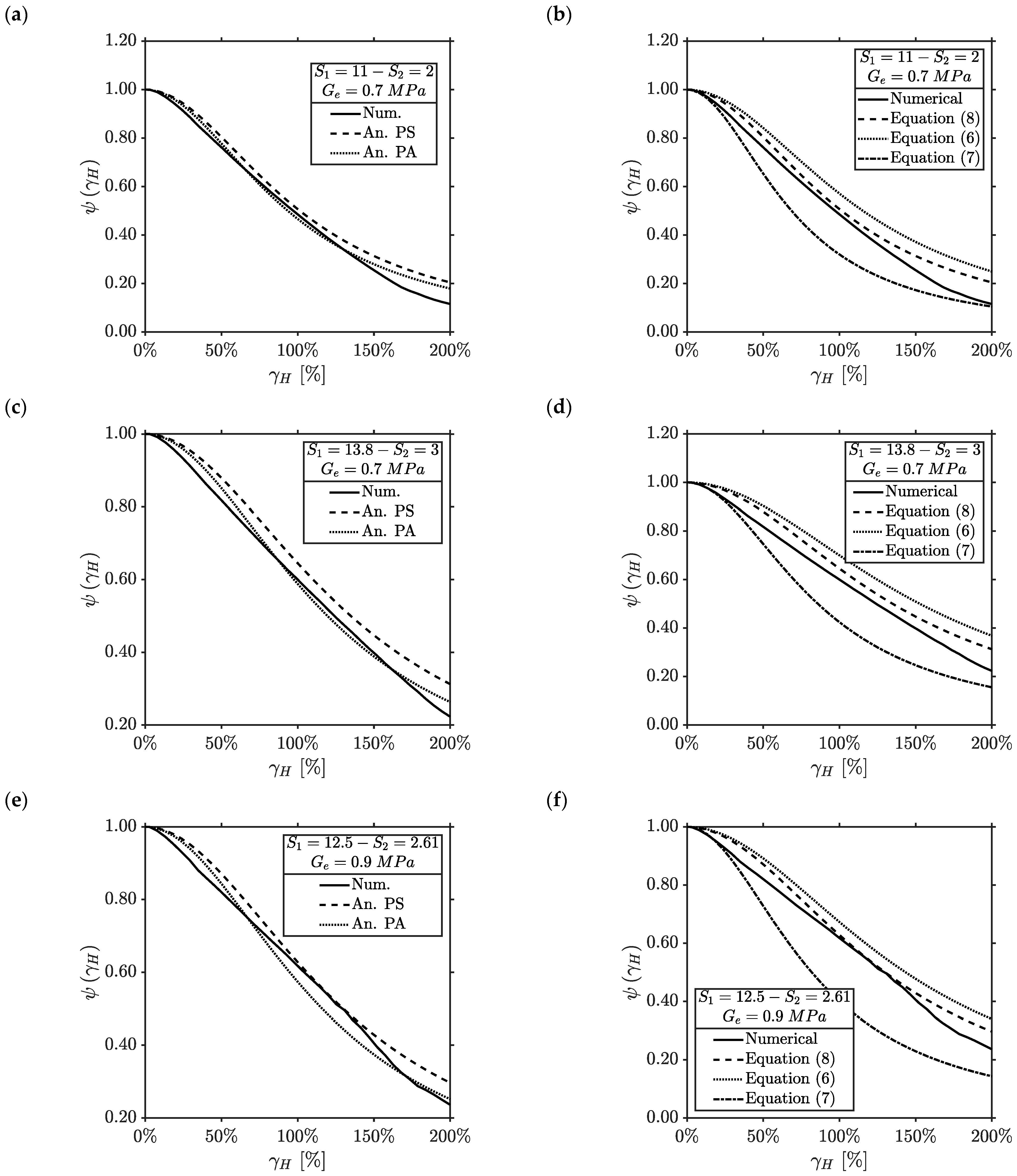
In Figure 6, analytical–numerical comparisons on the trends of the ψ  function with the shear strain are shown for the different values of the primary and secondary shape factors (Figure 6a,b) and shear modulus of the rubber (Figure 6c,d). In each graph, the numerical results are compared with the analytical ones obtained considering the different approaches for the effective compressive modulus (Figure 6a,c) and for the buckling load (Figure 6b,d). In Figure 7, a focus on the trends of the ψ function with the shear strain and some values of the primary (Figure 7c,d), secondary shape factors (Figure 7a,b) and the shear modulus of the rubber (Figure 7e,f), are shown. These figures highlight the good agreement between numerical and analytical results, with the proposed analytical formulation able to predict the reduction of the vertical stiffness with increasing horizontal deformations.
The numerical results confirm the trends of the ψ  function with the main geometric and mechanical parameters of the U-FREIs as:
  • Great reductions of ψ δ H with the horizontal deformation are related to smaller values of the primary and secondary shape factor (Figure 6a,b). When S 2 = 1.0 ( S 1 = 5.5 ), the ψ  function drops in a reduced range of shear strain (i.e., γ H 50 % ), while for S 2 = 4.0 ( S 1 = 22 ), the minimum value of ψ δ H is around 0.5 at γ H = 200 % .
  • The shear modulus of the rubber plays a minor role compared to the geometric parameters of the U-FREI (Figure 6c,d). A good agreement is found between numerical and analytical results, but for larger values of G e , the numerical trends return increasing values of ψ δ H . This is the effect of the full-rollover condition that is prominent for hard rather than soft compounds. Equation (15) does not take into account this phenomenon.
From Figure 6a,d, it can be seen how the pressure approach fits the numerical results with good agreement at smaller levels of S 1 S 2 and G e , while increasing these factors, the best fitting is obtained with the pressure solution. As for the buckling load, the best agreements were found using Equation (8), while Equations (6) and (7) appear to underestimate and overestimate, respectively, the ψ δ H trends.
The influence of the different analytical models for the effective compressive modulus and for the buckling load was studied in terms of percentage difference between numerical models and analytical predictions, defined as:
E B p = abs ψ γ ¯ H | n u m ψ γ ¯ H , E ¯ c , F ¯ v , c r | a n ψ γ ¯ H , E ¯ c , F ¯ v , c r | a n × 100
where E B p is the difference referred to a generic bearing’s parameter (e.g., shear modulus, primary or secondary shape factor), ψ γ ¯ H | n u m is the ψ  function at γ ¯ H obtained from the numerical analyses, and ψ γ ¯ H | a n is the ψ  function calculated with Equation (15) at γ ¯ H , with either one of the effective compressive moduli ( E ¯ c ) and buckling loads ( F ¯ v , c r ) equations proposed in Section 2. Similar to Section 3.3, four shear strain thresholds are considered, namely γ H = 50 % , γ H = 100 % , γ H = 150 % and γ H = 200 % . Figure 8a reports the average percentage difference between analytical and numerical models with different values of the shear modulus of the rubber ( E G e ), while Figure 8b illustrates the differences between models with variable primary and secondary shape factors ( E S 1 , 2 ).
The minimum percentage difference between analytical and numerical results is obtained when using the pressure approach for the effective compressive modulus and Equation (7) for the buckling load. At γ H = 50 % , this combination returns differences of the order of 2.59% and 6.91% as averages on G e and S 1 , 2 , respectively; at γ H = 100 % , γ H = 150 % and γ H = 200 % , these differences become 11.0%, 16.1% and 18.6%, as averages on G e , and 10%, 7.41% and 17.8% as averages on S 1 , 2 .
The analytical–numerical accuracy reduces when using the pressure approach for E c and Equation (7) for F v , c r as the percentage differences between numerical and analytical results are:
  • γ H = 50 % : 36.3% (average on G e ) and 30.2% (average on S 1 , 2 );
  • γ H = 100 % : 45.9% (average on G e ) and 28.3% (average on S 1 , 2 );
  • γ H = 150 % : 57.0% (average on G e ) and 47.1% (average on S 1 , 2 );
  • γ H = 200 % : 56.7% (average on G e ) and 48.4% (average on S 1 , 2 ).
These reductions depend on the assumption at the basis of this equation, as the elastomer is considered incompressible and the reinforcement flexible. In these conditions, the vertical bearing capacity of the device is minimally influenced by the geometric and mechanical parameters compared to FREIs with soft compound and flexible reinforcements. However, as Equation (7) returns greater reductions of the analytical trends of ψ δ H compared to the numerical results, this equation can be used in a design phase as first estimate of the vertical stiffness reduction due to horizontal deformation of the U-FREI.

5. Conclusions

This paper introduced an analytical method to derive the vertical stiffness of fiber reinforced elastomeric isolators subjected to both axial and shear loads.
A novel function has been introduced through this work to account for the increased vertical deformation of the elastomeric bearings following the horizontal displacement: the ψ  function. This function, defined as the ratio between the vertical displacement under pure compression and the total vertical displacement (i.e., vertical displacement due to axial and shear loads), assumes values lower than one and reduces the vertical capacity of the bearings when displaced in the horizontal direction.
The trends of the ψ  function with the main geometric and mechanical parameters of the FREI, namely the primary and secondary shape factors, as well as the shear modulus of the rubber, have been proposed. Different analytical approaches to compute the effective compressive modulus under pure compression and the buckling load of the bearings have been considered to investigate the influence of the different hypotheses used in the analytical studies. Better accuracy was obtained between analytical and numerical results when using the pressure solution for the effective compressive modulus and considering the reinforcement as rigid, with a maximum percentage difference of the order of 10% for a shear strain equal to 0.50. It has been seen how the secondary shape factor greatly affects the reduction of the vertical bearing capacity of the FREI. When this parameter assumes values lower than 2.5, the ψ  function rapidly decreases with the shear strain, and so does the vertical stiffness of the U-FREI. The shear modulus and the primary shape factor affects the shape of the ψ  function mainly when a great increase or decrease is operated on these parameters.
The ψ  function has also been evaluated through a parametric finite element analysis on U-FREIs with different mechanical and geometric parameters. The numerical analyses validated the trends of the ψ  function, showing how the proposed analytical method can be adequately adopted to estimate the vertical stiffness and the effective compressive modulus of U-FREIs under combined axial and shear loads.
The results presented in this paper may be extended, considering different material models for the rubber, as well as variable mechanical properties of the reinforcements.

Author Contributions

S.G.: conceptualization, methodology, software, investigation, resources, writing—original draft; A.C.: resources, writing—review and editing, supervision. All authors have read and agreed to the published version of the manuscript.

Funding

This research did not receive any specific grant from funding agencies in the public, commercial, or not-for-profit sectors.

Institutional Review Board Statement

Not applicable.

Informed Consent Statement

Not applicable.

Data Availability Statement

The data presented in this study are available on request from the corresponding author.

Conflicts of Interest

The authors declare that they have no known competing financial interest or personal relationships that could have appeared to influence the work reported in this paper.

References

  1. Moon, B.Y.; Kang, G.J.; Kang, B.S.; Kelly, J.M. Design and manufacturing of fiber reinforced elastomeric isolator for seismic isolation. J. Mater. Process. Technol. 2002, 130, 145–150. [Google Scholar] [CrossRef]
  2. Crozier, W.F.; Stoker, J.R.; Martin, V.C.; Nordlin, E.F. A laboratory evaluation of full size elastomeric bridge baring pads. Transp. Res. Rec. 1975, 547, 55–58. [Google Scholar]
  3. Kelly, J.M. Analysis of fiber-reinforced elastomeric isolators. Int. J. Solids Struct. 1999, 2, 19–34. [Google Scholar]
  4. De Luca, A.; Guidi, L.G. State of art in the worldwide evolution of base isolation design. Soil Dyn. Earthq. Eng. 2019, 125, 105722. [Google Scholar] [CrossRef]
  5. Kelly, J.M. Analysis of the run-in effect in fiber-reinforced isolators under vertical load. J. Mech. Mater. Struct. 2008, 3, 1383–1401. [Google Scholar] [CrossRef] [Green Version]
  6. Ashkezari, G.D.; Aghakouchak, A.A.; Kokabi, M. Design, manufacturing and evaluation of the performance of steel like fiber reinforced elastomeric seismic isolators. J. Mater. Process. Technol. 2008, 197, 140–150. [Google Scholar] [CrossRef]
  7. Toopchi-Nezhad, H.; Tait, M.J.; Drysdale, R.G. Bonded versus unbonded strip fiber reinforced elastomeric isolators: Finite element analysis. Compos. Struct. 2011, 93, 850–859. [Google Scholar] [CrossRef]
  8. Kelly, J.M.; Konstantinidis, D.A. Mechanics of Rubber Bearings for Seismic and Vibration Isolation; John Wiley & Sons, Ltd.: Hoboken, NJ, USA, 2011. [Google Scholar]
  9. Toopchi-Nezhad, H.; Tait, M.J.; Drysdale, R.G. Testing and modeling of square carbon fiber-reinforced elastomeric seismic isolators. Struct. Control Health Monit. 2007, 15, 876–900. [Google Scholar] [CrossRef]
  10. Madera Sierra, I.E.; Losanno, D.; Strano, S.; Marulanda, J.; Thomson, P. Development and experimental behavior of HDR seismic isolators for low rise residential buildings. Eng. Struct. 2019, 183, 894–906. [Google Scholar] [CrossRef]
  11. Vaiana, N.; Losanno, D.; Ravichandran, N. A novel family of multiple springs models suitable for biaxial rate-independent hysteretic behavior. Comput. Struct. 2021, 244, 106403. [Google Scholar] [CrossRef]
  12. Vaiana, N.; Rosati, L. Classification and unified phenomenological modeling of complex uniaxial rate-independent hysteretic responses. Mech. Syst. Signal Process. 2023, 182, 109539. [Google Scholar] [CrossRef]
  13. Toopchi-Nezhad, H.; Tait, M.J.; Drysdale, R.G. Lateral Response Evaluation of Fiber-Reinforced Neoprene Seismic Isolators Utilized in an Unbonded Application. J. Struct. Eng. 2008, 134, 1627–1637. [Google Scholar] [CrossRef]
  14. Toopchi-Nezhad, H.; Drysdale, R.G.; Tait, M.J. Parametric Study on the Response of Stable Unbonded-Fiber Reinforced Elastomeric Isolators (SU-FREIs). J. Compos. Mater. 2009, 43, 1569–1587. [Google Scholar] [CrossRef]
  15. De Raaf, M.G.; Tait, M.J.; Toopchi-Nezhad, H. Stability of fiber-reinforced elastomeric bearings in an unbonded application. J. Compos. Mater. 2011, 45, 1873–1884. [Google Scholar] [CrossRef]
  16. UNI EN 1998-1:2013; Part 1: General Rules, Seismic Actions and Rules for Buildings. UNI Ente Italiano di Normazione: Milano, Italy, 2013.
  17. Galano, S.; Losanno, D.; Calabrese, A. Stability analysis of unbonded fiber reinforced isolators of square shape. Eng. Struct. 2021, 245, 112846. [Google Scholar] [CrossRef]
  18. Galano, S.; Calabrese, A.; Losanno, D. On the response of fiber reinforced elastomeric isolators (FREIs) under bidirectional shear loads. Structures 2021, 34, 2340–2354. [Google Scholar] [CrossRef]
  19. Galano, S.; Calabrese, A.; Losanno, D.; Serino, G.; Strano, S. Tuning the lateral response of unbonded fiber reinforced elastomeric isolators (U-FREIs) through horizontal holes: Experimental and numerical findings. Compos. Struct. 2022, 289, 115454. [Google Scholar] [CrossRef]
  20. Orfeo, A.; Tubaldi, E.; Muhr, A.H.; Losanno, D. Mechanical behaviour of rubber bearings with low shape factor. Eng. Struct. 2022, 266, 114532. [Google Scholar] [CrossRef]
  21. De Domenico, D.; Losanno, D.; Vaiana, N. Experimental tests and numerical modeling of full-scale unbonded fiber reinforced elastomeric isolators (UFREIs) under bidirectional excitation. Eng. Struct. 2023, 274, 115118. [Google Scholar] [CrossRef]
  22. Losanno, D.; De Domenico, D.; Madera-Sierra, I.E. Experimental testing of full-scale fiber reinforced elastomeric isolators (FREIs) in unbonded configuration. Eng. Struct. 2022, 260, 114234. [Google Scholar] [CrossRef]
  23. Losanno, D.; Ravichandran, N.; Parisi, F.; Calabrese, A.; Serino, G. Seismic performance of a Low-Cost base isolation system for unreinforced brick Masonry buildings in developing countries. Soil Dyn. Earthq. Eng. 2021, 141, 106501. [Google Scholar] [CrossRef]
  24. Losanno, D.; Ravichandran, R.; Parisi, F. Seismic fragility models for base-isolated unreinforced masonry buildings with fibre-reinforced elastomeric isolators. Earthq. Eng. Struct. Dyn. 2023, 52, 308–334. [Google Scholar] [CrossRef]
  25. Losanno, D.; Ravichandran, N.; Parisi, F. Seismic fragility of base-isolated single-storey unreinforced masonry buildings equipped with classical and recycled rubber bearings in Himalayan region. J. Build. Eng. 2022, 45, 103648. [Google Scholar] [CrossRef]
  26. Losanno, D.; Calabrese, A.; Madera-Sierra, I.E.; Spizzuoco, M.; Marulanda, J.; Thomson, P.; Serino, G. Recycled versus Natural-Rubber Fiber-Reinforced Bearings for Base Isolation: Review of the Experimental Findings. J. Earthq. Eng. 2020, 26, 1921–1940. [Google Scholar] [CrossRef]
  27. Cilento, F.; Losanno, D.; Piga, L. An experimental study on a novel reclaimed rubber compound for fiber-reinforced seismic isolators. Structures 2022, 45, 9–22. [Google Scholar] [CrossRef]
  28. Kelly, J.M. Earthquake-Resistant Design with Rubber; Springer: London, UK, 1996. [Google Scholar]
  29. Losanno, D.; Madera Sierra, I.E.; Spizzuoco, M.; Marulanda, J.; Thomson, P. Experimental assessment and analytical modeling of novel fiber-reinforced isolators in unbounded configuration. Compos. Struct. 2019, 212, 66–82. [Google Scholar] [CrossRef]
  30. Galano, S. Vertical response of unbonded fiber reinforced elastomeric isolators (U-FREIs) under bidirectional shear loading. Front. Built Environ. 2022, 8, 265. [Google Scholar] [CrossRef]
  31. Losanno, D.; Madera Sierra, I.E.; Spizzuoco, M.; Marulanda, J.; Thomson, P. Experimental performance of unbonded polyester and carbon fiber reinforced elastomeric isolators under bidirectional seismic excitation. Eng. Struct. 2022, 209, 110003. [Google Scholar] [CrossRef]
  32. Riascos, C.; Klopov, S.; Losanno, D.; Marulanda, J.; Thomson, P. Real-time hybrid simulations including rocking effects: The caso of a frame-structure with unbonded elastomeric isolators. Struct. Control Health Monit. 2022, 29, e2984. [Google Scholar] [CrossRef]
  33. Tsai, H.C.; Kelly, J.M. Stiffness Analysis of Fiber-Reinforced Elastomeric Isolators; PEER Report 05; Pacific Earthquake Engineering Research Center, College of Engineering, University of California Berkeley: Berkeley, CA, USA, 2001. [Google Scholar]
  34. Tsai, H.C. Compression stiffness of infinite-strip bearings of laminated elastic material interleaving with flexible reinforcements. Int. J. Solids Struct. 2004, 41, 6647–6660. [Google Scholar] [CrossRef]
  35. Tsai, H.C. Compression stiffness of circular bearings of laminated elastic material interleaving with flexible reinforcements. Int. J. Solids Struct. 2006, 43, 3484–3497. [Google Scholar] [CrossRef] [Green Version]
  36. Kelly, J.M.; Calabrese, A. Mechanics of Fiber Reinforced Bearings; PEER Report 101; Pacific Earthquake Engineering Research Center, College of Engineering, University of California Berkeley: Berkeley, CA, USA, 2012. [Google Scholar]
  37. Angeli, P.; Russo, G.; Paschini, A. Carbon fiber-reinforced rectangular isolators with compressible elastomer: Analytical solution for compression and bending. Int. J. Solids Struct. 2013, 50, 3519–3527. [Google Scholar] [CrossRef] [Green Version]
  38. Kelly, J.M.; Van Engelen, N.C. Single Series Solution for the Rectangular Fiber-Reinforced Elastomeric Isolator Compression Modulus; Headquarters at the University of California, Pacific Earthquake Engineering Research Center: Berkeley, CA, USA, 2015. [Google Scholar]
  39. Pinarbasi, S.; Mengi, Y. Elastic layers bonded to flexible reinforcements. Int. J. Solids Struct. 2008, 45, 794–820. [Google Scholar] [CrossRef] [Green Version]
  40. Kelly, J.M. Tension Buckling in Multilayer Elastomeric Bearings. J. Eng. Mech. 2003, 129, 1363–1368. [Google Scholar] [CrossRef]
  41. Naeim, F.; Kelly, J.M. Design of Seismic Isolated Structures: From Theory to Practice; John Wiley & Sons, Inc.: New York, NY, USA, 1999. [Google Scholar]
  42. Kelly, J.M.; Marsico, M.R. Stability and post-buckling behavior in nonbolted elastomeric isolators. J. Anti-Seism. Syst. Int. Soc. 2010, 1, 41–54. [Google Scholar] [CrossRef] [Green Version]
  43. Calabrese, A.; Spizzuoco, M.; Galano, S.; Tran, N.; Strano, S.; Terzo, M. A parametric study on the stability of fiber reinforced rubber bearings under combined axial and shear loads. Eng. Struct. 2021, 2021, 111441. [Google Scholar] [CrossRef]
  44. Kelly, J.M.; Takhirov, S. Analytical and Numerical Study on Buckling of Elastomeric Bearings with Various Shape Factors; Earthquake Engineering Research Center, University of California: Berkeley, CA, USA, 2004. [Google Scholar]
  45. Tsai, H.H.; Kelly, J.M. Buckling load of seismic isolators affected by flexibility of reinforcement. Int. J. Solids Struct. 2005, 42, 255–269. [Google Scholar] [CrossRef]
  46. Tsai, H.H.; Kelly, J.M. Buckling of short beams with warping effect included. Int. J. Solids Struct. 2005, 42, 239–253. [Google Scholar] [CrossRef]
  47. Peng, T.B.; Li, J.Z.; Fan, L.C. Pilot Study on the Horizontal Shear Behavior of FRP Rubber Isolators; Asia-Pacific Conference on FRP in Structures (APFIS 2007); International Institute for FRP in Construction: Winnipeg, MB, Canada, 2007. [Google Scholar]
  48. Gerharer, U.; Strauss, A.; Bergmeister, K. Verbesserte Bemessungsrichtlinien für Bewehrte Elastomerlager. Bautechnik 2011, 88, 451–458. [Google Scholar] [CrossRef]
  49. Russo, G.; Pauletta, M.; Cortesia, A. A study on experimental shear behavior of fiber-reinforced elastomeric isolators with various fiber layouts, elastomers and aging conditions. Eng. Struct. 2013, 52, 422–433. [Google Scholar] [CrossRef]
  50. Toopchi-Nezhad, H. Horizontal stiffness solutions for unbonded fiber reinforced elastomeric bearings. Struct. Eng. Mech. 2014, 49, 395–410. [Google Scholar] [CrossRef]
  51. Van Engelen, N.C.; Tait, M.J.; Konstantinidis, D. Model of the Shear Behavior of Unbonded Fiber-Reinforced Elastomeric Isolators. J. Struct. Eng. 2015, 141, 04014169. [Google Scholar] [CrossRef]
  52. Van Ngo, T.; Dutta, A.; Deb, S.K. Evaluation of horizontal stiffness of fibre-reinforced elastomeric isolators. Earthq. Eng. Struct. Dyn. 2017, 46, 1747–1767. [Google Scholar] [CrossRef]
  53. Konstantinidis, D.; Kelly, J.M.; Makris, N. Experimental Investigations on the Seismic Response of Bridge Bearings; PEER Report 2008/02; Pacific Earthquake Engineering Research Center, College of Engineering, University of California Berkeley: Berkeley, CA, USA, 2008. [Google Scholar]
  54. UNI EN 15129:2018; Comité Européen de Normalisation TC 340, Anti-Seismic Devices. European Committee for Standardization CEN: Brussels, Belgium, 2018.
  55. Furinghetti, M.; Pavese, A. Equivalent Uniaxial Accelerogram for CSS-Based Isolation Systems Assessment under Two-Components Seismic Events. Mech. Based Des. Struct. Mach. 2017, 45, 282–295. [Google Scholar] [CrossRef]
  56. MSC. Software Corporation. MSC.Marc Mentat Release Guide; MSC. Software Corporation: Santa Ana, CA, USA, 2005. [Google Scholar]
  57. MSC. Software Corporation. MAR103 Experimental Elastomer Analysis; MSC. Software Corporation: Santa Ana, CA, USA, 2017. [Google Scholar]
  58. MSC. Software Corporation. Volume B: Element Library; MSC. Software Corporation: Santa Ana, CA, USA, 2017. [Google Scholar]
  59. Kelly, J.M.; Konstantinidis, D. Effect of Friction on Unbonded Elastomeric Bearings. J. Eng. Mech. 2009, 135, 953–960. [Google Scholar] [CrossRef]
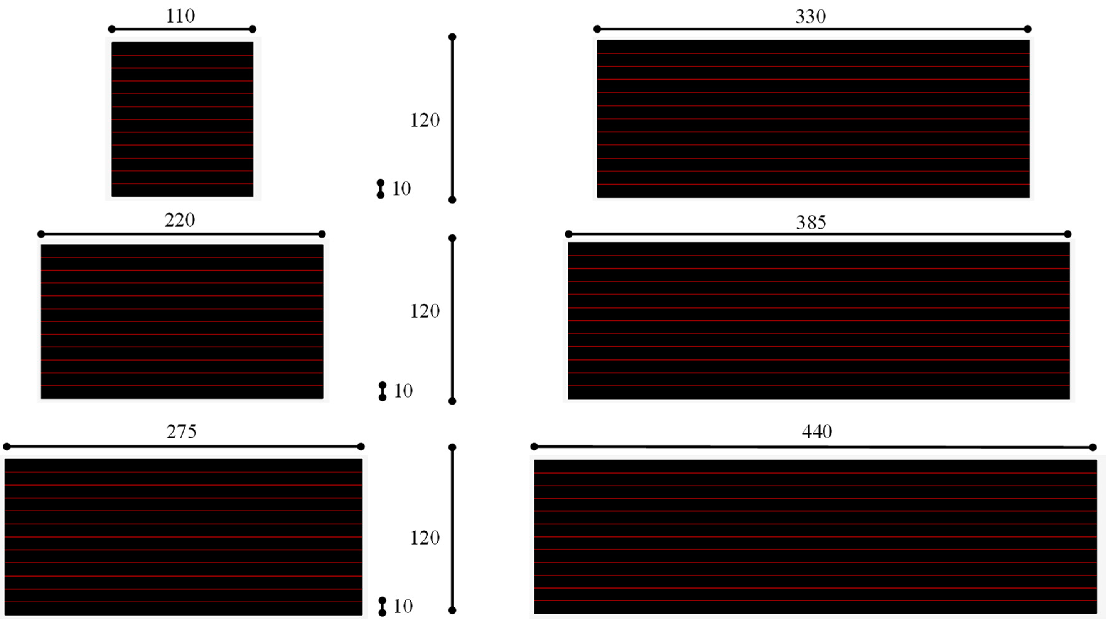
Figure 5. FEMs of the FREIs with different geometries (dimensions are in mm).
Applsci 13 03515 g005
Figure 6. Analytical numerical comparison on the trends of the ψ function with the shear strain and: (a,b) primary and secondary shape factors; (c,d) shear modulus of the rubber.
Applsci 13 03515 g006
Figure 7. The 2D analytical vs. numerical trends of the ψ function for different values of the primary (c,d) and secondary (a,b) shape factors and of the shear modulus of the rubber (e,f).
Applsci 13 03515 g007
Figure 8. Percentage difference between analytical and numerical models on the ψ function at four different levels of shear strain and: (a) shear modulus of the rubber; (b) primary and secondary shape factors.
Applsci 13 03515 g008
Table 1. Percentage reduction of the ψ  function with the shear strain for different values of the secondary shape factor.
S 2 1 ψ γ H = 50 % 1 ψ γ H = 100 % 1 ψ γ H = 150 % 1 ψ γ H = 200 %
174.6%91.8%96.4%97.9%
225.6%56.6%75.6%84.3%
310.3%30.4%50.9%64.3%
44.80%16.1%31.2%44.0%
52.53%8.95%18.9%28.8%
61.48%5.39%11.9%19.0%
70.955%3.53%7.99%13.1%
80.673%2.50%5.74%9.54%
Table 2. Percentage reduction of the ψ  function with the shear strain for different values of the primary shape factor.
S 1 1 ψ γ H = 50 % 1 ψ γ H = 100 % 1 ψ γ H = 150 % 1 ψ γ H = 200 %
2.779.9%93.8%97.3%98.4%
3.157.7%83.8%92.5%95.5%
3.743.9%74.8%87.6%92.4%
4.535.6%67.7%83.3%89.6%
5.930.4%62.4%79.8%87.2%
8.326.9%58.2%76.8%85.1%
1423.5%53.8%73.5%82.7%
5012.5%35.2%56.3%69.0%
Table 3. Percentage reduction of the ψ  function with the shear strain for different values of the shear modulus of the rubber.
G e [ MPa ] 1 ψ γ H = 50 % 1 ψ γ H = 100 % 1 ψ γ H = 150 % 1 ψ γ H = 200 %
0.1027.1%58.5%77.0%85.3%
0.3021.3%50.7%70.9%80.8%
0.5018.7%46.6%67.4%78.2%
0.7016.8%43.4%64.5%75.9%
0.9015.4%40.8%62.0%73.9%
1.114.2%38.5%59.8%72.0%
1.313.2%36.7%57.9%70.4%
1.512.5%35.1%56.2%68.9%
Table 4. Overview of the geometric and mechanical parameters used for the parametric FEAs.
2aH t e t f S 1 S 2 G e
[mm][mm][mm][mm][-][-][MPa]
11012010.01.005.5001.000.500
220 11.002.000.700
275 13.752.500.900
330 16.503.001.10
385 19.253.501.30
440 22.004.001.50
Disclaimer/Publisher’s Note: The statements, opinions and data contained in all publications are solely those of the individual author(s) and contributor(s) and not of MDPI and/or the editor(s). MDPI and/or the editor(s) disclaim responsibility for any injury to people or property resulting from any ideas, methods, instructions or products referred to in the content.