Article

Numerical Analysis of Shield Tunnelling Breakthrough Working Shaft by Artificial Ground Freezing Method under Extreme Conditions Considering Phase Change Latent Heat

1
Department of Underground Engineering, Nanjing Tech University, Nanjing 210009, China
2
Research Center of Coastal and Urban Geotechnical Engineering, Zhejiang University, Hangzhou 310058, China
*
Author to whom correspondence should be addressed.
Appl. Sci. 2023, 13(6), 3651; https://doi.org/10.3390/app13063651
Submission received: 24 November 2022 / Revised: 6 March 2023 / Accepted: 10 March 2023 / Published: 13 March 2023

Abstract

:
The artificial ground freezing method has been widely used in shield tunneling breakthrough working shafts. The freezing effect was mainly considered in the previous research, and the heat generation of the shield machine was not considered, which has great influence in actual engineering. In this paper, a coupling calculation model, considering phase change latent heat, is establishes that by containing the freezing process and heat generation of the shield machine, the model is verified. A numerical simulation is carried out for several working conditions that may occur in actual projects, and the following conclusions are obtained. Although the heat dissipated by the normal tunneling of the shield machine will melt the frozen soil curtain that originally meets the design requirements, the thickness of the frozen soil curtain after melting cannot reach the initial design, though it is still within the safe range. In the process of a continuous rotation working condition, the bottom and sides of a cup-shaped frozen soil curtain are partially melted in the early 6 day stay of the shield machine, and the thickness is reduced to a relatively stable value of 0.8 m. In a temporary shutdown working condition, when the contact surface temperature between the shield machine shell and the frozen soil drops to −12 °C after almost 4 days of shutdown, the shield machine may not keep tunneling forward due to the freezing effect. The research results will benefit the freezing design and management of the shield tunneling breakthrough working shaft under extreme conditions.

1. Introduction

Ground space resources are increasingly tense, and the development of metro tunnels is the general trend. Due to its high automation, fast construction speed, and little influence on ground disturbance, the shield method is widely used in metro tunnels [1]. The experience of shield tunneling construction in the past shows that the construction of the shield tunnel breakthrough working shaft undoubtedly is a high-risk stage [2,3]. This is especially true for soft soil geological conditions and soil that is rich in water, and improper construction due to the influence of groundwater may cause water gushing and sand gushing at the portal, resulting in a series of consequences, such as economic losses, delays in the construction period, and ground surface settlement. Therefore, the water sealing effect of the support system is even more important [4]. Usually, some conventional construction methods, such as the deep mixing method, grouting method, high-pressure rotary spraying method, and precipitation method are used to strengthen the soil around the working shaft [5]. Generally, when the conventional reinforcement method is completed, and serious sand and water gushing phenomena sometimes appears in the stage of breakthrough working shaft, in order to ensure the safety of the breakthrough stage, artificial ground freezing technology (AGF) is often used for auxiliary reinforcement [6]. Compared with other soil reinforcement methods, the AGF method has the advantages of good reinforcement uniformity, high strength, a good water sealing effect, safety and environmental protections, and the reinforcement process and effect can be monitored during the construction. It has been widely used in the working shaft construction of shield tunnel [7]. At present, the AGF has a rich theoretical basis and engineering practice experience, such as the freezing-sealing pipe roof method applied to the century projects of the Gongbei tunnel of the Hongkong–Zhuhai–Macau Bridge [8].
The key to the successful application of the AGF construction method lies in the stability of the frozen soil curtain. The temperature field is the most critical control index for AGF method. In order to grasp the development of the frozen soil curtain during construction, the temperature monitoring data are usually used to invert the development process of the frozen soil curtain to determine whether the thickness of the frozen soil meets the excavation requirements, but enough in-site monitoring data are not always available to predict and analyze the strength and development of the frozen soil curtain. Therefore, it is necessary to judge the development status of the frozen soil and the rationality of the design in advance through other methods, such as model tests [9,10] and numerical simulation [5], which can reduce the safety hazards of the AGF construction, so as to scientifically guide the construction of the project [11]. Obviously, the model test can only be aimed at a certain working condition and costs a lot, while the numerical simulation method has a higher applicability. At present, there have been many cases of studying the freezing effect of shield tunnel breakthrough working shafts through numerical simulation [12,13]. There are two conventional approaches to modeling the heat transfer of the AGF problem, the apparent heat capacity formulation and the enthalpy-porosity formulation [14]. The research on the influencing factors of the freezing effect has been relatively comprehensive.
However, in actual construction, because the shield machine will also generate a large amount of heat during the excavation process [15], the freezing effect is not as good as expected, and the freezing strength and construction safety cannot be guaranteed. There are still some risks in AGF construction in some extreme conditions. Due to the friction between the cutter head and the soil and the operation of the hydraulic press, a large amount of heat is generated during the jacking of the shield machine, which directly affects the development of the frozen area. When the shield machine encounters hard rock strata that are difficult to cut, the shield machine continues to heat in a certain area, which may cause the frozen soil curtain to melt and cause accidents, such as water leakage. When the shield machine is shut down due to other factors, the shield machine may also fail to start again due to excessive freezing. There is also the situation where the shield machine cannot operate normally due to excessive freezing [16]. Chang-Yu Ou conducted a qualitative analysis on it, but in the specific simulation study on the impact on the freezing effect, the law of the development of the frozen soil curtain during the active freezing period before the shield machine moved forward is considered [17]. The relationship between the generated heat disturbance and the frozen soil curtain has not yet been studied, so there has been a certain amount of risk and flooding accidents.
In this paper, a finite element model is established, considering the shield machine’s heat and freezing system based on the principle of equivalent specific heat. Compared with the traditional finite element simulation, this model considers the heating effect of the shield machine on the basis of the freezing system. The temperature field under several risk conditions is studied by this model. The model in this paper comprehensively considers various heat disturbances and jacking speeds generated by the shield machine, and studies the influence of the frozen soil curtain on the heat generated by the shield machine during the operation of the shield machine, which is of great significance for ensuring the effectiveness of the frozen soil curtain. The research results can provide early warnings and reference for the breakthrough working shaft of shield tunnel by AGF construction.

2. Numerical Modeling of the AGF Process including Phase Transition Conditions

The development of the temperature field in the frozen soil region analyzed in this paper is based on the principle of heat transfer and makes the following basic assumptions: (1) The soil is continuous, homogeneous, isotropic porous media. (2) The cold loss of the frozen soil wall and cooling liquid in the pipe during the flow process is negligible. (3) The shield machine shell is regarded as a uniform heating source and is jacked at a constant speed. (4) The temperature of the shield machine shell and the tunnel face is constant. (5) Assume that when the temperature of the soil drops to 0 °C, it is considered that the soil begins to freeze.

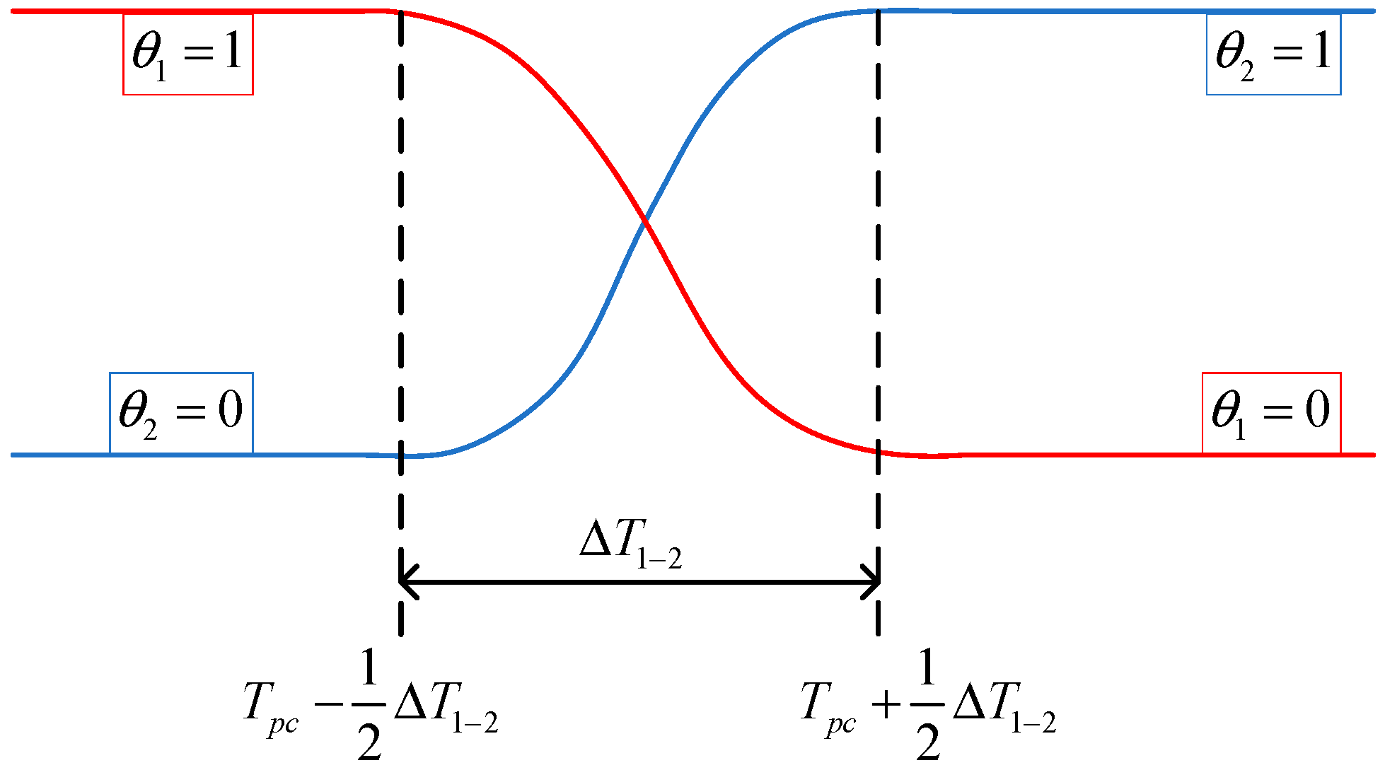
2.1. Heat Conduction Governing Equation

The calculation control equation of the heat transfer process in frozen soil still follows the differential heat conduction equation [18], which can be expressed as:
ρ C p T t + q ~ = Q
q ~ = k T
where T represents the temperature, k represents the thermal conductivity, ρ represents the density, C p represents the specific heat capacity, and Q represents the total heat source, here contains the phase transformation latent heat.
When a material undergoes a phase transition, take solid to liquid as an example, energy is added to the solid, and instead of creating a temperature rise, the energy alters the material’s molecular structure. Therefore, in the process of soil freezing, the phase change of water in the soil will slow down the development of the frozen soil curtain.
The equivalent heat capacity method is applied to calculate the latent heat of the phase transformation [19], and the following model is used to ensure the continuity of boundary conditions in the finite element calculation process, shown in Figure 1.
C p = θ 1 C p 2 + θ 2 C p 2 + Q 1 2 α m T
α m = 1 2 θ 2 θ 1 θ 2 + θ 1
In this equation, Δ T 1 2 represents the phase transition interval, T pc represents the transformation temperature, θ 1 and θ 2 represents the ratio of phase 1 and phase 2, and Q 1 2 represents the latent heat of phase change, and the proportional coefficient represents the phase change conversion.

2.2. Coupling Calculation Model of Shield Machine Heating and Freezing Cooling

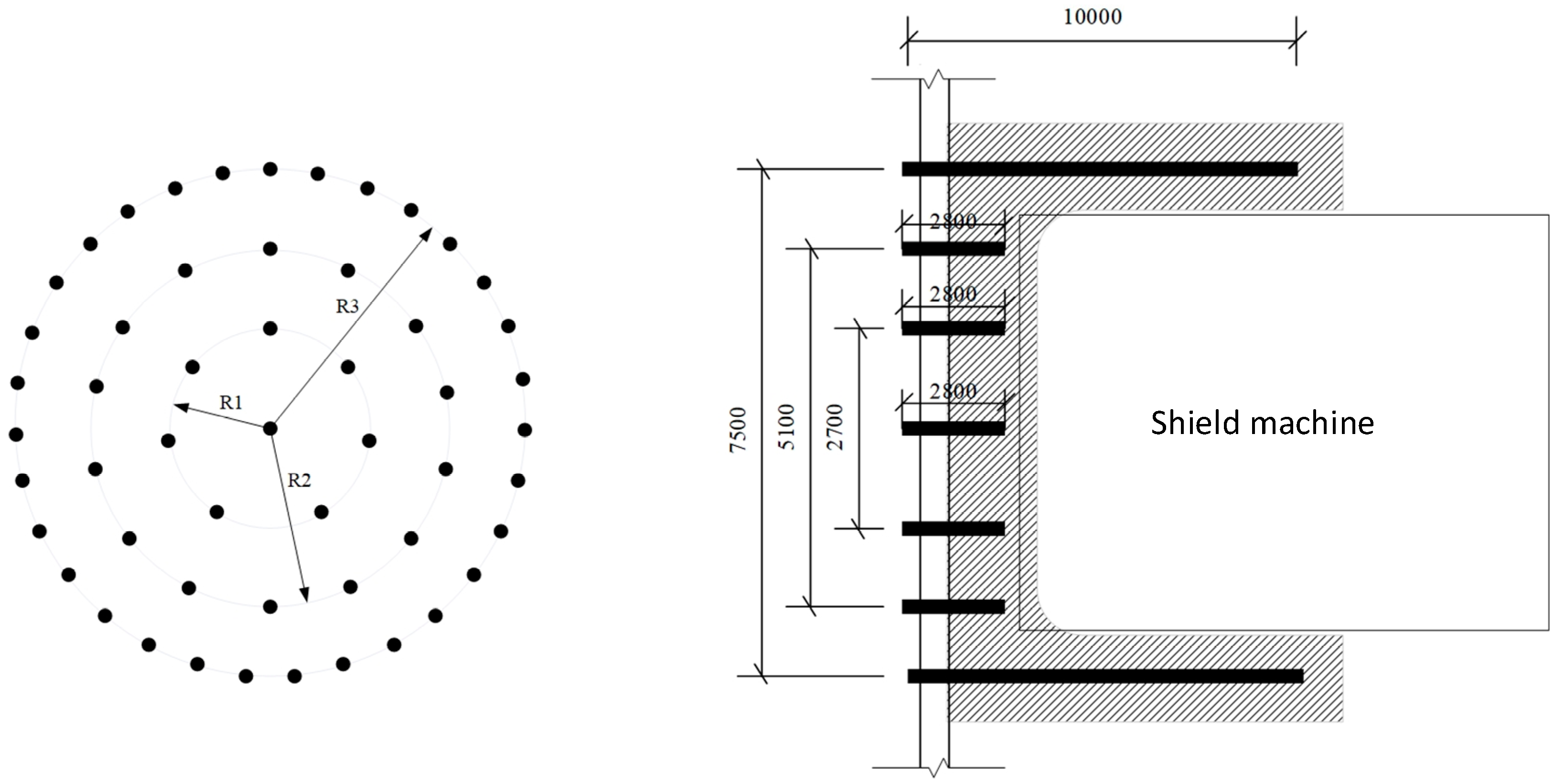
2.2.1. Layout Scheme of Freezing System

The coupling model of the shield tunneling breakthrough working shaft was established to reference the layout of freezing pipe proposed by Luo [20]. This model adopts a three-dimensional finite element simulation with a total of 435,242 solid elements. The construction is based on a Cartesian rectangular coordinate system. The tunnel excavation direction is along the y-axis direction, the soil depth direction is along the z-axis direction, and the horizontal direction perpendicular to the tunnel excavation direction is the x-axis direction.
The size of the frozen soil curtain is designed according to the size of the shield machine and the tunnel, the buried depth of the tunnel, the layout of the freezing pipe, and other factors in the actual project. The general diameter of the shield is 6.85 m, and the distance from the ground to the freezing pipe is 15 m, close to the tunnel depth. A total of 53 freezing pipes are arranged in three circles inside and outside the opening center. Among them, the outer ring layout has 31 freezing pipes with a ring radius R3 of 3.75 m, a freezing pipe spacing arc of 0.76 m, a freezing pipe length of 10 m; 14 freezing pipes are arranged in the middle ring with the ring radius R2 of 2.55 m, a freezing pipe spacing arc of 1.14 m, and a freezing pipe length of 2.8 m; 7 freezing pipes are arranged in the inner ring with the ring radius R1 of 1.35 m, a freezing pipe spacing of 1.21 m, and a freezing pipe length of 2.8 m; a freezing pipe with a length of 2.8 m was laid in the center of the shield. The layout scheme of freezing pipes is shown in Figure 2.

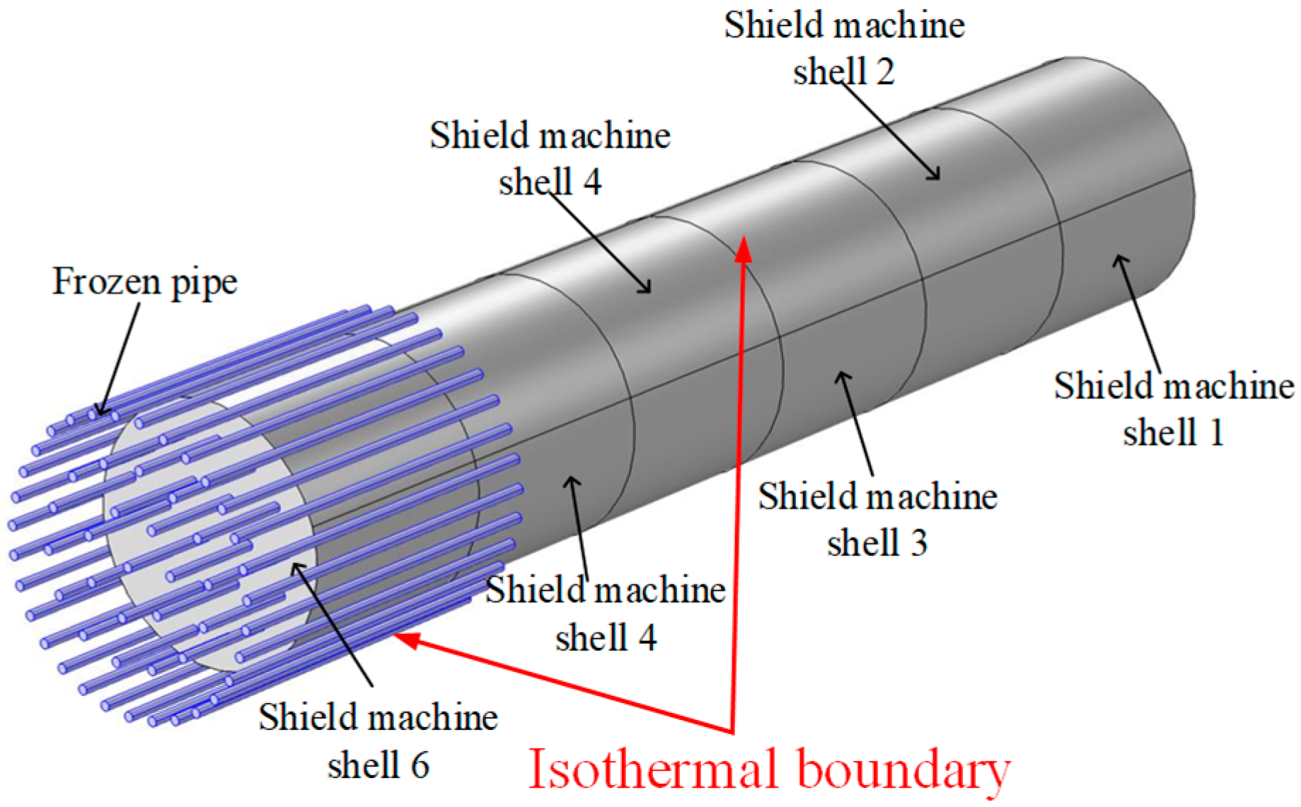
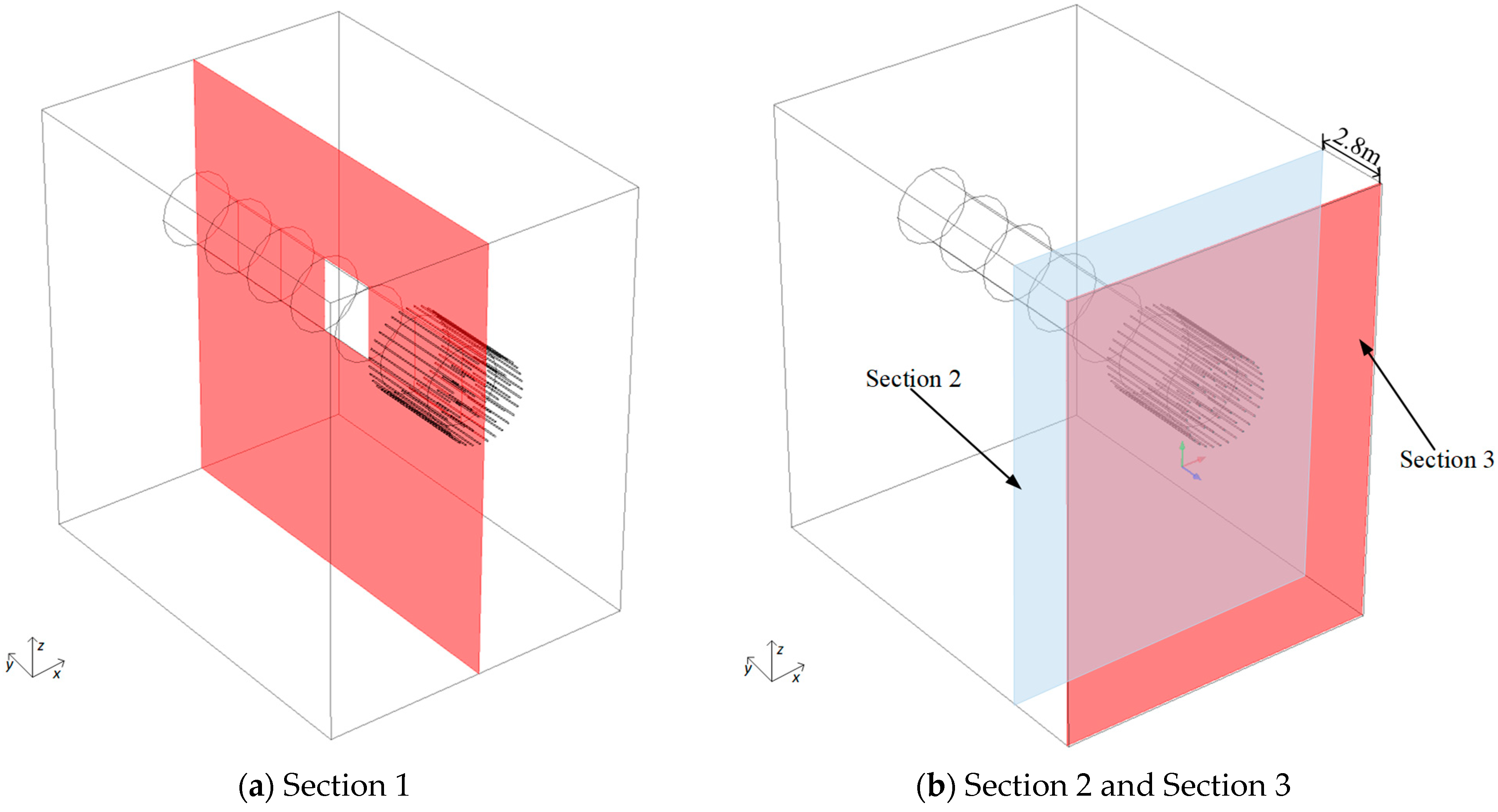
2.2.2. The Finite Element Model

Considering the above factors and to eliminate the boundary effect, the plane of the model face is 30 m × 40 m. Considering the dynamic jacking process of the shield, the shield jacking route is partitioned along the tunnel axis. According to the engineering experience, the shield machine can complete the assembly of approximately five rings of segments every day under normal conditions. Therefore, the model takes a length of 6 m for each five-ring segment as the tunneling progress. The length of the freezing pipe in the other inner ring is 2.8 m, so the geometric size of the soil is designed as horizontal width (X-axis direction) × longitudinal length (Y-axis direction) × vertical depth (Z-axis direction) = 30 m × 38.9 m × 40 m. After the trial calculation, the range of this model is much larger than that of the freezing affected area, which is more reasonable and eliminates the error caused by the asymmetry of the freezing pipe, as shown in Figure 3 and Figure 4.
The temperature boundary is used for the boundary condition of the freezing pipe cooling, and the calculation equation is shown with:
T = T 0
The side, lower, and rear parts of the soil are semi-infinite spaces. An adiabatic boundary is used, and the calculation equation is shown with:
q ~ = 0
The upper surface of the soil and the entrance of the shield are external air. The second boundary considering air thermal convection is used. The calculation equation is shown with:
q 0 = h ( T e x t T )
In this Equation (7), T e x t represents outside temperature, h represents the convection coefficient. Soil is used as a phase change material, and the phase change temperature is considered to be 0 °C.

2.2.3. Parameters of the Model

Refer to the research on the surface temperature of shield tunneling machines by Liu [21]. The temperature values of the model are shown in Table 1.
The thermophysical parameters of materials are shown in Table 2.

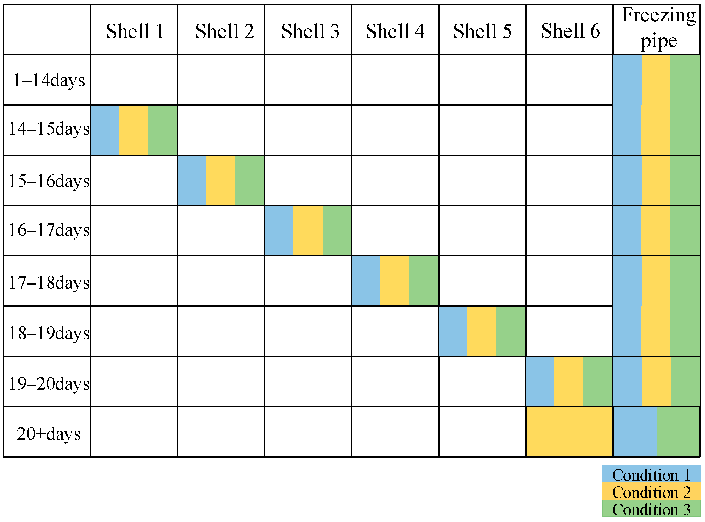
2.3. Simulated Working Conditions

The freezing scheme shows that the cooling brine circulation from the 1st day to the 10th day, the temperature is reduced by 2.8 °C per day; the active freezing period is from the 10th to the 35th days, and the temperature is stable at −28 °C. The maintenance freezing period is from the 35th to the 43rd days, and the temperature is −22 °C. When the active freezing period is completed, the frozen soil curtain reaches the design standard, the temperature boundary of the shield shell is activated in turn, and the excavated soil is converted into air.
The first model is based on the normal working condition without considering the heating effect of the shield machine, which can be used to verify the model. Then, the following three working conditions are proposed for the simulation analysis: the shield tunneling considering the heating effect of shield machine (Condition 1), the continuous rotation working condition of tunneling at the same position due to encountering hard rock formations (Condition 2), and the temporary shutdown condition of tunneling at the same position due to construction arrangements, equipment fault, or other reasons (Condition 3). The corresponding model boundary of each extreme working condition is shown in Figure 5.

3. Modelling Results

To study the development law of frozen soil area, three critical sections and seven critical reference lines were selected for data analysis.
Section 1 is the section yz located in the longitudinal symmetry plane of the shield machine and the tunnel, shown in Figure 6a. Section 2 is the section xz at the bottom of the cup-shaped freezing design, shown in Figure 6b. Section 3 is the section xz at the outermost part of the model with the distance of 2.8 m from Section 2, shown in Figure 6b.
To quantify the accurate temperature change of the frozen soil curtain and determine the thickness of the frozen soil at the bottom of the cup-shaped freezing design, seven temperature reference lines are added based on the selected critical sections, and the accurate distribution of the frozen soil curtain is determined by obtaining the distribution law of the temperature extension reference line. To study whether the bottom of the cup-shaped freezing design is frozen to meet the requirements, reference line 1 and reference line 2 are selected in Section 3. At the same time, to study the specific bottom thickness of the cup-shaped freezing design, two weak points at the gap of the freezing pipe are selected as reference line 3 and reference line 4 in Section 1. For the thickness of the frozen soil, the design requirement should reach 1.2 m. Three x-direction straight lines crossing the center of the frozen soil curtain at 4 m, 6 m, and 8 m from the bottom of the cup-shaped freezing design are selected as the reference lines, which are reference line 5, reference line 6, and reference line 7, respectively. The position of the reference lines are shown in Figure 7.

3.1. Model Verification

Firstly, the model is verified by the development law of the frozen soil curtain without considering the thermal influence of the shield machine. The isotherm line of 0 °C and temperature cloud map of Section 1 of the working shaft breakthrough freezing reinforcement from the 5th to the 30th days are shown in Figure 8. As shown in Figure 8, the frozen area gradually forms a cup-shaped body on the 10th day, and the soil temperature is controlled below −10 °C within the length of the inner ring freezing pipe in the middle circle, forming a stable frozen soil curtain. The design requirements can be met on the 14th day.
The temperature cloud diagram and the isotherm line of 0 °C at the bottom of the cup-shaped freezing design (Section 2) are shown in Figure 9. It can be seen from the figure that when 0 °C is taken as the freezing temperature of the soil, the freezing area achieves closure on the 9th day, forming a complete bottom area of cup-shaped freezing.
The result is compared to the numerical simulation result of the cup-shaped freezing design of tunneling breakthrough working shaft by Luo [20] to verify the model, which is based on the freezing reinforcement project of the shield launching at the west end of Yixianqiao Station of Nanjing Metro Line 2.

3.2. The Shield Tunneling Considering Heating Effect of Shield Machine

According to the preliminary simulation results of the above freezing scheme, each part of the frozen soil curtain fully reached the design thickness on the 14th day, so shield jacking is carried out from the 14th day. Taking the aforementioned reference line and section as the characteristic line and plane, the development of a frozen soil curtain, considering the thermal disturbance of the shield machine, is observed and analyzed.
Figure 10 is the temperature cloud of Section 1. It can be seen from Figure 10 that the frozen soil curtain melts as the shield machine continues to tunnel. The bottom and side of the cup-shaped frozen soil curtain melted from the 18th day, the side of the cup-shaped frozen soil curtain melted more obviously by approximately 19.5 days, and the outer ring inside the cup-shaped freezing pipes arrangement was part of the basic melt.
To more specifically analyze the melting situation of the frozen soil curtain at the bottom part of the cup-shaped freezing curtain and judge whether the thickness of the curtain after melting can maintain the requirements of shield construction, the temperature distribution curve on the aforementioned characteristic line is taken for analysis.
The temperature distribution of the characteristic lines (line 3, line 4) at the bottom of the cup-shaped frozen soil curtain is shown in Figure 11. The bottom thickness of line 3 and line 4, which were 3.09 m and 3.23 m, still meet the design requirements on the 19th day. The bottom thickness of the cup-shaped frozen soil curtain was 2.65 m and 2.69 m, which does not meet the design requirements of 2.8 m after 19.5 days.
The temperature distribution curve of the cup-shaped frozen soil curtain is shown in Figure 12. After 19.5 days, the thickest part of the frozen soil curtain is 0.9 m, and the thinnest part is only 0.6 m, which is far less than the design requirement of 1.2 m.
It can be seen from the diagram that as the top of the shield machine dissipates heat, the cooling capacity of the original freezing scheme is not enough to offset the heat generated by the continuous shield tunneling, the frozen soil melts, and the bottom and side part of the cup-shaped frozen soil curtain cannot maintain the design thickness, which is a high risk. It is necessary to take some construction measures to ensure the thickness of the frozen soil curtain.

3.3. The Continuous Rotation Working Condition

In the actual project, the tunneling of the shield machine is not a completely smooth process. In the process of shield tunneling, hard gravel may be encountered, which makes it difficult for the shield machine to tunnel at a normal speed, which causes it to continue to dissipate heat in the same place. Therefore, this study also discusses this condition. In the model, the tunneling duration of the shield machine in a certain partition is extended to simulate the in-situ cutting of the soil at a certain position for a long time.
Figure 13 shows the thickness variation curve of the two reference lines at the bottom of the frozen soil curtain during the shielding process. From the diagram, it can be found that when the shield first enters the cup-shaped frozen body area on the 19th–20th day, the bottom thickness of the cup-shaped frozen curtain decreases the fastest. With the increase of residence time, the heat of the shield machine and the cooling capacity of the freezing system gradually reach equilibrium. Finally, on the 28th day, the thickness on line 3 reduced to 2.46 m and the thickness on line 4 reduced to 2.52 m.
Figure 14 shows the thickness of the frozen soil curtain in different line. It is similar to the rule at the bottom, the freezing curtain melts rapidly as the shield machine enters on the 19th–20th day. The thickness of frozen soil curtain also reached a relatively stable value on approximately the 26th day. The thickness of reference line 5 is 0.79 m. The thickness of reference line 6 is 0.80 m, and the thickness of reference line 7 is 0.74 m.
It can be seen that under the influence of the heat of the shield machine, the frozen curtain cannot maintain the 1.2 m thickness required by the design. However, the freezing curtain will not be completely melted due to the heat generated by the shield machine. It still has a certain thickness, which can play an important part in water shut-off and reinforcement.

3.4. The Temporary Shutdown Condition

In actual engineering, due to the instability of the stratum, the shielding process is often disturbed by various factors, resulting in shutdown adjustment. In the case of a breakthrough working shaft by AGF, the shield machine stays in the designated fixed position for a long time, which leads to the lower temperature of the soil around the cutter head and makes it difficult to move forward during the secondary start-up, and can even make the cutter head freeze. This study mainly analyzes the most extreme condition, that is, the relationship between the time the shield machine stays in and the freezing risk.
According to the study of the shear properties of frozen clay by Sun [22], the shear properties of frozen soil are mainly related to temperature and corresponding force, thus the specific relationship is shown in Equation (8).
τ = ( 0.021 T + 0.637 ) σ + 16.05 e 0.09 T
In which, T is the soil temperature, σ is vertical stress, and τ is shearing stress.
In this model, the main resistance of the shield machine shell is from the shearing stress of the surrounding soil. Taking a point above the shield machine as an example, the plane stress state is shown in Figure 15. The vertical stress is mainly provided by the pressure of the surrounding soil, that is, the vertical stress comes from the self-weight stress and lateral earth pressure of the soil.
According to Equation (8), a critical temperature value can be obtained. In the study, it is considered that when the boundary temperature of the contact surface between the shield machine and the frozen soil in the model drops to this temperature, the corresponding time is the time when the shield machine is allowed to stop. Beyond this time, the shield machine will be unable to keep tunneling due to the freezing conditions.
Taking a meter of the unit strip for analysis, the three-dimensional problem is simplified to a two-dimensional problem, and the sum of the vertical stress perpendicular to the tunnel can be calculated. The calculation diagram is shown in Figure 16.
The total pressure can be calculated as follows.
σ V = 10.65 * 18.424 * 6.75 = 1324.46   kN / m
σ A = 0.43 * 18.424 * 6.75 * 6.75 = 360.96   kN / m
σ H = ( 107.92 + 176.32 ) * 6.75 / 2 = 959.31   kN / m
σ = ( 1324.46 + 360.96 ) * 2 + 959.31 * 2 = 5325.46   kN / m
where σ V represents vertical earth pressure, σ A represents soil pressure at arch back, σ H represents horizontal earth pressure, and σ represents the total pressure.
According to Deng’s research for an earth pressure shield machine with a general diameter of 6 m [23], the empirical formula of the shield total thrust is shown in Equation (13).
F = 1 4 π D 1 2 P j
In this expression, D 1 represents the excavation diameter of the shield machine. P j represents the average thrust per unit of excavation face. In this model, D 1 is taken as 6.75 m, and P j is taken as 1300 kN.
Based on the temperature-dependent characteristics of the freezing force at the contact surface between the frozen soil and shield machine shell, the resistance of the tunneling force and the freezing force of the shield machine can be calculated. When the shear strength of the contact surface between the frozen soil and shield machine shell is stronger than the total thrust of the shield machine, the shield machine will not be able to tunnel ahead. The critical temperature is −12 °C, solved by Equation (8).
The research goal of this study is to analyze the temperature change of the surrounding soil and the possible freezing risk when the shield machine is stopped due to special circumstances when the shield machine reaches the frozen soil curtain area. Based on the basic shield tunneling simulation, the model cancels the heat generation of the shield machine after the shield machine reaches the frozen area to realize the transient simulation of the temperature change after the shield machine is shut down. When the temperature at the boundary is lower than the critical temperature, there is a risk that the shield machine cannot continue tunneling forward due to excessive freezing. The freezing temperature development cloud map of Section 1, after the arrival of the shield for six days, is shown in Figure 17.
It can be seen from the cloud map that the freezing area develops from the freezing pipe area to the surrounding area with time. The freezing area in the upper part of the section develops faster than the lower part, due to the incomplete symmetrical arrangement of the freezing pipe. On the fourth day, the critical freezing temperature boundary of −12 °C has roughly covered all the contact surfaces between the shield machine and frozen soil, which leads to a higher risk that it cannot continue tunneling forward due to excessive freezing.

4. Conclusions

In this paper, a coupling model of the shield tunneling breakthrough working shaft by AGF considering the phase change of latent heat is established and verified, and several extreme working conditions are analyzed.
(1)
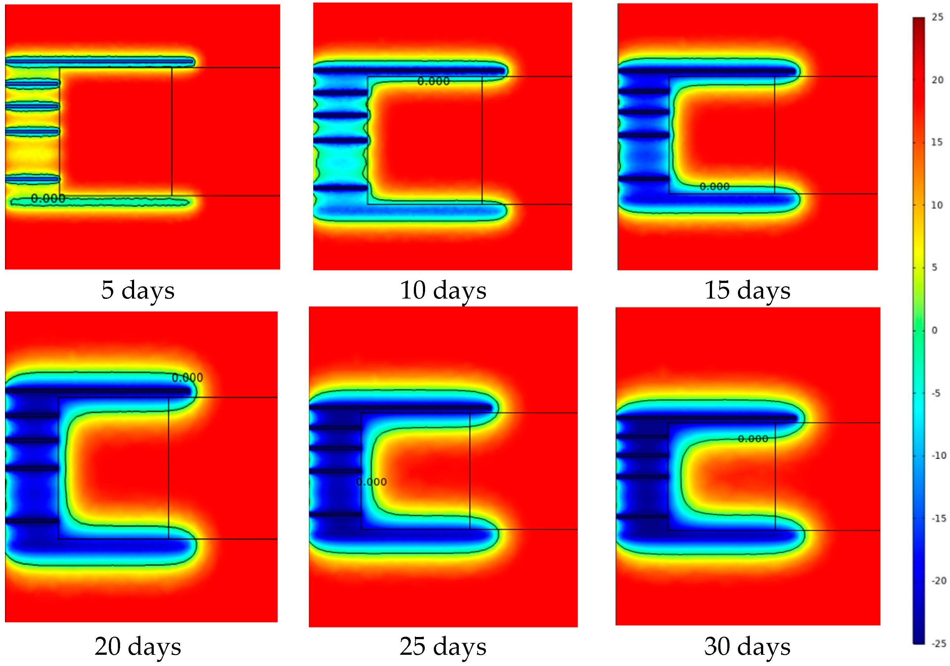
The heat generated by the tunneling of the shield machine will cause a certain melting of the frozen soil curtain that originally met the design requirements. After melting, the thickness of the frozen soil curtain cannot reach the initial design, but it is still within the safe range and can meet the tunneling requirements. It is recommended to add a switchable enhancing freezing tube arranged in the outer ring to deal with the melting in extreme conditions.
(2)
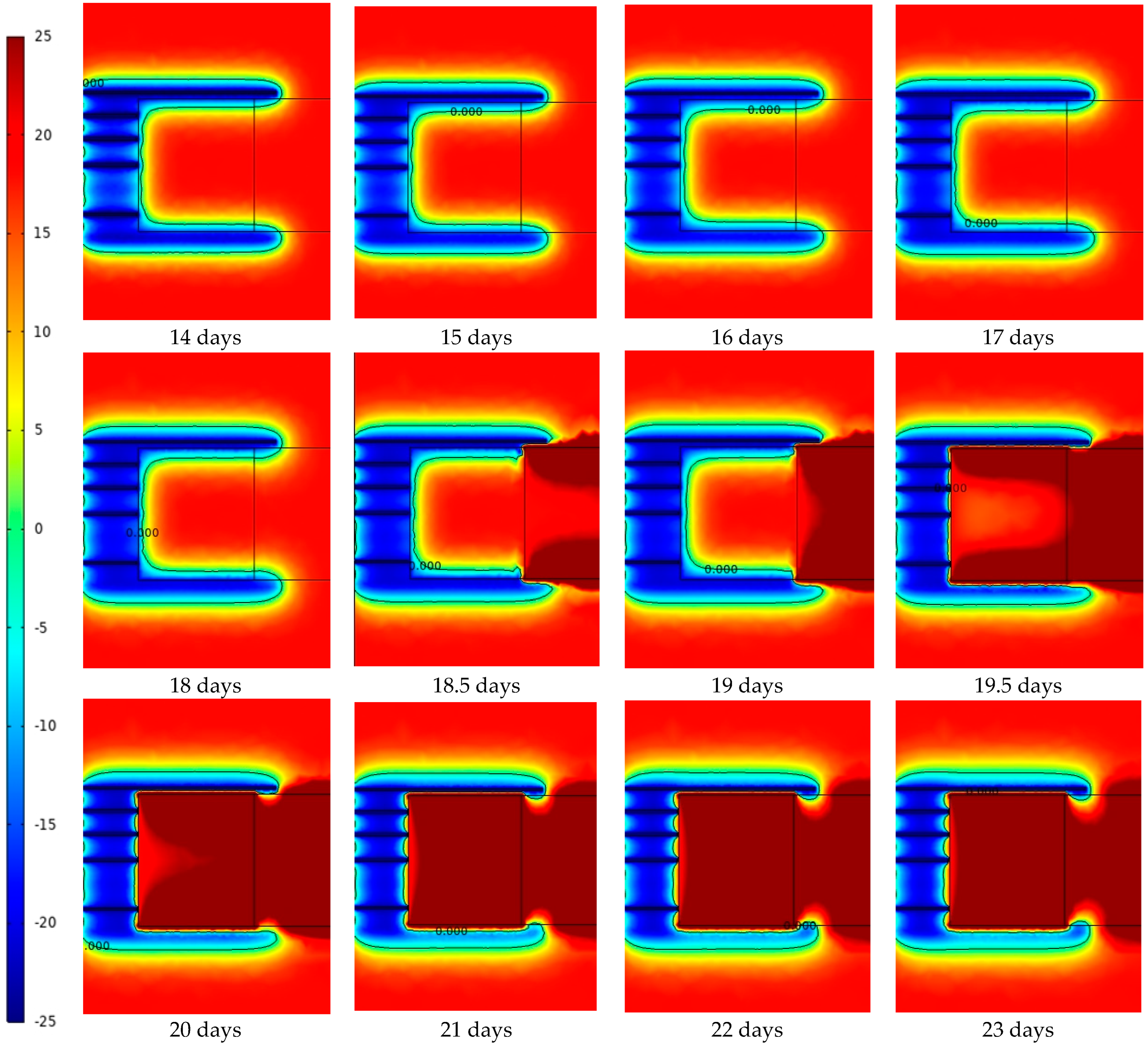
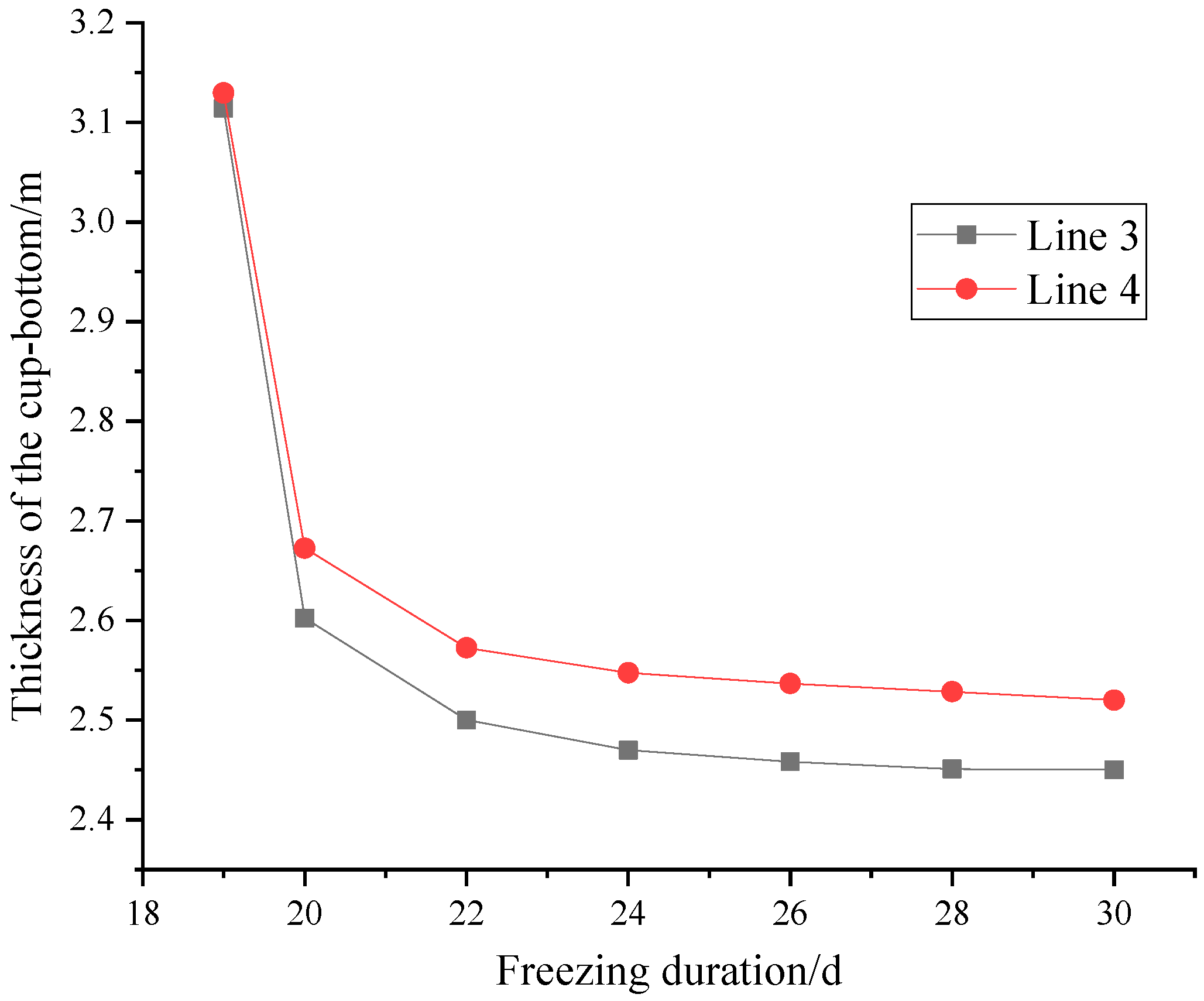
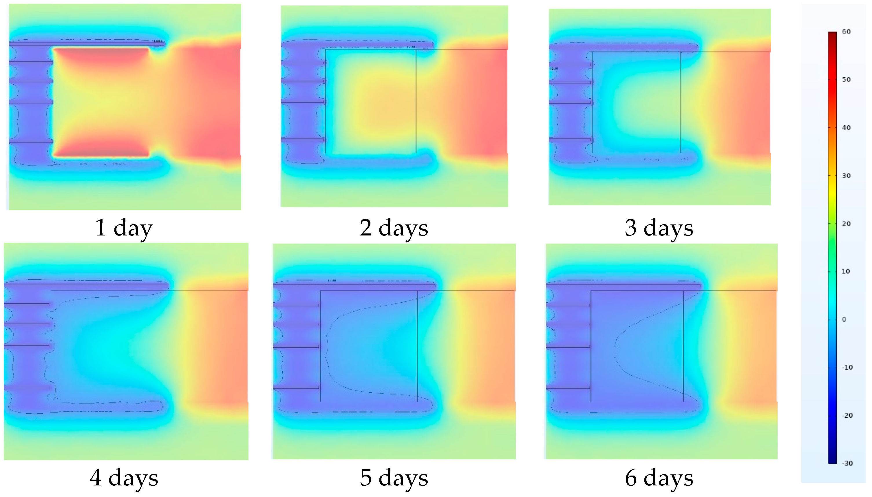
When the shield tunneling encounters harsh geological conditions, such as hard rock strata, the heat emitted by the in-situ operation of the shield machine will continue to cause the melting of the frozen soil curtain under the condition that the cutter head needs to be cut at the same position for a long time. In the early 6 day stay of the shield machine, the bottom and sides of the cup-shaped frozen soil curtain are partially melted. Then, the thickness is reduced to a relatively stable value, of approximately 0.8 m, and the bottom part continues to melt at a small rate. If proper measures are not taken to enhance the freezing effect, it will lead to water flow channels, leading to engineering disasters.
(3)
In a temporary shutdown working condition, when the contact surface temperature between the shield machine shell and the frozen soil drops to −12 °C, after almost 4 days of shutdown, the shield machine may not keep tunneling forward due to the freezing effect.

Author Contributions

Conceptualization, S.D. and F.Z.; methodology, Y.H.; software, Y.H. and M.Y.; validation, R.Z., Z.W. and H.L.; formal analysis, M.Y.; investigation, R.Z.; resources, Z.W.; writing—original draft preparation, M.Y.; writing—review and editing, Y.H. and S.D.; supervision, S.D. and F.Z.; project administration, S.D.; funding acquisition, F.Z. All authors have read and agreed to the published version of the manuscript.

Funding

This research was funded by the National Natural Science Foundation of China (NSFC) (Grant No. 52008208 and 51778287), Natural Science Foundation of Jiangsu Province (Grant No. BK20200707), Key Laboratory of Soft Soils and Geoenvironmental Engineering (Zhejiang University), Ministry of Education (Grant No. 2020P04), Opening Project of Tunnel and Underground Engineering Research Center of Jiangsu Province (Grant No. 2021SDJJ06), Postgraduate Research & Practice Innovation Program of Jiangsu Province (SJCX22_0466).

Institutional Review Board Statement

Not applicable.

Informed Consent Statement

Not applicable.

Data Availability Statement

Not applicable.

Acknowledgments

The funding above is gratefully acknowledged.

Conflicts of Interest

The authors declare no conflict of interest.

References

  1. He, S.Y.; Lai, J.X.; Wang, L.X.; Wang, K. A literature review on properties and applications of grouts for shield tunnel. Constr. Build. Mater. 2019, 239, 2–17. [Google Scholar] [CrossRef]
  2. Hong, K.R. Development and prospects of tunnels and underground works in China in recent two years. Tunn. Constr. 2017, 2, 14–25. [Google Scholar]
  3. Li, J.; Li, J.K.; Cai, Y.C.; Wu, D.Y.; Guo, C.X.; Zhao, W.C.; Tang, K.J.; Liu, Y.H. Application of Artificial Freezing Method in Deformation Control of Subway Tunnel. Adv. Mater. Sci. Eng. 2022, 2022, 3251318. [Google Scholar] [CrossRef]
  4. Tang, S.H.; Zhang, X.P.; Liu, H.; Zhang, L.L.; Zhang, J.; Chen, P.; Bai, K.; Wu, K. Engineering difficulties and key technologies for underwater shield tunnel in complex ground. J. Eng. Geol. 2021, 5, 1477–1487. [Google Scholar]
  5. Fu, Y.; Hu, J.; Wu, Y.W. Finite element study on temperature field of subway connection aisle construction via artificial ground freezing method. Cold Reg. Sci. Technol. 2021, 189, 103327. [Google Scholar] [CrossRef]
  6. Qi, Y.; Zhang, J.X.; Yang, H.; Song, Y.W. Application of Artificial Ground Freezing Technology in Modern Urban Underground Engineering. Adv. Mater. Sci. Eng. 2020, 2020, 1619721. [Google Scholar] [CrossRef]
  7. Zhan, Z.X.; Cui, Z.D.; Yang, P.; Zhang, T. In situ monitoring of temperature and deformation fields of a tunnel cross passage in Changzhou Metro constructed by AGF. Arab. J. Geosci. 2020, 2020, 310. [Google Scholar] [CrossRef]
  8. Hu, X.D.; Fang, T.; Chen, J.; Ren, H.; Guo, W. A large-scale physical model test on frozen status in freeze-sealing pipe roof method for tunnel construction. Tunn. Undergr. Space Technol. 2018, 72, 55–63. [Google Scholar] [CrossRef]
  9. Alzoubi, M.A.; Aurelien, N.R.; Agus, P.S. Conjugate heat transfer in artificial ground freezing using enthalpy-porosity method: Experiments and model validation. Int. J. Heat Mass Transf. 2018, 126, 740–752. [Google Scholar] [CrossRef]
  10. Ahmad, Z.; Aurelien, N.R.; Mahmoud, A.A.; Agus, P.S. Thermal and hydraulic analysis of selective artificial ground freezing using air insulation: Experiment and modeling. Comput. Geotech. 2020, 120, 103416. [Google Scholar]
  11. Li, W.; Zhang, C.P.; Tan, Z.B.; Ma, M.S. Effect of the seepage flow on the face stability of a shield tunnel. Tunn. Undergr. Space Technol. 2021, 112, 103900. [Google Scholar] [CrossRef]
  12. Alessandro, M.; Gennaro, N.; Filippo, C.; Pasquale, M.; Nicola, M. Modeling Artificial Ground Freezing for Construction of Two Tunnels of a Metro Station in Napoli (Italy). Energies 2020, 13, 1272. [Google Scholar]
  13. Fu, Y.; Hu, J.; Liu, J.; Hu, S.B.; Yuan, Y.H.; Zeng, H. Finite Element Analysis of Natural Thawing Heat Transfer of Artificial Frozen Soil in Shield-Driven Tunnelling. Adv. Civ. Eng. 2020, 2020, 2769064. [Google Scholar] [CrossRef]
  14. Alzoubi, M.A.; Xu, M.H.; Hassani, F.P.; Poncet, S.; Sasmito, A.P. Artificial ground freezing: A review of thermal and hydraulic aspects. Tunn. Undergr. Space Technol. 2020, 104, 103534. [Google Scholar] [CrossRef]
  15. Ou, C.Y.; Kao, C.C.; Chen, C.L. Performance and Analysis of Artificial Ground Freezing in the Shield Tunneling. J. GeoEngineering 2009, 4, 29–40. [Google Scholar]
  16. Hu, J.; Liu, Y.; Li, Y.P.; Kai, Y. Artificial ground freezing in tunnelling through aquifer soil layers: A case study in Nanjing Metro Line 2. KSCE J. Civ. Eng. 2018, 22, 4136–4142. [Google Scholar] [CrossRef]
  17. Hu, J.; Liu, W.B.; Pan, Y.T.; Zeng, H. Site Measurement and Study of Vertical Freezing Wall Temperatures of a Large-Diameter Shield Tunnel. Adv. Civ. Eng. 2019, 2019, 8231458. [Google Scholar] [CrossRef]
  18. Yang, S.M.; Tao, W.Q. Heat Transfer, 4th ed.; Higher Education Press: Beijing, China, 2006; pp. 112–138. [Google Scholar]
  19. Pan, A.G.; Wang, J.B.; Zhang, X.J. Numerical Analysis of Phase-Change Heat Transfer Characteristics Using Effective Heat Capacity Method and Enthalpy Method. Comput. Simul. 2014, 31, 315–319. [Google Scholar]
  20. Luo, T.; Hu, J.; Wei, H. Numerical Optimization Analysis of Temperature Field with Shield Tunnelling Cup-shaped Freezing Wall. Forest Eng. 2017, 33, 83–88. [Google Scholar]
  21. Liu, D.Y.; Zhang, N.C. Calculation and Analysis of Heat Balance of Boring of Shield TBMs. Tunn. Constr. 2006, 26, 82–86. [Google Scholar]
  22. Sun, H.C.; Ma, A.Q.; Yang, P.; Zhang, F. Comparative Analysis of Monotonic Shearing Test and Numerical Simulation for Interface Layer of Frozen Soil. For. Eng. 2022, 38, 133–139. [Google Scholar]
  23. Deng, L.J.; Liu, C.G.; Dang, J.F. Research on method of calculating torque of cutter head of shield machine and thrust of shield. Min. Process. Equip. 2010, 38, 13–16. [Google Scholar]
Figure 1. Schematic diagram of latent heat of phase transformation.
Applsci 13 03651 g001
Figure 2. Layout diagram of freezing pipes (unit: mm).
Applsci 13 03651 g002
Figure 3. Model diagram.
Applsci 13 03651 g003
Figure 4. Shield freezing system model.
Applsci 13 03651 g004
Figure 5. Relationship between model boundary and working conditions.
Applsci 13 03651 g005
Figure 6. Location of critical sections.
Applsci 13 03651 g006
Figure 7. Location of critical numerical reference lines.
Applsci 13 03651 g007
Figure 8. Temperature cloud map in Section 1.
Applsci 13 03651 g008
Figure 9. Temperature cloud map in Section 2.
Applsci 13 03651 g009
Figure 10. Temperature cloud map in Section 1.
Applsci 13 03651 g010
Figure 11. Temperature distribution curve at the bottom of cup-shaped frozen soil curtain.
Applsci 13 03651 g011aApplsci 13 03651 g011b
Figure 12. Temperature distribution curve of the cup-shaped frozen soil curtain.
Applsci 13 03651 g012
Figure 13. The bottom thickness of the cup-shaped frozen curtain.
Applsci 13 03651 g013
Figure 14. Thickness of the frozen curtain in different line.
Applsci 13 03651 g014
Figure 15. Plane stress diagram of soil element.
Applsci 13 03651 g015
Figure 16. Diagram of the calculation section.
Applsci 13 03651 g016
Figure 17. Temperature cloud map and isotherm of −12 °C on Section 1.
Applsci 13 03651 g017
Table 1. The temperature values of the model.
PositionTemperature/°C
Ambient temperature20
Initial soil temperature20
Shield cutterhead20
Shield shell60
Freezing pipesAccording to simulated conditions
Table 2. The thermophysical parameters of materials.
Frozen SoilUnfrozen SoilAir
Thermal conductivity/(W/(m∙K))1.791.180.023
Specific heat capacity/(J/(kg∙K))161015301003
Density/(kg/m3)188018801.29
Disclaimer/Publisher’s Note: The statements, opinions and data contained in all publications are solely those of the individual author(s) and contributor(s) and not of MDPI and/or the editor(s). MDPI and/or the editor(s) disclaim responsibility for any injury to people or property resulting from any ideas, methods, instructions or products referred to in the content.

