In this section, the methodology for the selection of the study case is described. The system operating conditions are defined to obtain the minimum capacitance equation. Likewise, the definition and mathematical development of the equation are presented.
2.1. Case Study Selection
For the selection of the case study, an evaluation of the behavior of the energy flow in the system under different operating profiles of the electric vehicle is performed. The purpose of this is to carry out a comparison between the points with the highest energy return, to subsequently select the operating profile that represents the critical point with the highest energy stored by the decoupling system, which will be used for the development of the mathematical equation proposed in this article. The methodology used for the selection of the case study is listed below:
The analysis is delimited to the motor operation mode of the electric machine.
The operation profile to be analyzed (torque variation or speed variation at constant load) is selected.
The analysis of the power flow behavior in the selected profile is carried out, starting from the inverter current.
The point with the highest energy return in the working profile is identified.
The results of the previous point are obtained in both operation profiles.
A comparison is made of the points of highest energy return obtained in both work profiles (torque variation or speed variation at constant load).
The critical case with the highest level of energy return obtained from the previous step is selected.
Mathematical development is performed considering the selected critical case.
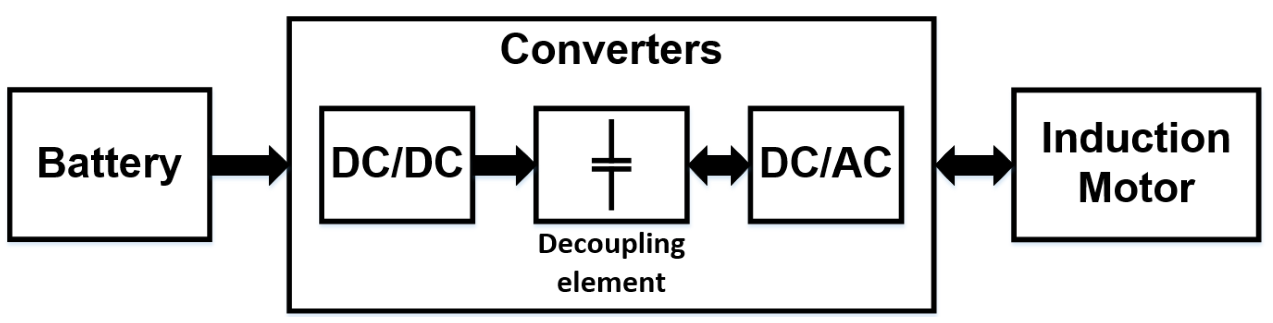
The mathematical development of the capacitance required by the decoupling system, using the critical point resulting from the abovementioned comparison, guarantees the correct operation of the system in less demanding work scenarios since it ensures that the calculated capacitor can operate in the case of a higher energy return. For the analysis of the operation profiles of the electric vehicle, a three-phase induction motor is used as load, whose specifications are shown in
Table 1, for accurate and consistent results with the application.
2.1.1. Torque Variation
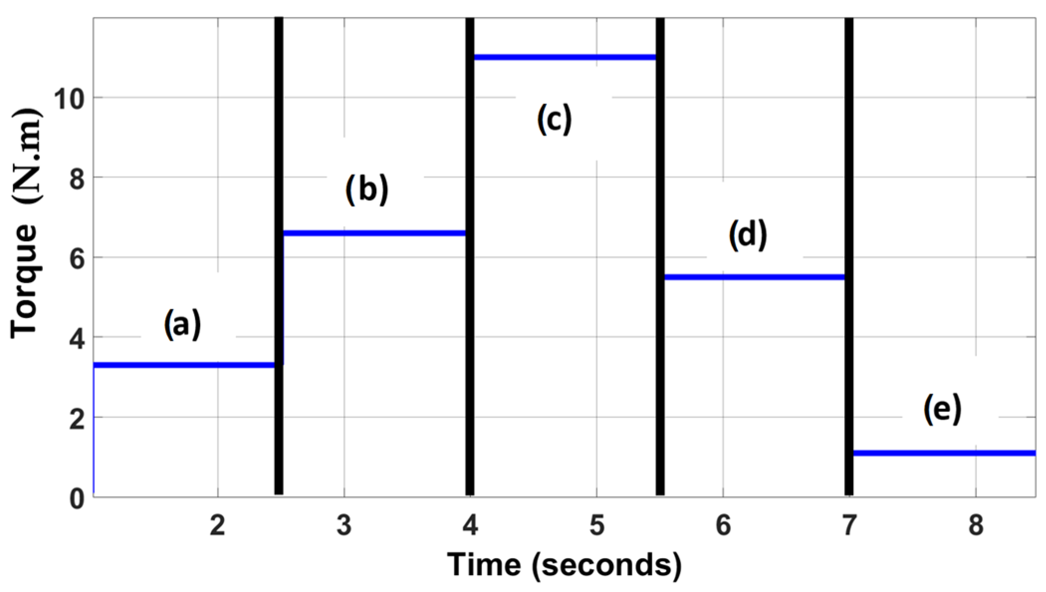
In this first operation profile, different slopes in the operation of the electric vehicle are emulated since these situations require different motor powers. For this purpose, a load variation technique is used to simulate the variation of the conditions of use of the electric vehicle.
For the analysis, different levels of torque variation are used to evaluate the power behavior of the system. These levels range from the nominal torque of the motor up to 10% of the motor (
Figure 3) and are essential to simulate high and low power demand situations in the vehicle applications.
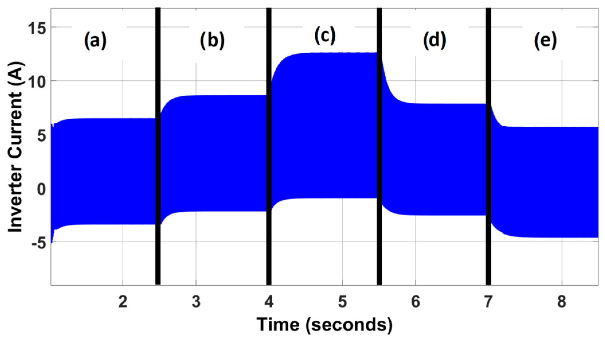
Figure 4 shows the inverter current (
iinv) at different intervals of the electric vehicle operation. It can be observed that there are intervals in which there is an energy return, which means that the current is negative. Emphasizing that the purpose of the variations presented is to observe the interval in which the greatest amount of energy is returned to the source.
The previous figure is important because it allows observation of the direction and magnitude of the electric current flowing through the inverter, which provides information about the energy behavior of the system. With the data provided in
Figure 3 and
Figure 4, it is emphasized that for this work scenario, the highest level of current return to the capacitor is presented at the moment of varying the torque from 50% to 10% of the nominal load.
2.1.2. Speed Variation at Constant Load
In this operation profile, the speed variation at a constant load is performed, which consists of modifying the speed of the electric motor while maintaining a constant load. This is done to observe the behavior of the energy under frequency and voltage variations.
To perform this operation profile, different voltage and frequency levels are applied to the electric motor, trying to maintain a constant load. In this way, the behavior and performance of the motor under different operating conditions can be evaluated.
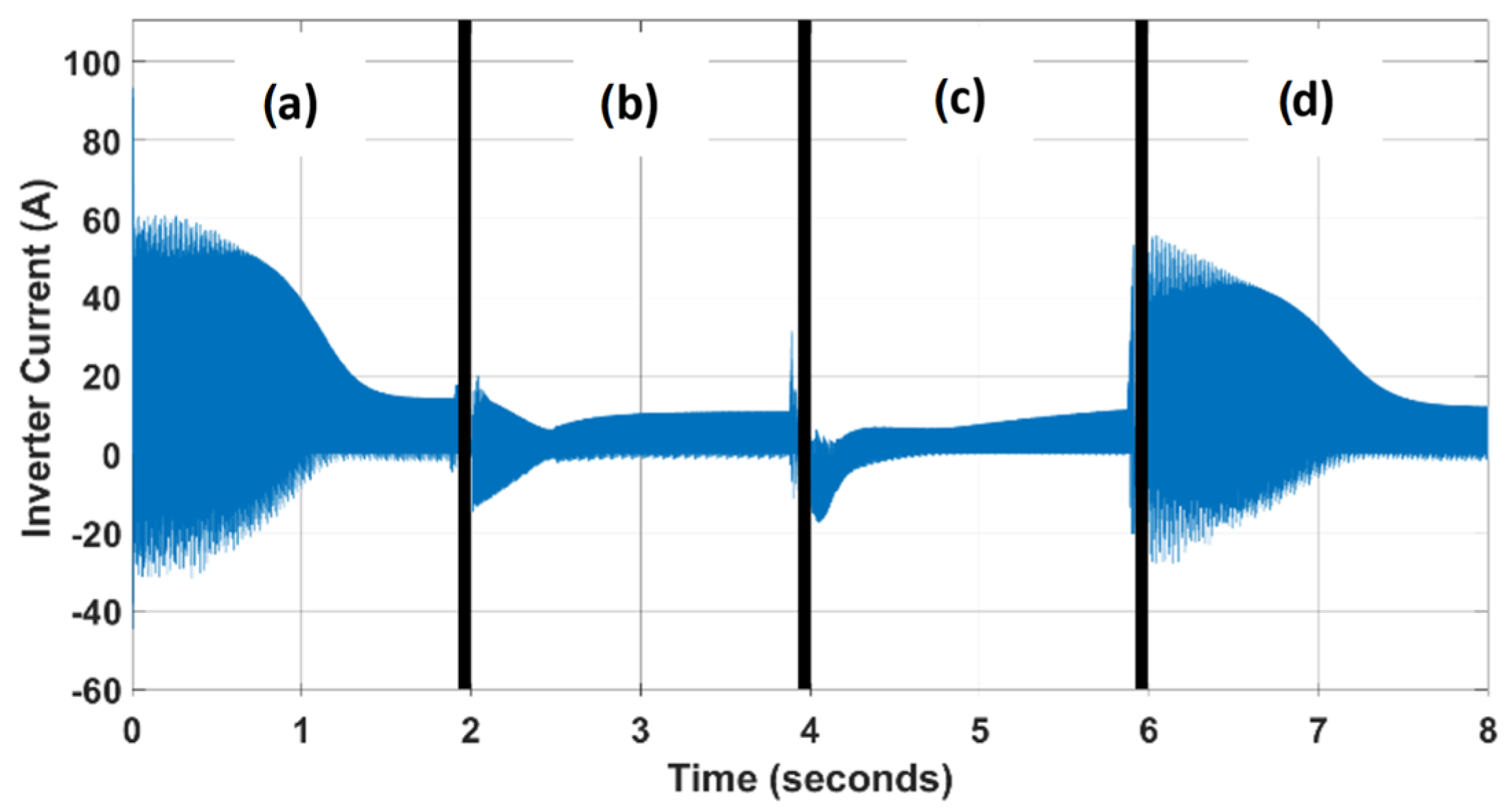
Figure 5 shows the inverter current obtained at different test speeds at constant load, which allows observation of the variation of the current as a function of the speed of the electric motor.
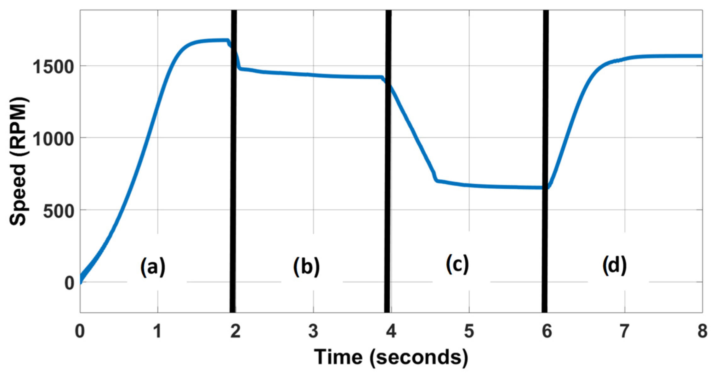
To perform the speed variation at constant load, previously defined speed variation steps are used. These steps are shown in
Figure 6 and represent the different frequency and voltage levels applied to the electric motor used as load.
Considering the information shown in
Figure 5 and
Figure 6, it can be observed that in this operating profile, the highest current return from the inverter to the decoupling capacitor occurs when varying from the idle state to the rated speed. Realizing a comparison between the critical point obtained in the first scenario (torque variation) and the critical point obtained in this second operation profile, the critical point that occurs when the speed of the electric motor is varied from the idle state to reach 100% of the nominal speed in the shortest possible time, under the conditions established in the work, is selected as a case study, from which the mathematical equation of minimum capacitance developed in this article is based.
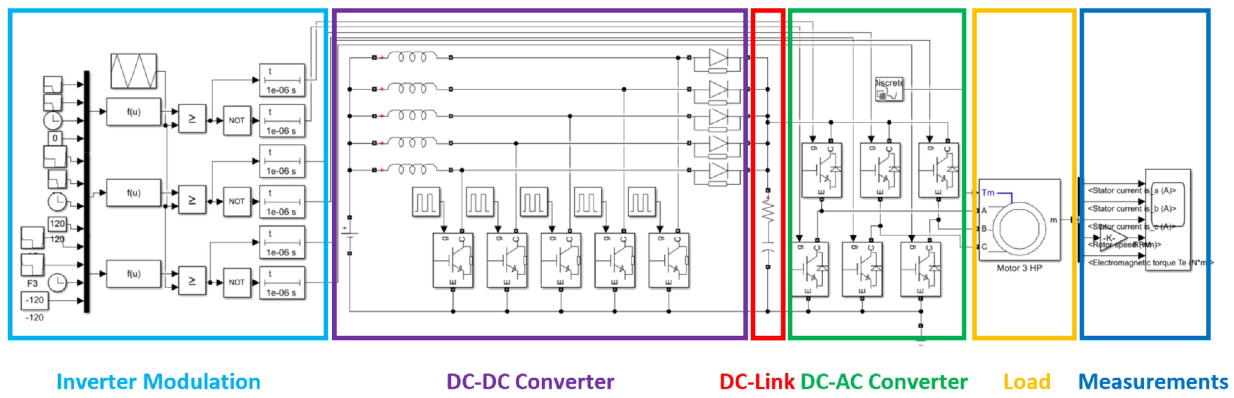
To develop the required minimum capacitance equation, it is necessary to identify the critical intervals of the returned power, in the previously selected case study. Subsequently, simulations were performed with the specifications shown in
Table 2, to obtain the signal patterns of the inverter and the DC-link in these critical intervals.
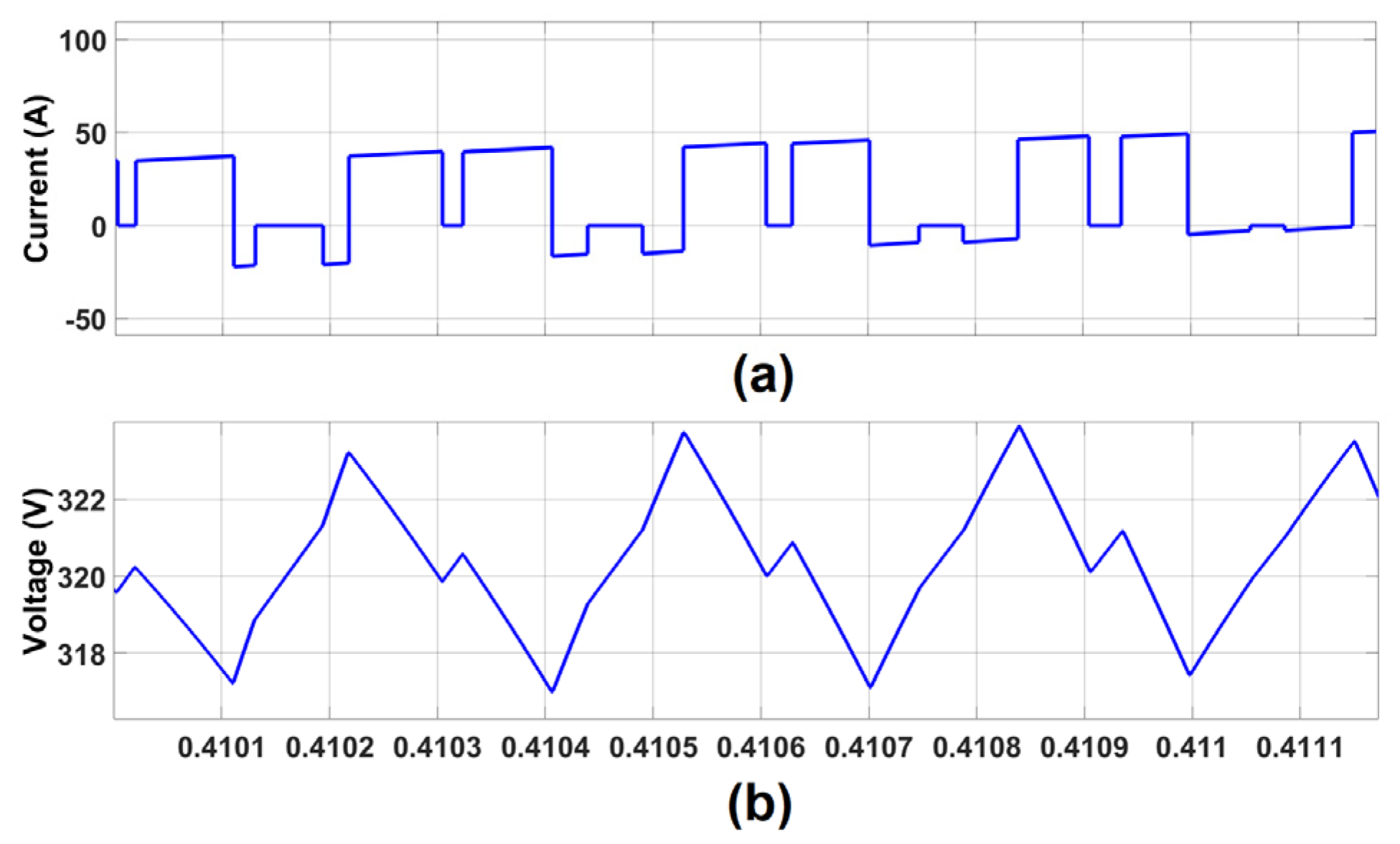
The waveform pattern of the inverter current and capacitor voltage (VC) waveforms are shown in
Figure 7, zooming in on
Figure 8.
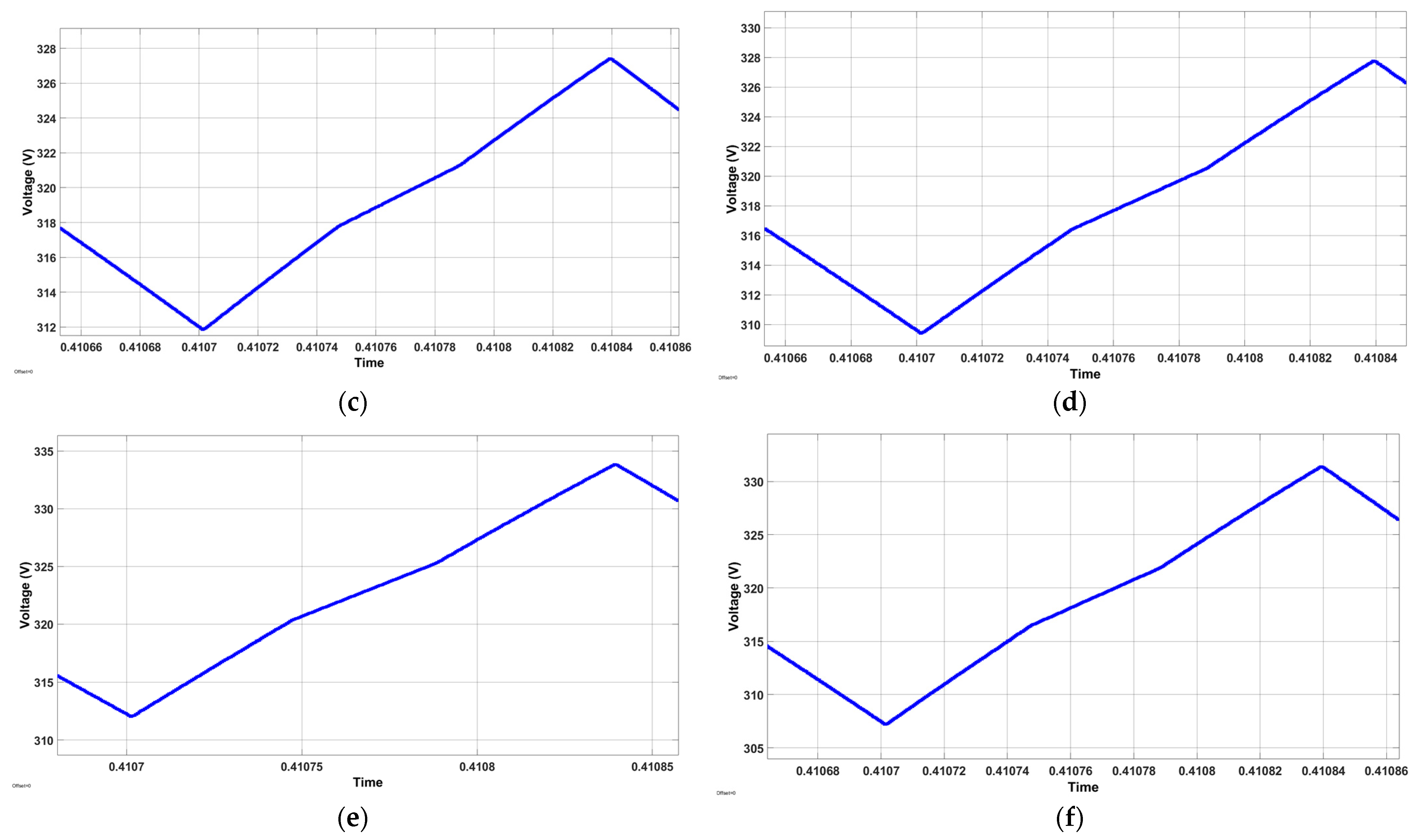
From
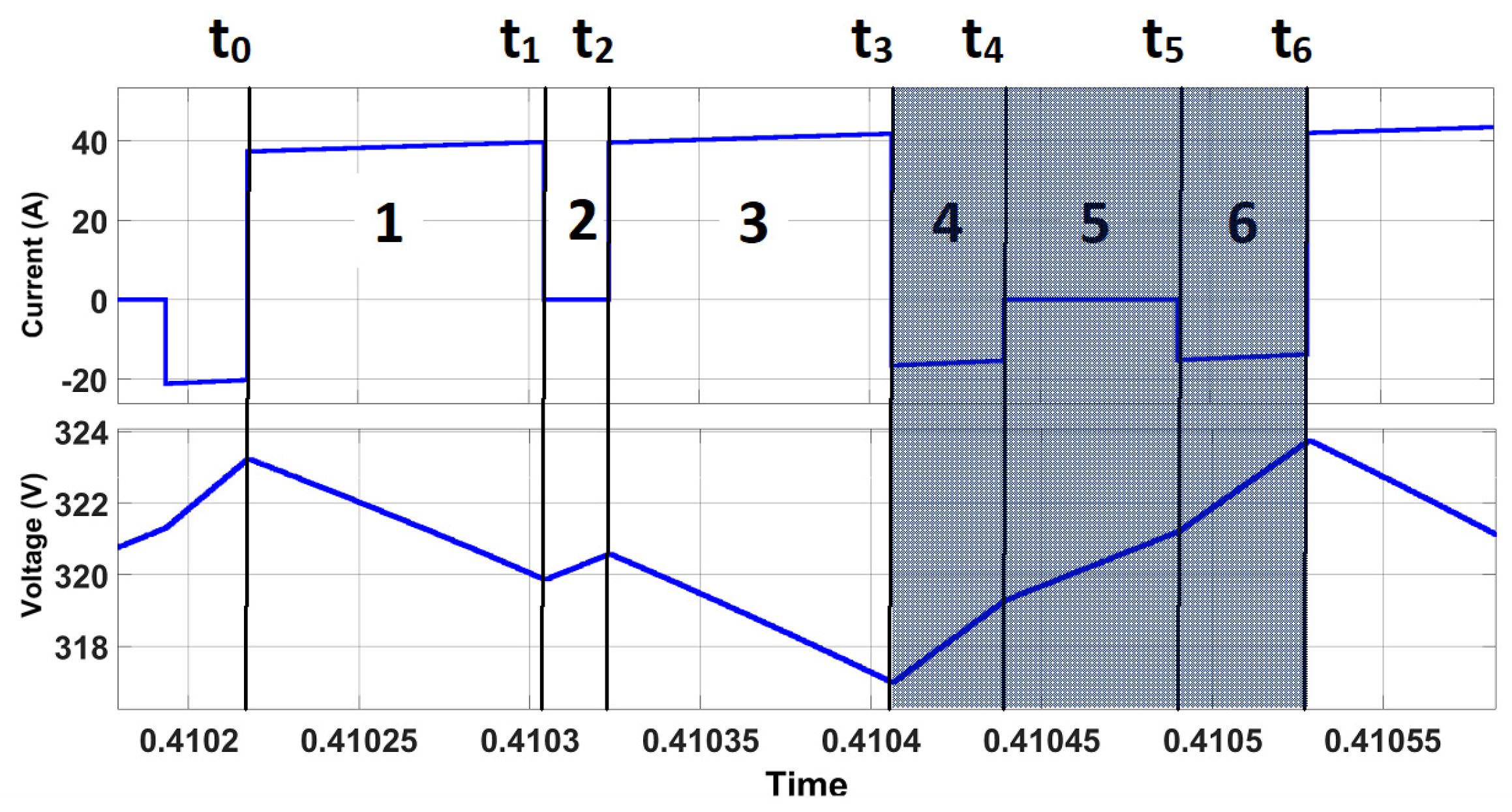
Figure 8, it can be seen that the pattern is directly affected by the switching signals. However, it was detected that a certain pattern is followed every six intervals. For this reason, the signal is sectioned to deduce the capacitance in the largest ripple presented (worst case),
Figure 9,
Table 3 defines the intervals. Observing that in sections four, five, and six is when the steepest positive slopes are presented, this indicates that these are the moments in which more energy is returned.
2.2. Development of a Mathematical Model
For the analysis and mathematical development of the proposed capacitance equation, the analysis of the currents presented in
Figure 10 are used as a starting point.
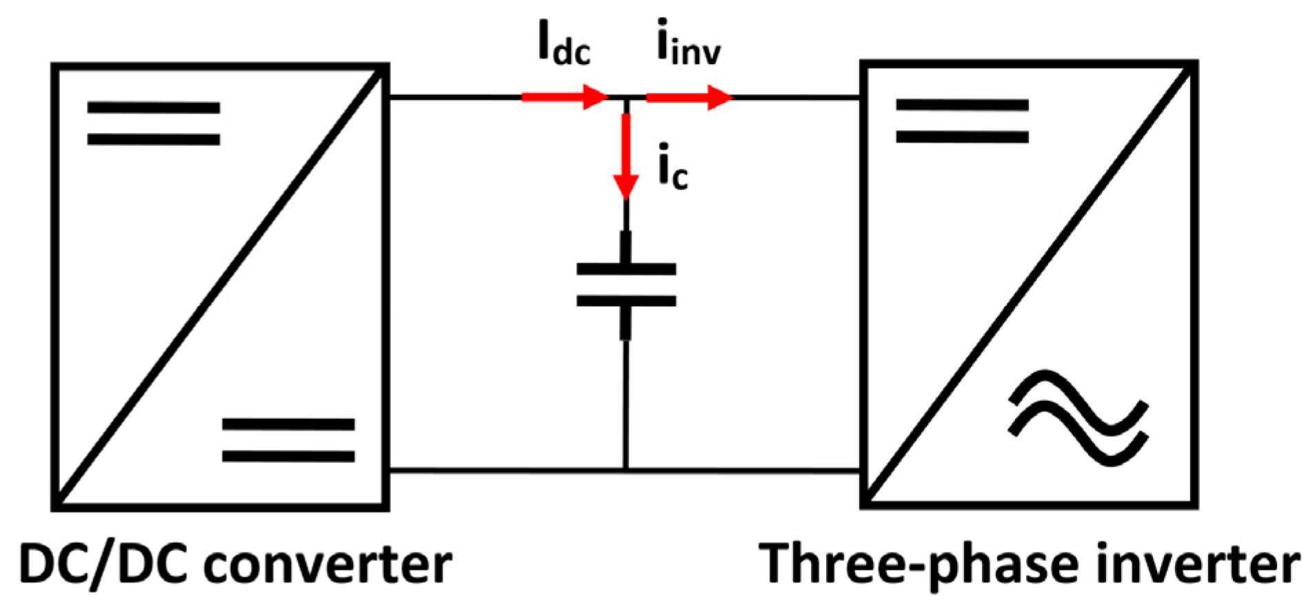
The development of the calculation of the minimum capacitance required is addressed in Equations (1)–(19), which start from Kirchhoff’s current law, taking as reference the incoming and outgoing currents in the decoupling circuit, as well as the operating mode of the load [
39,
40]. Subsequently, the data pertaining to the critical case of operation, which is characterized by the highest energy return to the decoupling circuit, is addressed. This analysis neglects the effects of heating and degradation of the DC-link.
Using Kirchhoff’s law of nodes, obtaining:
where
IDC is the DC–DC converter current;
iC is the capacitor current and
iinv is the inverter current.
Knowing that the capacitor current is equal to the capacitance multiplied by the derivative of the voltage across the capacitor concerning time (2). Substituting (2) in (1) we obtain (3):
where
C is the decoupling capacitance;
is the ratio of voltage change with respect to time.
The capacitance
C is solved from (3) and (4) assuming the derivatives as an increase in voltage value,
C is obtained with (5).
Subsequently, the ratio of the nominal power of the system with the power of the case study is determined, in which the critical point of returned energy is carried out because under this circumstance the capacitor must be able to handle the maximum variation. The above relation is performed employing proportionality factors, obtaining (6).
where
K is the general proportionality factor;
Pnom s is the nominal power of the system and
Pmáxreq is the worst-case power (case study).
Deducting
Pmáxreq from (6) (7) and (8) are obtained:
where
Imáxreq is the worst case current (study case) and
VDC is the DC–DC converter voltage. Equaling (7) and (8) we obtain (9). From this, the maximum current required in the worst case is obtained according to (10).
Considering the intervals discussed at the end of the previous section where the case study was selected. It is solved
of (11), considering the study times, obtaining (12):
However, as presented in
Figure 9 the current
Imáxreq5 of the intervals
t4 and
t5 are zero. Considering this solution (12) is obtained (13).
To obtain the inverter current in terms of power, (10) is substituted into (13), and (14) is obtained:
The proportionality factors K4 and K6 have a negative value derived from the direction of the current, which is returned from the load to the source.
Subsequently, it is sought to obtain a relationship between the intervals used in (14), concerning the inverter switching frequency used. This is because when varying said frequency, the duration of the intervals used in the capacitance equation developed is modified.
Through the analysis of the intervals in which the critical case occurs under the conditions established in the work. as well as the influence of the modulation in them, is obtained (15), which is used to calculate the time in which the maximum energy of the critical case is returned. Equation (15) represents the ratio of the complete interval, from T0 to T6 concerning the switching frequency.
where
fsw is the modulation switching frequency.
Once the dimension of the interval increment
is defined, the relation concerning
t4 and
t6 where the energy return occurs was determined, with (16) and (17), respectively. Equations (16) and (17) show the relation between the inverter switching frequency and the intervals in which energy is returned to the decoupling system. This returned energy is added to the energy managed by the DC-link, resulting in the critical case of maximum energy storage by the DC-link (critical case).
Equations (15)–(17) are used to determine the exact duration of the intervals when the switching frequency in the inverter varies.
Finally, substituting (14) in (5) and considering (18), the required capacitance equation is obtained with (19).
The negative sign of the K-factors represents the energy returned from the load to the source, which is added to the energy delivered by the source and together they represent the total energy stored in the link capacitor at that instant.

 ,
, 


