Communication

Entangled Frequency-Tunable Microwave Photons in a Superconducting Circuit

1
Research Institute of Superconductor Electronics, School of Electronic Science and Engineering, Nanjing University, Nanjing 210093, China
2
Hefei National Laboratory, Hefei 230088, China
3
Purple Mountain Laboratories, Nanjing 211111, China
*
Author to whom correspondence should be addressed.
Appl. Sci. 2023, 13(6), 3688; https://doi.org/10.3390/app13063688
Submission received: 4 February 2023 / Revised: 10 March 2023 / Accepted: 11 March 2023 / Published: 14 March 2023
(This article belongs to the Topic Quantum Information and Quantum Computing)

Abstract

:
We propose a frequency-tunable source to emit entangled microwave photons on the platform of a superconducting circuit, in which two superconducting transmission-line resonators are coupled via a capacitor and one resonator is inserted with a superconducting quantum interference device (SQUID) in the center. By pumping the circuit appropriately with an external coherent microwave signal through the SQUID, microwave photons are emitted in pairs out of the circuit. The entanglement between the two modes is demonstrated by numerically calculating the second-order coherence function and the logarithmic negativity of the output microwave signals. Due to the tunability of SQUID’s equivalent inductance, the frequencies of the entangled microwave photons can be tuned by an external flux bias in situ. Our proposal paves a new way for obtaining entangled frequency-tunable two-mode microwave photons.

1. Introduction

A source emitting entangled microwave photons is an indispensable quantum resource for quantum information processing [1,2]. It can be used in many quantum application technologies, for example, entangling distant superconducting qubits [3,4] and/or other physical qubits [5], realizing quantum key distribution [6,7,8] and quantum teleportation [9,10], acting as quantum repeaters and sensors [11], performing continuous-variable (CV) quantum computing [12], and accomplishing quantum illumination [13].
In the optical domain, using a nonlinear optical crystal to generate entangled photons with tunable frequency has been sufficiently investigated [14,15] through the spontaneous parametric down-conversion (SPDC) [16] in an optical parametric system. In the microwave domain, one promising physical candidate to construct such sources is superconducting devices [17,18,19,20]. One of the previous proposals takes advantage of cooper pairs tunneling in a Josephson junction [2]. However, it is difficult to tune the frequencies of entangled two-mode photons freely. Other proposals use the nonlinearity of SQUID with suitable parametric excitation [21,22,23,24,25] or the dynamical Casimir effect [26,27]. However, the entanglement property and frequency tunability are restricted to the nonlinearity of SQUID. A coplanar waveguide terminating with an asymmetric SQUID has also been used to construct a multi-mode superconducting crystal with its high-order nonlinearity, in which multi-mode SPDC entangled photons in the microwave domain are generated by suitably driving the SQUID [22,23,24]. However, the tunability of frequencies is limited by the Kerr-nonlinearity [28], and it is hard to excite the high-order modes with an external pump field [24]. Recently a Josephson ring modulator (JRM), a nonlinear device with four ports working as a three-wave mixer, has been applied to entangle two superconducting coplanar waveguide resonators (CPWRs) [29,30,31,32,33]. This kind of entanglement source uses the nonlinearity of JRM to emit entangled two-mode microwave signals under the proper external parametric excitement. Its tunable spectrum is limited due to the harsh working conditions for nonlinearity. Almost all the superconducting entanglement sources mentioned above need the nonlinearity originally provided by the Josephson junction. This limits the tunability of frequency due to the unstablity of nonlinearity at different working points. Therefore, building an entanglement source to emit entangled microwave photons without using the nonlinearity of Josephson junctions will increase the tunable frequency range, which is promising and attractive in the quantum information process.
In this paper, we propose a source of generating entangled frequency-tunable microwave photons with proper extra excitation to obtain a similar SPDC process in a superconducting quantum circuit, which is composed of a frequency-fixed resonator coupled to a frequency-tunable resonator. In other words, we construct a correlative microwave beam splitter that down-converts the coherent input microwave pump into two entangled microwave beams through the device. The photons are generated in pairs out of the system with a high level of entanglement characterized by the logarithmic negativity ( N ) [34]. The frequencies of the two inseparable modes can be tuned in situ by adjusting the external flux bias applied.

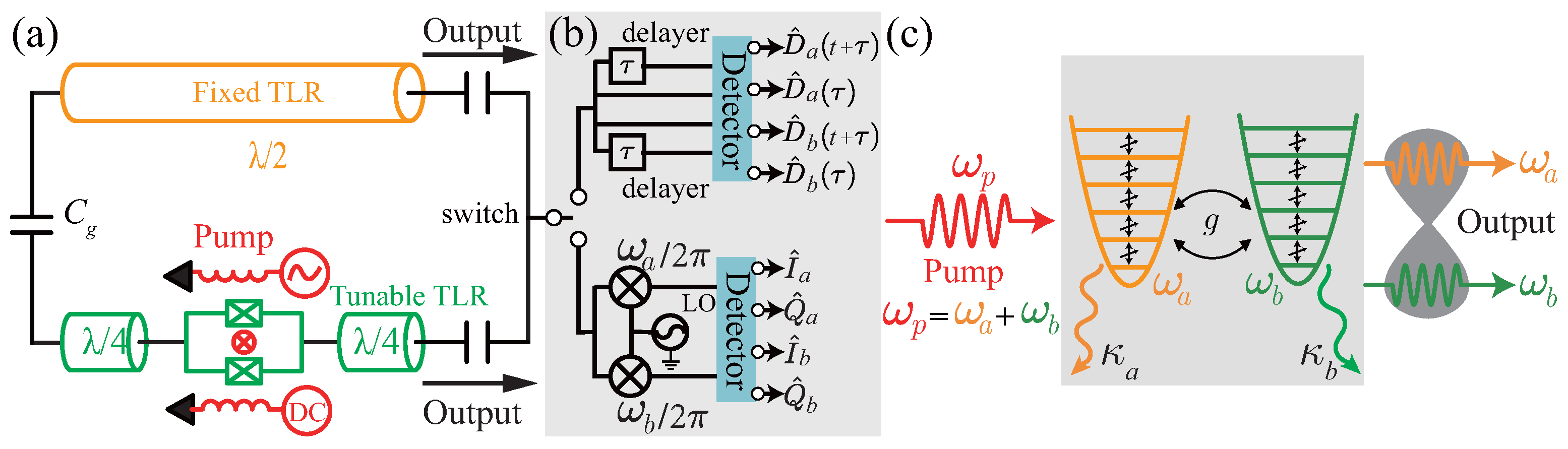
2. The Circuit Model

The circuit in our proposal is illustrated in Figure 1a. A frequency-fixed transmission-line resonator (TLR) (orange) is capacitively coupled to a frequency-tunable TLR (green), which is inserted with a SQUID in the center that behaves as a tunable inductance modulated by the flux bias through its loop. In the standard quantized manner, assuming that = 1 , the Hamiltonian of the circuit is
H ^ = H ^ a + H ^ b + H ^ a b = ω a a ^ a ^ + ω b b ^ b ^ g ( a ^ a ^ ) ( b ^ b ^ ) = ω a a ^ a ^ + ω b b ^ b ^ + g { ( a ^ b ^ + a ^ b ^ ) ( a ^ b ^ + a ^ b ^ ) } ,
where a ^ ( a ^ ) and b ^ ( b ^ ) are the annihilation (creation) operator of modes a and b, respectively, and ω a and ω b are the corresponding resonant angular frequencies of the two modes of our system, respectively. g is the capacitive coupling strength between the two modes. ( a ^ b ^ + a ^ b ^ ) is the rotating term, and ( a ^ b ^ + a ^ b ^ ) is the counterrotating (CR) term.
The two modes of the system come from the coupled resonators. The eigenfrequency of the frequency-fixed resonator (orange) is ω f . The resonant frequency of the frequency-tunable resonator (green) is ω t = ω t 0 / ( 1 + γ 0 cos ( π Φ dc / Φ 0 ) ) with geometric frequency ω t 0 , i.e., the resonant frequency without a SQUID. The participation ratio γ 0 is the ratio between the equivalent inductance of SQUID (at zero dc flux bias), and the inductance of the tunable resonator. Φ 0 = h / 2 e is the flux quantum. Then, the two different modes [35,36] of the superconducting circuit are
ω a = 1 2 ( ω f + ω t ) g 2 + ( Δ ω 2 ) 2 , ω b = 1 2 ( ω f + ω t ) + g 2 + ( Δ ω 2 ) 2 ,
where Δ ω = ω t ω f , and the coupling strength g = C g Z 0 ( 2 ω f 2 + ω t 2 ) / 2 π with impedance Z 0 of resonators. Here, we have set ω f = 5.416 GHz, ω t 0 = 5.844 GHz, γ 0 = 4.8%, C g = 5.1 fF and Z 0 = 50 Ω . The rates of decay into the environment of the two modes are κ a / 2 π = 0.02 GHz and κ b = 2 κ a , respectively.
Equation (1) describes the quantum states of two coupled modes. The entangled photons between the two modes hardly escape from the circuit without external energy excitation due to the usual neglect of the CR term in the rotating-wave approximation [35,36]. In our proposal, the high-frequency oscillation terms of the last part in Equation (1) are excited with the help of a strong external pump through the SQUID [37,38,39]. In this case, the resonant frequency of SQUID is modulated by Φ e = Φ dc + Φ ac periodically as
ω b ( t ) = ω b ( Φ dc ) + β sin ( ω p t + φ p 0 ) ,
where Φ dc is the dc flux bias and Φ ac = β sin ( ω p t + φ p 0 ) is a microwave pump. β , ω p , and φ p 0 are the amplitude, frequency, and initial phase of the pump field, respectively.
By moving the system into the rotating frame by defining the unitary operator as U ^ = U ^ 1 × U ^ 2 , in which
U ^ 1 = exp [ i ( ω a a ^ a ^ + ω b b ^ b ^ ) t ] , U ^ 2 = exp [ i α p cos ( ω p t + φ p 0 ) b ^ b ^ ] ,
with a dimensionless parameter α p = β / ω p , we can obtain the transformed Hamiltonian of the system
H ^ trans = U ^ H ^ U ^ i U ^ U ^ t = U ^ 2 U ^ 1 [ g ( a ^ a ^ ) ( b ^ b ^ ) ] U ^ 1 U ^ 2 = U ^ 2 g [ ( a ^ b ^ e i Δ t + H . c . ) ( a ^ b ^ e i Ω t + H . c . ) ] U ^ 2 = g { ( a ^ b ^ e i Δ t + H . c . ) × exp [ i α p cos ( ω p t + φ p 0 ) ] ( a ^ b ^ e i Ω t + H . c . ) × exp [ i α p cos ( ω p t + φ p 0 ) ] } ,
where Δ = ω a ω b , Ω = ω a + ω b . Then, the Jacobi–Anger identity with m-th order Bessel function of the first kind J m ( α p ) is used to expand the cosine oscillation of exponential term,
exp [ i α p cos ( ω p t + φ p 0 ) ] = m = m = i m J m ( α p ) exp [ i m ( ω p t + φ p 0 ) ] .
Now, we truncate Equation (6) into the order −1, 0, and 1 and set the initial phase φ p 0 to zero for convenience. Then, Equation (5) is reduced to
H ^ trans g { ( a ^ b ^ e i Δ t + H . c . ) × m = 1 m = 1 i m J m ( α p ) e i m ω p t ( a ^ b ^ e i Ω t + H . c . ) × m = 1 m = 1 ( i ) m J m ( α p ) e i m ω p t } .
The frequency of the pump field that we implement is a sum of resonant frequencies of the two modes, i.e., ω p = ω a + ω b . If the higher oscillation terms in the rotating-wave approximation are neglected, e.g., a ^ b ^ exp [ i ( ω p + Δ ) t ] and a ^ b ^ exp [ i ( ω p + Ω ) t ] , the Hamiltonian in the interaction picture of the circuit becomes
H ^ I = χ 0 ( a ^ b ^ e i Δ t + a ^ b ^ e i Δ t ) i χ 1 ( a ^ b ^ a ^ b ^ ) ,
with the effective couplings χ 0 = g J 0 ( α p ) and χ 1 = g J 1 ( α p ) . The first term is the swap interaction of states between the two modes, which means the two modes may exchange information with each other. The second term is the interaction between two oscillators, which is the origin of entanglement with the excitation of the pump field. In other words, the second term down-converts the coherent input microwave pump into two entangled microwave beams, which are similar to the signal and idle modes generated by the SPDC in the optical nonlinear system.

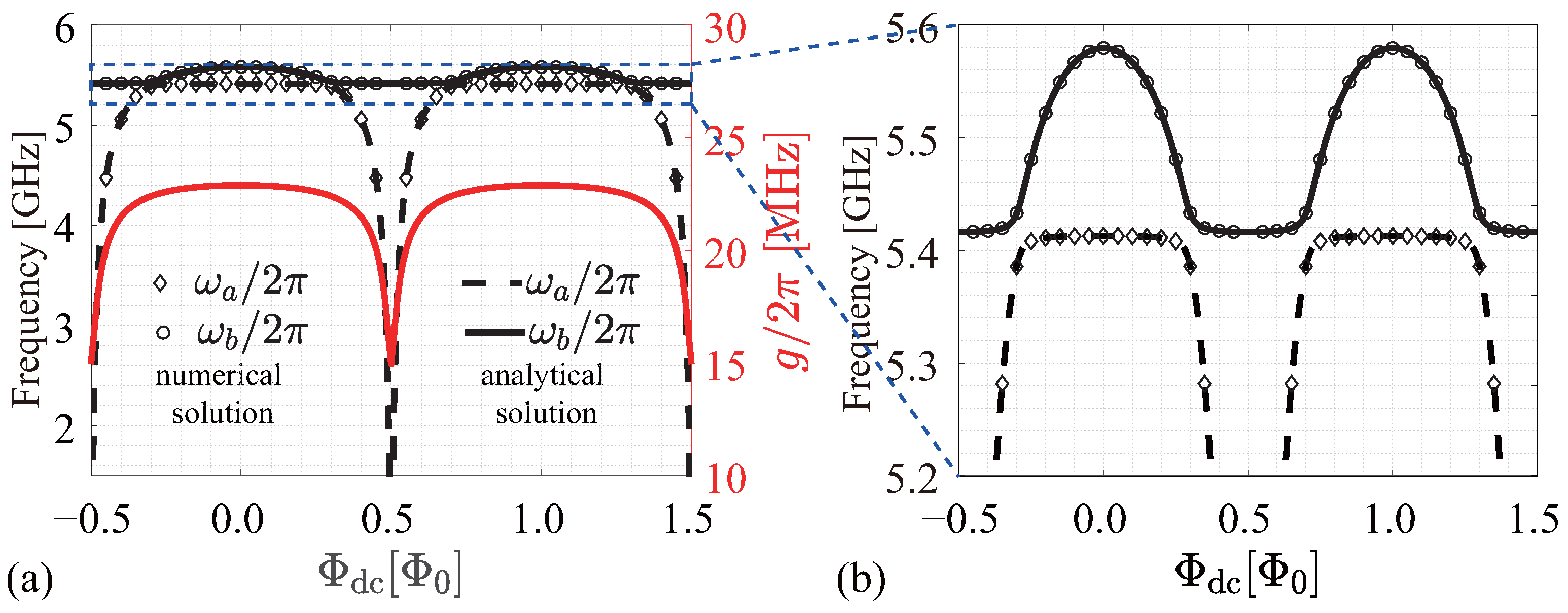
3. Parameters and Spectrum of the System

To demonstrate the feasibility of our proposed circuit, the parameters in the numerical simulation are set to the values that can be readily achieved experimentally with standard micro-fabrication techniques [35,36,40,41,42].
Using Equations (1) and (2) and the parameters mentioned above, we calculate the spectroscopy of the system with H ^ ( Φ dc ) | ψ = E ( Φ dc ) | ψ , where the eigenenergy E ( Φ dc ) = ω ( Φ dc ) is in the unit of frequency as shown in Figure 2. The numerical solutions to Equation (1) agree well with analytical solutions to Equation (2). Due to the existence of the coupling between the two modes, the spectroscopy has anti-crossings [35,36] in the vicinity of Φ dc = ( k + 0.5 ) Φ 0 ( k Z ). The coupling strength varies with the dc flux bias periodically as shown in Figure 2.
Figure 1b shows the proposed schematic measurement setups to characterize the quantum physical properties of the output fields of the source. These measurements have been realized in the research of continuous quantum variables in the superconducting nonlinear microwave circuits [27,29,43,44], with which we numerically demonstrate the entanglement property between the output signals in our proposed source.
Because the swapping of quantum states destroys the anisotropy of the entangled photons and transforms them into isotropy [45], the existence of swap interaction between different modes will reduce the entanglement of the continuous-variable microwave on average when the swap and entanglement interactions appear simultaneously. To eliminate the swap interaction with moderate radiation in the circuit, we apply a pump filed [37] with α p = 2.404 , which sets χ 0 0 and χ 1 0.519 g in Equation (8), as shown in Figure 3. Then, Equation (8) can be rewritten as
H ^ I = i χ 1 ( a ^ b ^ a ^ b ^ ) .

4. Numerical Results

4.1. Creation of the Photon Pairs

The system is initialized in the two-mode vacuum state | ψ v = | 0 , 0 with a ^ a ^ = b ^ b ^ 0 . Under the excitation of the pump field, the photons of the two modes are emitted out of the circuit; i.e., the input pump photons are split into two different modes when they pass through the superconducting circuit. The state of an emitter is | ψ | ψ a | ψ b , where | ψ a and | ψ b are the cavity Fock states with twenty dimensions R a and R b , respectively. R a and R b build the truncated Hilbert space G = R a R b (note that the increasing dimension of the truncated Hilbert space G does not significantly affect the numerical steady-state results of our system [46,47,48,49,50,51]). The output photon modes a and b can be described by the corresponding operator ρ ^ ( t ) and governed by the master equation, which describes the evolution of the quantum system as
d ρ ^ d t = i [ H ^ , ρ ^ ] + κ a D [ a ^ ] ρ ^ + κ b D [ b ^ ] ρ ^ ,
where D [ c ^ ] ρ ^ = c ^ ρ ^ c ^ c ^ c ^ ρ ^ / 2 ρ ^ c ^ c ^ / 2 , ( c ^ = a ^ , b ^ ) . D [ c ^ ] is the dissipative superoperator and κ a ( κ b ) is the decay rate of the mode a (b). Under the rotating wave approximation with the pump excitation, the master equation of our circuit with effective Hamiltonian H I ^ is
d ρ ˜ ^ d t = i [ H I ^ , ρ ˜ ^ ] + κ a D [ a ^ ] ρ ˜ ^ + κ b D [ b ^ ] ρ ˜ ^ ,
where the ρ ˜ ^ is the density matrix of the source under the rotating framework.
To demonstrate that the proposed circuit pumped by an external field will generate photons, we use QuTip [52,53] to numerically calculate the master equation of Equation (11) combined with Equation (9) at different working points Φ dc corresponding to different coupling strengths g. As shown in Figure 4a, the mean microwave photons of both modes flee from the system with the same tendency, which means the two modes are generated simultaneously and have an identical dependence on the coupling strength g, which is a function of Φ dc . Φ dc = 0 with a coupling strength g / 2 π = 22.889 MHz is selected as an example to demonstrate the detailed behavior in Figure 4b. In the steady state of the two modes, the mean photon number is a ^ a ^ 1.59 and b ^ b ^ 0.80, respectively. Note that we carry out the numerical calculations with the whole Hamiltonian of our system and compare the results with these calculated with the interaction Hamiltonian. No obvious difference is observed.
One can measure the bunching effect of the generated two different modes by observing D ^ j ( t ) , D ^ j ( t + τ ) ( j = a , b ), which represent the intensity of modes with a delay time τ (upper panel in Figure 1b) and record the photon statistics in the time domain. To further demonstrate that the photons are emitted in pairs simultaneously, we reconstruct the second-order coherence function g a b ( 2 ) ( t , τ ) of the output microwave signals at different dc working points using numerical simulation.
g a b ( 2 ) ( t , τ ) = : D ^ a ( t ) D ^ a ( t + τ ) D ^ b ( t + τ ) D ^ b ( t ) : D ^ a ( t ) D ^ b ( t ) a ^ ( t ) a ^ ( t + τ ) b ^ ( t + τ ) b ( t ) a ^ ( t ) a ^ ( t ) b ^ ( t ) b ^ ( t ) ,
where the dots :: denote the normal ordering.
As shown in Figure 5, we reconstruct the second-order coherence function with zero delay g a b ( 2 ) ( t , 0 ) at dc working points { 0.5 , 0.25 , 0.25 , 0.5 } Φ 0 . The g a b ( 2 ) ( t , 0 ) starts from a high value, which means the output microwave photons between the two modes are emitted in pairs out of the emitter at all dc working points. The g a b ( 2 ) ( t , 0 ) decreases significantly as time goes on due to the losses of both resonators, which destroy the correlation between both modes, and also due to the increase in photon number as shown in the Figure 4b.

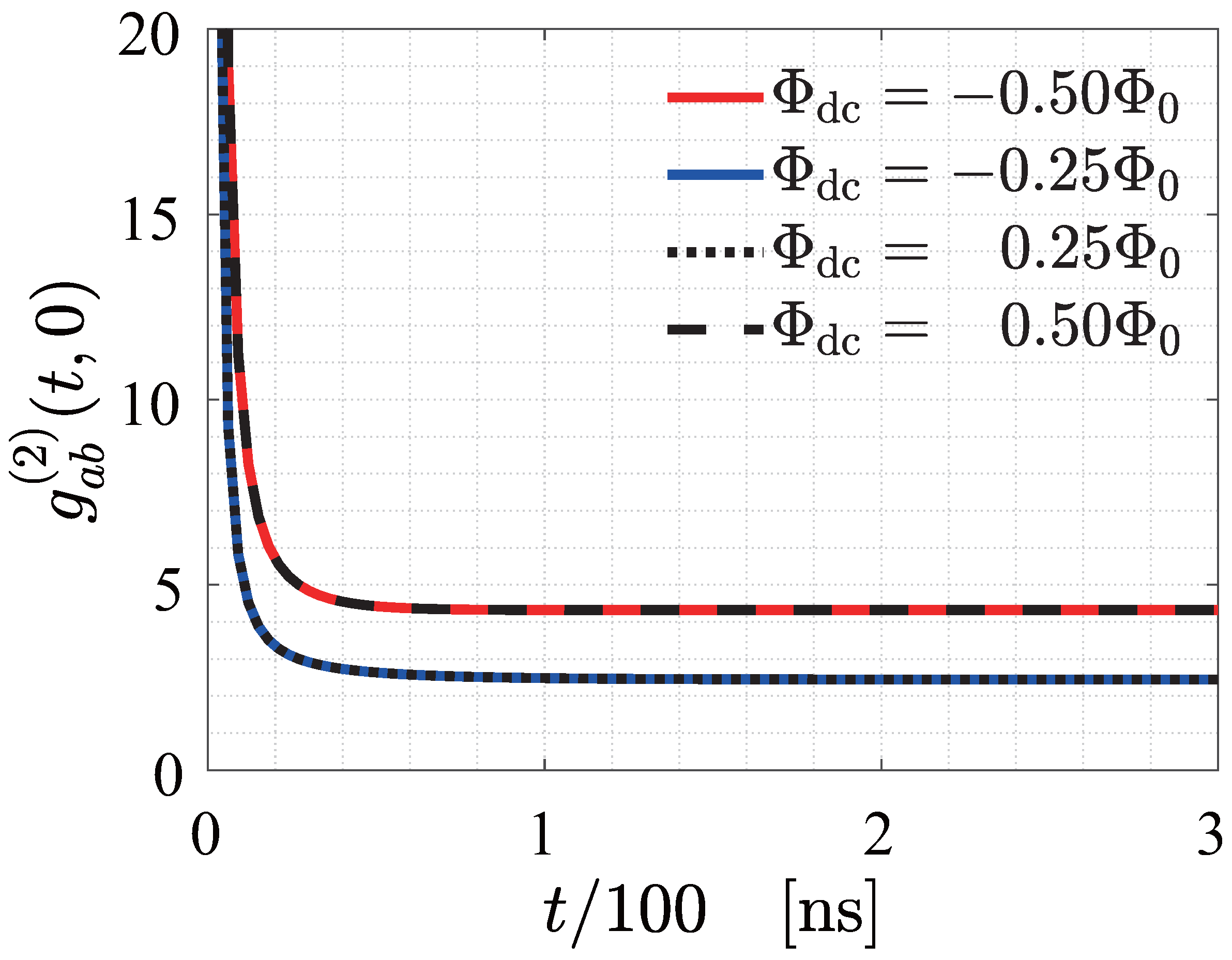
4.2. Two-Mode Entanglement

Using path entanglement detection is a straightforward and accurate way to characterize the quality of entanglement of the photons generated from the continuous-variable entanglement source [22,27,30,33,43]. We numerically calculate the in-phase I ^ a , I ^ b , and quadrature Q ^ a , Q ^ b values of the two modes (lower panel in Figure 1b) to reconstruct the 4 × 4 covariance matrix V containing the information between the two modes in the phase space
V α β = 1 2 R ^ α R ^ β + R ^ β R ^ α ,
where α , β = { 1 , 2 , 3 , 4 } , R ^ = { I ^ a , Q ^ a , I ^ b , Q ^ b } and
I ^ a = ( a ^ + a ^ ) / 2 , Q ^ a = i ( a ^ a ^ ) / 2 ,
I ^ b = ( b ^ + b ^ ) / 2 , Q ^ b = i ( b ^ b ^ ) / 2 .
With the covariance matrix, it is convenient to build the logarithmic negativity N , and N > 0 means entanglement [34].
N = max [ 0 , log ( 2 ξ ) ] , ξ = [ λ / 2 ( λ 2 det V ) 1 / 2 / 2 ] 1 / 2 , λ = det A + det B 2 det C , V = A C C T B .
The 2 × 2 submatrices A, B, and C compose the covariance matrix V. The diagonal submatrices A and B are the phase-space distributions of modes a and b, respectively, and the off-diagonal matrix C and its transposed matrix C T indicate the correlation between the two modes in the phase space.
Figure 6a shows the inseparable level of the two modes characterized by N at different working points in the time domain with continuous pump driving. The tendency of entanglement between the two modes is similar at different working points, and the value of N of steady states is different, especially near Φ dc = ± 0.50 Φ 0 due to the different coupling strength g in one period. Figure 6b shows the detailed N at Φ dc = 0 , i.e., g / 2 π = 22.889 MHz. The inset of Figure 6b is a visualization of the covariance matrix V when the state of the system becomes steady. The diagonal elements of C and C T are non-zero, indicating the strong correlation between the two modes.

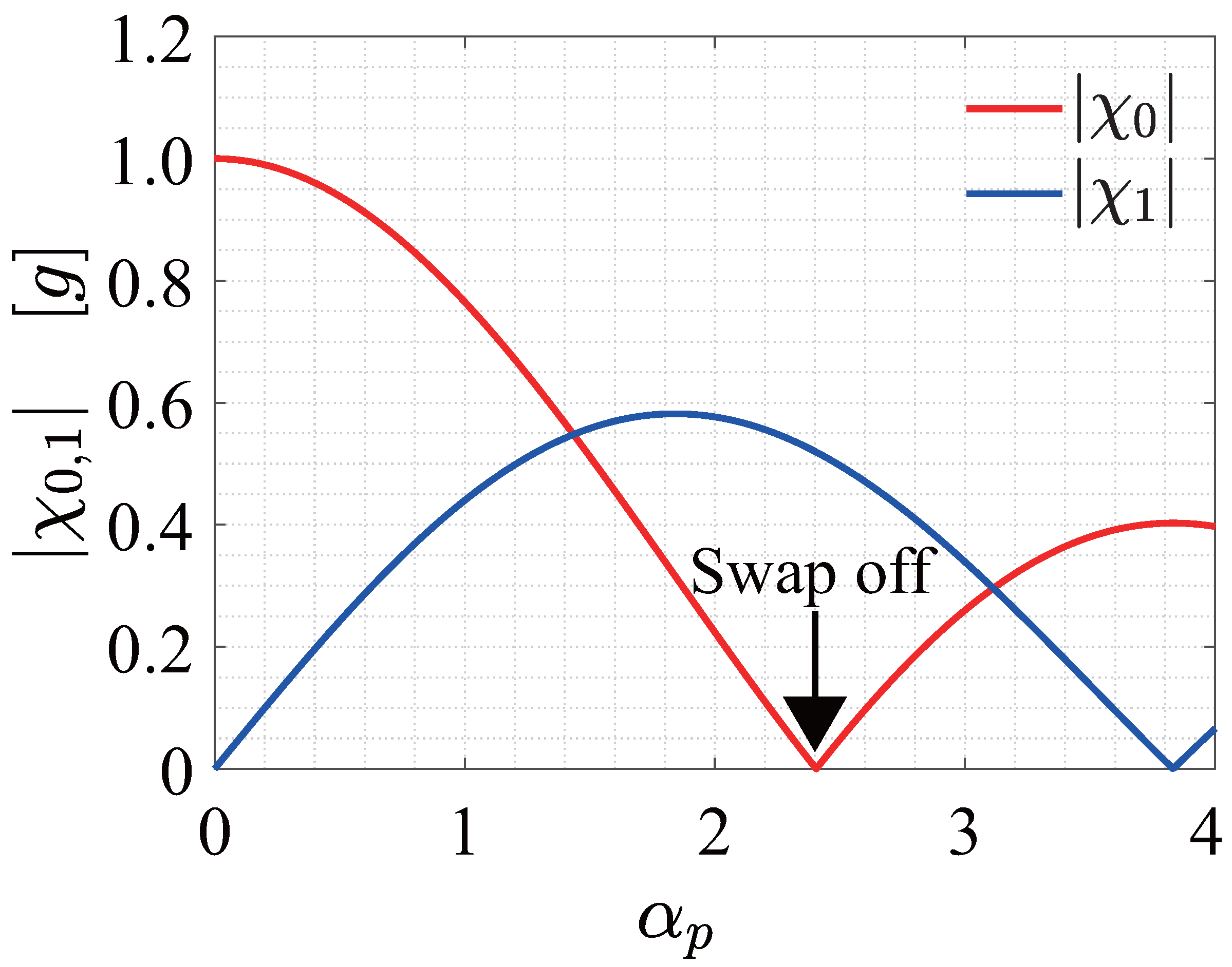
4.3. Frequency-Tunable Entangled Photon Pairs

Due to the tunability of SQUID, which acts as a tunable inductance in the frequency-tunable TLR, ω a ( Φ dc ) and ω b ( Φ dc ) can be adjusted by an external dc flux bias in situ. By implementing proper pump power according to the pump frequency, one can make the emitted pairwise photons reach a steady entanglement at each working point.
We record N as a standard to evaluate the degree of entanglement as well as the frequencies of the emitted two-mode signals with corresponding pump frequency ω p ( Φ dc ) = ω a ( Φ dc ) + ω b ( Φ dc ) . As shown in Figure 6c,d, pairwise photons with varied frequencies at different working points are generated in the range of 4 GHz. The saturated entanglement is stable around N = 0.5. Note that the equivalent inductance of SQUID has larger Kerr-nonlinearity when it works in the vicinity of ( k + 0.5 ) Φ 0 ( k Z ) [28]. In addition, the strong pump field may induce a shift in resonant frequencies [33,54,55,56]. These two factors will modify the frequencies of the two modes and are worthy of attention in the tuning of the source. In low temperatures such as 10 mK, the effect of thermal excitation on the properties of our circuit can be neglected, which is proved by our numerical calculations. The effect of decoherence is dominated by the decay rates κ a and κ b of the system.

5. Conclusions

In conclusion, we propose a microwave source that can emit entangled frequency-tunable microwave photons. The photons are emitted in pairs from the circuit with suitable parameters set in the pump field. The two output microwave packets with different frequencies are strongly entangled at every working point. Due to the tunability of the equivalent inductance of SQUID, the frequencies of the entangled photons can be tuned in situ, which is an important quantum resource in the quantum information process.

Author Contributions

Conceptualization, K.Z. and G.S.; Data curation, K.Z.; Investigation, K.Z., C.C., J.C., H.W., G.S. and P.W.; Methodology, K.Z.; Supervision, G.S.; Visualization, K.Z.; Writing original draft, K.Z. and G.S.; Writing review and editing, K.Z., C.C., J.C., H.W., G.S. and P.W.; Funding acquisition, G.S., P.W. All authors have read and agreed to the published version of the manuscript.

Funding

This work was partially supported by the Innovation Program for Quantum Science and Technology (2021ZD0301701), the National Natural Science Foundation of China (Grant No. 62288101), PAPD, the Fundamental Research Funds for the Central Universities (021014380192) and Dengfeng Project B of Nanjing University.

Institutional Review Board Statement

Not applicable.

Informed Consent Statement

Not applicable.

Data Availability Statement

Data sharing not applicable.

Acknowledgments

We thank Zhengyuan Xue, Jiazheng Pan, Yapeng Lu, Xingyu Wei, Junliang Jiang, Zishuo Li, Tingting Guo, Wenqu Xu, Quan Zuo, Shuo Wang, Tianshi Zhou, Hancong Sun, and Jinpeng Li for valuable discussions.

Conflicts of Interest

The authors declare no conflict of interest in this article.

References

  1. Wendin, G. Quantum information processing with superconducting circuits: A review. Rep. Prog. Phys. 2017, 80, 106001. [Google Scholar] [CrossRef] [Green Version]
  2. Peugeot, A.; Ménard, G.; Dambach, S.; Westig, M.; Kubala, B.; Mukharsky, Y.; Altimiras, C.; Joyez, P.; Vion, D.; Roche, P.; et al. Generating Two Continuous Entangled Microwave Beams Using a dc-Biased Josephson Junction. Phys. Rev. X 2021, 11, 031008. [Google Scholar] [CrossRef]
  3. Felicetti, S.; Sanz, M.; Lamata, L.; Romero, G.; Johansson, G.; Delsing, P.; Solano, E. Dynamical Casimir Effect Entangles Artificial Atoms. Phys. Rev. Lett. 2014, 113, 093602. [Google Scholar] [CrossRef] [Green Version]
  4. Agustí, A.; Solano, E.; Sabín, C. Entanglement through qubit motion and the dynamical Casimir effect. Phys. Rev. A 2019, 99, 052328. [Google Scholar] [CrossRef] [Green Version]
  5. Gómez, A.V.; Rodríguez, F.J.; Quiroga, L. Cross-entangling electronic and nuclear spins of distant nitrogen-vacancy centers in noisy environments by means of quantum microwave radiation. Phys. Rev. B 2018, 98, 075114. [Google Scholar] [CrossRef] [Green Version]
  6. Braunstein, S.L.; van Loock, P. Quantum information with continuous variables. Rev. Mod. Phys. 2005, 77, 513–577. [Google Scholar] [CrossRef] [Green Version]
  7. Xu, F.; Ma, X.; Zhang, Q.; Lo, H.K.; Pan, J.W. Secure quantum key distribution with realistic devices. Rev. Mod. Phys. 2020, 92, 025002. [Google Scholar] [CrossRef]
  8. Huang, D.; Huang, P.; Lin, D.K.; Wang, C.; Zeng, G.H. High-speed continuous-variable quantum key distribution without sending a local oscillator. Opt. Lett. 2015, 40, 3695–3698. [Google Scholar] [CrossRef] [PubMed]
  9. Wang, J.; Sciarrino, F.; Laing, A.; Thompson, M.G. Integrated photonic quantum technologies. Nat. Photonics 2020, 14, 273–284. [Google Scholar] [CrossRef]
  10. Bruzewicz, C.D.; Chiaverini, J.; McConnell, R.; Sage, J.M. Trapped-ion quantum computing: Progress and challenges. Appl. Phys. Rev. 2019, 6, 021314. [Google Scholar] [CrossRef] [Green Version]
  11. Reiserer, A.; Rempe, G. Cavity-based quantum networks with single atoms and optical photons. Rev. Mod. Phys. 2015, 87, 1379–1418. [Google Scholar] [CrossRef] [Green Version]
  12. Hillmann, T.; Quijandría, F.; Johansson, G.; Ferraro, A.; Gasparinetti, S.; Ferrini, G. Universal Gate Set for Continuous-Variable Quantum Computation with Microwave Circuits. Phys. Rev. Lett. 2020, 125, 160501. [Google Scholar] [CrossRef] [PubMed]
  13. Barzanjeh, S.; Pirandola, S.; Vitali, D.; Fink, J.M. Microwave quantum illumination using a digital receiver. Sci. Adv. 2020, 6. [Google Scholar] [CrossRef] [PubMed]
  14. Friberg, S.; Hong, C.K.; Mandel, L. Measurement of Time Delays in the Parametric Production of Photon Pairs. Phys. Rev. Lett. 1985, 54, 2011–2013. [Google Scholar] [CrossRef]
  15. Burnham, D.C.; Weinberg, D.L. Observation of Simultaneity in Parametric Production of Optical Photon Pairs. Phys. Rev. Lett. 1970, 25, 84–87. [Google Scholar] [CrossRef]
  16. Introini, V.; Steel, M.J.; Sipe, J.E.; Helt, L.G.; Liscidini, M. Spontaneous parametric down conversion in a doubly resonant one-dimensional photonic crystal. Opt. Lett. 2020, 45, 1244–1247. [Google Scholar] [CrossRef]
  17. Gosner, J.; Kubala, B.; Ankerhold, J. Relaxation dynamics and dissipative phase transition in quantum oscillators with period tripling. Phys. Rev. B 2020, 101, 054501. [Google Scholar] [CrossRef] [Green Version]
  18. Arndt, L.; Hassler, F. Period tripling due to Josephson parametric down-conversion beyond the rotating-wave approximation. Phys. Rev. B 2022, 106, 014513. [Google Scholar] [CrossRef]
  19. Arndt, L.; Hassler, F. Period Tripling due to Parametric Down-Conversion in Circuit QED. Phys. Rev. Lett. 2022, 128, 187701. [Google Scholar] [CrossRef]
  20. Denisenko, M.; Munyayev, V.; Satanin, A. Quantum fractional resonances in superconducting circuits with an embedded Josephson junction. J. Phys. Conf. Ser. 2016, 681, 012018. [Google Scholar] [CrossRef]
  21. Wilson, C.M.; Duty, T.; Sandberg, M.; Persson, F.; Shumeiko, V.; Delsing, P. Photon Generation in an Electromagnetic Cavity with a Time-Dependent Boundary. Phys. Rev. Lett. 2010, 105, 233907. [Google Scholar] [CrossRef] [PubMed] [Green Version]
  22. Sandbo Chang, C.W.; Simoen, M.; Aumentado, J.; Sabín, C.; Forn-Díaz, P.; Vadiraj, A.M.; Quijandría, F.; Johansson, G.; Fuentes, I.; Wilson, C.M. Generating Multimode Entangled Microwaves with a Superconducting Parametric Cavity. Phys. Rev. Appl. 2018, 10, 044019. [Google Scholar] [CrossRef]
  23. Agustí, A.; Chang, C.W.S.; Quijandría, F.; Johansson, G.; Wilson, C.M.; Sabín, C. Tripartite Genuine Non-Gaussian Entanglement in Three-Mode Spontaneous Parametric Down-Conversion. Phys. Rev. Lett. 2020, 125, 020502. [Google Scholar] [CrossRef] [PubMed]
  24. Chang, C.W.S.; Sabín, C.; Forn-Díaz, P.; Quijandría, F.; Vadiraj, A.M.; Nsanzineza, I.; Johansson, G.; Wilson, C.M. Observation of Three-Photon Spontaneous Parametric Down-Conversion in a Superconducting Parametric Cavity. Phys. Rev. X 2020, 10, 011011. [Google Scholar] [CrossRef] [Green Version]
  25. Wustmann, W.; Shumeiko, V. Parametric effects in circuit quantum electrodynamics. Low Temp. Phys. 2019, 45, 848–869. [Google Scholar] [CrossRef] [Green Version]
  26. Wilson, C.M.; Johansson, G.; Pourkabirian, A.; Simoen, M.; Johansson, J.R.; Duty, T.; Nori, F.; Delsing, P. Observation of the dynamical Casimir effect in a superconducting circuit. Nature 2011, 479, 376–379. [Google Scholar] [CrossRef] [Green Version]
  27. Schneider, B.H.; Bengtsson, A.; Svensson, I.M.; Aref, T.; Johansson, G.; Bylander, J.; Delsing, P. Observation of Broadband Entanglement in Microwave Radiation from a Single Time-Varying Boundary Condition. Phys. Rev. Lett. 2020, 124, 140503. [Google Scholar] [CrossRef] [Green Version]
  28. Krantz, P.; Reshitnyk, Y.; Wustmann, W.; Bylander, J.; Gustavsson, S.; Oliver, W.D.; Duty, T.; Shumeiko, V.; Delsing, P. Investigation of nonlinear effects in Josephson parametric oscillators used in circuit quantum electrodynamics. New J. Phys. 2013, 15, 105002. [Google Scholar] [CrossRef] [Green Version]
  29. Bergeal, N.; Schackert, F.; Frunzio, L.; Devoret, M.H. Two-Mode Correlation of Microwave Quantum Noise Generated by Parametric Down-Conversion. Phys. Rev. Lett. 2012, 108, 123902. [Google Scholar] [CrossRef] [Green Version]
  30. Marković, D.; Jezouin, S.; Ficheux, Q.; Fedortchenko, S.; Felicetti, S.; Coudreau, T.; Milman, P.; Leghtas, Z.; Huard, B. Demonstration of an Effective Ultrastrong Coupling between Two Oscillators. Phys. Rev. Lett. 2018, 121, 040505. [Google Scholar] [CrossRef] [Green Version]
  31. Flurin, E.; Roch, N.; Mallet, F.; Devoret, M.H.; Huard, B. Generating Entangled Microwave Radiation Over Two Transmission Lines. Phys. Rev. Lett. 2012, 109, 183901. [Google Scholar] [CrossRef] [Green Version]
  32. Fedortchenko, S.; Felicetti, S.; Marković, D.; Jezouin, S.; Keller, A.; Coudreau, T.; Huard, B.; Milman, P. Quantum simulation of ultrastrongly coupled bosonic modes using superconducting circuits. Phys. Rev. A 2017, 95, 042313. [Google Scholar] [CrossRef] [Green Version]
  33. Flurin, E.; Roch, N.; Pillet, J.D.; Mallet, F.; Huard, B. Superconducting Quantum Node for Entanglement and Storage of Microwave Radiation. Phys. Rev. Lett. 2015, 114, 090503. [Google Scholar] [CrossRef] [Green Version]
  34. Johansson, J.R.; Johansson, G.; Wilson, C.M.; Delsing, P.; Nori, F. Nonclassical microwave radiation from the dynamical Casimir effect. Phys. Rev. A 2013, 87, 043804. [Google Scholar] [CrossRef] [Green Version]
  35. Pierre, M.; Sathyamoorthy, S.R.; Svensson, I.M.; Johansson, G.; Delsing, P. Resonant and off-resonant microwave signal manipulation in coupled superconducting resonators. Phys. Rev. B 2019, 99, 094518. [Google Scholar] [CrossRef] [Green Version]
  36. Pierre, M.; Svensson, I.M.; Raman Sathyamoorthy, S.; Johansson, G.; Delsing, P. Storage and on-demand release of microwaves using superconducting resonators with tunable coupling. Appl. Phys. Lett. 2014, 104, 232604. [Google Scholar] [CrossRef] [Green Version]
  37. Strand, J.D.; Ware, M.; Beaudoin, F.; Ohki, T.A.; Johnson, B.R.; Blais, A.; Plourde, B.L.T. First-order sideband transitions with flux-driven asymmetric transmon qubits. Phys. Rev. B 2013, 87, 220505. [Google Scholar] [CrossRef] [Green Version]
  38. Xue, Z.Y.; Zhou, J.; Wang, Z.D. Universal holonomic quantum gates in decoherence-free subspace on superconducting circuits. Phys. Rev. A 2015, 92, 022320. [Google Scholar] [CrossRef] [Green Version]
  39. Xu, Y.; Cai, W.; Ma, Y.; Mu, X.; Hu, L.; Chen, T.; Wang, H.; Song, Y.P.; Xue, Z.Y.; Yin, Z.Q.; et al. Single-Loop Realization of Arbitrary Nonadiabatic Holonomic Single-Qubit Quantum Gates in a Superconducting Circuit. Phys. Rev. Lett. 2018, 121, 110501. [Google Scholar] [CrossRef] [Green Version]
  40. DiCarlo, L.; Chow, J.M.; Gambetta, J.M.; Bishop, L.S.; Johnson, B.R.; Schuster, D.I.; Majer, J.; Blais, A.; Frunzio, L.; Girvin, S.M.; et al. Demonstration of two-qubit algorithms with a superconducting quantum processor. Nature 2009, 460, 240–244. [Google Scholar] [CrossRef]
  41. Arute, F.; Arya, K.; Babbush, R.; Bacon, D.; Bardin, J.C.; Barends, R.; Biswas, R.; Boixo, S.; Brandao, F.G.S.L.; Buell, D.A.; et al. Quantum supremacy using a programmable superconducting processor. Nature 2019, 574, 505–510. [Google Scholar] [CrossRef] [Green Version]
  42. Gong, M.; Wang, S.; Zha, C.; Chen, M.C.; Huang, H.L.; Wu, Y.; Zhu, Q.; Zhao, Y.; Li, S.; Guo, S.; et al. Quantum walks on a programmable two-dimensional 62-qubit superconducting processor. Science 2021, 372, 948–952. [Google Scholar] [CrossRef]
  43. Eichler, C.; Bozyigit, D.; Lang, C.; Baur, M.; Steffen, L.; Fink, J.M.; Filipp, S.; Wallraff, A. Observation of Two-Mode Squeezing in the Microwave Frequency Domain. Phys. Rev. Lett. 2011, 107, 113601. [Google Scholar] [CrossRef] [Green Version]
  44. Johansson, J.R.; Johansson, G.; Wilson, C.M.; Nori, F. Dynamical Casimir effect in superconducting microwave circuits. Phys. Rev. A 2010, 82, 052509. [Google Scholar] [CrossRef] [Green Version]
  45. Wang, G.; Xiao, R.; Shen, H.Z.; Sun, C.; Xue, K. Simulating Anisotropic quantum Rabi model via frequency modulation. Sci. Rep. 2019, 9, 4569. [Google Scholar] [CrossRef] [Green Version]
  46. Rossatto, D.Z.; Felicetti, S.; Eneriz, H.; Rico, E.; Sanz, M.; Solano, E. Entangling polaritons via dynamical Casimir effect in circuit quantum electrodynamics. Phys. Rev. B 2016, 93, 094514. [Google Scholar] [CrossRef] [Green Version]
  47. Di Stefano, O.; Settineri, A.; Macrì, V.; Ridolfo, A.; Stassi, R.; Kockum, A.F.; Savasta, S.; Nori, F. Interaction of Mechanical Oscillators Mediated by the Exchange of Virtual Photon Pairs. Phys. Rev. Lett. 2019, 122, 030402. [Google Scholar] [CrossRef] [PubMed] [Green Version]
  48. Macrì, V.; Ridolfo, A.; Di Stefano, O.; Kockum, A.F.; Nori, F.; Savasta, S. Nonperturbative Dynamical Casimir Effect in Optomechanical Systems: Vacuum Casimir-Rabi Splittings. Phys. Rev. X 2018, 8, 011031. [Google Scholar] [CrossRef] [Green Version]
  49. Minganti, F.; Garbe, L.; Le Boité, A.; Felicetti, S. Non-Gaussian superradiant transition via three-body ultrastrong coupling. Phys. Rev. A 2023, 107, 013715. [Google Scholar] [CrossRef]
  50. Seifoory, H.; Doutre, S.; Dignam, M.M.; Sipe, J.E. Squeezed thermal states: The result of parametric down conversion in lossy cavities. J. Opt. Soc. Am. B 2017, 34, 1587–1596. [Google Scholar] [CrossRef]
  51. Salmon, W.; Gustin, C.; Settineri, A.; Stefano, O.D.; Zueco, D.; Savasta, S.; Nori, F.; Hughes, S. Gauge-independent emission spectra and quantum correlations in the ultrastrong coupling regime of open system cavity-QED. Nanophotonics 2022, 11, 1573–1590. [Google Scholar] [CrossRef]
  52. Johansson, J.; Nation, P.; Nori, F. QuTiP: An open-source Python framework for the dynamics of open quantum systems. Comput. Phys. Commun. 2012, 183, 1760–1772. [Google Scholar] [CrossRef] [Green Version]
  53. Johansson, J.; Nation, P.; Nori, F. QuTiP 2: A Python framework for the dynamics of open quantum systems. Comput. Phys. Commun. 2013, 184, 1234–1240. [Google Scholar] [CrossRef] [Green Version]
  54. Novikova, I.; Gorshkov, A.V.; Phillips, D.F.; Sørensen, A.S.; Lukin, M.D.; Walsworth, R.L. Optimal Control of Light Pulse Storage and Retrieval. Phys. Rev. Lett. 2007, 98, 243602. [Google Scholar] [CrossRef] [Green Version]
  55. Sete, E.A.; Mlinar, E.; Korotkov, A.N. Robust quantum state transfer using tunable couplers. Phys. Rev. B 2015, 91, 144509. [Google Scholar] [CrossRef] [Green Version]
  56. Caves, C.M.; Combes, J.; Jiang, Z.; Pandey, S. Quantum limits on phase-preserving linear amplifiers. Phys. Rev. A 2012, 86, 063802. [Google Scholar] [CrossRef] [Green Version]
Figure 1. (a) Equivalent circuit of our proposed scheme to emit entangled frequency-tunable microwave photons. A λ / 2 frequency-fixed TLR (orange) coupled to a λ / 2 frequency-tunable TLR (green) via a coupling capacitor C g . The tunable resonator is inserted with a SQUID that is composed of two identical Josephson junctions. The SQUID is driven by an external direct current (dc) flux bias Φ dc and a continuous microwave tone (ac) Φ ac . The output signals are processed by a detector. (b) (Upper panel) A proposed sketch of a setup for detecting the correlations of output photons. The second-order coherence function can be calculated by recording the intensities of modes such as D ^ a ( t ) , D ^ a ( t + τ ) , D ^ b ( t ) , and D ^ b ( t + τ ) . (Lower panel) A proposed schematic to observe the in-phase and quadrature voltages of output signals from the circuit. The emitted microwave signals are demodulated via a local oscillator (LO) and into the detector for calculating the quadrature components, which can be used to reconstruct the quantum properties of output signals using I ^ a , Q ^ a , I ^ b , and Q ^ b for modes a and b. (c) Model of generating the entangled microwave photons. The green and orange energy levels represent the harmonic behavior of modes a and b. κ a and κ b are the rates of decay into the environment of the two modes a and b, respectively. The curves with double arrows indicate the coupling between two oscillators. The red microwave signal denotes the extra pump field. The dark gray oval is the output envelope consisting of the entangled modes a and b.
Applsci 13 03688 g001
Figure 2. (a) Spectroscopy of the circuit as a function of the dc flux bias Φ dc . The dashed (solid) black line (left axis) represents the resonant frequency ω a / 2 π ( ω b / 2 π ) of the mode a (b) with analytical solutions using Equation (2). The data marked by diamonds and circles are the numerical solutions according to Equation (1). The red line (right axis) is the effective coupling strength g / 2 π . (b) The enlarged view of the blue dashed box in (a) explicitly displays the anti-crossings between the two modes.
Applsci 13 03688 g002
Figure 3. Dependence of the Bessel function of the first kind of order 0 (red) and 1 (blue) on the dimensionless parameter α p of the pump field, which determines the strength of χ 0 , 1 , where α p = 2.404 is chosen to eliminate the swap interaction between the two modes.
Applsci 13 03688 g003
Figure 4. (a) Photon number of modes a and b as functions of the dc flux bias Φ dc in the time domain. (b) Detailed photon creation along the horizontal white dashed line in (a) with Φ dc = 0 where the red line (right axis) is the second-order coherence functions g a b ( 2 ) ( t , 0 ) between the two modes with zero delay.
Applsci 13 03688 g004
Figure 5. The second-order coherence functions g a b ( 2 ) ( t , 0 ) of the output photons at dc working points { 0.5 , 0.25 , 0.25 , 0.5 } Φ 0 with zero delay.
Applsci 13 03688 g005
Figure 6. (a) Dependence of entanglement between the two modes N on the external dc flux bias Φ dc in the time domain. (b) N at Φ dc = 0 where g / 2 π = 22.889 MHz is indicated by the white dashed line in (a). The inset is a visualization of covariance matrix V of the steady state at the selected dc flux bias. (c) Spectrum (left axis) and N of the steady state (right axis) of the entangled photons in one period. (d) The enlarged view of the blue dashed box in (c).
Applsci 13 03688 g006
Disclaimer/Publisher’s Note: The statements, opinions and data contained in all publications are solely those of the individual author(s) and contributor(s) and not of MDPI and/or the editor(s). MDPI and/or the editor(s) disclaim responsibility for any injury to people or property resulting from any ideas, methods, instructions or products referred to in the content.

