Abstract
Ultra-high-performance concrete (UHPC) is a kind of building material with ultra-high strength, toughness, and durability. However, under the conditions of ordinary molding technology, most of the fibers cannot play a bridging role in the direction of force. In this study, UHPC specimens with different steel fiber contents (0%, 2%, 4%, and 6% by volume) and directional reinforced fiber were prepared. Based on the split-Hopkinson pressure bar (SHPB), the influence of directional distributed steel fiber on the dynamic impact mechanical properties of the UHPC specimen were systematically investigated. The stress–strain curves, stress peaks, dynamic increase factor (DIF), and ductile energy absorption properties of the specimens at different strain rates were obtained. The results showed that oriented steel fiber significantly increases the dynamic property of UHPC. The dynamic impact peak strain, peak stress, and DIF of the UHPC specimen with 2% oriented steel fiber were 35.78%, 8.8%, and 12.6% higher than that prepared by normal molding technology, respectively. Moreover, with the increase of fiber content, the peak stress, energy absorption, and multiple-impact compression resistance of the specimen were greatly improved. When the fiber content was 6%, the dynamic impact peak strain, dynamic impact compressive strength ratio, and energy absorption capacity of the specimen were 3.09, 1.45, and 4.1 times the reference group, respectively.
1. Introduction
In practical engineering, in addition to the static load, the building structure will also be subjected to dynamic impact loads such as impact, vibration, and explosion. For example, high-rise buildings are always subjected to wind loads and earthquake loads; military protection projects suffer from blasting and impact loads. As a brittle material, ordinary concrete has weak dynamic load resistance. Ultra-high-performance concrete (UHPC) is a kind of building material with ultra-high strength, ultra-high toughness, and ultra-high durability [], so it is widely used in such fields as long-span bridges, protective engineering [], anti-seismic structures, and super-high-rise buildings [,].
At present, much research has been conducted on UHPC and improved the mechanical properties of the matrix by adding fiber. Common fibers are steel fiber, carbon fiber, polypropylene fiber, basalt fiber, etc. Compared with other fibers, steel fibers are usually used in most UHPC due to their ease of processing, lower cost, and less water consumption []. Kutalmış Recep Akça [] studied the effect of fiber content on the mechanical properties of UHPC. Ketan Ragalwar [] found that the bending performance of UHPC was significantly improved by the addition of steel fiber through the single-fiber drawing test. Booki Chun [] used three different large-size steel fibers (straight fiber, hook fiber, and twisted fiber) and micro straight steel fiber, and found that the bond strength and energy consumption of the large-size straight fiber were improved, while those of the hook and twisted fiber were reduced. Seung Hun Park [] studied the influence of mixed fibers on the tensile properties of ultra-high-performance hybrid-fiber concrete (UHP-HFRC). The results showed that the macro fiber with the twisted geometry had the best performance, while the smooth long fiber had the worst. Current research mainly improved the performance of the matrix by improving the interfacial bonding property between a single fiber and concrete [,,,]. The flexural and tensile properties of UHPC are strongly influenced by fiber distribution [,]. However, under the conditions of ordinary pouring technology, the steel fibers inside the UHPC specimen showed a three-dimensional disorderly distribution, and most of the fibers could not play the role of a bridge in the force direction []. Therefore, it is necessary to study related technologies to improve the efficiency of fiber resistance to static and dynamic loading.
To achieve the steel fiber orientation effect, Su Tae Kang et al. [] found that fiber distribution characteristics had a great influence on the flexural strength of steel-fiber-reinforced ultra-high-strength concrete. Manuel Hambach [] used the needle extrusion technique to align the cement-embedded short carbon fibers unidirectionally along the direction of motion of the guide nozzle. Yoo [] et al. studied the influence of internal fiber orientation and distribution on the fluidity of UHPC by single-side casting and middle casting of the mold. Huang [] developed an L-shaped device with narrow horizontal channels to control the flow of fresh UHPC and found that the fiber orientation factor increased. Fiber aligning not only improved the ultimate tensile and flexural strength of UHPC, but also significantly improved the cracking strength and ductility due to the orientation of fibers parallel to the casting direction after fiber aligning []. Although many scholars have studied the mechanical properties of concrete after directional molding, they only studied the static mechanical properties, and rarely studied the dynamic impact properties.
In this study, the steel-fiber-oriented technology reported in reference [] was used to prepare the UHPC specimen with different contents of steel fiber (2%, 4%, and 6%). Then, using the split-Hopkinson pressure bar (SHPB), the dynamic mechanical properties of the UHPC specimens with directional distributed fiber were systematically studied. The stress–strain curve under different strain rates was obtained, and the mechanism of improving the dynamic mechanical properties of UHPC by directional fiber distribution was discussed.
2. Materials and Methods
2.1. Materials
The Portland cement (P. I 52.5), with 28 d compressive strength of 60.9 MPa and a specific surface area of 367.5 m2/kg, was used. The silica fume with w(SiO2) > 93% and a density of 344 kg/m3, which was made by Elkem company, was used. Class F fly ash (FA) conforming to ASTM C 618 was used. The chemical compositions and physical properties of the three cementitious materials are shown in Table 1. The quartz sand was graded to 80~120 mesh. Polycarboxylic acid superplasticizer (SP) with a solid content of 40% and a maximum water reduction rate of 30% was used. Steel fiber with a diameter of 0.18–0.23 mm, length of 12–14 mm, and tensile strength ≥3000 MPa was used.

Table 1.
Chemical composition and physical properties of the binder.
2.2. Mix Design
In order to make ultra-high-performance fiber-reinforced concrete with higher performance, this study prepared ultra-high-performance concrete (UHPC) cement paste with a w/b ratio of 0.18. The content of polycarboxylic acid superplasticizer was 2% by mass, and the volume content of steel fiber was 0%, 2%, 4%, and 6%, respectively. In Table 2, U-SF2, U-SF4, and U-SF6 had the same mix ratio as D-SF2, D-SF4, and D-SF6, respectively, but with different pouring processes, they can achieve different fiber orientation effects. SF represents steel fiber, 2 represents the dosage volume of steel fibers (2 vol.%), U represents undirected fibers, and D represents directed fibers.
Table 2.
Mix proportion of fiber-reinforced UHPC (kg/m3).
2.3. Specimen Preparation
The preparation process of UHPC consists of the following steps:
Firstly, the cementitious material (cement, fly ash, and silica fume) and fine aggregate (quartz sand) were put into the mixer for 30 s to form a uniform cement–sand mixture.
Secondly, 70% of the water in the mixture was stirred with the superplasticizer. Then, the mixture was slowly poured into a blender with an expected stirring time of 4 min. At this time, the slurry cannot be formed, and the mixed colloidal sand in the mixer is still dispersed.
Thirdly, the remaining 30% of the water was slowly poured into the blender and stirred for 4 min. At this time, the material in the blender was observed to gradually change from dispersed form to the slurry.
Finally, the steel fiber was slowly poured into the slurry, stirring for 30 s~1 min, so that the fiber was evenly dispersed in the slurry. When the fibers were evenly dispersed in the slurry, it meant that the fiber-reinforced UHPC slurry system was completed and can be molded.
2.3.1. Preparation of Fiber-Oriented Reinforced UHPC Specimen
According to reference [], this study prepared fiber-oriented reinforced UHPC specimen by layered pouring method. The main components include fiber-aligning channels, vibration table, and movable plastic mold. Fresh UHPC is poured over the top of the channel so that it flows smoothly under the action of vibration. The narrow channel at the upper part of the device was used to achieve directional distribution of fibers on the pouring platform in advance. Then, the fiber orientation of each layer was carried out in the process of tile placement of each layer, and finally, the fiber orientation specimen was obtained. The size of specimen was 100 × 400 × 35 mm. After 24 h of pouring, the specimen was demoulded and placed in the standard curing room for 28 days under standard curing conditions. Then, a core drilling machine was used to drill the cylindrical specimen with a diameter of 75 mm and a thickness of 35 mm, as shown in Figure 1.
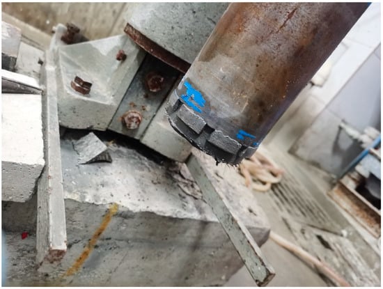
Figure 1.
UHPC cylindrical specimen for dynamic test.
2.3.2. Preparation of Normal UHPC Specimen
For fiber non-oriented specimens, PVC pipe with a diameter of 75 mm was used as a model, as shown in Figure 2a. The fresh UHPC was prepared, and then it was casted into a PVC pipe. After 28 days of curing, the PVC pipe was cut into cylindrical specimen. Finally, the UHPC specimen was polished into a cylindrical specimen with a diameter of 75 mm and a thickness of 35 mm using a grinding machine to ensure that both ends were smooth and absolutely parallel, as shown in Figure 2b,c.
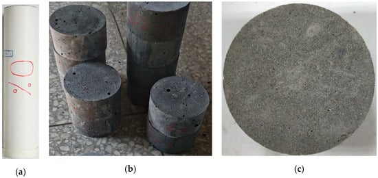
Figure 2.
Preparation of normal UHPC specimen. (a) PVC pipe (b) Cylindrical specimen (c) The specimen after grinding.
3. Dynamic Impact Test Method
The size of the impact test specimen of thet fiber-oriented UHPC was Ø75×35 mm; the specific steps of the impact test were as follows:
(1) In order to reduce the friction effect between the pressure bar and the end face of the specimen, the end faces of the specimen must be smooth enough. After curing to the age, the specimens were cut and polished by a hand self-contained integrated cutting machine and a high-precision grinding machine. Finally, the specimen was polished into a cylindrical specimen with a diameter of 75 mm and a thickness of 35 mm. The roughness at both ends of the specimen was less than 20 μm.
(2) Leveling the impact bar, incident bar, transmission bar, and absorption bar, so that the end faces of the four-rod members were on the same horizontal plane and the end faces were completely fitted. In order to fit the specimen with the incident rod and the transmission rod completely, Vaseline was smeared on the two end faces of the specimen before mounting the specimen, and a waveform shaper was affixed on the incident rod.
(3) Adjusting the impact pressure of the test and starting.
The dynamic impact of UHPC was studied using a split-Hopkinson pressure bar (SHPB). In Figure 3, the SHPB experimental device includes a power drive system, a support system, a rod system, a signal-measuring system, and a damping-absorption system. As shown in the figure, the driving system was composed of a high-pressure nitrogen cylinder and an air gun. The rod system includes a bullet, incident rod, transmission rod, and suction rod. The measuring system includes a velodrometer and a strain collection system. The speed-measuring system consists of a pair of equal light sources and a speed-measuring circuit. By testing the time of the bullet passing through two parallel light sources, the speed of the bullet was calculated according to the distance between the two light sources. The data acquisition system consisted of a strain gauge, super-dynamic strain gauge, and transient waveform memory. Its function was to convert the strain signal in the rod into electrical signal storage for the calculation of the stress–strain curve.
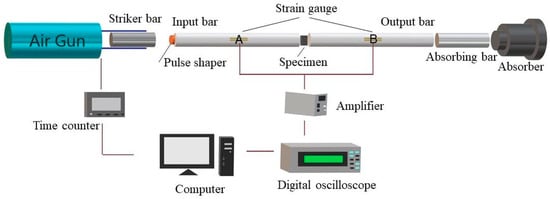
Figure 3.
Schematic diagram of SHPB device.
The working principle of the SHPB device can be described as follows: During the test, the sample was sandwiched between the incident bar and the transmission bar, and the bullet was driven by high-pressure gas. The bullet struck the incident bar at a certain speed V0 and generated a pulse εI(t) in the incident bar, which was called the incident wave. The incident wave propagated to the sample along the incident bar and was recorded when it passed through strain gauge A. When the incident wave propagated to the sample location, it pushed the sample to begin to deform. A reverse stress pulse was generated in the input rod, called the reflected wave εR(t), which is recorded when it reaches strain gauge A. The other part of the pulse propagates through the sample into the transmission rod, known as the transmitted wave εT(t), which was recorded when passing through the strain gauge B. The stress–strain curve under impact loa7d can be obtained by processing the three pulse signal waves. The strain rate, average strain, and average stress were calculated according to Equations (1)–(3):
where υe is the longitudinal wave velocity of the rod; Ee and Ae represent the elastic modulus and cross-sectional area of the rod, respectively; and Ls and As are the length and cross-sectional area of the specimens, respectively. εI(t), εR(t), and εT(t) represent the incident wave signal, reflected wave signal, and transmitted wave signal measured by the strain gauges, respectively.
4. Result and Discussion
4.1. Single Dynamic Impact Test
4.1.1. Stress–Strain Curve
The strain rate ranging from 30 s−1–190 s−1 was included on the normal UHPC specimen. Resulting from calculations according to Equations (2) and (3), the stress–strain curves of the specimens with different fiber contents are shown in Figure 4, and the results included are summarized in Table 3 and Table 4. It could be observed that that the stress–strain curves were composed of rising parts, gentle parts, and falling parts. The rising part can be approximated as a straight line, indicating that the relationship between stress and strain is linear. After the peak stress is reached, the curve entered the gentle part. It is notable that the strain interval of the stress–strain curve changed significantly. The rising part, the gentle part, and the falling part of the stress–strain curve of the U-SF0 can be observed from 0–0.003, 0.003–0.007, and 0.007–0.017, respectively. When steel fibers were added, the range of the strain increased accordingly. The range of the strain reflected the deformability of the specimens. Therefore, the addition of steel fiber significantly improved the deformation ability of UHPC.
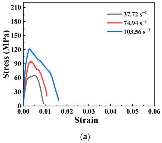
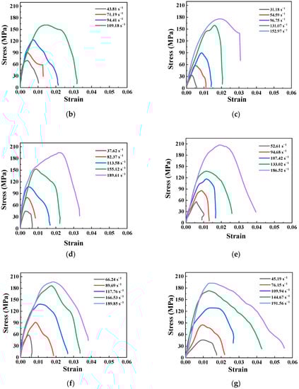
Figure 4.
Impact compression stress–strain curves of UHPC: (a) U-SF0; (b) U-SF2; (c) D-SF2; (d) U-SF4; (e) D-SF4; (f) U-SF6; and (g) D-SF6.
Table 3.
Influence of non-oriented fiber content on impact compression performance.
Table 4.
Influence of directional fiber content on impact compression performance.
However, whether the fiber was oriented or not had little effect on the increase of the peak stress in the single-impact compression test, and only had a significant effect on the increase of the maximum strain. It can be seen from Table 3 that the specimens with 6% steel fiber content showed the highest stress peak and had the best impact resistance. When the incident bar speed was 12.1 m/s, the strain rate of the SF6F specimen was 189.85 s−1, and the peak stress reached 196.4 MPa. The strain rate of the SF6D specimen was 191.56 s−1, and the peak stress reaches 192.5 MPa. However, the contribution of fiber in this aspect covered up the problem of reducing the compactness of the matrix, which was caused by the high fiber content. Younghoon Bae [] also conducted impact tests on UHPC with different fiber contents. He found that with the increase of the steel fiber content, the number of multiple cracks increased. The results showed that under a heavy load and impact load, the higher the steel fiber content, the stronger the energy absorption capacity of the sleeper. The fracture propagation pattern also highlighted that with the increase of the degree of fiber reinforced, the crack resistance of the same width of crack will also increase.
4.1.2. Dynamic Stress and Dynamic Increase Factor
As can be seen from the stress–strain curves in Figure 4, the greater the strain rate of the fiber-reinforced UHPC, the greater the peak stress. In the D-SF6 curve shown in Figure 4, the peak stress was 46 MPa when the strain rate was 45.19 s−1. When the strain rate increased to 76.15 s−1, the peak stress also increased to 84.8 MPa. With the further increase of the strain rate from 109.94s−1 to 144.67 s−1 to 191.56 s−1, the stress peak also increased to 128.8 MPa, 172.7 MPa, and 192.5 MPa. This is the strain rate effect, which may be caused by the Stefan effect caused by the free water in the concrete material [].
Modern architecture may be under various loads; it is simple to foresee that its static load by its structural static mechanics performance was not comprehensive. The accurate calculation and simulation of the structure may bear the dynamic impact load, which can be more scientific. To analyze the dynamic effects of UHPC, the dynamic increase factor (DIF) was introduced. The DIF refers to the ratio of the dynamic compressive strength to the quasi-static compressive strength, which can be calculated according to Equation (4).
where Pdcs and Pscs represent the dynamic compressive strength and static compressive strength, respectively. It was used to characterize changes in strength due to changes in the load strain rate. The effects of different steel fiber contents and fiber orientation on the strain rate effect are summarized in Figure 5.
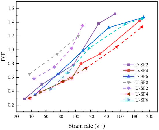
Figure 5.
The effect of fiber content on strain rate.
In the impact compression test, the strain rate and DIF of the specimens with different fiber contents showed a positive linear correlation, and gradually increased with the increase of the strain rate. In Figure 5, compared with U-SF6, the D-SF6 curve showed a stronger sensitivity to the dynamic enhancement factor. It showed that in multiple working conditions, with 6% content as the first, fiber-reinforced (fiber-oriented) UHPC can obtain greater strength enhancement under the condition of a higher strain rate.
4.1.3. Peak Strain
The average peak strain of specimens with different fiber contents in the impact compression test is shown in Figure 6. As mentioned above, fiber orientation has little influence on the dynamic peak impact strength of the specimen. However, it can be seen from Figure 7 that its influence on the peak strain was obvious. When the fiber content was 2%, the average peak strain of the fiber-oriented specimen increased by 35.8% compared with the non-oriented specimen. When the fiber content is 4%, the average peak strain of the fiber-oriented specimen was increased by 37.2%.
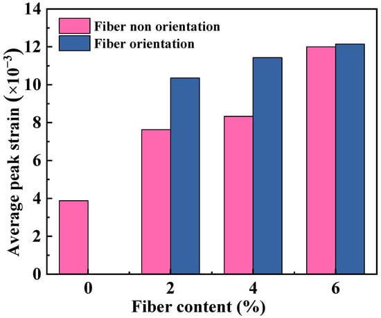
Figure 6.
Effect of fiber content and orientation on peak strain.
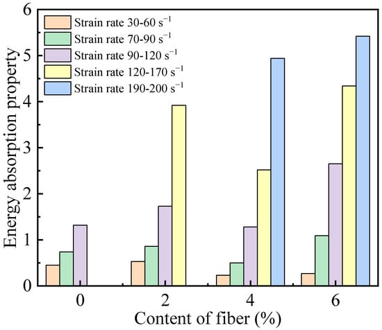
Figure 7.
Influence of fiber content on energy absorption property in dynamic impact test (fiber non-oriented).
4.1.4. Energy Absorption Performance
The energy absorption performance of the material under impact can be obtained by integrating the area of the stress–strain curve. Figure 7 shows the influence of fiber content on the energy absorption performance at different strain rates. It can be seen that the influence of fiber content on the energy absorption performance was extremely significant. In the unmixed fiber group, the energy absorption performance of the specimen was extremely low, almost negligible, showing the typical brittle characteristics of concrete. After fiber incorporation, especially at a high strain rate, the energy absorption performance was significantly improved. When the fiber content was 2%, the energy absorption performance was improved by 31.06% at the same strain rate. When the strain rate continued to increase, the energy absorption performance increased by 196.97%. When the content of fiber was increased to 4%, the maximum energy absorption performance of the specimen increased by 26.02% compared with 2% at a high strain rate. As the dosage continued to increase, the improvement effect on the energy absorption performance was not obvious, and the highest dosage was only 9.72% higher than that of U-SF4.
From Figure 8, the variation of energy absorption in the fiber-oriented group was similar to that in the non-oriented group, but the overall energy absorption effect was improved on the basis of the non-oriented group. Under the condition of the same fiber content, the maximum energy absorption effect of the directional distributed fiber specimens increased by 10.2%, 10.73%, and −11.52%, respectively. Obviously, the energy absorption performance of the specimen decreased slightly compared with that of the non-oriented block at the highest fiber content, and the reasons were analyzed as follows: (1) In order to maintain the orientation of the fiber as much as possible, steps such as tamping and vibrating were skipped in the orientation pouring process of the fiber. A large number of holes and bubbles in the slurry were not effectively discharged, and the stability of the internal structure was slightly worse than that of the specimen with complete vibration. (2) In the case of a large amount of fiber, the disoriented fibers may have a better absorption effect on the bearing of dynamic impact loads.
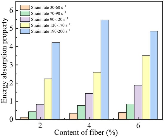
Figure 8.
Influence of fiber content on energy absorption property in dynamic impact test (fiber-oriented).
4.1.5. Failure Pattern
Figure 9 shows the failure state of fiber non-oriented specimens under a dynamic impact test with three fiber contents. When 2% fiber was added, the specimen can maintain its integrity under the conditions of a low strain rate and lower strain rate. However, when the impact velocity increased and the high strain rate reached 109.18 s−1, the specimen could not bear it and fell apart. When the fiber content was 4%, the ability of the specimen to maintain its integrity after the impact compression load was significantly improved; at low strain rates, only a small number of concrete fragments in the appearance of the corners were peeled off. At the higher strain rate of 155.12 s−1, only one corner of the specimen was broken, and the main crack appeared in the middle of the block, but it did not break completely. It only completely broke when the bullet hit at a higher velocity. At the same time, the increase of fiber content greatly improved the ability of the specimen to maintain its integrity after the impact load. When the fiber content was increased to 6%, the specimen still maintained great integrity even at a high strain rate.
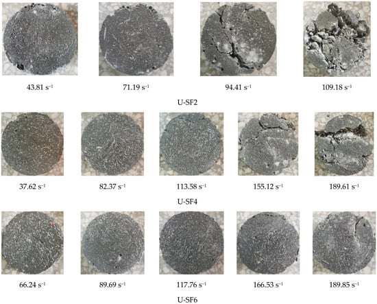
Figure 9.
Failure pattern of fiber in non-oriented UHPC impact compression test.
Fiber-oriented specimens had unique appearance characteristics in the form of impact compression failure, as shown in Figure 10. After undergoing impact compression loads, all cracks were in the same direction as the fiber center line. The D-SF2 specimen showed the clearest failure mode at the strain rate of 152.97 s−1. The two main fracture surfaces are completely consistent with the fiber orientation, and several other fracture branches also maintained a small angle. This phenomenon was mainly because, in the direction of the fibers, even if the concrete produces great stress and transverse expansion, there were still a lot of fibers between the specimens to provide a bridging effect, which inhibits the development of cracks in the specimens. However, in the direction perpendicular to the fiber, the fiber can provide very little bridging force to the matrix. At the same time, the cracks in the fiber direction were also distributed in the vertical direction, so there was a large deformation in the vertical direction, resulting in parallel cracks or z-shaped cracks.
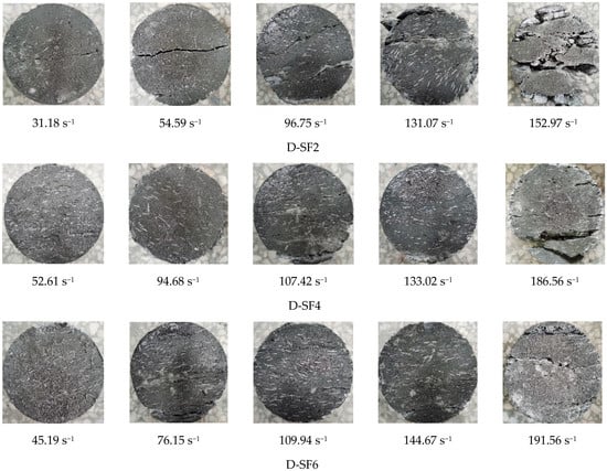
Figure 10.
Failure pattern of fiber-oriented UHPC impact compression test.
4.2. Multiple Dynamic Impact Test
The stress–strain curve of U-SF2 in the impact compression test is shown in Figure 11, and the failure modes are analyzed in Figure 12. From Figure 11, the stress peak decreases with the increase of the number of shocks. In the course of the multiple-impact compression tests, each impact load damaged the specimen to some extent. In Figure 12 1st, although the specimen did not show any damage and visible deformation in its appearance, a micro-crack had started to develop from the inside of the specimen. In addition, in the first impact, a small number of cracks were generated. With the continuous application of impact load, the cracks further developed and the damage gradually intensified. From Figure 12 2nd and 3rd, it can be seen that the cracks inside the specimen had developed to a certain extent. The cracks were connected and extended until they reach the outer surface, and visible deformation was observed in the specimen. After the fourth impact, obvious cracks appeared in the specimen. Six shocks later, the specimen was seriously damaged, the peak of the impact stress decreased significantly, and the specimen soon lost its bearing capacity and became fragmented. In the above process, the fibers showed a good toughening effect. Especially when the fiber doping was increased to 4% and 6%, the development of cracks inside the specimen usually required more than five impact loads before they developed into mutual penetration and were visible on the outside.
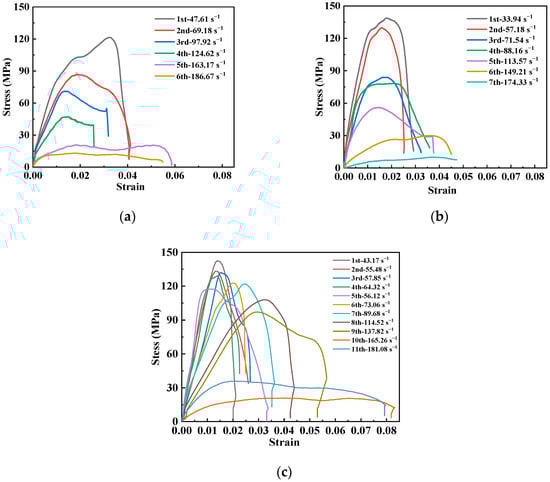
Figure 11.
Stress–strain curves of non-oriented multiple-impact compression of fibers: (a) U-SF2; (b) U-SF4; and (c) U-SF6.
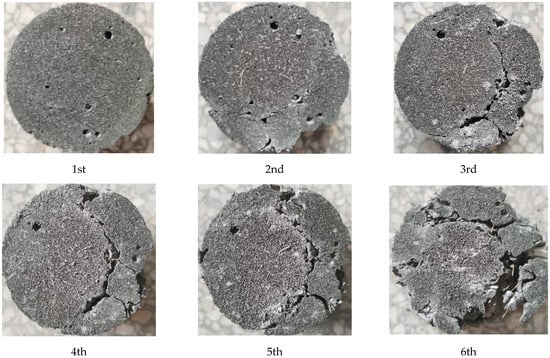
Figure 12.
Failure pattern of fiber non-oriented multiple-impact compression specimens.
The stress–strain curve of D-SF2 in the impact compression test was shown in Figure 13, and the comparison of the failure morphologies of directional fibers was shown in Figure 14. The peak stress, resistance to multiple-impact compression, and dynamic energy absorption properties were more obviously improved at 2% fiber doping. However, the enhancement of dynamic impact mechanical properties by high fiber doping was not obvious. The reason was that the ultimate anisotropy was sought in fiber-oriented distributed UHPC. It is for the sake of the more prominent load in one direction, at the expense of the mechanical properties in other directions, in order to achieve the best use and more efficient effect. For example, the stress state of the flexural beam can be basically determined, and its damage area was generally the span of the beam, the bottom tensile part; therefore, by improving the fiber-bridging capacity of this part, it is possible to achieve an overall performance improvement effect. The contribution of oriented fibers to the improvement of the impact resistance compression performance was smaller.
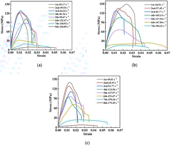
Figure 13.
Fiber-oriented UHPC multiple-impact compression stress–strain curves: (a) D-SF2; (b) D-SF4; and (c) D-SF6.
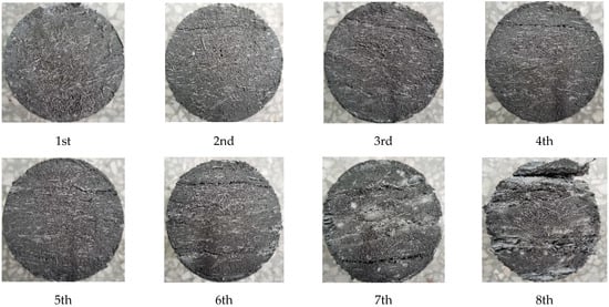
Figure 14.
Failure mode of fiber-oriented multiple-impact compression specimens.
5. Conclusions
(1) Whether the fiber was oriented or not had little effect on the increase of the peak strength in the single-impact compression test, but had a significant effect on the increase of the maximum strain. With the increase of fiber content, the peak stress, energy absorption, and multiple-impact compression resistance of the specimen had been greatly improved.
(2) All specimens showed an obvious strain rate effect. When the fiber content was 6%, fiber-oriented UHPC can obtain greater strength enhancement under the condition of a higher strain rate.
(3) Fiber orientation had no significant effect on the performance of the dynamic impact compression test. It mainly provided a great improvement of the bearing capacity in a certain preset direction, but did not enhance or even sacrifice the bearing capacity in other directions.
Author Contributions
Conceptualization, Y.W.; methodology, Y.W. and L.F.; software, Y.W., S.L. and Y.F.; validation, S.L. and Y.F.; data curation, K.S.; writing—original draft preparation, K.S.; writing—review and editing, K.S.; supervision, L.F. All authors have read and agreed to the published version of the manuscript.
Funding
This research was funded by [Special Fund for Basic Scientific Research Operations of Central Public Welfare Scientific Research Institutes] grant number [Y421004].
Institutional Review Board Statement
Not applicable.
Informed Consent Statement
Not applicable.
Data Availability Statement
Some or all data, models, or code that support the findings of this study are available from the corresponding author upon reasonable request.
Conflicts of Interest
The authors declare no conflict of interest.
References
- Ha, N.S.; Marundrury, S.S.; Pham, T.M.; Pournasiri, E.; Shi, F.; Hao, H. Effect of Grounded Blast Furnace Slag and Rice Husk Ash On Performance of Ultra-High-Performance Concrete (Uhpc) Subjected to Impact Loading. Constr. Build. Mater. 2022, 329, 127213. [Google Scholar] [CrossRef]
- Liu, J.; Wu, C.; Li, J.; Liu, Z.; Xu, S.; Liu, K.; Su, Y.; Fang, J.; Chen, G. Projectile Impact Resistance of Fibre-Reinforced Geopolymer-Based Ultra-High Performance Concrete (G-Uhpc). Constr. Build. Mater. 2021, 290, 123189. [Google Scholar] [CrossRef]
- Habel, K.; Viviani, M.; Denarié, E.; Brühwiler, E. Development of the Mechanical Properties of an Ultra-High Performance Fiber Reinforced Concrete (Uhpfrc). Cem. Concr. Res. 2006, 36, 1362–1370. [Google Scholar] [CrossRef]
- Tafraoui, A.; Escadeillas, G.; Vidal, T. Durability of the Ultra High Performances Concrete Containing Metakaolin. Constr. Build. Mater. 2016, 112, 980–987. [Google Scholar] [CrossRef]
- Lai, D.; Demartino, C.; Xiao, Y. High-Strain Rate Compressive Behavior of Fiber-Reinforced Rubberized Concrete. Constr. Build. Mater. 2022, 319, 125739. [Google Scholar] [CrossRef]
- Akça, K.R.; İpek, M. Effect of Different Fiber Combinations and Optimisation of an Ultra-High Performance Concrete (Uhpc) Mix Applicable in Structural Elements. Constr. Build. Mater. 2022, 315, 125777. [Google Scholar] [CrossRef]
- Ragalwar, K.; Heard, W.F.; Williams, B.A.; Kumar, D.; Ranade, R. On Enhancing the Mechanical Behavior of Ultra-High Performance Concrete through Multi-Scale Fiber Reinforcement. Cem. Concr. Compos. 2020, 105, 103422. [Google Scholar] [CrossRef]
- Chun, B.; Yoo, D. Hybrid Effect of Macro and Micro Steel Fibers On the Pullout and Tensile Behaviors of Ultra-High-Performance Concrete. Compos. Part B Eng. 2019, 162, 344–360. [Google Scholar] [CrossRef]
- Park, S.H.; Kim, D.J.; Ryu, G.S.; Koh, K.T. Tensile Behavior of Ultra High Performance Hybrid Fiber Reinforced Concrete. Cem. Concr. Compos. 2012, 34, 172–184. [Google Scholar] [CrossRef]
- Emamian, S.A.; Eskandari-Naddaf, H. Genetic Programming Based Formulation for Compressive and Flexural Strength of Cement Mortar Containing Nano and Micro Silica After Freeze and Thaw Cycles. Constr. Build. Mater. 2020, 241, 118027. [Google Scholar] [CrossRef]
- Kooshkaki, A.; Eskandari-Naddaf, H. Effect of Porosity On Predicting Compressive and Flexural Strength of Cement Mortar Containing Micro and Nano-Silica by Multi-Objective Ann Modeling. Constr. Build. Mater. 2019, 212, 176–191. [Google Scholar] [CrossRef]
- Thongbai-on, N.; Banomyong, D. Flexural Strengths and Porosities of Coated Or Uncoated, High Powder-Liquid and Resin-Modified Glass Ionomer Cements. J. Dental Sci. 2020, 15, 433–436. [Google Scholar] [CrossRef]
- Zhou, B.; Uchida, Y. Relationship Between Fiber Orientation/Distribution and Post-Cracking Behaviour in Ultra-High-Performance Fiber-Reinforced Concrete (Uhpfrc). Cem. Concr. Compos. 2017, 83, 66–75. [Google Scholar] [CrossRef]
- Jafarzadeh, H.; Nematzadeh, M. Evaluation of Post-Heating Flexural Behavior of Steel Fiber-Reinforced High-Strength Concrete Beams Reinforced with Frp Bars: Experimental and Analytical Results. Eng. Struct. 2020, 225, 111292. [Google Scholar] [CrossRef]
- Raju, R.A.; Lim, S.; Akiyama, M.; Kageyama, T. Effects of Concrete Flow On the Distribution and Orientation of Fibers and Flexural Behavior of Steel Fiber-Reinforced Self-Compacting Concrete Beams. Constr. Build. Mater. 2020, 262, 119963. [Google Scholar] [CrossRef]
- Ferrara, L.; Ozyurt, N.; di Prisco, M. High Mechanical Performance of Fibre Reinforced Cementitious Composites: The Role of “Casting-Flow Induced” Fibre Orientation. Mater. Struct. 2011, 44, 109–128. [Google Scholar] [CrossRef]
- Kang, M.; Yoo, D.; Gupta, R. Machine Learning-Based Prediction for Compressive and Flexural Strengths of Steel Fiber-Reinforced Concrete. Constr. Build. Mater. 2021, 266, 121117. [Google Scholar] [CrossRef]
- Hambach, M.; Möller, H.; Neumann, T.; Volkmer, D. Portland Cement Paste with Aligned Carbon Fibers Exhibiting Exceptionally High Flexural Strength (>100 Mpa). Cem. Concr. Res. 2016, 89, 80–86. [Google Scholar] [CrossRef]
- Yoo, D.; Banthia, N.; Kang, S.; Yoon, Y. Effect of Fiber Orientation On the Rate-Dependent Flexural Behavior of Ultra-High-Performance Fiber-Reinforced Concrete. Compos. Struct. 2016, 157, 62–70. [Google Scholar]
- Huang, H.; Gao, X.; Li, L.; Wang, H. Improvement Effect of Steel Fiber Orientation Control On Mechanical Performance of Uhpc. Constr. Build. Mater. 2018, 188, 709–721. [Google Scholar] [CrossRef]
- Zhang, Y.; Zhu, Y.; Qu, S.; Kumar, A.; Shao, X. Improvement of Flexural and Tensile Strength of Layered-Casting Uhpc with Aligned Steel Fibers. Constr. Build. Mater. 2020, 251, 118893. [Google Scholar] [CrossRef]
- Bae, Y.; Pyo, S. Effect of Steel Fiber Content On Structural and Electrical Properties of Ultra High Performance Concrete (Uhpc) Sleepers. Eng. Struct. 2020, 222, 111131. [Google Scholar] [CrossRef]
Disclaimer/Publisher’s Note: The statements, opinions and data contained in all publications are solely those of the individual author(s) and contributor(s) and not of MDPI and/or the editor(s). MDPI and/or the editor(s) disclaim responsibility for any injury to people or property resulting from any ideas, methods, instructions or products referred to in the content. |
© 2023 by the authors. Licensee MDPI, Basel, Switzerland. This article is an open access article distributed under the terms and conditions of the Creative Commons Attribution (CC BY) license (https://creativecommons.org/licenses/by/4.0/).