Article

Behavior of Barrier Wall under Hydrogen Storage Tank Explosion with Simulation and TNT Equivalent Weight Method

Department of Civil Engineering, Kangwon National University, 346 Jungang-ro, Samcheok 25913, Republic of Korea
*
Authors to whom correspondence should be addressed.
Appl. Sci. 2023, 13(6), 3744; https://doi.org/10.3390/app13063744
Submission received: 3 February 2023 / Revised: 11 March 2023 / Accepted: 13 March 2023 / Published: 15 March 2023
(This article belongs to the Special Issue Blast Loading and Blast Effect on Structures)

Abstract

:
Hydrogen gas storage place has been increasing daily because of its consumption. Hydrogen gas is a dream fuel of the future with many social, economic and environmental benefits to its credit. However, many hydrogen storage tanks exploded accidentally and significantly lost the economy, infrastructure, and living beings. In this study, a protection wall under a worst-case scenario explosion of a hydrogen gas tank was analyzed with commercial software LS-DYNA. TNT equivalent method was used to calculate the weight of TNT for Hydrogen. Reinforced concrete and composite protection wall under TNT explosion was analyzed with a different distance of TNT. The initial dimension of the reinforced concrete protection wall was taken from the Korea gas safety code book (KGS FP217) and studied the various condition. H-beam was used to make the composite protection wall. Arbitrary-Lagrangian-Eulerian (ALE) simulation from LS-DYNA and ConWep pressure had a good agreement. Used of the composite structure had a minimum displacement than a normal reinforced concrete protection wall. During the worst-case scenario explosion of a hydrogen gas 300 kg storage tank, the minimum distance between the hydrogen gas tank storage and protection wall should be 3.6 m.

1. Introduction

In recent years, the world has been dealing with the problem of an energy crisis due to the depletion of resources and increased environmental problems [1]. Hydrogen gas is an important energy carrier and a potential alternative clean energy fuel with a significant stake in the global fuel market. Hydrogen gas will be a crucial contribution to sustainable development because, in the future, it may be produced in virtually unlimited quantities using renewable energy sources. The major future markets for hydrogen depend upon four factors: the future cost of the hydrogen, the rate of advances of various technologies that use hydrogen, the cost of competing energy systems, and potential long-term restrictions on green gases. Hydrogen holds the promise as a dream fuel of the future with many social, economic and environmental benefits to its credit. Because of such benefits, the consumption of hydrogen gas is increasing year by year. South Korea is pursuing a hydrogen economy for economic growth and industrial competitiveness more than for climate change objectives. In particular, South Korea sees hydrogen as a potential driver of economic growth worth $43 billion and 420,000 new jobs [2]. Although it has many benefits, the accident of hydrogen gas tank explosion can cause massive infrastructure damage and loss of living beings. Hydrogen used in fuel cells is a very flammable gas and can cause fires and explosions if it is not handled correctly. The lower and upper limits for combustion volume percentage in the air of hydrogen gas are 4% and 75%, respectively [3]. Gas explosion accidents frequently happen in South Korea and foreign countries. The blast load generated by hydrogen gas tank explosion on structures can be hazardous; damages and failure are expected, with severe threats to structural safety and human life. A devastating hydrogen tank exploded at Gangwon Technopark in Gangneung, South Korea, on May of 2019, a tanker truck explosion at the Air Product and Chemical facility in Santa Clara, CA, on June 2019, and an explosion occurred at the hydrogen production plant in Texas City on June 2020 were the few accidents occurred in past years [4]. Good standards and best practices are indispensable for planning and installing a large-scale production and distribution infrastructure in urban areas [5].
Safe practices in the production, storage, distribution, and use of hydrogen are essential for the widespread acceptance of hydrogen technologies. Hydrogen gas is an aspect of critical infrastructure that requires attention regarding fire and explosion protection. Hydrogen vehicles have partnered with major gas distributors to add hydrogen filling capacity at a regular old gas station, representing a great benefit to getting fuel but bringing the hazard into the public domain. If hydrogen gas were to leak at a hydrogen refueling station, the probability of ignition and possible subsequent pressure loads on the surrounding structures would be high. Therefore, it is necessary to design to protect against the potential for severe damage to the protection wall and serious harm to people in the region of an accident. Residential areas need to be protected from the spread of fire and explosions, and protection walls are a perfect solution to avoid damage and liability to hydrogen gas stations. Reinforced concrete (RC) wall is widely used as a protection wall. Author studied the reinforced cement concrete wall panels under TNT blast load with 50 and 100 kg. Steel strips improved the blast resistance up to 100 kg of TNT [6]. The reinforcement ratio in reinforced concrete has influence on the survivability of RC slabs when subjected to blast loading [7]. The researcher team conducted the hydrogen explosion test with a barrier wall and measured blast pressure propagation and structural behavior of the barrier wall [8]. The blast performance of steel-reinforced concrete (RC) beams experimentally and analytically investigated. It was concluded from the Liu et al. study that RC beams only suffer flexural deformation. With the decrease in the scaled distance, damage mode changes from a few cracks on the surface to spallation on the back surface. In addition, crushing on the top surface occurred. Besides, RC beams suffer more with the increased charge mass under the same scaled distance [9]. The response of reinforced concrete panels externally reinforced with steel strips and concluded that in addition to existing strengthening techniques, steel strips are amongst the most feasible techniques for strengthening existing structures under blast load. Researchers studied the dynamic response of typical wide-flange steel beams with an experiment under blast load, and the effects of charge size and stand-off distance on their behavior were investigated by measuring their response using various measuring devices. None of the beams experienced local buckling or another type of local failure; instead, they all exhibited a ductile response under blast loading [10]. Similarly, other research has been done by researchers under blast load for composite structure can be found [10,11,12,13,14,15].

1.1. Objectives

In this study, the dimension of the reinforced concrete protection wall was taken from the Korea gas safety code book [16], and various numerical simulation analysis was considered. The primary purpose of this study is to compare a reinforced concrete and composite structure protection wall for hydrogen gas storage stations to save from serious harm to people in the region of the accident and residential areas under explosion. In the code book, minimum height and foundation dimensions are provided but the length of the wall is missing. The code book does not explain the distance between the hydrogen gas tank and the protection wall. Researcher studied the prismatic 5.27 m3 volume that contained 30% hydrogen and 70% air with a thickness of the protection wall 0.15 m, and the distance of the hydrogen gas prismatic was 2 m and 4 m. Even though the volume of the prismatic is 5.27 m3, and the distance is 2 m and 4 m, cracks formed after the explosion on the protection barrier [8]. If the storage tank volume increases, the protection wall gets more damage, and concrete fragmentation reaches a far distance. In KGS FP217, the minimum thickness required for the protection wall is 0.12 m. So, it is necessary to study the protection wall under hydrogen explosion through numerical simulation. Figure 1a shows the hydrogen tank explosion that occurred in Gangneung, South Korea, on May 2019. There was no secondary fire, and the detonation pressure merely caused the damage, but within a 15-m distance from the hydrogen tank, the structure beam of the building was damaged, and most of the windows of the 5-story building, which is about 100 m away and faced to the hydrogen tank, are all crushed. The equivalent TNT is estimated to be about 50 kg [17]. Figure 1b shows the site visit at the hydrogen station at Samcheok, South Korea. The thickness of the reinforced concrete is 0.35 m in Figure 1b, but the distance between the hydrogen gas trailer and the protection wall is 1.53 m. The distance between the protection wall and hydrogen gas storage follows the International Fire Code (IFC) 2009 (States, 2007) [18]. Figure 1a shows the damage on hydrogen storage site after the explosion of hydrogen storage tank. Figure 1b shows the current practice of barrier wall for hydrogen gas station at samcheok, South Korea during site visit and Table 1 represents the minimum requirement of barriers wall thickness in different countries. It is necessary to understand the minimum requirement of barrier wall as in KGS FP217 is safe or not during hydrogen gas explosion. To understand the damage on protection wall under hydrogen gas explosion worse-case scenario (300 kg of Hydrogen gas) and 30 kg of hydrogen gas explosion was carried out through TNT equivalent method and simulation was done with LS-DYNA. Very limited research has been done on hydrogen gas explosions nearby barrier walls.

1.2. Composite Structure

Composite structures are composed of at least two materials. For example, concrete comprises gravel, sand, and cement. Metal rebar is usually incorporated for strength, so reinforced concrete is helpful in construction. Therefore, reinforced concrete structures are widely used in the construction industry. Reinforced cement concrete (RCC) structures are designed for specific loading. However, these structures face severe loading due to frequent hydrogen explosion accidents. Due to the extensive dynamic loading, reinforced cement concrete structural members fail, and casualties/injuries occur. Therefore, studying composite structures to make protective structures under explosion load is essential. In this study, H-beam was used to make a composite structure because of its strength, rigidity, and greater moment of inertia, H-beam can be used for a span of up to 100 m, and it can be made in any size or height.

1.3. Importance of Study

Production and use of hydrogen gas are increasing year by year. Hydrogen is the most potent means of achieving the zero-carbon goal. South Korea will achieve carbon neutrality by 2050 by replacing coal-fired power generation with renewable sources and internal combustion engine vehicles with hydrogen-powered and battery-based electric vehicles. The Chinese government released the country’s first-ever long-term plan for hydrogen, covering the period of 2021–2035 [20]. The plan laid out a phased approach to developing a domestic hydrogen industry and mastering technologies and manufacturing capabilities while pointing to the country’s carbon peaking and neutrality commitments as overarching drivers. The Japanese government has set ambitious goals for a carbon-neutral future to enhance its energy security. It plans to establish a full-scale international hydrogen supply chain to cut the cost of hydrogen by 2030 [21]. In order to promote the development of a strong domestic market, Germany plans to build its first green hydrogen generation plants with a total capacity of up to five gigawatts (GW) by 2030, including the construction of the offshore and onshore infrastructure needed. Safe practices in the production, storage, distribution, and use of hydrogen are essential for the widespread acceptance of hydrogen technologies. Hydrogen gas is an aspect of critical infrastructure that requires attention regarding fire and explosion protection. If hydrogen gas were to leak at a hydrogen refueling station, the probability of ignition and possible subsequent pressure loads on the surrounding structures would be high. Therefore, it is necessary to design to protect against the potential for severe damage to the protection wall and serious harm to people in the region of an accident. China has the greatest number of hydrogen fuel stations of any country worldwide. As per April 2022, there were 250 operational hydrogen refueling stations in the country. This was followed by japan with 161 and Korea with 141 such stations [22]. Table 2 shows the number of hydrogen fueling stations of different countries and this data is not the worldwide data. Figure 2a shows the cumulative number of hydrogen fueling stations of different countries [23]. Figure represents the number of hydrogen fueling stations in different countries with forecasts up to 2030. It is expected that there will be around 520 hydrogen stations in Korea. Figure 2b shows the hydrogen demand worldwide from the 2019 to 2021, with a forecast for 2030 and it is expected to double by 2030 [24].

2. TNT Equivalent Method

2.1. Composite Structure TNT Equivalent Method for Hydrogen Gas in Liquid Form

A common approach for determining the damage caused by hydrogen explosion consists in estimating the TNT equivalent method. In vapor cloud explosions, the equivalent mass of TNT can be calculated using the expression 1. As hydrocarbons, the most common substance involved in vapor cloud explosion is fairly poor explosives, only a small part of the energy released is used to create the blast wave; different authors have proposed values between 1% to 10%. Although the value of explosion efficiency (η) is probably influenced by the reactivity of the fuel involved and the eventual partial confinement of the cloud, the currently accepted value is 1%. The main features of TNT and vapor cloud explosions are different; TNT is a high-energy density explosive, and vapor clouds are a low-energy-density source. TNT explosions are detonations, while vapor cloud explosions are deflagrations i.e., the shape and the velocity of their respective blast waves are different. Furthermore, it is essential to consider that if another alternative method is used, it will be subject to errors arising from uncertainties regarding the size, shape, and composition of the vapor cloud and the influence of the confinement and congestion of the areas covered by the flammable mixture. Therefore, as the TNT equivalency method is straightforward, it remains widely used [25]. This method is taken from the reference [26], and calculation from expression was of 300 kg [27] of hydrogen tank and worst-case scenario explosion was taken. In the present 4% to 75% hydrogen ratio with air, exploding can occur [26]. For this study, a 75% hydrogen volumetric with air was taken. From the expression 1 the equivalent weight of TNT is 69.7 kg.
M T N T = η M H 2 Q H 2 Q T N T
where,
  • MH2 is mass of the hydrogen gas = 300 kg
  • QH2 is Explosion energy of Hydrogen gas = 142.5 MJ/kg
  • QTNT is explosive energy of TNT = 4.6 MJ/kg
  • η is Explosion efficiency (this value is from 0.01 to 0.1) but for this study 0.01 was taken.
After the validation procedure of the model, author confirm that an explosion efficiency of 0.01 is more representative for high pressure hydrogen cylinders explosion [28].

2.2. Blast Wave Process

An explosion is a sudden process with rapid release of energy. This process last only for few milliseconds and produce a very high pressure and temperature. The blast wave effects of an explosion are in the form of a shock wave composed of a high-pressure shock front which expands outward from the center of the detonation, with the pressure intensity decaying with distance. The wave front impinges a protective structure; the shock pressures will engulf a portion of the structure or the structure as a whole. The distribution and magnitude of the blast loads on the structure depend upon the type of explosive material, the weight of the explosive, the location of the explosion relative to the protective structure, and the interaction of the shock front with the ground or the protective structure itself. Figure 3 shows the pressure and time relation at the free air blast wave. The surrounding ambient pressure P0 increases to a peak pressure at a time of tA, and at a time tA+ to the pressure reduced to ambient pressure which is called positive phase. And this is followed by a negative pressure wave with duration, t0. In Figure 2 is is positive impulse and is is negative impulse.

3. Finite Element Modeling

3.1. Modelling of Protection Barrier Wall

The dimension of the model was taken from the code book to analyze the current practice for the minimum requirement of protection walls during a hydrogen gas explosion. The compressive strength of the concrete was 35 MPa. The height of the TNT from the ground level is 0.55 m. The distance between TNT and the protection wall was 1.6 m to 3.6 m to understand the behavior of the explosion effect on the protection wall under different distances. TNT equivalent method was used to convert the hydrogen gas tank explosion [26,28,29]. The weight of TNT was 69.7 kg at 75% limits for combustions in the air by volume. With the TNT equivalent, it was possible to predict the damage on the protection wall from simulation. The widely used concrete model implemented in LS-DYNA, the Karagozian & Case concrete material model, was used. Later the thickness of the protection wall increase from 0.12 m to 0.16 m and 0.2 m. Figure 4 shows the dimension of the foundation with different wall thickness.
To improve the effect of blast load on the protection wall, H-beam was used as a composite structure. The dimension of the H-beam for wall thickness of 120 mm is breadth = 240 mm, height = 160 mm, thickness = 10 mm. The compressive strength of the concrete was 35 MPa. H-beam was installed at an interval of 2 m. For a 10 m length of protection, all 4 numbers of H-beam can be placed. For the second case, the thickness of the wall was increased from 120 mm to 200 mm to understand the behavior of the barrier wall under hydrogen gas tank explosion, and only the barrier wall was considered for the simulation. Protection walls with a reinforced concrete structure and steel-concrete composite beams were analyzed under blast load. The position of the H-beam is shown in Figure 5. 16 mm of reinforcement was placed inside of protection wall. A detail of reinforcement is shown in Figure 6. The clear cover for the protection wall was 20 mm.

3.2. Material Model from LS-DYNA

3.2.1. Concrete Model

LS-DYNA material library has different material models for concrete. Comparative studies between different models have been widely conducted in the past, and the blast analysis is mainly performed by using the commercial program, and LS_DYNA is widely adopted. Among concrete constitutive models introduced in LS-DYNA, the K&C and CSCM models are plastic-based damage models developed based on plain concrete [30,31,32,33,34]. In this paper, the MAT_72R3 model allows parameters to be automatically generated based on the unconfined compressive strength as the only input parameter. The automatically generated parameters reflect the behavior of a regular concrete material under blast load and thus are employed in the finite element (FE) models. The model was developed by Malvar [30] based upon a plasticity model produced particularly for concrete and can be customized to define the distinct characteristics of concrete. *MAT_ADD_EROSION was assigned to MAT_72R3 for element erosion. The finite element mesh size for this study’s concrete structural part is 20 mm. Table 3 represents the material properties of concrete.

3.2.2. Reinforcement and H-Beam

The behavior of the H-beam was modeled using the material card MAT_JHONSON_COOK, a constitutive model with its complementary damage model [35]. The JC constitutive model parameters, the physical and mechanical properties of steel used to and simulate the H-beam under explosion. Different researchers in previous studies have effectively utilized this material model to predict the material behavior of steel [36,37]. Table 4 shows the JC constitutive model parameter of Steel. The equation of state (EOS) for H-beam, LINEAR_POLYNOMIAL was used with an input of bulk modulus. MAT_PLASTIC_KINEMATIC model was used for reinforcement. The Young modulus and poison ratio of plastic kinematics were 200 GPa and 0.3, respectively.

3.2.3. TNT, Air and Soil

The air domain was modeled with ALE elements with *NULL material, and the TNT explosive was modeled with ALE elements with *MAT_HIGH_EXPLOSIVE_BURN material card available in the LS-DYNA material library. The mesh size for the TNT, air, and soil was 100 mm. The equation of state (EOS) for air and explosive were LINEAR_POLYNOMIAL and JONES_WILKINS_LEE (JWL), respectively. An explosion in the air creates a spherical shock wave that travels outward from the bursting point with diminishing velocity. The soil domain was modeled with ALE elements with *MAT_SOIL_MATERIAL_MODEL_147 material card available in LS-DYNA. Parameters of air, TNT, and soil are shown in Table 5.

3.2.4. Boundary Condition and Mesh

The denotation point of the TNT was at the center of the TNT. The Arbitrary-Lagrangian-Eulerian (ALE) method was used, which is a straightforward modeling strategy for modeling shock wave propagation. The explosive and the air are separately modeled using the ALE formulation with a multi-material option. Appropriate Equations of State (EOS) were assigned to the materials (explosive and air). A HIGH_EXPLOSIVE_BURN model governs the detonation process of the high-explosive material. *CONSTRAINED_LANGRANGE_IN_SOLID was input to coupling ALE and Lagrangian. Similarly, *CONSTRAINED_LANGRANGE_IN_SOLID contact was used between reinforcement, H-beam and concrete. The shock wave travels through the ALE air domain and then impinges the target structure. Lagrangian elements discretize the target structure. The base of the foundation and soil was fixed boundary condition. The bottom of the wall was fixed for the simulation of only a protection wall with different thicknesses. Non-reflective boundary condition was applied to all sides ALE air except the bottom face. The mesh size of the domain air was 100 mm, whereas the mesh size of the protection structure was 20 mm.

3.2.5. Simulation Analysis of Previous Study [39]

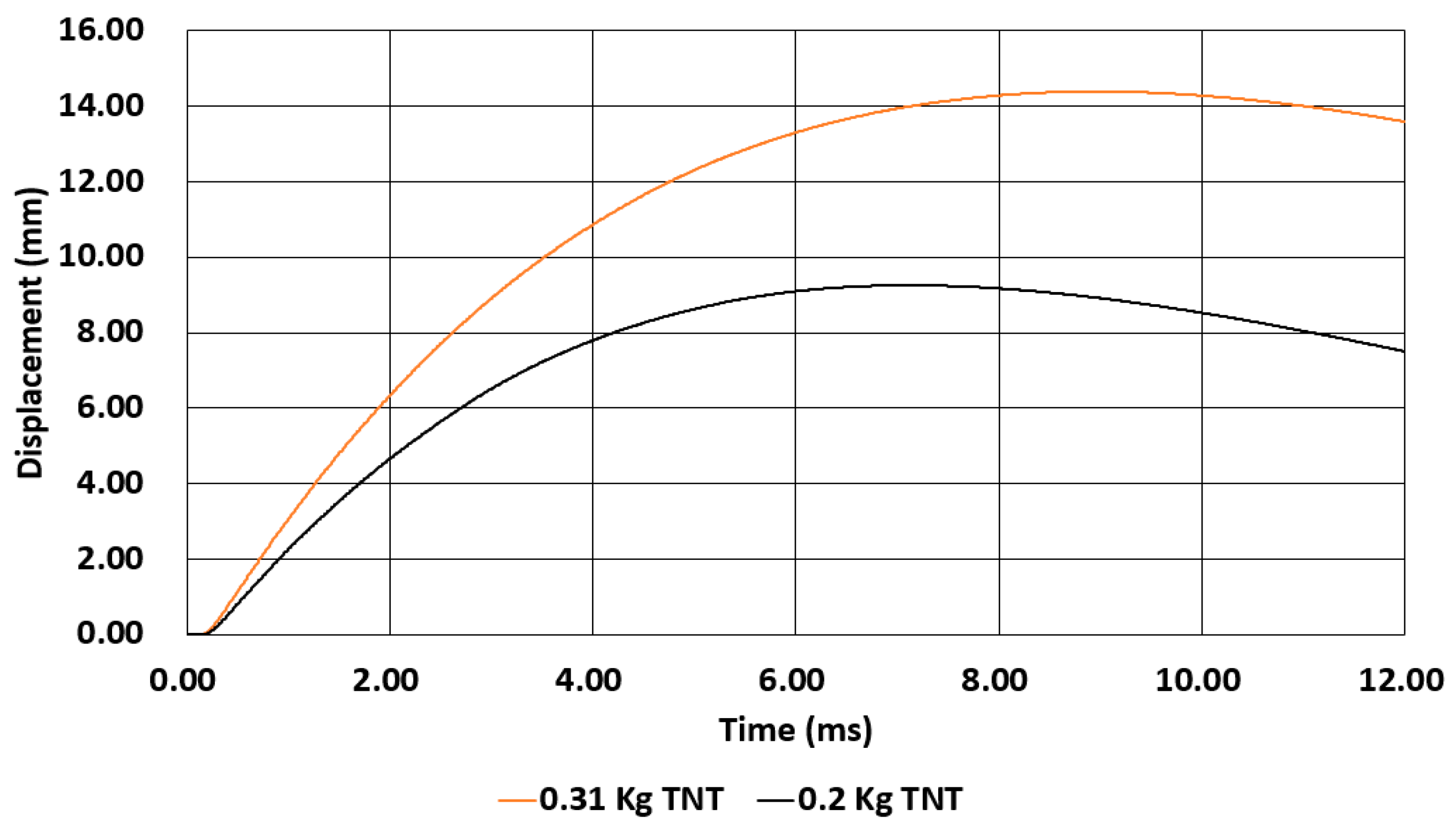
In this section, the experimental study of had been analyzed and the displacement of the slab was compared with experimental study. The 1 m × 1 m square reinforcement slab with 0.04 m thickness was modelled as in experiment and run the simulation. The TNT amount was taken as 0.2 kg and 0.31 kg. The concrete had a cylinder compressive strength of 39.5 MPa. The explosive charges located at a 0.4 m standoff above the slabs. In this study the materials properties and the blast load method was taken as mention above and the simulation displacement was compared with the experimental data. This study had a close displacement result with experimental data as shown in Figure 7 and Table 6. Same blast load was applied for the protection wall under explosion.

4. Results

4.1. Compare between ConWep and ALE Incident Pressure

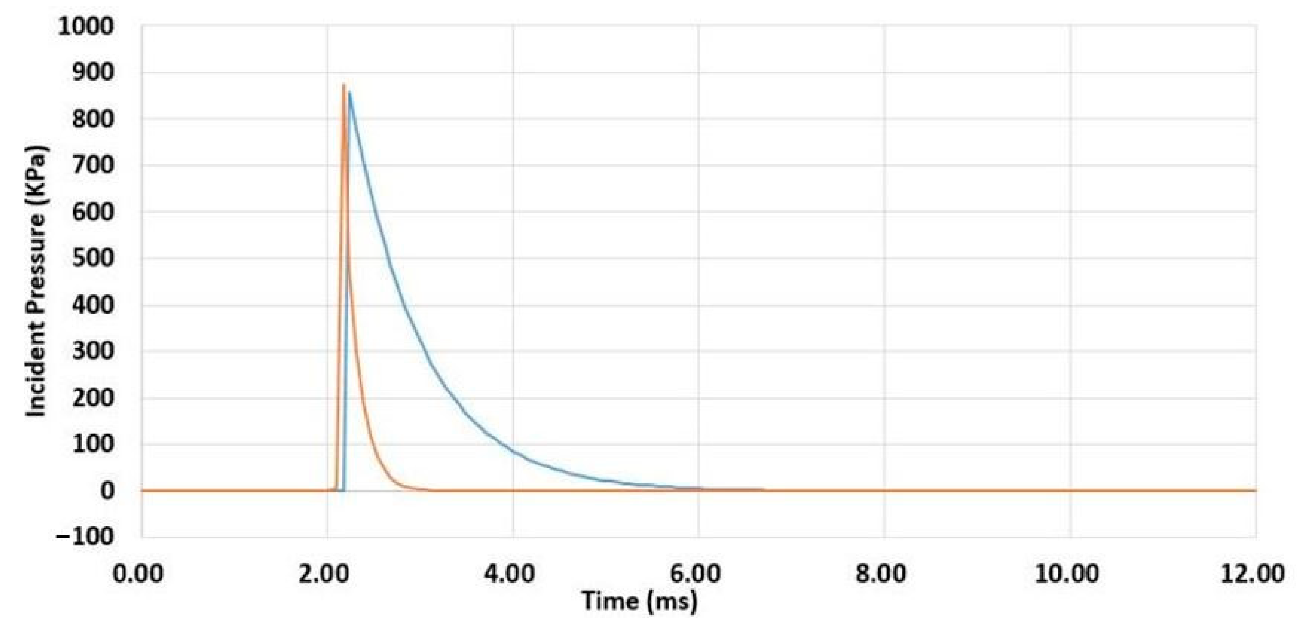
This section compares the spherical free air blast incident pressure between ConWep and ALE and shown in Table 7. ConWep is a collection of conventional weapons effects calculations from the equations and curves of TM 5-855-1, “Fundamentals of Protective Design for Conventional Weapons”. ConWep is based on the empirical model described in the TM5-855 US army handbook [42]. The blast effects of an explosion are in the form of a shock wave composed of a high-pressure shock front which expands outward from the center of the detonation, with the pressure intensity decaying with distance. Figure 8 and Table 6 show the results from the ConWep and ALE simulation. Scale distance for TNT and position of wall are 0.421 m/kg1/3, 0.665 m/kg1/3 and 0.908 m/kg1/3. Scale distance is a distance between protection wall surface and the denotation point of TNT. For ALE simulation, the peak pressure reaches faster, and the blast wave becomes zero within a short time than the ConWep, but the peak pressure is similar. At a distance of 1600 mm the error (%) is high, and for others, the error (%) is less. There is good agreement between the ConWep and ALE simulation methods for incident pressure generated from 69.7 kg of TNT after explosion.

4.2. Displacement Results from Simulation

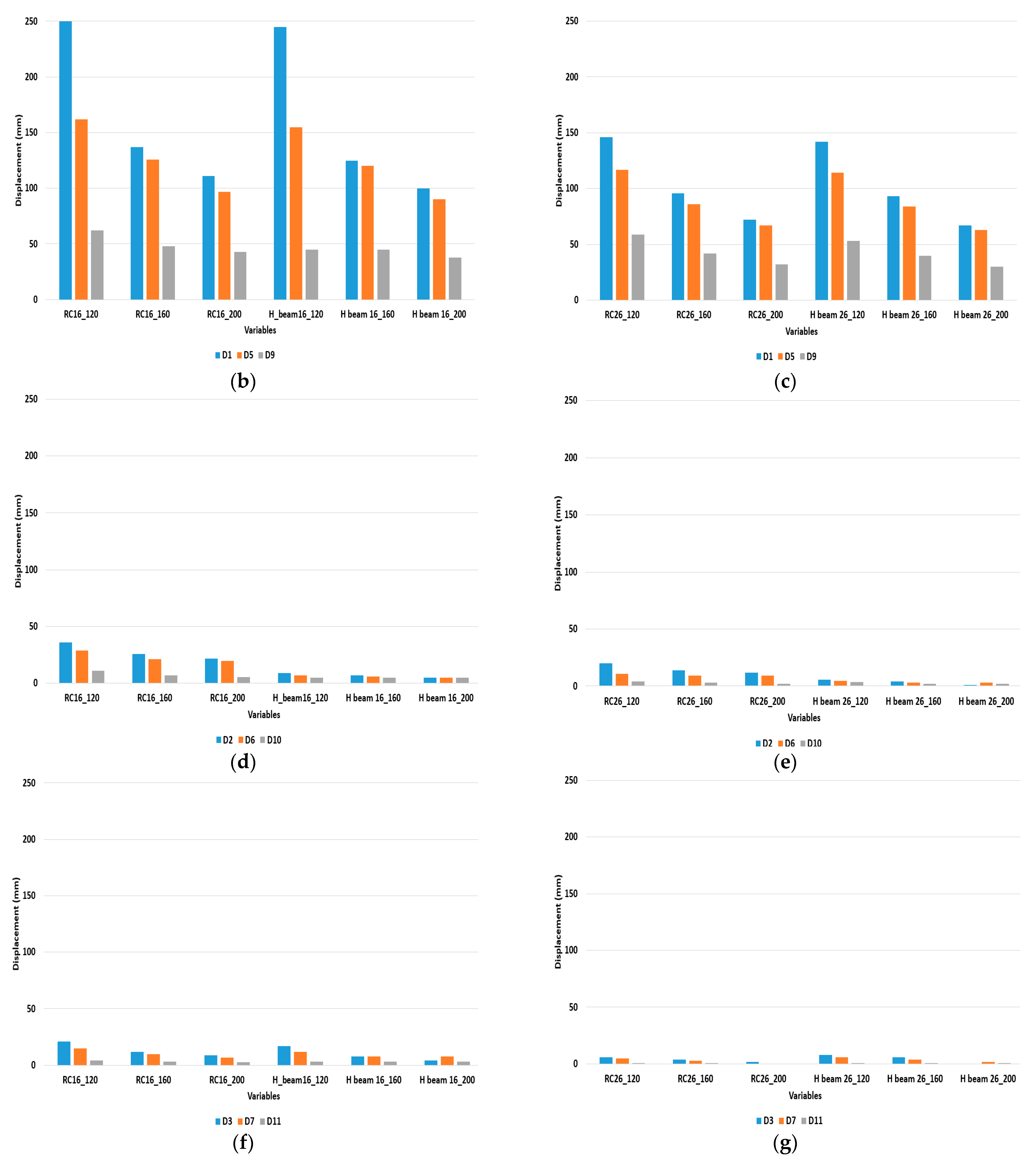
In this simulation the displacement was taken from elements at different position as shown in Figure 9a. The displacement was taken from the back side of the protection wall structure red dot represents the probe position in structure. The total termination time for the simulation is 10 milliseconds. RC16_120 represents the reinforced protection wall and the stand-off distance between the structure and TNT is 1.6 m with the thickness of protection wall is 0.12 m. Similarly, H_beam16_120 represents the composite protection wall structure with 0.12 m thickness. Denotation of variables follows same notations for Figure 9.
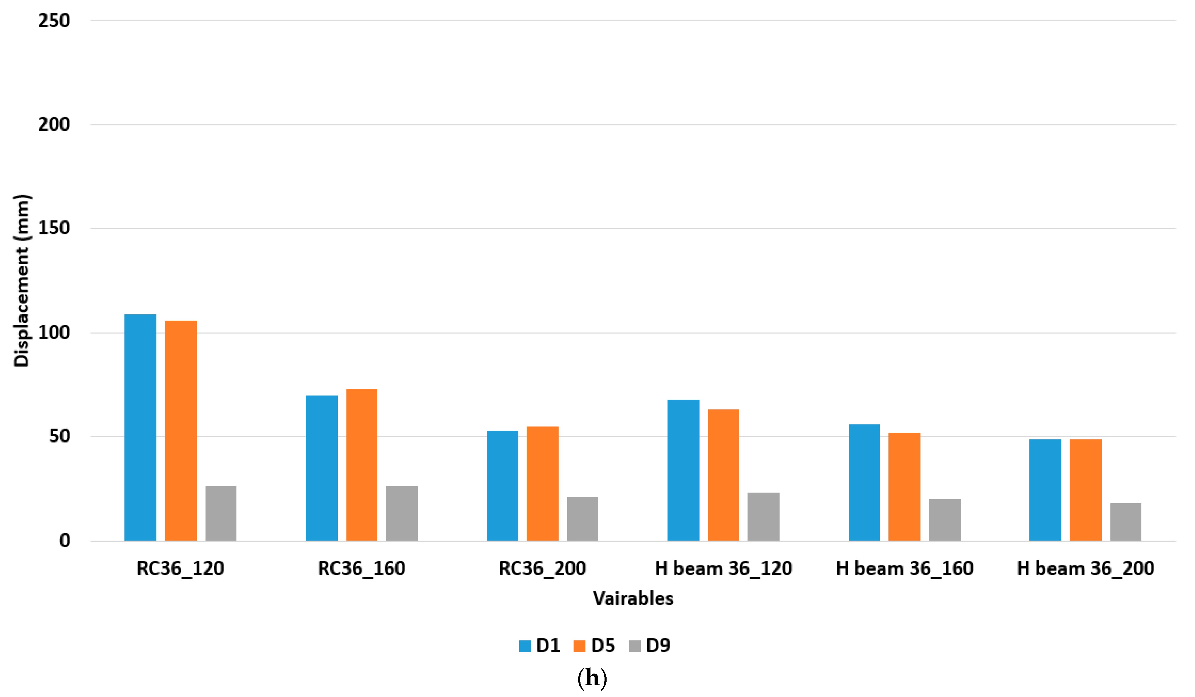
RC_16_120 represents the reinforced protection wall and the stand-off distance between the structure and TNT is 1.6 m with the thickness of protection wall is 0.12 m. Similarly, H_beam16_120 represents the composite protection wall structure with 0.12 m thickness. From Figure 9a, the displacement is higher than the other variables. Installation of H-beam reduced the displacement but the difference is minimum during worse- case scenario. Increasing the thickness of the protection wall reduce the displacement of elements after explosion. Figure 9h had a minimum displacement at probe D1, D5 and D9 at a 3.6 m stand-off distance between protection wall and TNT. In Figure 9b,f, D3, D7 and D11 had lower displacement than the D1, D5 and D9 this represents that the blast wave damage more at the shortest distance.

4.3. Failure on Reinforced Concrete and Composite Protection Wall during Worse Case Scenario of Hydrogen Gas Explosion

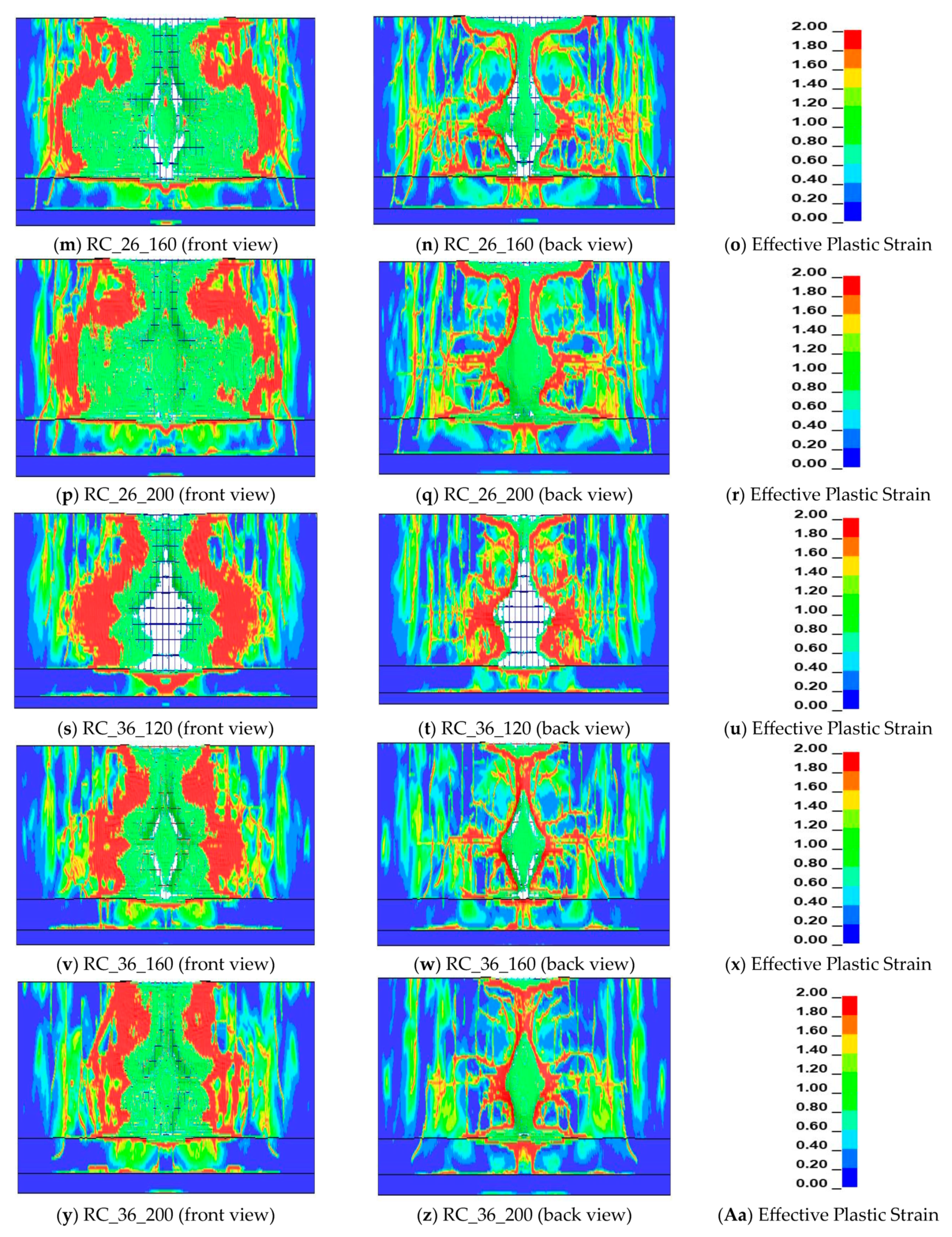
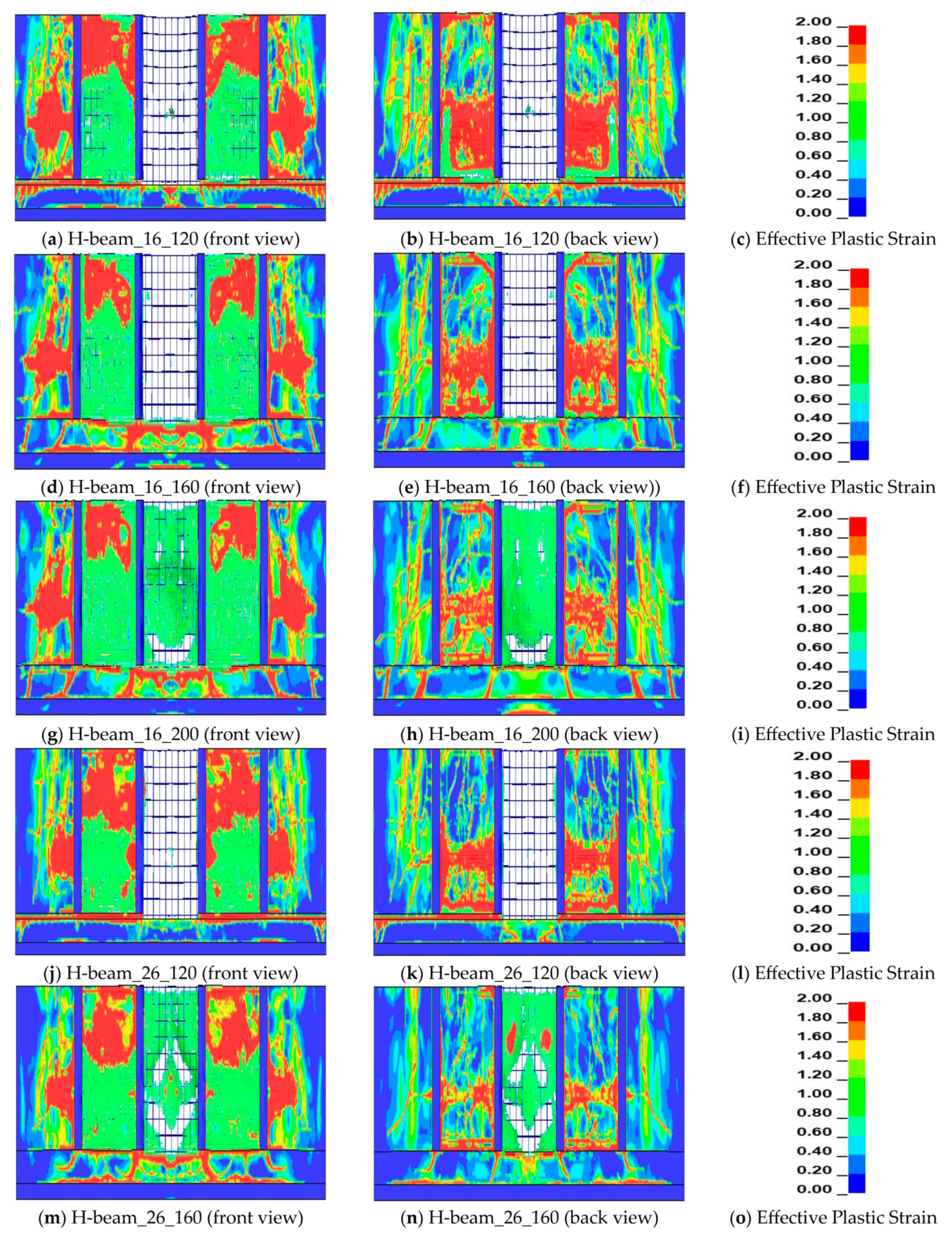
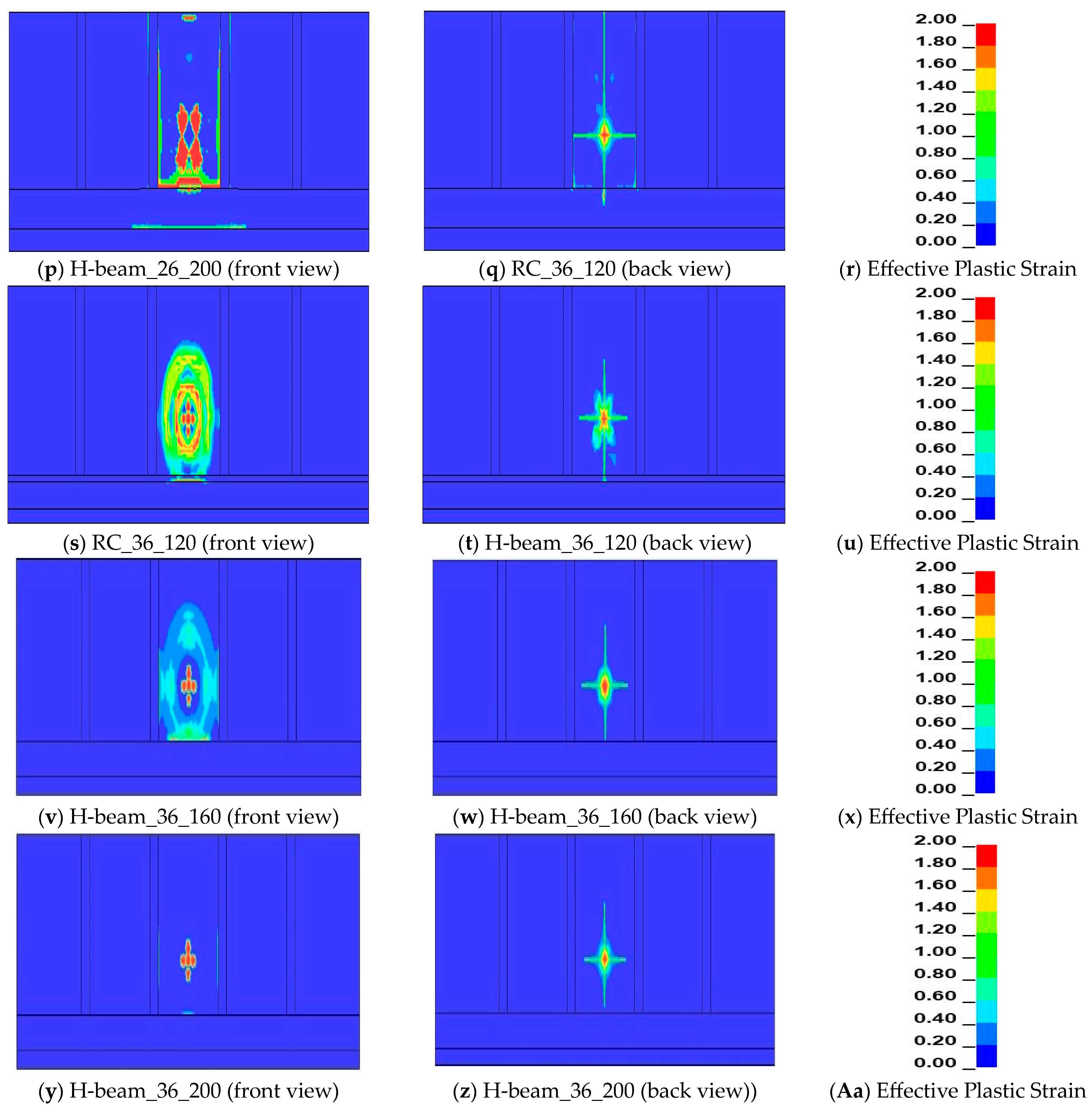
An explosion is a sudden process with rapid release of energy. This process last only for few milliseconds and produce a very high pressure and temperature. In this simulation the position of the TNT is 0.55 m from the ground level but the denotation point is at the center of TNT. The total termination time for the simulation is 10 milliseconds. Figure 10 and Figure 11 shows the failure of reinforced concrete and composite protection wall during worse-case scenario of hydrogen gas explosion and an index of damage with strain softening. As the distance increase the damage area on the protection wall was reduced for wall thickness of 0.12 m. But the stand-off distance till 3.6 m for 0.12 wall thickness is not sufficient to resist blast wave. Fragmentation area of protection wall is also high and can cause secondary accident during worse-case scenario and erosion of concrete elements is high in Figure 10 the erode elements had no color. Increasing the stand-off distance and thickness of wall i.e., at 3.6 m and wall thickness of 0.2 m for reinforcement concrete protection wall the damage area is lower than 0.12 m and 1.6 m of stand-off distance. Using of H-beam as a composite structure the damage area on the protection was area was comparatively lower than the reinforced concrete.

4.4. Failure on Reinforced Concrete and Composite Protection Wall during 30 kg of Hydrogen Gas Explosion

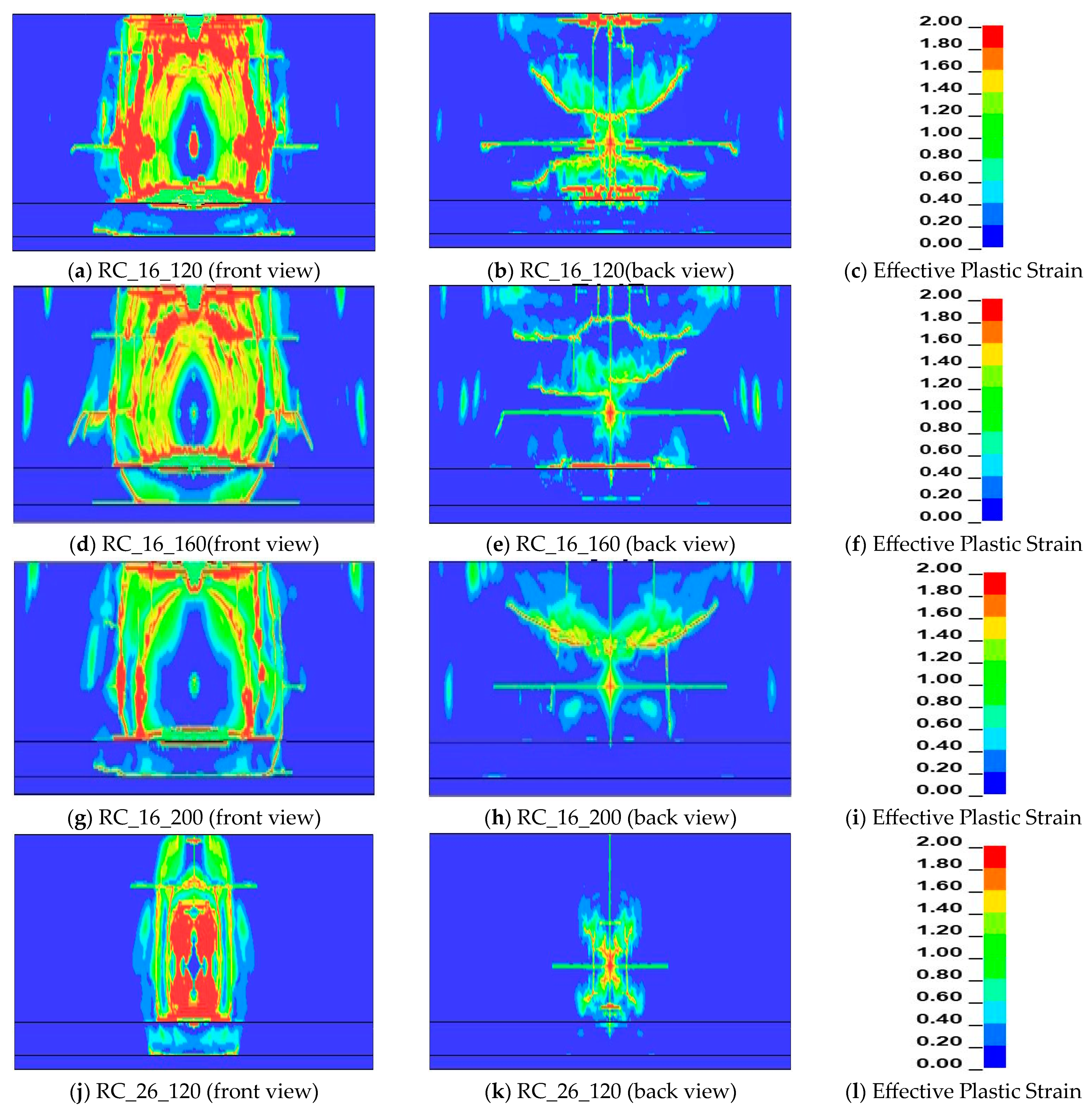
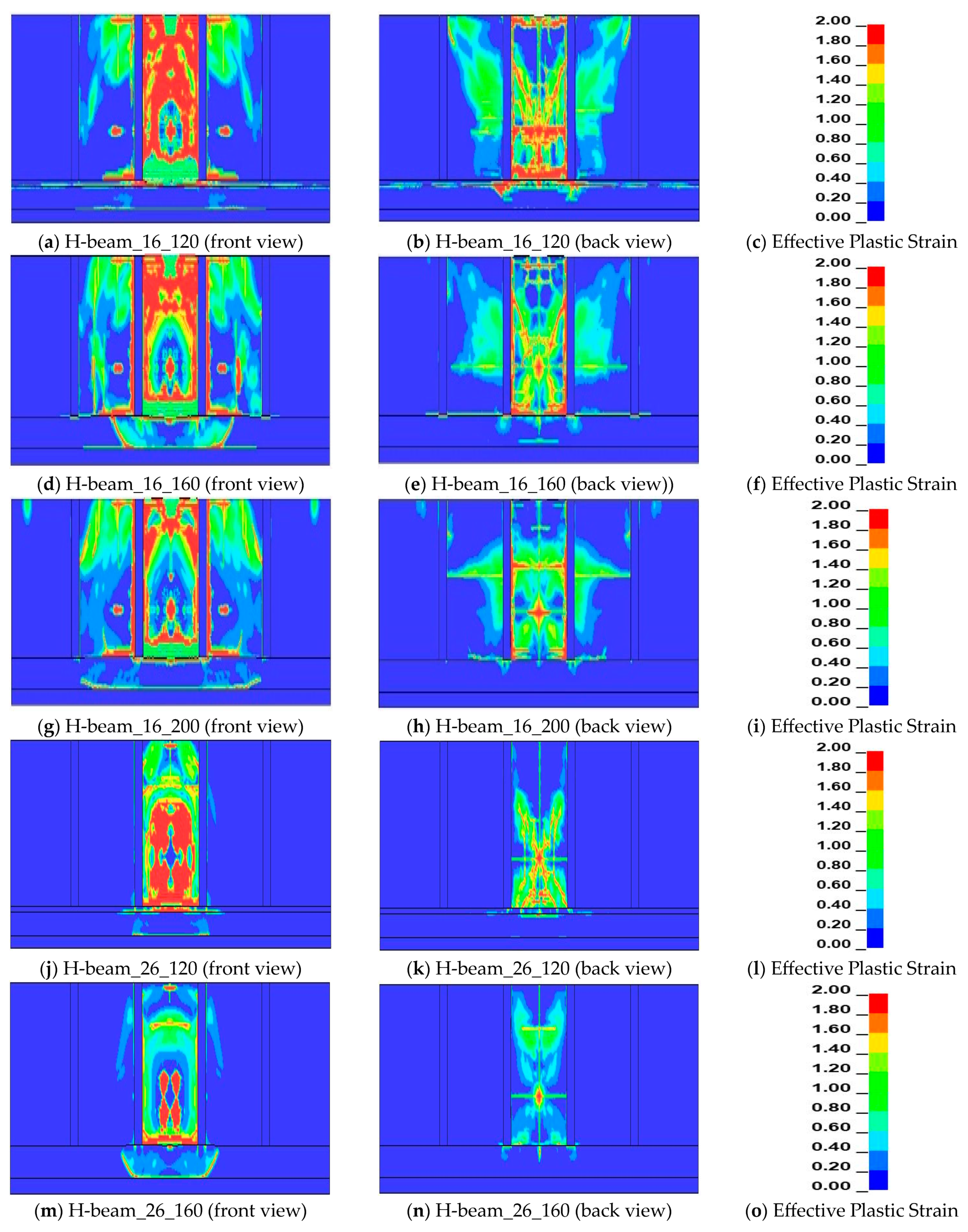
From equation 1 the TNT equivalent of 30 kg of hydrogen gas cylinder was 6.93 kg. In this simulation the position of the TNT is 0.55 m from the ground level but the denotation point is at the height of 0.75 m from the ground level. The total termination time for the simulation is 10 milliseconds. Figure 12 and Figure 13 shows the failure of reinforced concrete and composite protection wall during 30 kg of hydrogen gas explosion. As the distance increase the damage area on the protection wall was reduced for wall thickness of 0.12 m. But the stand-off distance till 3.6 m for 0.12 wall thickness is not sufficient to resist blast wave. But the fragmentation of protection wall reduced compare with worse-case scenario explosion. Increasing the stand-off distance and thickness of wall i.e., at 3.6 m and wall thickness of 0.2 m for reinforcement concrete protection wall the damage area is lower than 0.12 m and 1.6 m of stand-off distance. Using of H-beam as a composite structure the damage area on the protection was area was comparatively lower than the reinforced concrete. For 30 kg hydrogen gas explosion under this scenario using of H-beam can reduce the damage on protection wall at the wall thickness of 0.2 m.

5. Conclusions

This study evaluates the finite element analysis of the reinforced concrete protection wall model from the KGS FP217, and composite structures were performed to investigate the behavior of the protection wall under a hydrogen gas tank explosion in a worst-case scenario through the TNT equivalent method. In addition, this study also compares the spherical free air blast between ConWep and ALE simulation with different distances between TNT and the protection wall. Following are the conclusion from this study.
1. To decrease the displacement and cracks on the structure after an explosion, the placement of an H-beam and reinforcement technique should be used. The use of an H-beam in reinforced concrete improves blast performance by increasing the blast capacity and better controlling displacement. In comparison with the distance between reinforced concrete protective structure at 1.6 m and 3.6 m the displacement reduce from 250 mm to 109 mm at wall thickness of 0.12 m, whereas for the composite structure the displacement reduce from 245 mm to 68 mm.
2. Blast scenario could be infinite, and with increasing the standoff distance, pressure values, damage, and displacement values decrease. When the standoff distance between the protection wall and the explosion is the same for reinforced concrete and composite structure protection wall, the deflection at the center is nearly the same, but with increasing the distance between the explosive and protection wall, the displacement and damage on the structure reduce. At a standoff distance of 1.6 m the structure collapsed, and at a distance of 3.6 m the structure had moderate damage after an explosion for worse-case scenario. When the thickness of the protection wall increased to 200 mm the structure gets low damage for both reinforced and composite structure. At the distance of 3.6 m the displacement decreases from 109 mm to 53 mm for reinforced concrete protection wall with the thickness of 0.12 m and 0.2 m, respectively.
3. According to simulation results for the worst-case scenario, the minimum requirement of the barrier wall, as in KGS FP217, is not safe at a distance of 1.6 m after the hydrogen gas tank explosion. During the site visit to hydrogen gas storage, it was found that the distance between the protection wall and storage was 1.53 m. Moreover, the minimum distance between the protection wall and the hydrogen gas tank is not mentioned in the code book. Incident pressure obtained from the ALE simulation and ConWep during the worst-case scenario explosion of different variables may be taken as a guideline for the selection of protection structure and standoff distance between the protection wall and hydrogen gas tank storage.
4. Use of H-beam as a composite structure during 30 kg of hydrogen gas explosion had minimum damage at a stand-off distance of 3.6 m compare with worse -case scenario.
5. Good agreement between ConWep and ALE simulation for incident pressure at spherical free-air burst. This incident pressure can be taken as a reference to predict the blast pressure.

Author Contributions

Conceptualization, S.K., T.O. and C.P.; methodology, S.K., T.O. and C.P.; software, S.K., T.O. and C.P.; formal analysis, S.K., T.O. and C.P.; writing—original draft preparation, S.K., T.O., T.J. and C.P.; writing—review and editing, S.K., T.O., T.J. and C.P. All authors have read and agreed to the published version of the manuscript.

Funding

This research was supported by “Regional Innovation Strategy (RIS)” through the National Research Foundation of Korea (NRF) funded by the Ministry of Education (MOE) (2022RIS-005) and by the Korea Institute of Energy Technology Evaluation and Planning (KETEP) and the Ministry of Trade, Industry and Energy (MOTIE) of the Republic of Korea (No. 20215810100020).

Institutional Review Board Statement

Not applicable.

Informed Consent Statement

Not applicable.

Data Availability Statement

Not applicable.

Conflicts of Interest

The authors declare no conflict of interest.

References

  1. Balat, M. Potential Importance of Hydrogen as a Future Solution to Environmental and Transportation Problems. Int. J. Hydrogen Energy 2008, 33, 4013–4029. [Google Scholar] [CrossRef]
  2. South Korea’s Hydrogen Industrial Strategy. Available online: https://www.csis.org/analysis/south-koreas-hydrogen-industrial-strategy (accessed on 2 February 2023).
  3. Eckhoff, R.K. Explosion Hazards in the Process Industries; Elsevier: Amsterdam, The Netherlands, 2016; ISBN 9780128032732. [Google Scholar]
  4. Hydrogen Safety—Wikipedia. Available online: https://en.wikipedia.org/wiki/Hydrogen_safety (accessed on 2 February 2023).
  5. Pasman, H.J.; Rogers, W.J. Safety Challenges in View of the Upcoming Hydrogen Economy: An Overview. J. Loss Prev. Process Ind. 2010, 23, 697–704. [Google Scholar] [CrossRef]
  6. Khan, R.; Farooq, S.H.; Usman, M. Blast Loading Response of Reinforced Concrete Panels Externally Reinforced with Steel Strips. Infrastructures 2019, 4, 54. [Google Scholar] [CrossRef] [Green Version]
  7. Yao, S.; Zhang, D.; Chen, X.; Lu, F.; Wang, W. Experimental and Numerical Study on the Dynamic Response of RC Slabs under Blast Loading. Eng. Fail. Anal. 2016, 66, 120–129. [Google Scholar] [CrossRef]
  8. Nozu, T.; Tanaka, R.; Ogawa, T.; Hibi, K.; Sakai, Y. Numerical Simulation of Hydrogen Explosion Tests with a Barrier Wall for Blast Mitigation. In Proceedings of the 1st International Conference on Hydrogen Safety, Pisa, Italy, 8–10 September 2005. [Google Scholar]
  9. Liu, Y.; Yan, J.B.; Huang, F.L. Behavior of Reinforced Concrete Beams and Columns Subjected to Blast Loading. Def. Technol. 2018, 14, 550–559. [Google Scholar] [CrossRef]
  10. Nassr, A.A.; Razaqpur, A.G.; Tait, M.J.; Campidelli, M.; Foo, S. Experimental Performance of Steel Beams under Blast Loading. J. Perform. Constr. Facil. 2012, 26, 600–619. [Google Scholar] [CrossRef]
  11. Anandavalli, N.; Lakshmanan, N.; Iyer, N.R.; Samuel Knight, G.M.; Rajasankar, J. A Novel Modelling Technique for Blast Analysis of Steel-Concrete Composite Panels. Procedia Eng. 2011, 14, 2429–2437. [Google Scholar] [CrossRef] [Green Version]
  12. Bruhl, J.C.; Varma, A.H.; Kim, J.M. Static Resistance Function for Steel-Plate Composite (SC) Walls Subject to Impactive Loading. Nucl. Eng. Des. 2015, 295, 843–859. [Google Scholar] [CrossRef] [Green Version]
  13. Lan, S.; Lok, T.S.; Heng, L. Composite Structural Panels Subjected to Explosive Loading. Constr. Build. Mater. 2005, 19, 387–395. [Google Scholar] [CrossRef]
  14. Richard Liew, J.Y.; Wang, T.Y. Novel Steel-Concrete-Steel Sandwich Composite Plates Subject to Impact and Blast Load. Adv. Struct. Eng. 2011, 14, 673–688. [Google Scholar] [CrossRef]
  15. Zheng, Z.; Yu, J.; Wei, F.; Wu, J. Numerical Study of Blast Performance of Concrete Filled Double-Steel-Plate Composite Walls. Int. J. Prot. Struct. 2020, 11, 23–40. [Google Scholar] [CrossRef]
  16. KGS Code Gas Technical Standard Information System. Available online: https://cyber.kgs.or.kr/kgscode.Index.do (accessed on 2 March 2021).
  17. Center for Hydrogen Safety (CHS). Review: Hydrogen Tank Explosion in Gangneung, South Korea. Available online: https://www.aiche.org/chs/conferences/international-center-hydrogen-safety-conference/2019/proceeding/paper/review-hydrogen-tank-explosion-gangneung-south-korea (accessed on 5 January 2023).
  18. International Fire Code (IFC). Available online: https://codes.iccsafe.org/content/IFC2018 (accessed on 2 January 2023).
  19. Air, K. Comparison of Regulations Codes and Standards for Hydrogen Refueling Stations in Japan and France. In Proceedings of the International Conference on Hydrogen Safety, Adelaide, Australia, 25 September 2019. [Google Scholar]
  20. Center for Strategic and International Studies. China Unveils Its First Long-Term Hydrogen Plan. Available online: https://www.csis.org/analysis/china-unveils-its-first-long-term-hydrogen-plan (accessed on 5 January 2023).
  21. Focus on Hydrogen: Japan’s Energy Strategy for Hydrogen and Ammonia. Available online: https://www.cliffordchance.com/content/dam/cliffordchance/briefings/2022/08/focus-on-hydrogen-in-japan.pdf (accessed on 2 January 2023).
  22. Statista. Number of Hydrogen Fuel Stations by Country. 2022. Available online: https://www.statista.com/statistics/1026719/number-of-hydrogen-fuel-stations-by-country/?fbclid=IwAR3eFnTx9d8wkLUCIr3aVHsbm4Tmb8xBaPshE1nBmSt74jz-0QH9pa6OGaQ (accessed on 5 January 2023).
  23. Statista. South Korea: Hydrogen Fueling Stations Cumulative Number 2018–2030. Available online: https://www.statista.com/statistics/957810/south-korea-hydrogen-fueling-stations-cumulative-number/ (accessed on 5 January 2023).
  24. Statista. Hydrogen Demand Worldwide. Available online: https://www.statista.com/statistics/1121206/global-hydrogen-demand/ (accessed on 5 January 2023).
  25. Casal, J. Evaluation of the Effects and Consequences of Major Accidents in Industrial Plants, 2nd ed.; Fedor, J., Ed.; Elsevier: Amsterdam, The Netherlands, 2018; ISBN 9780128127667. [Google Scholar]
  26. Kwon, S.; Park, J. A Review of TNT Equivalent Method for Evaluating Explosion Energy Due to Gas Explosion. Korean Soc. Explos. Blasting Eng. 2015, 33, 1–13. [Google Scholar]
  27. Training Program Analysis for Hydrogen Releted Emergencies. Available online: https://academic.naver.com/article.naver?doc_id=939895533 (accessed on 20 December 2022).
  28. López, E.; Rengel, R.; Mair, G.W.; Isorna, F. Analysis of High-Pressure Hydrogen and Natural Gas Cylinders Explosions through TNT Equivalent Method. In Proceedings of the 5th Iberian Symposium on Hydrogen, Fuel Cells and Advanced Batteries, Tenerife, Spain, 5–8 July 2015. [Google Scholar] [CrossRef]
  29. Lopes, K.B.; Melo, P.F.F.F. Analysis of the Effects of Explosion of a Hydrogen Cylinder on the Transfer of Radioactive Liquid Wastes at Nuclear Power Stations. In Proceedings of the 2011 International Nuclear Atlantic Conference, Belo Horizonte, Brazil, 24–18 October 2011. [Google Scholar]
  30. Malvar, L.J.; Crawford, J.E.; Wesevich, J.W.; Simons, D. A Plasticity Concrete Material Model for DYNA3D. Int. J. Impact Eng. 1997, 19, 847–873. [Google Scholar] [CrossRef]
  31. Yin, X.; Li, Q.; Chen, B.; Xu, S. An Improved Calibration of Karagozian & Case Concrete/Cementitious Model for Strain-Hardening Fibre-Reinforced Cementitious Composites under Explosion and Penetration Loadings. Cem. Concr. Compos. 2023, 137, 104911. [Google Scholar] [CrossRef]
  32. Wu, Y.; Crawford, J.E. Numerical Modeling of Concrete Using a Partially Associative Plasticity Model. J. Eng. Mech. 2015, 141, 04015051. [Google Scholar] [CrossRef]
  33. Murray, Y. Users Manual for LS-DYNA Concrete Material Model 159; Federal Highway Administration: Washington, DC, USA, 2007; Volume 77. [Google Scholar]
  34. Yin, X.; Li, Q.; Xu, X.; Chen, B.; Guo, K.; Xu, S. Investigation of Continuous Surface Cap Model (CSCM) for Numerical Simulation of Strain-Hardening Fibre-Reinforced Cementitious Composites against Low-Velocity Impacts. Compos. Struct. 2023, 304, 116424. [Google Scholar] [CrossRef]
  35. Manual, K.U.S.; Ii, V. Ls-Dyna Manual Volume Ii R6.10; LSTC: Driffield, UK, 2012; Volume 2. [Google Scholar]
  36. Rashed, A.; Yazdani, M.; Babaluo, A.A.; Hajizadeh Parvin, P. Investigation on High-Velocity Impact Performance of Multi-Layered Alumina Ceramic Armors with Polymeric Interlayers. J. Compos. Mater. 2016, 50, 3561–3576. [Google Scholar] [CrossRef]
  37. Gomah, M.; Demiral, M. An Experimental and Numerical Investigation of an Improved Shearing Process with Different Punch Characteristics. Stroj. Vestn. J. Mech. Eng. 2020, 66, 375–384. [Google Scholar] [CrossRef]
  38. Wang, I.T. 1440. Simulation and Experimental Validation of the Dynamic Pressure of Shock Wave under Free-Field Blast Loading. J. Vibroeng. 2014, 16, 3547–3556. [Google Scholar]
  39. Wang, W.; Zhang, D.; Lu, F.; Wang, S.C.; Tang, F. Experimental Study and Numerical Simulation of the Damage Mode of a Square Reinforced Concrete Slab under Close-in Explosion. Eng. Fail. Anal. 2013, 27, 41–51. [Google Scholar] [CrossRef]
  40. Zhao, C.F.; Chen, J.Y. Damage Mechanism and Mode of Square Reinforced Concrete Slab Subjected to Blast Loading. Theor. Appl. Fract. Mech. 2013, 63–64, 54–62. [Google Scholar] [CrossRef]
  41. Sadique, M.R.; Zaid, M.; Alam, M.M. Rock Tunnel Performance Under Blast Loading Through Finite Element Analysis. Geotech. Geol. Eng. 2022, 40, 35–56. [Google Scholar] [CrossRef]
  42. Protective, F.O.F.; Weapons, F.O.R.C. {TM} 5-855-1: Fundamentals of Protective Design for Conventional Weapons; US Department of the Army: Washington, DC, USA, 1986. [Google Scholar]
Figure 1. (a) Hydrogen tank explosion occurred in Gangneung, South Korea on May 2019; (b) Hydrogen gas station site visit at Samcheok, South Korea.
Applsci 13 03744 g001
Figure 2. (a) Cumulative number of hydrogen fueling stations from 2018 to 2030; (b) Hydrogen demand worldwide from 2019 to 2021 with forecast for 2030.
Applsci 13 03744 g002
Figure 3. Pressure and time relation at the free air blast wave.
Applsci 13 03744 g003
Figure 4. (a) KGS FP127 model dimension with 120 mm protection wall thickness; (b) Model dimension with 160 mm protection wall thickness; (c) Model dimension with 200 mm protection wall thickness.
Applsci 13 03744 g004
Figure 5. (a) LS-DYNA model for simulation; (b) LS-DYNA model with composite structure.
Applsci 13 03744 g005
Figure 6. Detail reinforcement of protection wall (not in scale).
Applsci 13 03744 g006
Figure 7. Displacement vs time graph from simulation results.
Applsci 13 03744 g007
Figure 8. Incident pressure vs time curve from Conwep and LS-DYNA.
Applsci 13 03744 g008
Figure 9. (a) Position of displacement probe; (b) Reinforced and composite protection structure displacement at a distance of 1.6 m from different elements; (c) Reinforced and composite protection structure displacement at a distance of 2.6 m from different elements; (d) Reinforced and composite protection structure displacement at a distance of 1.6 m from different elements; (e) Reinforced and composite protection structure displacement at a distance of 2.6 m from different elements; (f) Reinforced and composite protection structure displacement at a distance of 1.6 m from different elements; (g) Reinforced and composite protection structure displacement at a distance of 2.6 m from different elements; (h) Reinforced and composite protection structure displacement at a distance of 3.6 m from different elements.
Applsci 13 03744 g009aApplsci 13 03744 g009bApplsci 13 03744 g009c
Figure 10. Effective plastic strain on reinforced concrete with different thickness and stand-off distance during Worse Case Scenario.
Applsci 13 03744 g010aApplsci 13 03744 g010b
Figure 11. Effective plastic strain on composite structure protection wall with different thickness and stand-off distance during Worse Case Scenario.
Applsci 13 03744 g011aApplsci 13 03744 g011b
Figure 12. Effective plastic strain on reinforced concrete with different thickness and stand-off distance during 30 kg of Hydrogen Gas Explosion.
Applsci 13 03744 g012aApplsci 13 03744 g012b
Figure 13. Effective plastic strain on composite structure protection wall with different thickness and stand-off distance during 30 kg of Hydrogen Gas Explosion.
Applsci 13 03744 g013aApplsci 13 03744 g013b
Table 1. Minimum requirement of barriers wall thickness in different countries [16,19].
CountryMinimum Requirement of Barrier Wall
South Korea120 mm
Japan120 mm
FranceSimple wall satisfying REI120 of European fire resistance class
Table 2. Number of hydrogen fueling stations in different countries (2022).
CountryNumber of Hydrogen Fueling Stations (2022)
China250
Japan161
South Korea141
Germany93
France21
Netherlands11
Canada9
Table 3. Concrete materials properties (K&C model).
ParameterValue
Density2.4 × 10−6 kg/mm3
Compressive Strength0.035 GPa
Table 4. Properties of rebar and H-beam.
ParametersMAT_JHONSON_COOK (H-Beam)MAT_PLASTIC_KINEMATIC (Steel Rebar)
Density7.85 × 10−6 kg/mm37.85 × 10−6 kg/mm3
Young’s modulus200 GPa205 GPa
Poison ratio0.260.3
Shear Modulus88 GPa
Yield stress 0.42 GPa
Strain rate parameter (SRC) 40.4
Strain rate parameter (SRP) 5
Failure strain (FS) 0.25
A0.28 GPa
B0.5 GPa
N0.26
C0.22
M0.91
Damage (D1)0.40
Damage (D2)1.10
Damage (D3)0.1
Damage (D4)0.009
Damage (D5)0
Table 5. Materials properties of air, TNT and soil [38].
ComponentUnit (Kg, mm, ms)
AirMAT_NULL
ROPCMUTERODCERODTMPR
1.293 × 10−9000000
*EOS_LINEAR_POLYNOMIAL
C0C1C2C3C4C5C6
00000.40.40
E0Vo
2.50E−041
TNT*MAT_HIGH_EPLOSIVE_BURN
RODPCJBETAKGSIGY
1.630 × 10−68193280000
*EOS_JWL
ABR1R2OMEGE0Vo
609.77212.954.51.40.2591
Soil
RONPLOTSPGRAVRHOWATVNGAMMARITERMAX
2.35E−0632.791.0 × 10−61.1010
KGPHIMAXAHYPCOHECCENAN
0.003250.00131.11.0 × 10−76.2 × 10−60.70.0
Table 6. Compare present study with previous study.
VariableTNT Weight (kg)Central Displacement form Experiment [39] (mm)Central Displacement from Simulation [39] (mm)Central Displacement from Simulation [40] (mm)Central Displacement from Simulation
[41] (mm)
Central Displacement from This Study (mm)Error (%)
10.21088.88.159.258.1
20.31151312.712.2514.394.23
Table 7. Compare peak pressure between ConWep and LS-DYNA.
Distance (mm)Peak Pressure (kPa)Error (%)
ConWepLS-DYNA
160034333234.835.77
260015641588.021.54
3600857872.741.84
Disclaimer/Publisher’s Note: The statements, opinions and data contained in all publications are solely those of the individual author(s) and contributor(s) and not of MDPI and/or the editor(s). MDPI and/or the editor(s) disclaim responsibility for any injury to people or property resulting from any ideas, methods, instructions or products referred to in the content.