
Design and Test of a Levelling System for a Mobile Safflower Picking Platform

Abstract
:1. Introduction
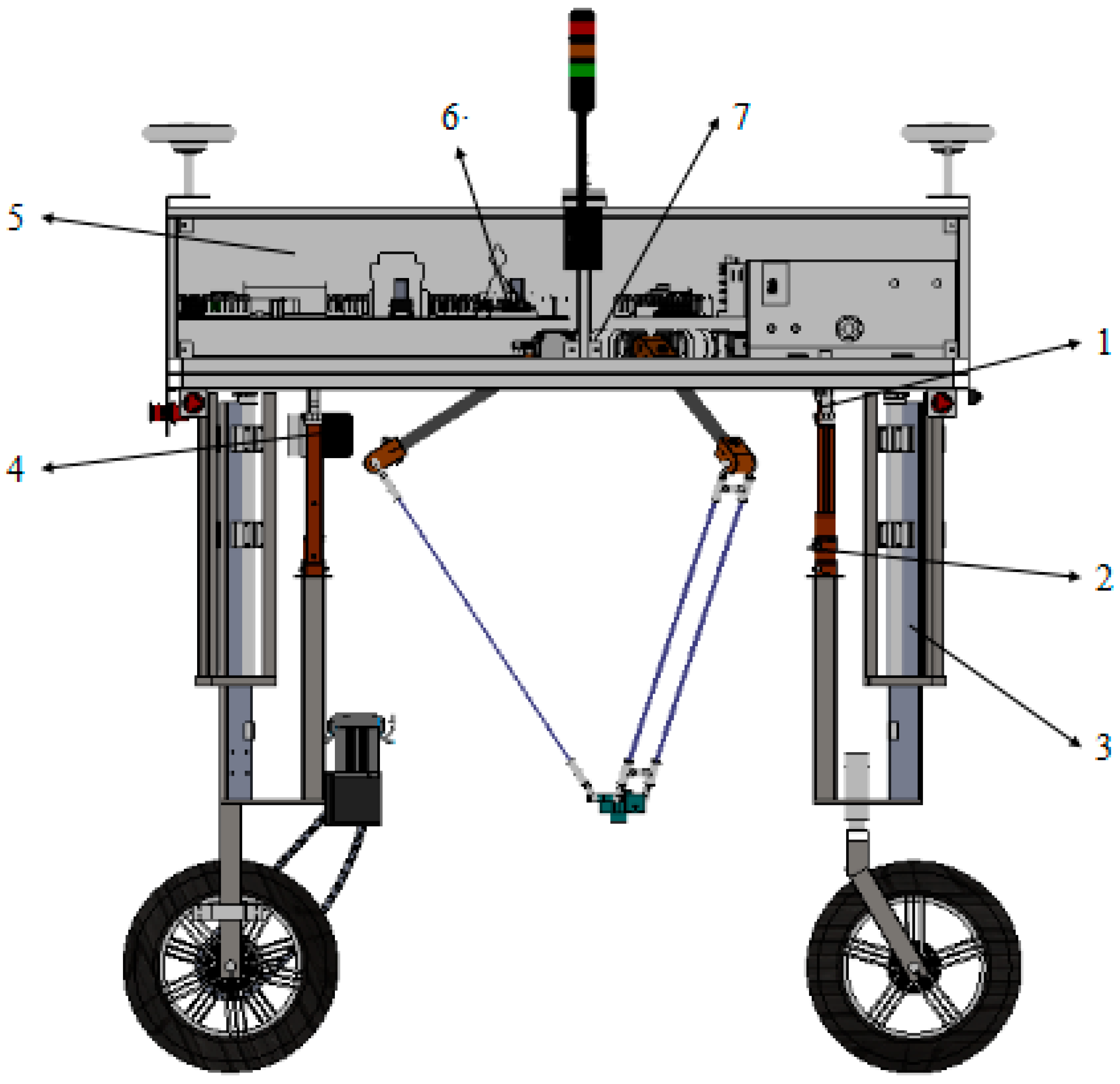
2. Overall Structure and Working Principle
2.1. Overall Design
2.2. Operational Principle
3. Levelling Strategy and Analysis
3.1. Mathematical Modelling of the Mobile Platform
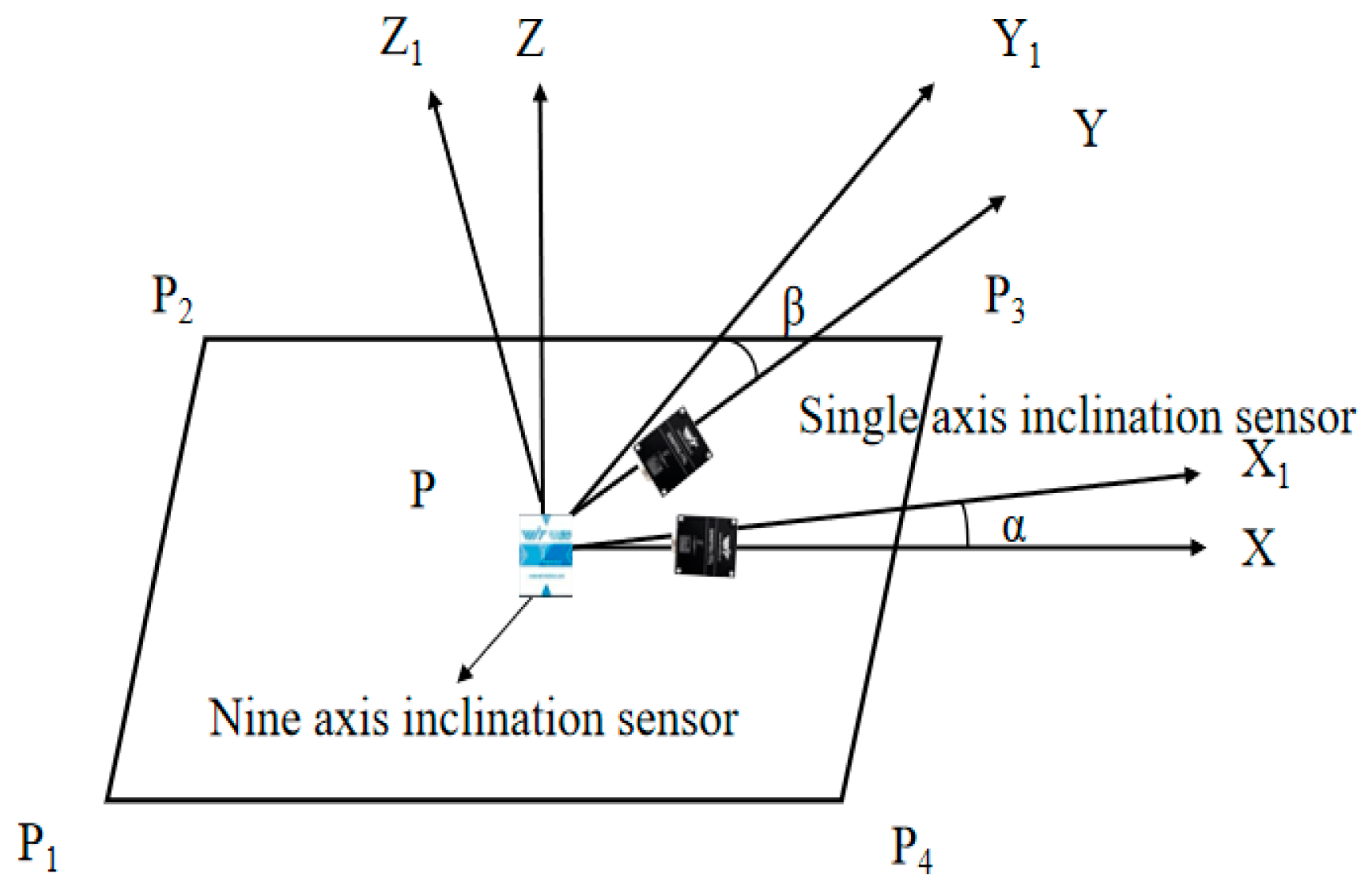
3.2. Levelling Accuracy Analysis
3.3. Levelling Limit Range
- a
- When the X-axis is inclined, P1 and P2 outriggers rise to the highest point. At this time, Lmax = 0.2 m, and dX = 1 m. According to the trigonometric function, the maximum allowable inclination angle at this time is:
- b
- When the Y-axis is inclined, the P2 and P3 outriggers rise to the highest point. At this time, Lmax = 0.2 m and dX = 1 m. According to the trigonometric function, the maximum allowable inclination angle at this time is:
- c
- When inclination occurs on the diagonal, the P3 outrigger rises to the highest point, and the P1 outrigger height remains unchanged. At this time, Lmax = 0.2 m, and dX-Y = 21/2 m. According to the trigonometric function relationship, the maximum allowable inclination angle at this time is:
4. Control System Design
4.1. Hardware Design
4.2. Software Design
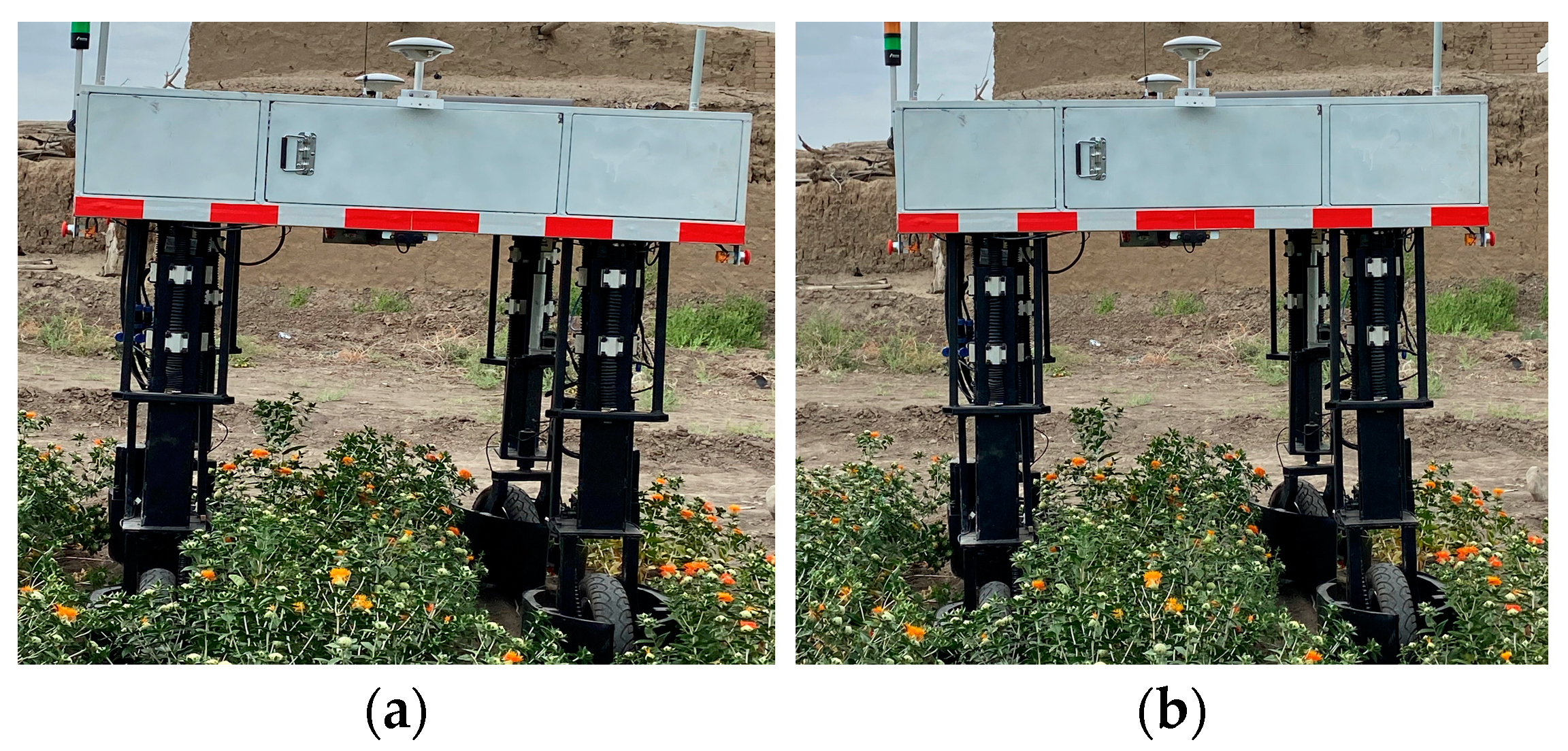
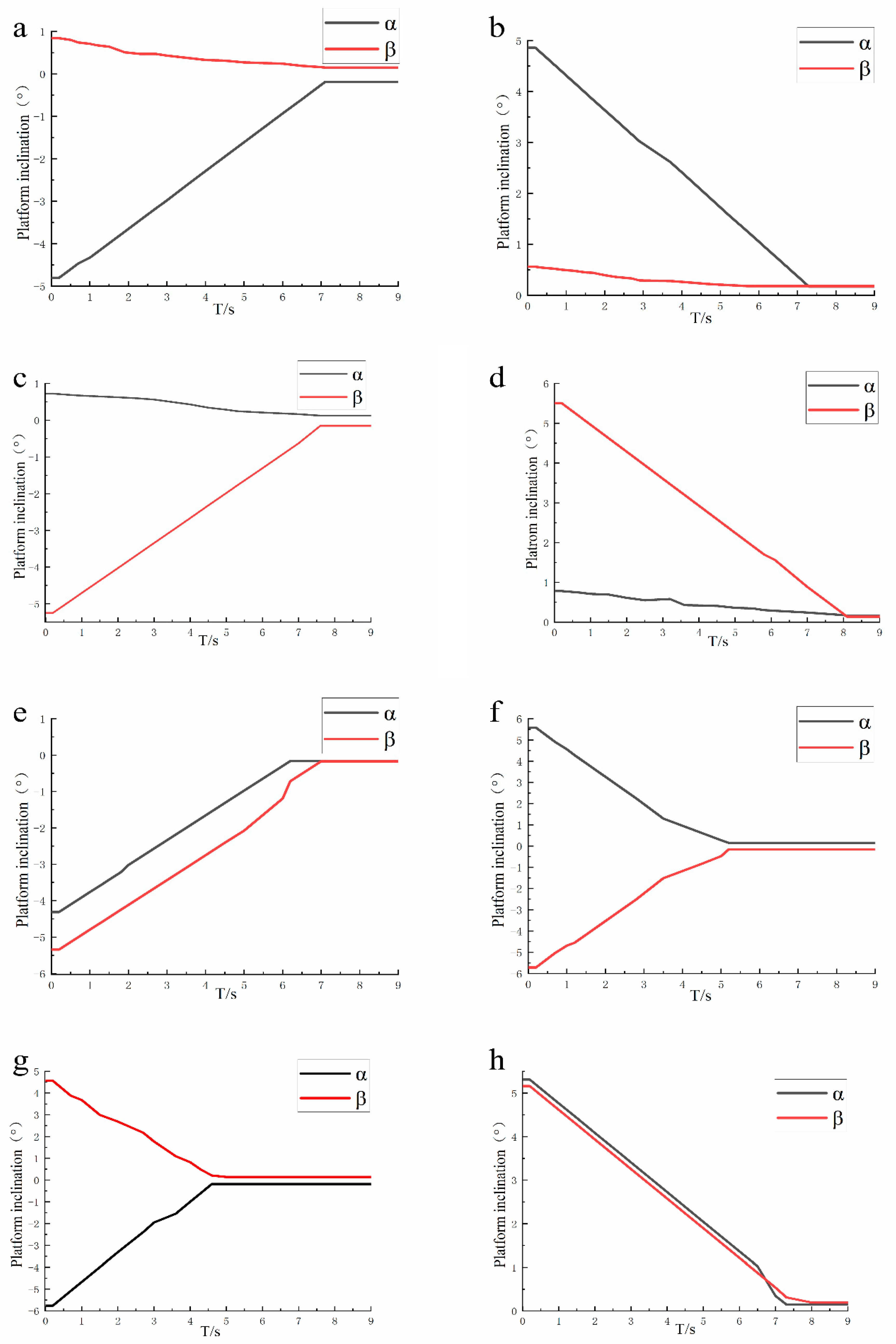
5. Test and Result Analysis
6. Conclusions
Author Contributions
Funding
Institutional Review Board Statement
Informed Consent Statement
Data Availability Statement
Conflicts of Interest
References
- Bijanzadeh, E.; Moosavi, S.; Bahadori, F. Quantifying water stress of safflower (Carthamus tinctorius L.) cultivars by crop water stress index underdifferentirrigationregimes. Heliyon 2022, 8, e09010. [Google Scholar] [CrossRef] [PubMed]
- De Oliveira Neto, S.S.; Zeffa, D.M.; Freiria, G.H.; Zoz, T.; da Silva, C.J.; Zanotto, M.D.; Sobrinho, R.L.; Alamri, S.A.; Okla, M.K.; AbdElgawad, H. Adaptability and Stability of Safflower Genotypes for Oil Production. Plants 2022, 11, 708. [Google Scholar] [CrossRef] [PubMed]
- Gongora, B.; de Souza SN, M.; Bassegio, D.; Santos, R.F.; Siqueira JA, C.; Bariccatti, R.A.; Gurgacz, F.; Secco, D.; Tokura, L.K.; Sequinel, R. Comparison of emissions and engine performance of safflower and commercial biodiesels. Ind. Crops Prod. 2022, 179, 114680. [Google Scholar] [CrossRef]
- Xu, X.; Cheng, L.; Guo, Y.; Li, J.; Ke, Y. A modeling and calibration method of heavy-duty automated fiber placement robot considering compliance and joint-dependent errors. J. Mech. Robot. 2023, 15, 061011. [Google Scholar] [CrossRef]
- Yu, Z.; Wang, X. Design and Research on automatic levelling device of paddy field compound land leveler. Res. Agric. Mech. 2017, 39, 175–179, (In Chinese with English abstract). [Google Scholar]
- Liu, P.; Wang, C.; Li, H.; Zhang, M.; Wei, W.; Zhang, H. Design and test of dynamic levelling chassis for agricultural profiling walking in Hilly and mountainous areas. J. Agric. Mach. 2018, 49, 74–81, (In Chinese with English abstract). [Google Scholar]
- Zhou, H.; Hu, L.; Luo, X.; Zhao, R.; Xu, Y.; Yang, W. Design and test of automatic levelling system for rotary cultivator. J. Agric. Mach. 2016, 47, 117–123, (In Chinese with English abstract). [Google Scholar]
- Tang, J.; Liu, X. The Design of Electrical Putter Car Moving Robots Based on Microcontroller Control. DEStech Trans. Eng. Technol. Res. 2017. [Google Scholar] [CrossRef] [PubMed]
- Jiao, R.; Chen, C.; Wang, F. The Study of Virtual Leg Problems on Electromechanical Vehicle Platform with Four-Point Support. In Applied Mechanics and Materials; Trans Tech Publications Ltd.: Stafa-Zurich, Switzerland, 2014; Volume 540, pp. 399–402. [Google Scholar] [CrossRef]
- Zhu, D. Research on Automatic Levelling System of Vehicle Mounted Radar Antenna Based on Parallel Support Mechanism; Beijing Jiaotong University: Beijing, China, 2008; (In Chinese with English abstract). [Google Scholar]
- Liu, K.; Kang, S.; Cao, Z.; Liu, R.; Ding, Z. Angle and Force Hybrid Control Method for Electrohydraulic Leveling System with Independent Metering. Math. Probl. Eng. 2021, 2021, 6642597. [Google Scholar] [CrossRef]
- Zhang, L.; Shao, J.P.; Sun, G.T.; Gao, B.W.; Jin, Z.H.; Zhu, J.; Mu, X.N. Research on Automatic Leveling System of Railway Rescue Cran. Adv. Mater. Res. 2014, 909, 241–246. [Google Scholar] [CrossRef]
- Wos, P.; Dindorf, R.; Takosoglu, J. Bricklaying Robot Lifting and Levelling System. Commun. Sci. Lett. Univ. Zilina 2021, 23, B257–B264. [Google Scholar] [CrossRef]
- Meng, B. Control of Robot Arm Motion Using Trapezoid Fuzzy Two-Degree of Freedom PID algorithm. Symmetry 2020, 12, 665. [Google Scholar] [CrossRef] [Green Version]
- Han, J.; Xu, W. Virtual 3D model angle control of six axis gyroscope mpu6050. SCM Embed. Syst. Appl. 2017, 17, 43–44, (In Chinese with English abstract). [Google Scholar]
- Zhang, K.; Li, C.; Zhang, W. Wireless Sensor Data Fusion Algorithm Based on the Sensor Scheduling and Batch Estimate. Int. J. Future Comput. Commun. 2013, 2, 333. [Google Scholar] [CrossRef] [Green Version]


| Manual Levelling Button Label | Movement Trend | From |
|---|---|---|
| 0 | Manual/Automatic | Controller |
| 1 | 1 Up | Linear actuator1 |
| 2 | 2 Up | Linear actuator 2 |
| 3 | 3 Up | Linear actuator 3 |
| 4 | 4 Up | Linear actuator 4 |
| 11 | 1 Down | Linear actuator1 |
| 22 | 2 Down | Linear actuator 2 |
| 33 | 3 Down | Linear actuator 3 |
| 44 | 4 Down | Linear actuator 4 |
| 5 | All up | Linear actuators 1, 2, 3, 4 |
| 6 | All down | Linear actuators 1, 2, 3, 4 |
| 7 | Reset | Linear actuators 1, 2, 3, 4 |
| 8 | Cease | Linear actuators 1, 2, 3, 4 |
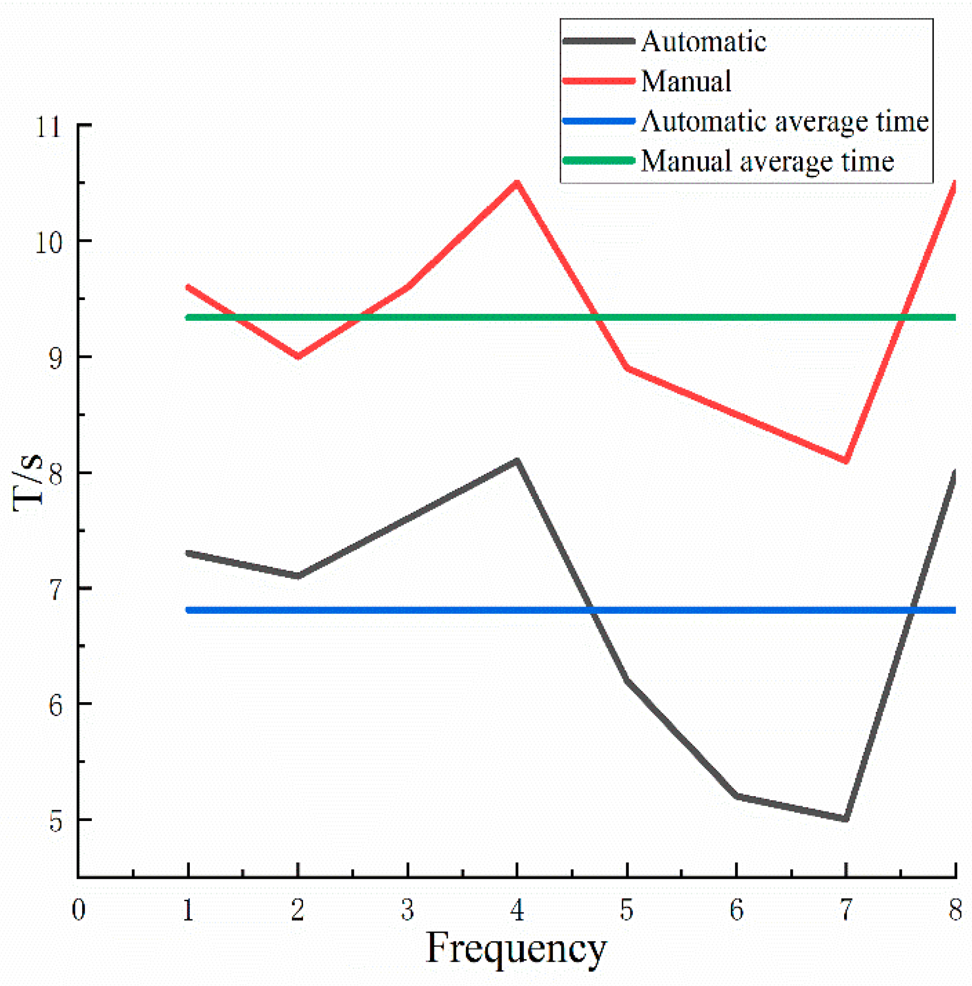
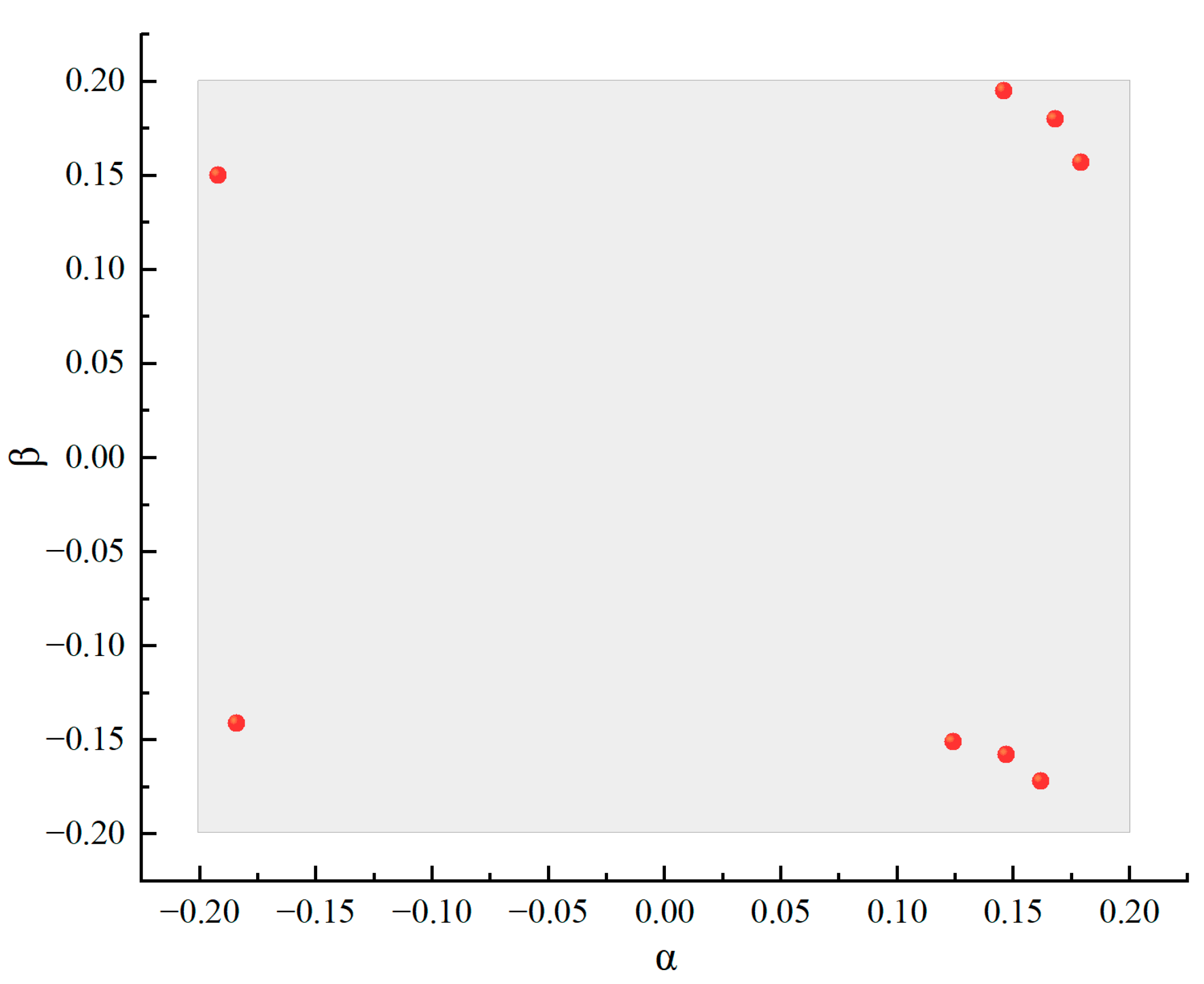
| Tilt State | before Levelling | after Levelling | Levelling Time(s) | ||
|---|---|---|---|---|---|
| α | β | α | β | ||
| Front lowest | −4.806° | 0.84 | −0.192° | 0.15° | 7.1 |
| Rear lowest | 4.86° | 0.56° | 0.168° | 0.18° | 7.3 |
| Left lowest | 0.724° | −5.25° | 0.124° | −0.151° | 7.6 |
| Right lowest | 0.783° | 5.51° | 0.179° | 0.157° | 8 |
| Left front lowest | −4.31° | −5.34° | 0.162° | −0.172° | 7 |
| Right front lowest | −5.76° | 4.56° | −0.184° | −0.141° | 5 |
| Left rear lowest | 5.58° | −5.71° | 0.147° | −0.158° | 5.2 |
| Right rear lowest | 5.31° | 5.16° | 0.146° | 0.195° | 7.3 |
Disclaimer/Publisher’s Note: The statements, opinions and data contained in all publications are solely those of the individual author(s) and contributor(s) and not of MDPI and/or the editor(s). MDPI and/or the editor(s) disclaim responsibility for any injury to people or property resulting from any ideas, methods, instructions or products referred to in the content. |
© 2023 by the authors. Licensee MDPI, Basel, Switzerland. This article is an open access article distributed under the terms and conditions of the Creative Commons Attribution (CC BY) license (https://creativecommons.org/licenses/by/4.0/).
Share and Cite
Guo, H.; Lu, H.; Gao, G.; Wu, T.; Chen, H.; Qiu, Z. Design and Test of a Levelling System for a Mobile Safflower Picking Platform. Appl. Sci. 2023, 13, 4465. https://doi.org/10.3390/app13074465
Guo H, Lu H, Gao G, Wu T, Chen H, Qiu Z. Design and Test of a Levelling System for a Mobile Safflower Picking Platform. Applied Sciences. 2023; 13(7):4465. https://doi.org/10.3390/app13074465
Chicago/Turabian StyleGuo, Hui, Hao Lu, Guomin Gao, Tianlun Wu, Haiyang Chen, and Zhaoxin Qiu. 2023. "Design and Test of a Levelling System for a Mobile Safflower Picking Platform" Applied Sciences 13, no. 7: 4465. https://doi.org/10.3390/app13074465