Abstract
This research paper numerically studies how hydrocarbon additives affect hydrogen combustion in the process of complex fuel burning on the example of the combustible foam representing the heptane-in-water emulsion foamed with a hydrogen–oxygen mixture. It is demonstrated that the two-phase hydrodynamic model with an account of foam structure and chemical kinetics reproduces quite accurately, at least at the qualitative level, the experimentally observed features of foamed emulsion combustion. Due to this, it is concluded that a proposed model can be fruitfully used for the interpretation of the combustion features observed in such a complex combined fuel. Based on the obtained numerical data, it is found that there are two main possibilities related to the hydrogen–hydrocarbon chemistry interactions. In the case of near-stoichiometric, hydrocarbons act mainly as an inhibitor of hydrogen combustion; however, for lean hydrogen–oxygen mixtures, flame propagation is determined by the joint hydrocarbon and hydrogen oxidation kinetics. Herewith, the hydrocarbon burns together with the hydrogen inside the flame front in the case of slow combustion, while in the case of high-speed combustion, hydrogen oxidation kinetics becomes predominant, and hydrocarbons evaporate and burn behind the flame front, causing a lesser effect on the flame dynamics.
1. Introduction
The design of novel technologies for efficient and clean energy is one of today’s topical challenges, so the development of promising complex fuels is in demand. Here, complexity means the combination of different fuels to optimize their features when applied to the energy industry [1]. Nowadays, there are numerous concepts under consideration, among which there are: emulsion fuels [2,3], including water-containing emulsions [4], coal-water slurries [5,6], and liquid and gaseous fuels blends with active additives such as hydrogen [7,8,9], which is also a promising renewable fuel by itself [10,11]. Some of the conceptual fuels listed above contain water as one of the components. Water added to the fuel acts as an inert heat carrier and allows reducing harmful emissions [12]. Thus, for example, water as a part of emulsified fuel [13] defines lower production of . That is one of the essential reasons for water use as a part of complex fuels especially in combination with hydrogen (since hydrogen combustion is known as a source of higher temperatures and therefore higher emission of ). It is known that water addition in the form of ultra-fine mist represents one of the most efficient ways for explosion suppression [14]. At the same time, when using relatively coarse water droplets with a diameter of ∼50–100 m, no suppression of the explosion takes place [15]. Moreover, the combustion process can even be intensified [16].
Recently in [17], the foamed emulsion as a brand new type of water-containing fuel system was proposed. While the energy efficiency of such a fuel is still questionable, it can be fruitfully used as a base for the technology of water-saturated hydrocarbon utilization [18]. The addition of hydrogen into the foamed emulsion [19] leads to the significant intensification of the burning process, and even modes with flame acceleration and transition to detonation can take place, such as in aqueous foams bubbled with hydrogen–oxygen mixtures [20]. Hydrogen by itself represents a promising addition to traditional fossil fuels and biofuels. Its presence in the fuel blend causes combustion intensification and stabilization [21], as well as the pollutant reduction [22], including soot [23]. In the particular case of foamed emulsions combustion, hydrogen addition leads to flame acceleration.
It is interesting to note that the inner structure of the combustible foam plays one of the most important roles in the non-steady flame development in the foam. This can be concluded from the very first experimental works on the combustion of dry foams [24,25,26]. At the same time, a recently proposed mathematical model [27] reproducing experimental data on the combustion of hydrogen-based foam visualizes the general mechanisms responsible for non-steady flame development. According to the proposed model, the structure of the fuel after foam decay represents an array of droplets uniformly distributed in the foaming gas (emulsion droplets dispersed in the oxygen in the case of foamed emulsion [17], water droplets in the hydrogen–oxygen mixture in the case of hydrogen-based foam [20], or emulsion droplets in the hydrogen–oxygen mixture in the case of complex foam [19]). Under such conditions, the flame front development is very close to that taking place in an aerosol system with an isotropic uniform distribution of droplets such as the one considered in [16,28,29]. Since the flame dynamics is mainly determined by the structure of the foam, the reactor geometry has a secondary role, as it is demonstrated in [27]. So, the foam by itself can be used as a laboratory reactor for the analysis of combustion development in complex fuels containing liquid fuel, water, gaseous oxidizer, and gaseous fuel.
The relevance of new types of reactors is of paramount importance for understanding the peculiarities of combustion kinetics and related dynamic processes. Despite a rich history of studying, nowadays, new data appears even for simple gaseous combustibles such as pure hydrogen [30]. At the same time, the combustion of hydrogen-containing mixtures possesses much more complex features, which are of certain interest [31,32,33]. One of the main mechanisms defining the interactions between hydrocarbon components and hydrogen in the combustion process at the chemical kinetic level is chain termination [34]. The presence of hydrocarbon in the region of hydrogen oxidation leads to the recombination of the active radicals and, therefore, to the termination of the chain-branching reaction. As a result, hydrocarbons can be used as inhibitors of hydrogen combustion. At the same time, hydrocarbon component burns together with hydrogen, so at a certain ratio of components, the hydrogen oxidation reaction quenches, and hydrocarbon combustion becomes a predominant process. Herewith, hydrogen can stabilize hydrocarbon combustion [35]. In the case of complex multicomponent fuel, all the peculiarities of hydrocarbon–hydrogen interactions remain, and it is of paramount importance to understand how they affect the burning process as a whole.
The main goal of this paper is to analyze the modes of hydrocarbon-hydrogen blend combustion under the conditions of foamed emulsion combustion [19]. Herewith, the numerical model proposed in [27] is used for a complex foam containing both hydrogen and heptane fuels for the first time. It is shown that the comprehensive joint experimental and numerical analysis of such a system allows the determination of primary paths of hydrocarbon effect on hydrogen oxidation kinetics in the process of complex water-containing fuel combustion. The obtained results are relevant for further development and application of complex water- and hydrogen-containing fuels. In particular, the new data expands knowledge on the combustion of emulsion droplets in the hydrogen–oxygen environment, as well as hydrogen combustion in the presence of hydrocarbon additives, which can also be used as inhibitors of hydrogen combustion.
2. Problem Setup
Let us consider the combustion of the foamed emulsion considered recently in [19]. That foam represents a two-phase medium consisting of micro-scale gas bubbles of ∼200 m diameter separated by thin films of an oil-in-water emulsion. The n-heptane is used as an oil, while the hydrogen–oxygen mixtures with varying equivalence ratios are used as foaming gases. The combustion is initiated via a pilot flame at the top opened end of the channel and then propagates downwards through the foam (Figure 1). According to the prior experimental analysis [19,20], different modes of flame propagation can be observed depending on the foam composition. The flame accelerates and even transits to detonation in the absence of heptane [20] or at its low content in the foam [19]. Vice versa, at high heptane content, the flame quenches, and the foam does not burn out completely in the reactor. One of the main goals of this paper is to understand whether the recently presented mathematical model [27,36] with an account of the chemical kinetics of heptane/hydrogen oxidation can reproduce the basic features of flame development in the foamed emulsion. As soon as such a model can reproduce the process in a considered combined fuel, one can use the model for further interpretation of the possible modes of foams combustion and develop novel ways of combustible foams application.
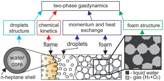
Figure 1.
Schematic of the numerical model and problem setup. The flame propagates downwards through the foam that decays into the droplets in the pre-flame zone (for convenience, the channel is shown horizontally. The top end is to the left, the bottom is to the right). The numerical model based on the two-phase gas dynamics includes submodels of momentum and heat exchange in the regions of foam and droplets, combustion kinetics, the structure of the emulsion droplet, and the non-uniform spatial distribution of liquid in the foam.
According to the previous studies of foams combustion, there is the following description of the basic mechanism of flame propagation through the foam. Foam decays into droplets in the pre-flame zone due to the thermal and dynamic impact on the foam from the flame front. Herewith, it should be noted that the foam, by its structure, consists of gas bubbles separated by thin liquid films intersected in the vertices called Plateau borders. When the foam decays, the thin films are corrupted first, while the thicker parts, Plateau borders, maintain their continuity. As a result, the liquid phase is decomposed into coarse droplets of a size equal to the Plateau border one. According to Kelvin’s law, the bubble diameter is related to the Plateau border size L as , so the radius of coarse droplets emerging from the foam decay can be estimated as . According to [19], the bubble size in the considered foam is estimated as m, and the diameter of the coarse droplets equals m. Herewith, the average distance between the droplets is also known and equals m. In such a way, the foam decays into the array of droplets suspended in the gas, hydrogen–oxygen mixture in the process of flame propagation. Further, after the foam is decayed in the pre-flame zone, the foaming gas is fed into the flame front together with the heptane vapor emitted from the surface of the droplets. The combustion propagates downwards in the form of the flame front.
Recently, we have proposed mathematical models suitable to predict both slow [36] and fast [27] combustion processes in foamed emulsions and hydrogen microfoams. Elaborated models provide a good agreement between the calculations and experimental data from [36] and [20]. They are based on the general two-phase hydrodynamic description with an account of:
- Gas–liquid multiphase interactions,
- Evaporation,
- Foam decay into droplets,
- Droplets fragmentation at high flow rates,
- Combustion.
According to the two-phase hydrodynamic model, the medium represents the blend of two continuums. Each continuum is characterized by its own mass density, velocity vector, and energy. The momentum transfer between phases is modeled with the use of Stokes-like force defining the velocities relaxation [37]. Herewith, the foam is treated as a much more resistant medium compared with the cloud of droplets. That is modeled via an empirical coefficient [37] found to be equal to 10 [27]. In view of this, the schematic presentation of the numerical model (Figure 1, dark blue box) indicates that there are two different models for momentum transfer in a two-phase medium in two regions.
When studying the phenomenon of flame acceleration [27], the process description is supplemented by the model of the foam structure presented in Figure 1 (green box). Dark grey zones marked as “liquid” indicate the regions of the higher mass density of the liquid phase and low density of the gas, while light zones marked as “gas” indicate the regions of lower density. As a result, when the foam decays, the dark regions, uniformly distributed in the space, model the coarse droplets formed in the process of foam decay. The proposed model reproduces the gaseous flame propagating through the combustible gas seeded with coarse liquid droplets acting on the flow as obstacles (regions with high resistance). Herewith, the liquid is evaporated from the surfaces of the droplets and dilutes the combustible gas with heptane and water vapors.
Heptane is a hydrocarbon characterized by a positive value of the entry coefficient, which is defined as [38] (here, is the surface tension of the aqueous solution of the surfactant, is the surface tension of the oil, is the surface tension at the water–oil interface). When the condition is satisfied, the hydrocarbon phase enters the water surface [38]. As a result, the heptane occurs to be distributed at the liquid–gas interface, and therefore the foam breaks up into droplets, which have a water core covered with a hydrocarbon shell (Figure 1, light blue box). In such a case, the heptane evaporates first and burns down in the flame front together with hydrogen, while the water vapors can be found only far behind the flame front. In the case of foamed emulsion without hydrogen, this effect exactly defines the natural separation between the zones of fuel combustion and the water evaporation with corresponding heat losses [39].
When modeling the combustion of combined fuels [40], it is important to take into account all the dominant reactions defining the interactions between the main components of the fuel (Figure 1, red box). In particular, when modeling any binary blend (e.g., methane/n-heptane [41]), one of the components displaces another at a certain content in the blend. That means that the pathways of the reaction change, and the features of the combined fuel combustion repeat the features intrinsic to the combustion of the predominant component. Given this, when modeling the combustion of hydrogen-containing blends, it is important to take into account the possible ways to influence the chain path of hydrogen oxidation. Thus, it is well known that hydrocarbons can adsorb free radicals and thus decelerate the chain reaction or even quench it. As a result, hydrocarbons sometimes are treated as promising inhibitors of a hydrogen explosion [34]. In this paper, a well-known contemporary kinetic mechanism from [42] is employed to model hydrogen combustion. This mechanism is completed with the reduced kinetic mechanism of heptane combustion [43] operating in a wide range of mixture compositions and thermodynamic states. It is important to note that the kinetic mechanism [43] includes the reactions involving the free radicals such as , and responsible for the chain combustion process both in the hydrogen and hydrocarbon oxidation process. The main focus of the work is aimed at the modes studied experimentally in [19], so the compositions of the foam correspond to those discussed in previous experiments. There stoichiometric and lean compounds of hydrogen–oxygen mixtures were considered, and the heptane was treated as an addition to hydrogen–oxygen. The volumetric content of heptane in the emulsion was varied up to 16 vol.%. Using the detailed kinetic model as a part of the two-phase gas-dynamic model allows a thorough analysis of the spatio-temporal evolution of the temperature field, as well as the fields of concentration of each chemical component, including active radicals.
The calculations are carried out for a two-dimensional problem setup similar to the one considered in [27]. Herewith, the conventional numerical technique called the “coarse particles method” is used. Previously it was widely exploited to solve various problems of gaseous and multiphase combustion see [44] and cites within. The numerical technique represents a finite-difference scheme with the second-order accuracy in space and first-order accuracy in time. The uniform computational mesh with the cell size m is used, which is in the resolution range according to the convergence tests previously carried out in [27]. Most of the calculations discussed below are carried out with the use of numerical domains consisting of 2–4 million numerical cells. The computational domain consists of the channel of 1 cm width and 24 cm length and the adjacent volume to the top from the channel where the combustion products are exhausted.
3. Results and Discussion
3.1. Flame Dynamics
First, let us consider the main features of non-steady flame behavior inside the tube filled with the combustible foamed emulsion. Figure 2 demonstrates the multidimensional (two-dimensional) flame front propagating downwards. As one can clearly see, the flame front is extremely corrugated. There are lots of small-scale structures in the background of the general shape of the flame elongated along the channel walls. That flame corrugation is due to the fact that the flame front is permanently subjected to small-scale perturbations originating from the coarse droplets interactions with the flame front. Such a permanent dynamic impact on the flame front causes a continuous increase in the area of the flame surface. Each perturbation of the flame surface gives rise to the gas-dynamic instability of the flame front, so the flame consumes the fresh medium faster. A larger flame area and its faster propagation in space define more frequent interactions of the flame with the droplets. That, in turn, leads to more intense development of the flame surface, etc. Therefore, there is a mechanism of positive feedback according to which the flame acceleration can be precisely described by exponential law . The increment is an intrinsic parameter of each foam. Thus, as one can see from Figure 3, occurs to be almost twice larger in the case of more reactive foam containing stoichiometric hydrogen–oxygen mixture as a foaming gas (Figure 3b) compared with the case of lean hydrogen–oxygen mixture (Figure 3a).
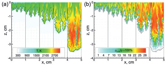
Figure 2.
Temperature (a) and mass fraction (b) fields in the vicinity of the flame front (black line) at subsequent time instants starting from 75 s with a time step of 30 s. The emulsion containing 0.5 vol.% of heptane is foamed with mixture. corresponds to the top open end of the channel.
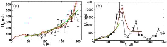
Figure 3.
History of the flame speed in the emulsions (a) containing 0.5 vol.% of heptane and foamed with mixture and (b) containing 0.5 vol.% of heptane and foamed with mixture. Red line—calculations (red region between red lines in frame (a)—divergence obtained from the series of calculations), signs connected with dotted line—experiment from [19], green line—exponential fit.
In some cases, especially when a stoichiometric hydrogen–oxygen mixture is used as a foaming gas (Figure 3b), the flame acceleration can lead to the transition to detonation. Herewith, the detonation wave occurs to be unstable when propagating through the foam, it decays, and further combustion propagates at a much lower speed (Figure 3b). As a result, the average combustion speed, in this case, occurs to be much lower than the detonation one. This mode was studied in detail previously in [20,27], where pure hydrogen–oxygen microfoam was considered.
When carrying out calculations of flame propagation through the foam according to the proposed model, it is useful to analyze how the choice of initial conditions (Figure 1) affects the solution. A series of three calculations with a different (random) initial distribution of bubbles is carried out to perform such an analysis. The discrepancy of the obtained results is denoted in Figure 3 by a red region between two red lines representing minimal and maximal values obtained numerically. As one can clearly see, the discrepancy is rather small and does not exceed the error of flame speed estimation based on the experimental data. That is due to the fact that the flame acceleration is driven mainly by the local effect of flame front perturbation by the coarse droplets. As a result, the flame evolution depends weakly on the particular spatial distribution of bubbles. The same feature was also illustrated in [27] by changing the width of the channel. It was shown that since the local effect plays a predominant role, there is no obvious dependence of the flame dynamics on the channel width.
When analyzing the experimental data obtained in [19], the average flame speed was introduced as an integral parameter characterizing the non-steady process of flame propagation through the channel filled with the foam. Here, a set of calculations with various foam compositions are carried out and analyzed together with the experimental points from [19]. Both sets of experimental and computed values are gathered in Figure 4. As one can see, the model used in the calculations reproduces experimental results quite well, at least on the qualitative level. Quantitatively, the combustion limits are not the same as in the experiment. Thus, for example, experiments show that the addition of 2.4 vol.% of heptane in the emulsion foamed with stoichiometric hydrogen–oxygen defines near-limit slow combustion mode, while numerical estimation of the combustion limit in the case of stoichiometric hydrogen–oxygen corresponds to ∼4.5 vol.% of heptane in the emulsion. In the case of lean hydrogen–oxygen, () the experiment shows that combustion quenches only at higher than 16 vol.% of heptane content in the emulsion. At the same time, the numerical estimation of the combustion limit is ∼9 vol.% of heptane in the emulsion. Nevertheless, all the main trends are quite close to the experimental ones. One can clearly observe the decrease in the average flame speed at reduced hydrogen content as well as the flame quenching with the increase in the heptane content. All these effects are closely related to the peculiarities of combustion kinetics in the combined multi-component fuel and are discussed in detail below. It is important to note that it is not clear that such a complex model can reproduce the experimental data well enough (at least at the qualitative level). At the same time, the validity of the proposed model, proven by comparison with experimental data, allows us to conclude that it is correct, at least on the qualitative level, to provide an interpretation of the combustion features intrinsic to the considered combined fuel with the use of the chosen kinetic model. Without a doubt, further development of experimental techniques and mathematical models is required for the comprehensive analysis of foamed emulsion combustion. This particular work is only one of the first steps.
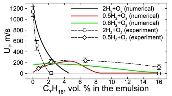
Figure 4.
Averaged flame speed dependence on the heptane content in the initial emulsion at various hydrogen content in the foaming gas mixture. Experimental data are taken from [19]. Error bars are estimated on the base of three independent tests with the same foam.
3.2. Mutual Effect of Hydrogen and Heptane in the Process of Foamed Emulsion Combustion
Now we consider the mutual effect of hydrogen and heptane in the process of foamed emulsion combustion. The experimental analysis [19], as well as the calculations, show that the heptane addition into the foam bubbled with stoichiometric hydrogen–oxygen mixture leads to the flame deceleration and its further quenching at a certain critical concentration of heptane (Figure 4). In the case of the lean hydrogen–oxygen mixture used as a foaming gas, the combustion limit extends while the dependence of the average flame speed on the heptane concentration demonstrates the ambiguous effect of heptane on the combustion (Figure 4). At low heptane content, the combustion mode occurs to be intensified compared with a combustion mode in the pure hydrogen microfoam. The inhibition effect is also observed but at relatively high heptane content.
According to the obtained results (Figure 4), there are two basic scenarios of flame evolution in a hydrogen/heptane blend. The first one concerns the case where the hydrogen content is high, and hydrogen–oxygen combustion is the primary process ( mixture). The second concerns the case with an excess of oxygen ( and mixtures) when the heptane oxidation kinetics proceeds along with hydrogen oxidation.
In the first case, hydrogen oxidation proceeds much faster than heptane oxidation. So, this case can be considered as hydrogen combustion in the presence of a small additive of heptane. The addition of heptane, in turn, causes the termination of the chain-branching process via the reduction of concentrations of active radicals , , and via reactions such as
The formation of alkyl radicals, such as , via the above-mentioned reactions and reactions such as
also provides the termination of the chain-branching process [34,45]. As a result, the heptane addition leads to the deceleration of the hydrogen oxidation process and the corresponding change in the overall flame dynamics. As a result, the flame is quenched, and the quenching takes place at a relatively low concentration of heptane in the emulsion (∼3–5 vol.%).
When speaking about the chemical pathways defining either intensification or termination of combustion kinetics, it is of paramount importance to understand in which reactions free radicals are involved since the birth and termination of such radicals define the particular pathway via which the reaction proceeds. Nowadays, most of the combustion features can be analyzed with the use of contemporary representations of the chemical kinetics of combustion. Thus, for example, the chemical addition of radicals into the combustion zone [46] is known to intensify the combustion since the chain-branching pathway is intensified. In the opposite case, excluding radicals from the reaction zone via chemical reactions with added active agents [47] defines the termination of the chain-branching process, and the combustion is inhibited. That behavior is similar to the intrinsic chain path termination in the combustion process [48]. Further, it is precisely this mechanism that is involved in hydrogen combustion inhibition via recombination when interacting with heptane molecules ().
At low hydrogen content and corresponding oxygen excess in the foaming gas, heptane oxidation proceeds along with hydrogen oxidation reactions. In such conditions, the flame dynamics are determined by the combustion of the heptane–hydrogen blend from the very beginning. Here, one can distinguish two stages in the process of flame propagation through the heptane-based emulsion foamed with the lean hydrogen–oxygen mixture. At the first stage, the flame propagates at a relatively low speed (the visible flame speed is not higher than ∼100 m/s, Figure 3a). As one can see from Figure 2, the combustion temperature at this early stage is rather low, less than 2000 K. Herewith, while the flame front is not so fast, the heptane has time to be evaporated from the surface of the emulsion droplets, and there is a substantial accumulation of heptane vapor in the pre-flame zone (see blue line on Figure 5b). The hydrogen–heptane blend occurs to be less reactive than the pure hydrogen–oxygen mixture (compare solid and dashed profiles in Figure 5), and the flame front in the case of hydrogen–heptane blend occurs to be widened compared with the case of hydrogen foam. Nevertheless, the flame accelerates via hydrodynamic mechanism discussed in Section 3.1. In the process of flame acceleration the temperature of the flame front increases, as is seen from the data presented in Figure 2a. Herewith, there is a certain steepening of the temperature profile (compare solid and dashed lines in Figure 6a) that indicates that the flame thickness decreases, and the hydrogen oxidation kinetics achieves an increasingly dominant role.

Figure 5.
Temperature (a) and active radicals ((a)—H and CO, (b)—HO, CH and CH) profiles in the vicinity of the flame front (). Dashed lines—hydrogen microfoam, mixture. Solid lines—foamed emulsion with vol.% of heptane in the emulsion foamed with mixture.
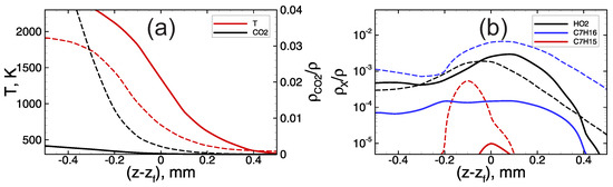
Figure 6.
Temperature (a) and active radicals ((a)—CO, (b)—HO, CH and CH) profiles in the vicinity of the flame front () in the foamed emulsion with vol.% of heptane in the emulsion, foaming gas— mixture. Dashed lines—first stage of slow flame propagation. Solid lines—second stage of fast flame propagation.
At a sufficiently high speed of flame propagation, the heptane has less time to be evaporated from the surface of the droplets in the pre-flame zone, and there is no significant accumulation of heptane vapor in the pre-flame zone (Figure 6b). At the same time, one can see (Figure 2b and Figure 6a) that the concentration of is extremely low behind the flame front. This indicates that there is no heptane combustion inside the flame front, and heptane burns down much later in the combustion products area.
The quenching of the flame in the case of the lean hydrogen–oxygen mixture takes place only at relatively high heptane content (Figure 4). Herewith, the quenching takes place at the early stage of slow flame propagation. In that case, a significant excess of heptane is observed in the pre-flame zone. Excessive heptane starts to play the role of inhibitor being involved in the reactions of chain termination mentioned above.
Summarizing the data presented above, one can distinguish three basic modes of the mutual effect of hydrogen and heptane in the process of foamed emulsion combustion. First of all, there is a mode where the heptane inhibits the hydrogen combustion, and this effect is pronounced in the case of a stoichiometric hydrogen–oxygen mixture. High-temperature combustion determines an intense heat flux from the flame front. That causes heptane evaporation, so heptane takes part in the reaction process on the scales of the flame front. Herewith, the combustion of the stoichiometric hydrogen–oxygen mixture can be quenched even at relatively low concentrations of heptane in the emulsion. The second mode is observed in the emulsions foamed with the lean hydrogen–oxygen mixtures. At an early stage of flame propagation, even at relatively low combustion temperature, the heptane has time to evaporate and accumulate in the pre-flame zone. Here, heptane also takes part in the oxidation reaction together with the hydrogen. In that case, the combustion of the hydrogen–heptane blend is observed. Each component can act as an inhibitor for the other (in different temperature ranges [49]), but both are engaged in the oxidation process. The third mode is realized at higher speeds of flame propagation. In that case, the heptane has no time to evaporate in the pre-flame zone. Thus, almost pure hydrogen combustion proceeds on the scales of the flame front, defining intense burning, flame acceleration, and even transition to detonation [19], as in the case of pure hydrogen-based microfoam [20].
4. Conclusions
In this paper, the combustion of combined fuel on the base of oil-in-water emulsion foamed with the hydrogen–oxygen mixture is studied numerically based on a two-phase hydrodynamic model, which demonstrates satisfactory validity when predicting experimentally observed features of foamed emulsion combustion based on the comparison of flame speed histories obtained experimentally and numerically. Combustible foam represents a promising type of reactor suitable for studying the aspects of combustion in complex blends containing liquid hydrocarbon fuels, gaseous fuels, and water. In particular, the mutual effect of hydrocarbon components and hydrogen on the combustion process is of paramount importance. The following possible modes of hydrogen–heptane blend combustion are obtained:
- Inhibition of hydrogen combustion by heptane via termination of chemical chain reactions. This mode is observed in the case of the stoichiometric hydrogen–oxygen mixture and causes the flame quenching at certain concentrations of heptane. The same mode can be expected in the case of rich hydrogen–oxygen mixtures.
- Joint combustion of hydrogen and heptane. This mode is observed in the case of lean hydrogen–oxygen mixtures with moderate heptane content in the combined fuel at low speeds of flame propagation (at the early stage).
- When the flame achieves high enough speed, it is shown that heptane has almost no time to be evaporated in the reaction zone, so the modes of fast hydrogen combustion are much less sensitive to the heptane addition into the system.
All these possible modes of hydrogen–heptane blend combustion in the presence of a liquid phase are not uniquely intrinsic to the considered combustible system (foamed emulsion). Close features can be observed when utilizing other combined fuels and can be used for safety solutions as well, where the understanding of the concentration limits and the effectiveness of inhibitors are in demand.
Author Contributions
Conceptualization, A.K.; methodology, A.K. and I.Y.; software, A.K. and I.Y.; validation, A.K.; formal analysis, A.K.; investigation, A.K. and I.Y.; resources, A.K.; data curation, I.Y.; writing—original draft preparation, A.K.; writing—review and editing, I.Y.; visualization, A.K.; supervision, A.K.; project administration, A.K.; funding acquisition, A.K. All authors have read and agreed to the published version of the manuscript.
Funding
This research received no external funding.
Institutional Review Board Statement
Not applicable.
Informed Consent Statement
Not applicable.
Data Availability Statement
The datasets generated and/or analysed during the current study are available from the corresponding author on reasonable request.
Acknowledgments
We are grateful to Boris Kichatov and Alexey Korshunov for fruitful discussions. We acknowledge high-performance computing support from the Joint Supercomputer Center of the Russian Academy of Sciences.
Conflicts of Interest
The authors declare no conflict of interest.
References
- Zhong, B.J.; Peng, H.S.; Zheng, D. The effect of different class of hydrocarbons on laminar flame speeds of three C7 fuels. Fuel 2018, 225, 225–229. [Google Scholar] [CrossRef]
- Mukhtar, M.N.A.; Hagos, F.Y.; Abdulah, A.A.; Karim, Z.A.A. Combustion characteristics of tri-fuel (diesel-ethanol-biodiesel) emulsion fuels in CI engine with micro-explosion phenomenon attributes. Fuel 2022, 312, 122933. [Google Scholar] [CrossRef]
- Tornatore, C.; Marchitto, L.; Teodosio, L.; Massoli, P. Performance and Emissions of a Spark Ignition Engine Fueled with Water-in-Gasoline Emulsion Produced through Micro-Channels Emulsification. Appl. Sci. 2021, 11, 9453. [Google Scholar] [CrossRef]
- Park, J.; Oh, J. Study on the characteristics of performance, combustion, and emissions for a diesel water emulsion fuel on a combustion visualization engine and a commercial diesel engine. Fuel 2022, 311, 122520. [Google Scholar] [CrossRef]
- Romanov, D.S.; Vershinina, K.Y.; Dorokhov, V.V.; Strizhak, P.A. Rheology, ignition, and combustion performance of coal-water slurries: Influence of sequence and methods of mixing. Fuel 2022, 322, 124294. [Google Scholar] [CrossRef]
- Glushkov, D.; Paushkina, K.; Vershinina, K. Slagging Characteristics of a Steam Boiler Furnace with Flare Combustion of Solid Fuel When Switching to Composite Slurry Fuel. Appl. Sci. 2023, 13, 434. [Google Scholar] [CrossRef]
- Qian, L.; Wan, J.; Qian, Y.; Sun, Y.; Zhuang, Y. Experimental investigation of water injection and spark timing effects on combustion and emissions of a hybrid hydrogen-gasoline engine. Fuel 2022, 322, 124051. [Google Scholar] [CrossRef]
- Sun, X.; Ning, J.; Liang, X.; Jing, G.; Chen, Y.; Chen, G. Effect of direct water injection on combustion and emissions characteristics of marine diesel engines. Fuel 2022, 309, 122213. [Google Scholar] [CrossRef]
- Mariani, A.; Unich, A.; Minale, M. Combustion of hydrogen enriched methane and biogases containing hydrogen in a controlled auto-ignition engine. Appl. Sci. 2018, 8, 2667. [Google Scholar] [CrossRef]
- Abe, J.; Popoola, A.; Ajenifuja, E.; Popoola, O. Hydrogen energy, economy and storage: Review and recommendation. Int. J. Hydrogen Energy 2019, 44, 15072–15086. [Google Scholar] [CrossRef]
- Li, C.; Wang, Y.; Jia, B.; Zhang, Z.; Roskilly, A. Numerical Investigation on NOx Emission of a Hydrogen-Fuelled Dual-Cylinder Free-Piston Engine. Appl. Sci. 2023, 13, 1410. [Google Scholar] [CrossRef]
- Taghavifar, H.; Anvari, S.; Parvishi, A. Benchmarking of water injection in a hydrogen-fueled diesel engine to reduce emissions. Int. J. Hydrogen Energy 2017, 42, 11962–11975. [Google Scholar] [CrossRef]
- Huo, M.; Lin, S.; Liu, H.; Lee, C.f.F. Study on the spray and combustion characteristics of water–emulsified diesel. Fuel 2014, 123, 218–229. [Google Scholar] [CrossRef]
- Feng, X.; Ren, J.; Pu, M.; Chen, B.; Bi, M. Suppression effect of ultra-fine water mist on methane-coal dust hybrid explosion. Powder Technol. 2022, 406, 117590. [Google Scholar] [CrossRef]
- Wang, F.; Yu, M.; Wen, X.; Deng, H.; Pei, B. Suppression of methane/air explosion in pipeline by water mist. J. Loss Prev. Process. Ind. 2017, 49, 791–796. [Google Scholar] [CrossRef]
- Yakovenko, I.; Kiverin, A. Intensification mechanisms of the lean hydrogen-air combustion via addition of suspended micro-droplets of water. Int. J. Hydrogen Energy 2021, 46, 1259–1272. [Google Scholar] [CrossRef]
- Kichatov, B.; Korshunov, A.; Kiverin, A.; Son, E. Foamed emulsion—Fuel on the base of water-saturated oils. Fuel 2017, 203, 261–268. [Google Scholar] [CrossRef]
- Kichatov, B.; Korshunov, A.; Kiverin, A.; Medvetskaya, N. Combustion of foamed emulsion prepared via bubbling of oxygen-nitrogen gaseous mixture through the oil-in-water emulsion. Fuel Process. Technol. 2019, 186, 25–34. [Google Scholar] [CrossRef]
- Kichatov, B.; Korshunov, A.; Gubernov, V.; Kiverin, A.; Yakovenko, I. Combustion of heptane-in-water emulsion foamed with hydrogen-oxygen mixture. Fuel Process. Technol. 2020, 198, 106230. [Google Scholar] [CrossRef]
- Kichatov, B.; Korshunov, A.; Kiverin, A.; Yakovenko, I.; Gubernov, V.; Khomik, S.V.; Medvedev, S.P. Detonation in the hydrogen-oxygen microfoam on the aqueous base. Int. J. Hydrogen Energy 2019, 44, 31567–31578. [Google Scholar] [CrossRef]
- Xu, C.; Wang, Q.; Li, X.; Liu, K.; Liu, W.; Oppong, F.; Sun, Z.Y. Effect of hydrogen addition on the laminar burning velocity of n-decane/air mixtures: Experimental and numerical study. Int. J. Hydrogen Energy 2022, 47, 19263–19274. [Google Scholar] [CrossRef]
- Pukalskas, S.; Kriaučiūnas, D.; Rimkus, A.; Przybyła, G.; Droździel, P.; Barta, D. Effect of hydrogen addition on the energetic and ecologic parameters of an si engine fueled by biogas. Appl. Sci. 2021, 11, 742. [Google Scholar] [CrossRef]
- Yin, Y.; Medwell, P.R.; Gee, A.J.; Foo, K.K.; Dally, B.B. Fundamental insights into the effect of blending hydrogen flames with sooting biofuels. Fuel 2023, 331, 125618. [Google Scholar] [CrossRef]
- Babkin, V.; Kakutkina, N.; Zamaschikov, V. Characteristics of water-base foam combustion. Symp. (Int.) Combust. 1994, 25, 1627–1634. [Google Scholar] [CrossRef]
- Saint-Cloud, J.P.; Peraldi, O. Detonations in Explosive Foams. Prog. Astronaut. Aeronaut. 1984, 94, 302–308. [Google Scholar] [CrossRef]
- Subbotin, V.; Usol’tsev, S. Study of the mechanism of the transfer of gaseous detonation through films of liquid. Combust. Explos. Shock Waves 1984, 20, 224–230. [Google Scholar] [CrossRef]
- Kiverin, A.; Yakovenko, I. Numerical Modeling of Combustion and Detonation in Aqueous Foams. Energies 2021, 14, 6233. [Google Scholar] [CrossRef]
- Nicoli, C.; Haldenwang, P.; Denet, B. Darrieus–Landau instability of premixed flames enhanced by fuel droplets. Combust. Theory Model. 2017, 21, 630–645. [Google Scholar] [CrossRef]
- Nicoli, C.; Haldenwang, P.; Denet, B. Premixed flame dynamics in presence of mist. Combust. Sci. Technol. 2019, 191, 197–207. [Google Scholar] [CrossRef]
- Sánchez, A.L.; Williams, F.A. Recent advances in understanding of flammability characteristics of hydrogen. Prog. Energy Combust. Sci. 2014, 41, 1–55. [Google Scholar] [CrossRef]
- Yu, G.; Law, C.; Wu, C. Laminar flame speeds of hydrocarbon + air mixtures with hydrogen addition. Combust. Flame 1986, 63, 339–347. [Google Scholar] [CrossRef]
- Halter, F.; Chauveau, C.; Djebaïli-Chaumeix, N.; Gökalp, I. Characterization of the effects of pressure and hydrogen concentration on laminar burning velocities of methane–hydrogen–air mixtures. Proc. Combust. Inst. 2005, 30, 201–208. [Google Scholar] [CrossRef]
- Aggarwal, S.; Awomolo, O.; Akber, K. Ignition characteristics of heptane–hydrogen and heptane–methane fuel blends at elevated pressures. Int. J. Hydrogen Energy 2011, 36, 15392–15402. [Google Scholar] [CrossRef]
- Azatyan, V.V.; Prokopenko, V.M.; Chapysheva, N.V.; Abramov, S.K. Difference in the Mechanisms of the Inhibition of Hydrogen Combustion in the Deflagration and Detonation Modes. Russ. J. Phys. Chem. B 2018, 12, 103–107. [Google Scholar] [CrossRef]
- Li, Y.; Bi, M.; Li, B.; Zhou, Y.; Gao, W. Effects of hydrogen and initial pressure on flame characteristics and explosion pressure of methane/hydrogen fuels. Fuel 2018, 233, 269–282. [Google Scholar] [CrossRef]
- Kiverin, A.; Yakovenko, I.; Kichatov, B.; Korshunov, A. Ignition and non-stationary combustion of the foamed heptane-in-water emulsion: Experimental and numerical analysis. Fuel 2022, 320, 123824. [Google Scholar] [CrossRef]
- Faure, S.; Ghidaglia, J.M. Violent flows in aqueous foams I: Physical and numerical models. Eur. J. Mech.—B/Fluids 2011, 30, 341–359. [Google Scholar] [CrossRef]
- Aveyard, R.; Binks, B.P.; Fletcher, P.D.; Peck, T.G.; Garrett, P.R. Entry and spreading of alkane drops at the air/surfactant solution interface in relation to foam and soap film stability. J. Chem. Soc. Faraday Trans. 1993, 89, 4313–4321. [Google Scholar] [CrossRef]
- Yakovenko, I.; Kiverin, A.; Korshunov, A.; Kichatov, B. Combustion Limits of Foamed Emulsions with High Water Content. Tech. Phys. Lett. 2019, 45, 1241–1244. [Google Scholar] [CrossRef]
- Xu, L.; Chang, Y.; Treacy, M.; Zhou, Y.; Jia, M.; Bai, X.S. A skeletal chemical kinetic mechanism for ammonia/n-heptane combustion. Fuel 2023, 331, 125830. [Google Scholar] [CrossRef]
- Song, C.; Liang, J.; Zhang, Z.; Li, G.; Zhang, C. Interpretation of role of methane in low-temperature oxidation processes of methane/n-heptane mixtures. Fuel 2022, 328, 125373. [Google Scholar] [CrossRef]
- Kéromnès, A.; Metcalfe, W.K.; Heufer, K.A.; Donohoe, N.; Das, A.K.; Sung, C.J.; Herzler, J.; Naumann, C.; Griebel, P.; Mathieu, O.; et al. An experimental and detailed chemical kinetic modeling study of hydrogen and syngas mixture oxidation at elevated pressures. Combust. Flame 2013, 160, 995–1011. [Google Scholar] [CrossRef]
- Maroteaux, F.; Noel, L. Development of a reduced n-heptane oxidation mechanism for HCCI combustion modeling. Combust. Flame 2006, 146, 246–267. [Google Scholar] [CrossRef]
- Ivanov, M.F.; Kiverin, A.D.; Liberman, M.A. Ignition of deflagration and detonation ahead of the flame due to radiative preheating of suspended micro particles. Combust. Flame 2015, 162, 3612–3621. [Google Scholar] [CrossRef]
- Emami, S.D.; Kasmani, R.M.; Hamid, M.D.; Che Hassan, C.R.; Mokhtar, K.M. Kinetic and dynamic analysis of hydrogen-enrichment mixtures in combustor systems—A review paper. Renew. Sustain. Energy Rev. 2016, 62, 1072–1082. [Google Scholar] [CrossRef]
- Manias, D.M.; Rabbani, S.; Kyritsis, D.C.; Goussis, D.A. The effect of fuel additives on the autoignition dynamics of rich methanol/air mixtures. Fuel 2022, 323, 124275. [Google Scholar] [CrossRef]
- Xu, H.; Yao, C.; Xu, G. Chemical kinetic mechanism and a skeletal model for oxidation of n-heptane/methanol fuel blends. Fuel 2012, 93, 625–631. [Google Scholar] [CrossRef]
- Zhong, F.; Zheng, L.; Zhang, J.; Wang, X.; Shi, Z.; Miao, Y.; Wang, J. Comparison of the premixed flame dynamics of CH4/O2/CO2 mixtures in closed and half-open ducts. Fuel 2022, 323, 124326. [Google Scholar] [CrossRef]
- Frolov, S.; Medvedev, S.; Basevich, V.; Frolov, F. Self-ignition of hydrocarbon–hydrogen–air mixtures. Int. J. Hydrogen Energy 2013, 38, 4177–4184. [Google Scholar] [CrossRef]


Disclaimer/Publisher’s Note: The statements, opinions and data contained in all publications are solely those of the individual author(s) and contributor(s) and not of MDPI and/or the editor(s). MDPI and/or the editor(s) disclaim responsibility for any injury to people or property resulting from any ideas, methods, instructions or products referred to in the content. |
© 2023 by the authors. Licensee MDPI, Basel, Switzerland. This article is an open access article distributed under the terms and conditions of the Creative Commons Attribution (CC BY) license (https://creativecommons.org/licenses/by/4.0/).