Article

Calculation Method of Stable Bearing Capacity of Fastener-Type Steel Pipe Formwork Support Upright Rod

School of Civil & Architecture Engineering, Xi’an Technological University, Xi’an 710021, China
*
Author to whom correspondence should be addressed.
Appl. Sci. 2023, 13(8), 4838; https://doi.org/10.3390/app13084838
Submission received: 9 March 2023 / Revised: 10 April 2023 / Accepted: 10 April 2023 / Published: 12 April 2023
(This article belongs to the Section Civil Engineering)

Abstract

:
In this paper, the torsional moment of the right-angle fastener bolt is taken as the main research parameter, and the torsional stiffness performance of the right-angle fastener under different working conditions is studied experimentally. By establishing the moment–rotation relationship model of the node, the mechanical performance and rotation characteristics of the semirigid connection of the node are studied. According to the joint stiffness value determined by the experimental study and the theory of semirigid connection frame with lateral displacement, the calculation formulas of the stiffness correction coefficient α u of the transverse bar and the constraint coefficient K at the end of the vertical bar are derived, and the effective length coefficient μ of the vertical bar and the theoretical value of the stable bearing capacity of the vertical bar under different working conditions are given. Compared with the current standard values, it is found that the theoretical calculation results of the percentage increase of the stable bearing capacity of the vertical bar are 3 to 4 times larger than the standard calculation results when the step distance is reduced. The theoretical calculation method can better consider the semirigid characteristics of the joint and the influence of adjacent members on the stable bearing capacity of the vertical bar.

1. Introduction

With the vigorous development of China’s infrastructure construction, fastener-type steel pipe formwork support is the most widely used formwork support system, which is often used in the construction of concrete structures, steel structure construction, and installation, etc. It has the most direct impact on the construction efficiency, engineering quality, and engineering safety of construction projects. The fastener-type steel pipe formwork support not only bears the weight of the formwork and the component during the pouring and curing period, but also bears the external load and maintains its own stability. Therefore, it is of great significance to study the calculation method of the stable bearing capacity of the fastener-type steel pipe formwork support [1,2].
Many experts and scholars have rich experience in studying the stability bearing capacity of the vertical bar [3,4,5,6,7,8,9,10]. Some scholars have their own unique views on numerical simulation [11,12,13]. By considering the factors affecting the mechanical properties of fasteners, Jia Li et al. [14,15] pointed out that the antisliding bearing capacity of new fasteners is higher than that of old fasteners, and gave the antisliding force values of different fastener connection forms. Cheng Haibin [16], in order to study the relationship between the torque of the fastener bolt and the axial force of the bolt rod, carried out a numerical simulation of the bearing capacity of the scaffold under different parameters. It is pointed out that in the case of considering the initial defects of the scaffold, the bearing capacity of the scaffold will decrease with the increase of the length of the vertical rod. Xie Xiangyang et al. [17] used the control variable method to simulate the bearing capacity of scaffold, and obtained the action mechanism of different constraints on scaffold members. On this basis, a multiparameter simulation method of semirigid joints was proposed. Lin Hongyuan et al. [18] took the double-row scaffold as the research object, and established the double-row scaffold model by using the finite element software. By considering the number of right-angle fastener failures and the location of failure, the bearing capacity of the scaffold was simulated and analyzed. It is pointed out that the bearing capacity of the scaffold decreases with the increase of the number of fastener failures. Saritas et al. [19] proposed a beam element model considering local semirigid connection by considering the semirigid characteristics of beam–column joints, and analyzed the performance of steel structure joints. In order to truly represent the hysteretic behavior of the joints under cyclic loading, the hysteretic model of the joints is established to analyze the energy consumption effect of the semirigid joints on the structure. The influence of semirigid joints on the bearing capacity of steel structure is verified by comparison with numerical simulation and experimental results. Zhang [20] compared the second-order inelastic analysis methods in different national steel structure codes, used different analysis methods to analyze the scaffolding, and pointed out the shortcomings of different analysis methods. Pieńko et al. [21] numerically simulated the bearing capacity of scaffold joints by considering the nonlinearity of joint materials and the interaction between joint elements. The analysis results can be used to calculate the ultimate bearing capacity of the joints. Compared with the traditional test method, the numerical simulation can accurately analyze the bearing capacity of the scaffold joints. Robert [22] analyzed the research progress of scaffold structure in the past 40 years. Combined with the reliability study of scaffold collapse, the influence of vertical load, wind load, and seismic load on the stability of scaffold structure was analyzed. It is pointed out that the influence of joint relaxation should be considered in the design of scaffold code, and it is suggested that the safety factor of vertical load should be adjusted to 2.0. Through scaffold monitoring and accident investigation, it is found that most accidents are caused by inadequate on-site supervision and irregular design.
According to the production safety accident data released by the Ministry of Housing and Urban–Rural Development, in 2019, there were 773 production safety accidents and 904 deaths in China’s housing and municipal engineering. Compared with the previous year, the number of accidents increased by 5.31% and the number of deaths increased by 7.62% [23]. The main reason is that the calculation method of the stability bearing capacity of the fastener-type steel pipe formwork support is not perfect, which leads to the deviation of the calculated stability bearing capacity of the vertical bar from the reality, resulting in frequent collapse accidents of the formwork support [24]. The current specification ‘Safety Technical Specification for Steel Tubular Scaffold with Fasteners in Building Construction’ (JGJ130-2011) [25] is the most widely used specification basis for the design and calculation of the stability bearing capacity of the steel tubular scaffold with fasteners by the construction unit. However, it is not reasonable to refer to the stability calculation theory of the single and double-row scaffold poles for the calculation of the stability bearing capacity of the steel tubular scaffold with fasteners. When the current specification is used to calculate the stability bearing capacity of the steel tubular scaffold with fasteners, the influence of the joint stiffness on the stability bearing capacity of the scaffold cannot be considered well, and the joint stiffness of the frame is related to the torsional moment of the right-angle fastener bolt in engineering practice. Therefore, it is necessary to study the calculation method of stable bearing capacity of fastener-type steel pipe formwork support.
In this paper, the torsional stiffness performance of right-angle fasteners is studied experimentally. The rotational stiffness of the joints is determined by the moment–rotation curve of the joints, which provides parameters for the numerical simulation and stable bearing capacity calculation of the fastener-type steel tube formwork support. Based on the theory of semirigid connection frame with lateral displacement, the formula of effective length coefficient μ of the vertical bar is derived. The theoretical calculation formula and the current standard method are used to calculate the stable bearing capacity of the formwork support. Finally, compared with the numerical simulation results, the calculation method of the stable bearing capacity of the fastener steel pipe formwork support is given.

2. Material and Methods

2.1. Torsional Stiffness Performance Test of Right Angle Fastener

2.1.1. Test Program

In this paper, the torsional stiffness performance of right-angle fasteners is studied experimentally. The rotational stiffness of the joints under different torsional moments of right-angle fastener bolts is measured by experiments. The test results are fitted to obtain the moment–rotation relationship model of the joints under different working conditions, which provides a basis for the calculation and numerical simulation of the stable bearing capacity of the fastener-type steel tube formwork support.
Referring to the current national standard ‘Steel Pipe Scaffolding Fasteners’ (GB15831-2006) [26], the test method of torsional stiffness performance of right-angle fasteners is as follows: select the steel pipe with a transverse rod length of 2 m, apply load P on the transverse rod at a distance of 1 m from the center, and measure the displacement value f of the transverse rod at a distance of 1 m from the center at the load-free end. The existing standard weights in the laboratory are used for step-by-step loading. The bending moments applied to the right-angle fastener nodes are 100 N·m, 200 N·m, 300 N·m, 400 N·m, 500 N·m, 600 N·m, 700 N·m, 800 N·m, 900 N·m, and 1000 N·m, respectively. Details of test parameters are shown in Table 1.

2.1.2. Testing Apparatus

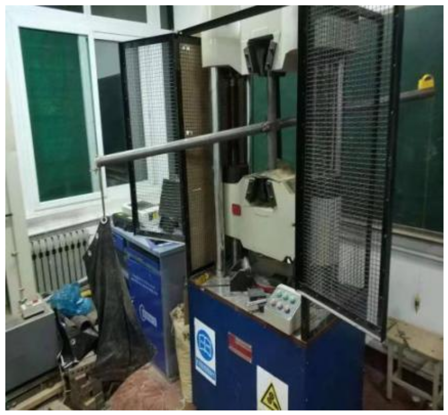
Microcomputer controlled electrohydraulic servo universal testing machine, torque wrench, digital vernier caliper, standard code removing, and the parameters of the test instrument are shown in Table 2, and the test device is shown in Figure 1. The top and bottom of the vertical rod are fixed by the upper and lower clamping clamps of the universal testing machine, and the horizontal rod and the vertical rod are connected by the right-angle fastener.
The torque wrench is used to tighten the bolt to ensure that the torsional moment of the fastener meets the requirements. The torsional moments of the right-angle fasteners in each group of tests are 20 N·m, 30 N·m, 40 N·m, 50 N·m, and 60 N·m, respectively.

2.1.3. Test Loading Method

A crossbar with a length of 2 m is selected. The vertical bar and the crossbar are connected by right-angle fasteners, and the right-angle fastener is set in the middle position of the crossbar. The force is applied at one end of the crossbar with every 100 N until the force is applied to 1000 N, and the vertical displacement value f of the crossbar is recorded after each force is applied. The test loading method is shown in Figure 2.

2.1.4. Test Data Results

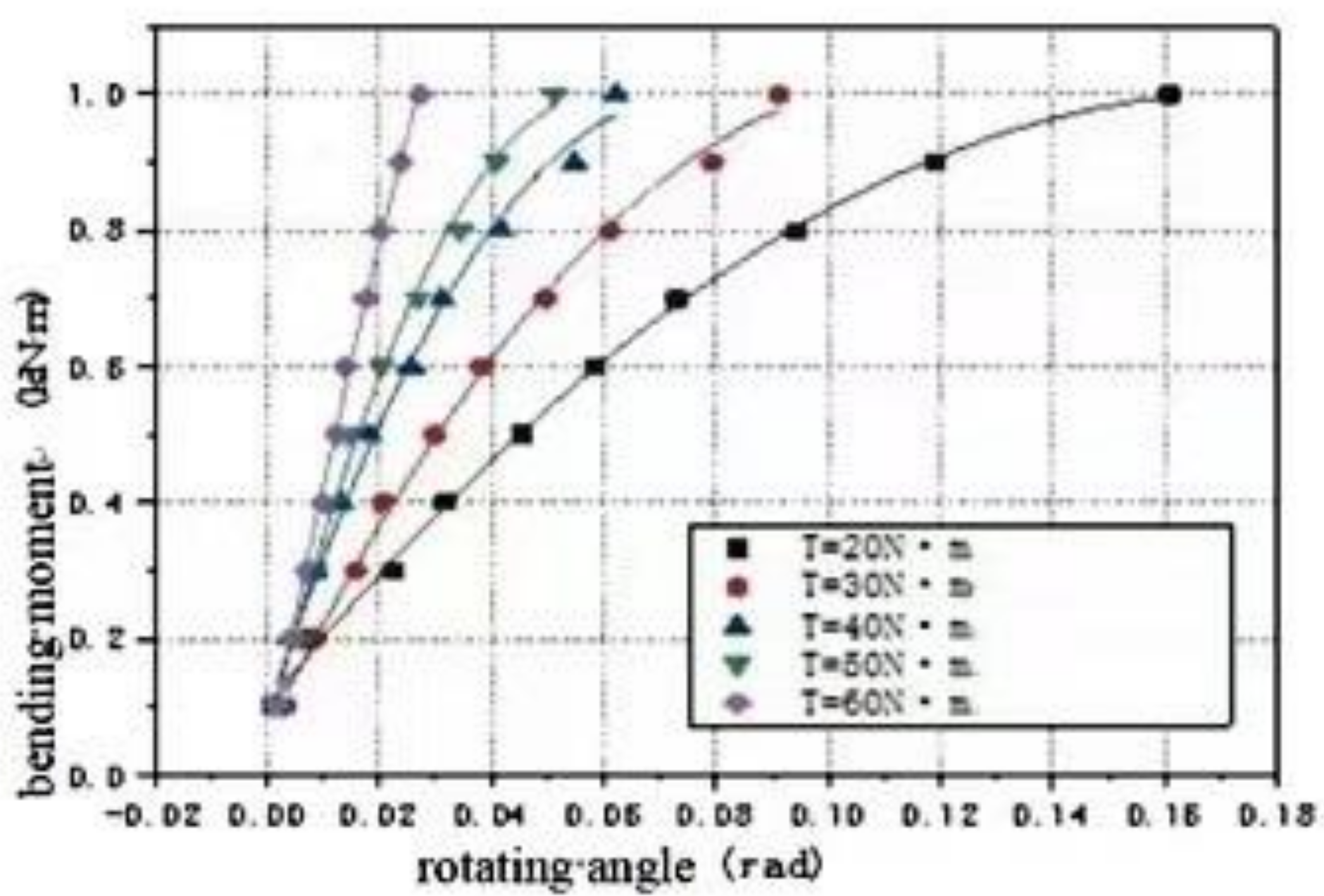
Using the mapping software, the obtained data is imported into the software to obtain a scatter plot. The quadratic function model is y = A + B 1 x + B 2 x 2 ;   A , B 1 ,   and   B 2 are undetermined coefficients, and the data of the torsional moment of the right-angle fastener bolt are 20 N·m, 30 N·m, 40 N·m, 50 N·m, and 60 N·m, respectively. The quadratic function formula of the test fitting is shown in Table 3, and the initial point tangent slope of the quadratic function is taken as the initial stiffness value of the fastener node. The bending moment–rotation curve of the joint under the same torsional moment of the right-angle fastener bolt in the test is obtained, as shown in Figure 3.

2.2. Semirigid Connection Frame Theory with Lateral Displacement

Usually, the fastener-type steel pipe formwork support is not set around the wall, and the lateral stiffness of the frame is small. When the fastener-type steel pipe formwork support is subjected to load, the frame will have a certain lateral displacement. Therefore, the analysis of the stable bearing capacity of the fastener-type steel pipe formwork support should refer to the theory of lateral semirigid connection frame [27].

2.2.1. Theoretical Calculated Length Factor for Frames with Laterally Shifted Semirigid Connections
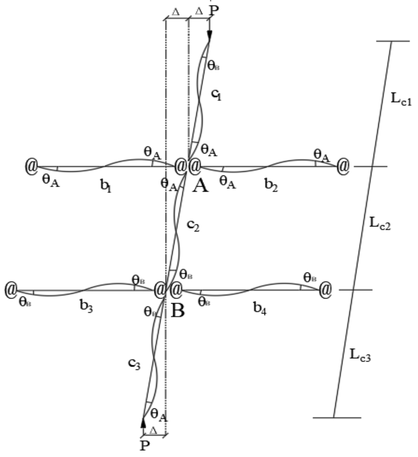
Wang Jingfeng [28] derived the Formula (1) for the calculated length factor of the semirigid frame column using the three-story frame model with lateral shift, and the three-story frame model with lateral shift is shown in Figure 4.
Figure 4. Three-layer frame model with lateral displacement.
Applsci 13 04838 g004
36 K 1 K 2 π μ 2 sin π μ + 6 K 1 + K 2 π μ · cos π μ = 0
K 1 = A α u E I b L b A E I c L c
K 2 = B α u E I b L b B E I c L c
In the formula:
  • K 1 —Upper end constraint coefficient of frame column with lateral displacement considering semirigid joints
  • K 2 —Constraint coefficient of lower end of frame column with lateral displacement considering semirigid joints
  • E I b —Bending stiffness of beam section
  • L b —Beam length
  • E I c —Bending stiffness of column section
  • L c —Column length
  • α u —Stiffness correction coefficient of frame beam with lateral displacement
Through the Formula (1), it can be seen that the effective length coefficient μ of the frame column is related to the constraint coefficients K 1 and K 2 , and the constraint coefficient is obtained by modifying the stiffness at both ends of the beam. Therefore, the accuracy of the beam end stiffness correction is the key to considering the semirigid characteristics of the joint. For the convenience of calculation, the effective length coefficient μ Formula (4) of the lateral frame column in China’s ‘Steel Structure Design Standard’ (GB50017-2017) [29] can be used to calculate:
μ = 7.5 K 1 K 2 + 4 K 1 + K 2 + 1.52 7.5 K 1 K 2 + K 1 + K 2

2.2.2. Consider the Node Semirigid Crossbar Stiffness Coefficient Correction

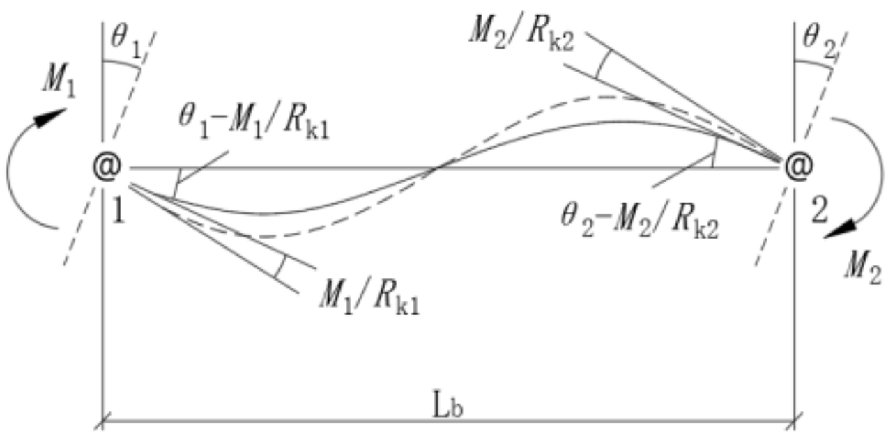
As shown in Figure 5, the two ends are semirigidly restrained with lateral shift of the crossbar, L b is the length of the crossbar, θ 1 and θ 2 are the turning angles of the two ends of the crossbar, and R k 1 and R k 2 are the turning stiffness of the crossbar nodes. Under the action of end moments M 1 and M 2 , the relative turning angles of the left and right ends of the crossbar are θ 1 = M 1 R k 1 and θ 2 = M 2 R k 2 , respectively.
Angle-displacement equation:
M 1 = E I b L b R * 4 + 12 E I b L b R k 2 θ 1 + 2 θ 2
M 2 = E I b L b R * 4 + 12 E I b L b R k 1 θ 2 + 2 θ 1
In the formula:
R * = 1 + 4 E I b L b R k 1 1 + 4 E I b L b R k 2 E I b L b 2 4 R k 1 R k 2
For the formwork bracket with lateral shift, the crossbar produces the same direction of turning angle, so the crossbar end moment M 1 is:
M 1 = α u 6 E I b L b θ 1
In the formula:
α u = 1 + 2 E I b L b R k 2 / R *
α u indicates the stiffness correction coefficient of the crossbar of the formwork bracket with a side-shift semirigid connection.

2.2.3. Calculation of Stable Bearing Capacity of Vertical Bar Based on Theory of Semirigid Connection Frame with Lateral Displacement

Through the theoretical study of the semirigid connection frame with lateral displacement, it is found that the effective length coefficient of the vertical bar of the fastener-type steel pipe formwork support is obtained according to the constraint coefficient of the upper and lower ends of the vertical bar. Therefore, the semirigid characteristics of the formwork support joint are considered by modifying the end stiffness of the transverse bar in the formwork support. In the derivation of the effective length coefficient of the vertical rod of the fastener-type steel pipe formwork support, there are the following assumptions: (1) Simultaneous buckling of the neutral rod on the same layer; (2) The rotation angles at both ends of the horizontal bar are equal; that is, the rotational stiffness at both ends of the horizontal bar is R k 1 = R k 2 , and the rotational stiffness at both ends of the horizontal bar is the rotational stiffness of the right angle fastener R k ; (3) The axial force of the bar is very small and can be ignored. From Formulas (7) and (9), the calculation formula (10) of the stiffness correction coefficient α u of the bar can be obtained.
α u = 1 + 2 E I L b R k 1 + 4 E I L b R k 2 E I L b 2 4 R k 2
  • E I —Bending stiffness of steel tube
  • R k —Rotational stiffness of right angle fastener
  • L b —Lag spacing
Q235 steel pipe is used in the vertical and horizontal rods of the fastener-type steel pipe formwork support; that is, the bending stiffness E I of the vertical rod and the horizontal rod is the same. The Formula (2) and (3) are simplified to obtain the constraint coefficient K formula (11).
K = α u L c L b
  • L c —Extension
  • L b —Lag spacing
The effective length coefficient μ of the pole is calculated by the simplified Formula (12):
μ = 7.5 K 2 + 8 K + 1.52 7.5 K 2 + 2 K
The stability of the pole under different node stiffness values is calculated. The Φ48.3 × 3.6 steel pipe with modulus of elasticity E = 2.06 × 10⁵ and I = 12.71 cm4 is used, the crossbar stiffness correction coefficient α u can be obtained according to Formulas (7) and (9), the end restraint coefficient of the upright can be obtained according to Formulas (2) and (3), the calculated length coefficient μ of the upright can be obtained by substituting into Formula (12), and finally the stable load capacity of the upright can be obtained according to the Euler formula F = π2EI/μ2l2. The theoretical value of the load bearing capacity, the erection parameters, and calculation results of the frame are shown in Table 4.
According to the experimental results of the torsional stiffness performance of the right-angle fastener, when the bending moment of the right-angle fastener is 0.8 kN·m, the bending moment–rotation curve of each group has an obvious gentle trend, the tangent slope of the curve becomes smaller, and the stiffness value of the joint is obviously reduced. At this time, the torque of the right-angle fastener node is too large, and the deformation of the right-angle fastener is large. Therefore, it is safe to take the slope of the corresponding curve when the bending moment of the right-angle fastener is 0.8 kN·m as the node stiffness value [30], and calculate when the torsional moment of the right-angle fastener bolt is 40 N·m. At this time, the fastener angle is 0.04 rad.
The calculation process is as follows:
R k = M = 2 × 164.08 θ + 24.35 = 11.27 kN·m/rad
R k —Torsional stiffness of right-angle fastener
Therefore, in the calculation, the stiffness value of the joint is substituted into the Formula (10) to obtain the stiffness correction coefficient α u of the crossbar, then substituted into the Formula (11) to obtain the constraint coefficient K at the end of the vertical bar, and finally substituted μ into the Formula (12). The stability bearing capacity of the vertical rod under different working conditions is calculated by Euler formula F = π2 EI/μ2l2, as shown in Table 5 and Table 6.

2.3. Calculation of the Stable Bearing Capacity of the Current Specification Uprights

2.3.1. Stability Calculation Formula of Pole

The current specification “Safety Technical Specification for Fastener Type Steel Pipe Scaffolding for Building Construction” (JGJ130-2011) shall meet the following formula requirements for the stability of the neutral rod:
When wind load is not combined:
N φ A f
When combining wind loads:
N φ A + M W W f
In the formula:
  • N—Calculate the design value of the axial force of the vertical rod section;
  • φ—The stability coefficient of the axially compressed rod, according to the length-to-slend ratio λ, is taken from the specification;
  • A—Cross-sectional area of uprights;
  • MW—Calculate the bending moment of the vertical pole section generated by the design value of wind load;
  • f—Design value of compressive strength of steel, f = 205 N/mm2.
The calculated length of the fastening type steel pipe formwork bracket uprights should be calculated according to the following formula, taking the most unfavorable value of the overall stability calculation results:
Top riser section:
l 0 = k μ 1 h + 2 a
Non-top riser section:
l 0 = k μ 2 h
In the formula:
  • k—Calculation of length addition factor;
  • h—Pace;
  • a—The length of the vertical rod extending from the center line of the top-level horizontal rod to the support point;
  • μ1, μ2—Calculated length coefficient of a single pole considering the overall stability of the frame.

2.3.2. Calculation Formula for Pole Stability

Take a fastener-type steel pipe bracket of 8 m height as an example: using Φ48.3 × 3.6 steel pipe, the number of span in longitudinal and transverse directions is 5, the top extension distance of the upright rod is a = 0.2 m, and the scissor brace is an ordinary type structure; the stable bearing capacity of the upright rod is calculated according to the formula for calculating the stability of the full hall support frame upright rod in the current specification, and the calculation results are shown in Table 7.

2.4. Finite Element Analysis Modeling

2.4.1. Material Parameters and Section Geometry Properties

The current specification “Safety Technical Specification for Fastening Steel Pipe Scaffolding for Building Construction” (JGJ130-2011) requires that the steel pipe used for fastening steel pipe formwork supports is Q235 steel, and the material parameters and cross-sectional geometric characteristics of the steel pipe are shown in Table 8 and Table 9.

2.4.2. Basic Assumptions of the Computational Model

Using finite element software to model the fastener type steel pipe formwork support with the following assumptions [31]:
(1)
The connection between the frame and the ground is considered as articulated and the uneven settlement of the foundation is not considered.
(2)
The effects of wind and earthquake loads on the frame body are not considered.
(3)
Ignore the effect of axial deviation between the frame bars, assuming that all bars in the frame are axially in the same frame plane.
(4)
The connection of scissor braces to other bars is considered as hinged.
(5)
The vertical load is uniformly applied to the top of each rod, and the load is not eccentric.

2.4.3. Finite Element Model

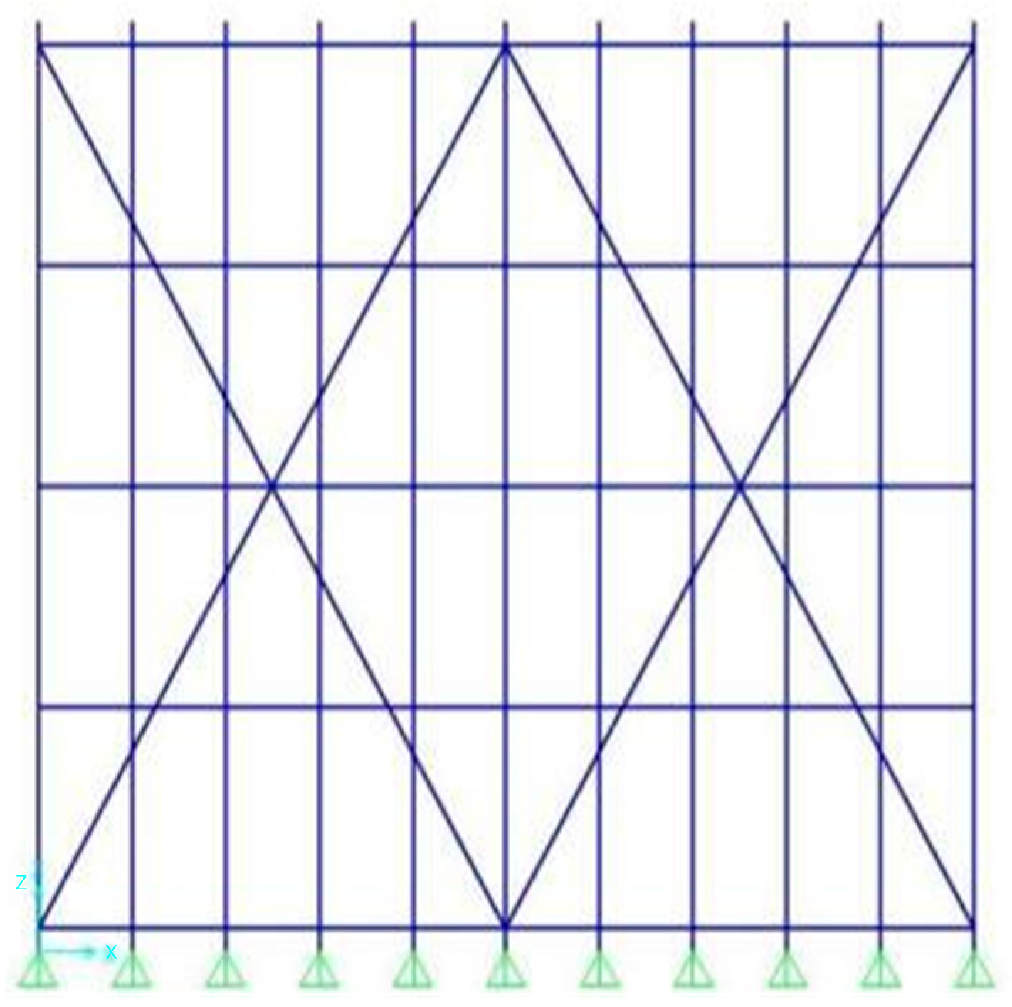
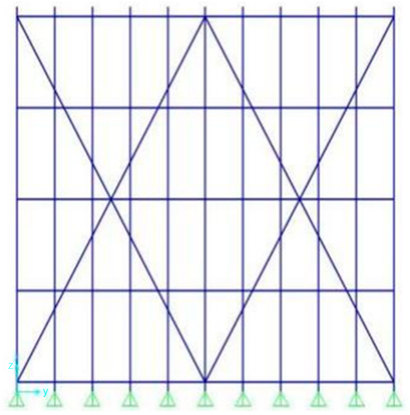
In accordance with the “Safety Technical Specification for Fastening Steel Pipe Scaffolding for Building Construction” (JGJ130-2011) and the requirements of Du Rongjun [32] on the setting of scissor bracing, considering the actual situation at the construction site, a finite element model of fastening steel pipe formwork bracket with different erection parameters is established; the top projection height of the erection model is 0.2 m, the height of the sweeping rod is 0.2 m, the specific erection parameters are shown in Table 10, and the finite element model is shown in Figure 6, Figure 7 and Figure 8.

2.4.4. Analysis of the Stable Bearing Capacity of the Uprights

Fastening-type steel pipe formwork brackets in the actual erection, steel pipe, and fasteners introduce certain initial defects, such as steel pipe initial bending, steel pipe corrosion, fastener wear, and so on. Initial defects on the fastener-type steel pipe formwork bracket stable bearing capacity will have a certain impact. Therefore, in the finite element model of the fastener-type steel pipe formwork bracket established, the influence of initial defects on the stable bearing capacity of the frame is considered by applying a load in the horizontal direction of the frame, the size of which is 1% [33] of the ultimate bearing capacity.
The finite element analysis of the stable bearing capacity of the formwork bracket under different erection parameters in Table 10 was obtained, and the stable bearing capacity of the formwork bracket under different erection parameters, the finite element analysis results of the stable bearing capacity of the uprights, the theoretical calculation results, and the calculation results of the current code are shown in Table 11.

3. Result

In this paper, through the study of the calculation method of the stability bearing capacity of the fastener-type steel pipe formwork support it is found that, based on the theory of the semirigid frame with lateral displacement, the constraint coefficient K of the end of the vertical bar is obtained by modifying the stiffness α u of the end of the horizontal bar. Considering the factors such as node stiffness, step distance, and vertical bar spacing, the stability bearing capacity of the vertical bar calculated by the theory of the semirigid frame with lateral displacement takes into account the influence of the semirigidity of the node and the stability bearing capacity of the adjacent bars. According to the research results, it can be seen that the influence of the step distance and the spacing of the uprights on the stability bearing capacity of the frame is consistent, which is reflected in the theory, specification, and finite element results of the stability bearing capacity of the uprights. That is, as the step distance and the spacing of the uprights decrease, the stability bearing capacity of the uprights increases. Compared with the standard limit, the maximum error is 24.7% and the minimum error is only 1.5%.

4. Discussion

In this paper, the torsional stiffness performance of right-angle fasteners is studied by experimental method, and the calculation method of the stable bearing capacity of formwork support is studied by theoretical research. Using finite element software, the influence of different erection parameters on the stability bearing capacity of formwork support is analyzed, but there are still some shortcomings which need further study.
(1) The theory of semirigid connection frame with lateral displacement is analyzed by the three-story frame structure model when the effective length coefficient of the frame column is deduced, and the influence of the height of the frame on the stability bearing capacity of the bar is not considered.
(2) This paper studies the influence of the torsional moment of the fastener bolt on the stiffness of the joint, and the change of the stability bearing capacity of the vertical bar under the asynchronous distance and the vertical bar. However, there is no specific consideration of the layout of the scissors. This problem needs to be considered in subsequent research.

5. Conclusions

Based on the experimental research, this paper makes a theoretical study on the stability bearing capacity of the fastener-type steel pipe formwork support. Combined with the calculation formula of the stability of the vertical rod given by the current specification JGJ 130-2011, the bearing capacity of the vertical rod under different erection parameters is carried out. After calculation, the following conclusions are drawn:
(1)
Through the experimental study on the torsional stiffness performance of right-angle fasteners, the moment–rotation relationship model of joints and the corresponding initial stiffness of joints under different working conditions are obtained.
(2)
The influence of step distance and vertical bar spacing on the stability bearing capacity of the frame is consistent, which is reflected by the theory, specification, and finite element results of the stability bearing capacity of the vertical bar.
(3)
Based on the theory of semirigid frame with lateral displacement, the stability bearing capacity of the vertical bar is compared with the calculation results according to the current code. It is found that the maximum error is 24.7% and the minimum error is 1.5%. The finite element analysis results of the stability bearing capacity of the vertical bar are the largest, because the finite element analysis model is ideal.

Author Contributions

Conceptualization, M.J. and F.Z.; data curation, F.Z. and Y.D.; formal analysis; financing acquisitions, F.Z.; survey, M.J. and Y.D.; methodology, M.J.; project Management, Y.F.; resources, F.Z.; software, M.J.; supervision, F.Z; verification, Y.F.; visualization, M.J., Y.D. and Y.F.; writing-first draft, Y.F.; authors M.J., Y.D., F.Z. and Y.F. All authors have read and agreed to the published version of the manuscript.

Funding

The work was financially supported by national key R & D plan (2018YFCO808405); 2018 Science and Technology Plan Project of Science and Technology Bureau of Weiyang District of Xi’an City (201844).

Institutional Review Board Statement

Not applicable.

Informed Consent Statement

Not applicable.

Data Availability Statement

Data available on request due to restrictions eg privacy or ethical. The data presented in this study are available on request from the corresponding author.

Acknowledgments

The work was financially supported by national key R & D plan (2018YFCO808405); 2018 Science and Technology Plan Project of Science and Technology Bureau of Weiyang District of Xi’an City (201844).

Conflicts of Interest

The authors declare that they have no conflict of interest.

References

  1. Guo, Z. The development and prospect of formwork scaffold technology. Constr. Technol. 2018, 6, 79–83. [Google Scholar]
  2. Shao, Z. Study on Stability Bearing Capacity and Progressive Collapse Prevention of Inclined Pillar Formwork Support of Cooling Tower. Master’s Thesis, Shandong University, Jinan, China, 2018. Available online: https://kns.cnki.net/KCMS/detail/detail.aspx?dbname=CMFD201802&filename=1018099375.nh (accessed on 12 February 2023).
  3. Hu, C.; Guo, Y.; Mei, Y.; Bao, X. Experimental study on bearing capacity of formwork support system. J. Xi’an Univ. Archit. Technol. 2017, 2, 179–186. [Google Scholar] [CrossRef]
  4. Hu, C.; Che, J.; Zhang, H.; Dong, P. Analysis of the influence of semi-rigid joints on the stability bearing capacity of fastener-style steel tubular formwork supports. Ind. Build. 2010, 2, 20–23. [Google Scholar] [CrossRef]
  5. Zhuang, J.; Cai, X. Study on anti-sliding constitutive relation of steel tubular joints with right-angle fasteners. Constr. Technol. 2011, 5, 79–81. [Google Scholar]
  6. Lu, Z.; Guo, C.; Yang, Y.; Chen, Z. Effect of fastener eccentricity on bearing capacity of steel pipe formwork support. Industrial Building 2016, 1, 140–146. [Google Scholar] [CrossRef]
  7. Lu, Z.; Guo, C.; Li, Y.; Chen, Z.; Zhao, L.; Yu, L. Experimental study on bearing capacity of ultra-high fastener type steel pipe scaffold. Constr. Technol. 2016, 15, 82–85+118. [Google Scholar]
  8. Lu, Z.; Guo, C.; Wen, Y.; Chen, Z.; Liu, T.; Cao, S. Study on the bearing capacity of fastener-style steel tube full support system under eccentric load. J. Dalian Univ. Technol. 2016, 1, 20–27. [Google Scholar]
  9. Li, S.; Wang, J.; Yu, Z.; Li, Y.; Guo, H. Study on the Bearing Capacity of Steel Formwork Concrete Columns. Buildings 2023, 13, 820. [Google Scholar] [CrossRef]
  10. Zhao, L.; Zhang, H.; Mbachu, J. Multi-Sensor Data Fusion for 3D Reconstruction of Complex Structures: A Case Study on a Real High Formwork Project. Remote Sens. 2023, 15, 1264. [Google Scholar] [CrossRef]
  11. Makarova, A.A.; Kaliberda, I.V.; Kovalev, D.A.; Pershin, I.M. Modeling a Production Well Flow Control System Using the Example of the Verkhneberezovskaya Area. In Proceedings of the 2022 Conference of Russian Young Researchers in Electrical and Electronic Engineering (ElConRus), Saint Petersburg, Russia, 25–28 January 2022; pp. 760–764. [Google Scholar] [CrossRef]
  12. Makarova, A.A.; Mantorova, I.V.; Kovalev, D.A.; Kutovoy, I.N. The Modeling of Mineral Water Fields Data Structure. In Proceedings of the 2021 IEEE Conference of Russian Young Researchers in Electrical and Electronic Engineering (ElConRus), St. Petersburg and Moscow, Russia, 26–29 January 2021; pp. 517–521. [Google Scholar] [CrossRef]
  13. Martirosyan, A.V.; Ilyushin, Y.V. Modeling of the Natural Objects’ Temperature Field Distribution Using a Supercomputer. Informatics 2022, 9, 62. [Google Scholar] [CrossRef]
  14. Jia, L. Study on Mechanical Properties and Design Method of Steel Tubular Scaffold with Fasteners. Ph.D. Thesis, Tianjin University, Tianjin, China, 2017. Available online: https://kns.cnki.net/KCMS/detail/detail.aspx?dbname=CDFDLAST2020&filename=1019894533.nh (accessed on 2 January 2023).
  15. Jia, L.; Liu, H.; Chen, Z.; Liu, Q.; Wen, S. Checking method for bearing capacity of fastener-style steel tubular scaffold. Build. Struct. 2016, 6, 71–76. [Google Scholar] [CrossRef]
  16. Cheng, H. Destructive experimental study on neutral rod of fastener-type steel pipe formwork support system. Master’s Thesis, Shenyang Jianzhu University, Shenyang, China, 2014. Available online: https://kns.cnki.net/KCMS/detail/detail.aspx?dbname=CMFD201701&filename=1015360493.nh (accessed on 6 April 2023).
  17. Xie, X.; Chen, G.; Yin, L. Multi-parameter simulation method for semi-rigid joints of steel tubular fastener scaffold. Chin. J. Civ. Environ. Eng. 2019, 4, 92–103. [Google Scholar]
  18. Lin, H.; Huang, C.; Liu, C.; Li, Y.; Liu, J.; Lu, L.; Xie, M. Scaffolding experimental study and finite element analysis considering right-angle fastener failure. Build. Struct. 2019, S2, 689–695. [Google Scholar] [CrossRef]
  19. Saritas, A.; Koseoglu, A. Distributed inelasticity planar frame element with localized semi-rigid connections for nonlinear analysis of steel structures. Int. J. Mech. Sci. 2015, 96–97, 216–231. [Google Scholar] [CrossRef]
  20. Zhang, H.; Rasmussen, K.J.R. System-based design for steel scaffold structures using advanced analysis. J. Constr. Steel Res. 2013, 89, 1–8. [Google Scholar] [CrossRef]
  21. Pieńko, M.; Błazik-Borowa, E. Numerical analysis of load-bearing capacity of modular scaffolding nodes. Eng. Struct. 2013, 48, 1–9. [Google Scholar] [CrossRef]
  22. Beale, R.G. Scaffold research—A review. J. Constr. Steel Res. 2014, 98, 188–200. [Google Scholar] [CrossRef] [Green Version]
  23. The Ministry of Housing and Urban-Rural Development notified the production safety accidents of housing and municipal engineering in 2019. Stand. Eng. Constr. 2020, 7, 51–53. (In Chinese)
  24. Liu, S. Experimental Study on the Mechanical Mechanism of Full-Hall Fastener-Type Steel Pipe Scaffold Based on BOTDA Technology. Master’s Thesis, Anhui Jianzhu University, Hefei, China, 2015. Available online: https://kns.cnki.net/KCMS/detail/detail.aspx?dbname=CMFD201601&filename=1015420368.nh (accessed on 3 January 2023).
  25. JGJ 130-2011; Industry Standard of the People’s Republic of China. Technical Code for Safety of Steel Tube Scaffold with Fasteners in Construction. China Building and Building Press: Beijing, China, 2011.
  26. GB 15831-2006; National Standard of the People’s Republic of China General Administration of Quality Supervision, Inspection and Quarantine. China National Standardization Management Committee: Beijing, China, 2006.
  27. Chen, Z.; Lu, Z.; Wang, X. Numerical simulation analysis and experimental study on the stiffness of right angle fasteners of steel pipe scaffold. J. Civ. Eng. 2010, 9, 100–108. [Google Scholar] [CrossRef]
  28. Wang, J.; Li, G. Effective length coefficient of composite frame column with lateral displacement semi-rigid connection. Eng. Mech. 2007, 3, 71–77+90. [Google Scholar]
  29. GB 50017-2003; Standard Steel Structure Design Code of the People’s Republic of China. General Administration of Quality Supervision: Beijing, China, 2003.
  30. Chen, Z.; Lu, Z.; Wang, X.; Liu, H.; Liu, Q. Stability bearing capacity analysis and experimental study of unsupported formwork supports based on the theory of semi-rigid connection frame with lateral displacement. J. Build. Struct. 2010, 12, 56–63. [Google Scholar] [CrossRef]
  31. Gong, Z. Theoretical Analysis of Progressive Collapse Resistance of Fastener-Style Steel Tubular Formwork Supports. Master’s Thesis, Chongqing University, Chongqing, China, 2013. Available online: https://kns.cnki.net/KCMS/detail/detail.aspx?dbname=CMFD201401&filename=1013045050.nh (accessed on 3 January 2023).
  32. Du, R. Design calculation and construction management points of scaffold and support engineering safety 3. Constr. Technol. 2016, 21, 139–143. (In Chinese) [Google Scholar]
  33. He, X.; Qi, H.; Shao, C. Analysis of the influence of non-synchronous distance on the bearing capacity of fastener-style steel tubular scaffold. J. Anhui Jianzhu Univ. 2015, 4, 11–16. [Google Scholar]
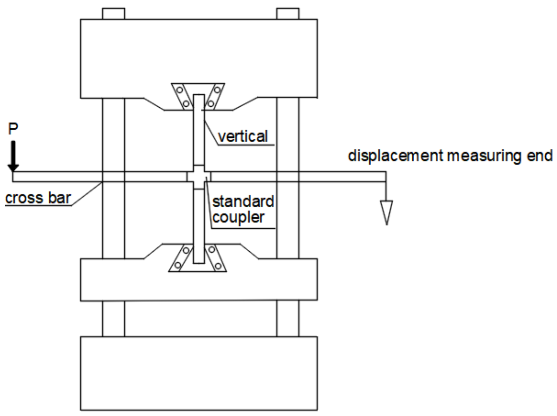
Figure 1. Test setup diagram.
Applsci 13 04838 g001
Figure 2. Deformation of bar under load.
Applsci 13 04838 g002
Figure 3. Bending moment–rotation angle curve of nodes under different torsional moments.
Applsci 13 04838 g003
Figure 5. Semirigid restraint bars at both ends.
Applsci 13 04838 g005
Figure 6. Finite element model of fastener steel tube formwork bracket: XZ plane.
Applsci 13 04838 g006
Figure 7. Finite element model of fastener steel tube formwork bracket: YZ plane.
Applsci 13 04838 g007
Figure 8. Template support space model.
Applsci 13 04838 g008
Table 1. Initial stiffness values of nodes under different working conditions.
Instrument NameParameter
Microcomputer controlled electrohydraulic servo Universal testing machineregulating range: 800 mm–1300 mm
Torque wrenchmoment range: 0–100 N· m
Digital vernier caliperPrecision: 0.01 mm
Standard weights5 kg per mass
Table 2. Test instrument parameters.
Test NumberBolt Torsion Moment (N·m)Rotating Angle Formula
KJ1-120 θ = tan 1 f 1000
KJ1-230
KJ1-340
KJ1-450
KJ1-560
Table 3. Quadratic function fitting right angle fastener connection moment–rotation function formula.
Test NumberMoment of Twisting (N·m)Fitting FormulaThe Initial Stiffness Value of the Joint (kN·m/Rad)
KJ1-120 M = 28.44 θ 2 + 10.14 θ + 0.1010.14
KJ1-230 M = 72.09 θ 2 + 16.61 θ + 0.0616.61
KJ1-340 M = 164.08 θ 2 + 24.35 θ + 0.0924.35
KJ1-450 M = 264.90 θ 2 + 31.67 θ + 0.0631.67
KJ1-560 M = 226.11 θ 2 + 42.37 θ + 0.0242.37
Table 4. Stable bearing capacity of vertical rod under fastener rotational stiffness.
Moment of Twisting (N·m)Joint Initial Rigidity (kN·m/rad)Extension (m)Lag Spacing (m)Coefficient for Effective Length μ Buckling Strength (kN)
2010.871.51.2 × 1.23.0112.70
3019.251.51.2 × 1.22.4219.68
4026.031.51.2 × 1.22.1824.18
5033.181.51.2 × 1.22.0228.12
6042.401.51.2 × 1.21.8932.31
Table 5. Effective length coefficient μ of vertical bar based on theory of semirigid frame with lateral displacement.
PacePole Pitch (m)
1.2 × 1.21.0 × 1.00.9 × 0.9
1.52.962.952.94
1.23.273.253.24
Table 6. Based on the theory of semirigid frame with lateral displacement, the stable bearing capacity of vertical bar is analyzed(kN).
PacePole Pitch (m)
1.2 × 1.21.0 × 1.00.9 × 0.9
1.513.0813.2313.31
1.216.7716.9717.07
Table 7. Limits of the standard bearing capacity of vertical pole stability.
Work ConditionsPace (m)Pole Pitch (m)Height (m)Stable Bearing Capacity (m)
11.51.2 × 1.2<814.52
21.51.0 × 1.0<815.97
31.50.9 × 0.9<816.60
41.21.2 × 1.2<815.97
51.21.0 × 1.0<817.22
61.20.9 × 0.9<818.67
Table 8. Steel pipe material parameters.
Elastic Modulus (E, N/mm2)Poisson’s Ratio (μ)Yield Strength (f, N/mm2)
2.06 × 1050.3205
Table 9. Geometric characteristics steel tube section.
Outer Diameter d (mm)Wall Thickness t (mm)Cross-Sectional Area A (cm2)Moment of Inertia I (cm4)Turning Radius i (cm)
48.33.65.0612.711.59
Table 10. Parameters of template support erection.
Work ConditionsPace (m)Pole Pitch (m)Number of Vertical and Horizontal SpansHeight (m)
11.51.2 × 1.2107.9
21.51.0 × 1.0107.9
31.50.9 × 0.9107.9
41.21.2 × 1.2107.6
51.21.0 × 1.0107.6
61.20.9 × 0.9107.6
Table 11. Theory, specification, and finite element results of vertical rod stability bearing capacity.
Work ConditionsPace (m)Pole Pitch (m)Stable Bearing Capacity Theoretical (kN)Stable Bearing Capacity Code Limit Value (kN)Stable Load Carrying Capacity Finite Element Results (kN)
11.51.2 × 1.213.0814.5217.92
21.51.0 × 1.013.2315.9718.93
31.50.9 × 0.913.3116.6019.48
41.21.2 × 1.216.7715.9720.51
51.21.0 × 1.016.9717.2221.86
61.20.9 × 0.917.0718.6722.58
Disclaimer/Publisher’s Note: The statements, opinions and data contained in all publications are solely those of the individual author(s) and contributor(s) and not of MDPI and/or the editor(s). MDPI and/or the editor(s) disclaim responsibility for any injury to people or property resulting from any ideas, methods, instructions or products referred to in the content.