Article

A Numerical Study of Blast Resistance of Carbon Fiber Reinforced Aluminum Alloy Laminates

State Key Laboratory of Explosion Science and Technology, Beijing Institute of Technology, Beijing 100081, China
*
Author to whom correspondence should be addressed.
Appl. Sci. 2023, 13(8), 4906; https://doi.org/10.3390/app13084906
Submission received: 6 March 2023 / Revised: 1 April 2023 / Accepted: 4 April 2023 / Published: 13 April 2023
(This article belongs to the Section Materials Science and Engineering)

Abstract

:
In this study, the dynamic responses under blast loading of carbon fiber reinforced aluminum alloy laminates with different curvature radii, different numbers of layers, and different layer directions of carbon fiber under blast loading were compared numerically. The finite element models were built with ABAQUS/Explicit. To calibrate the numerical models, experiments on curved carbon fiber and curved aluminum alloy were modeled, and the numerical results showed good agreement with the experimental data. The calibrated numerical models were used to simulate the dynamic response of cylindrical panels subject to external explosion loading. The stiffness degradation coefficient was introduced to more accurately simulate the failure mode of the composite structures. The deformation and energy absorption of carbon fiber reinforced aluminum alloy laminates under different structural parameters were obtained. These simulation findings can guide the theoretical study and optimal design of carbon fiber reinforced structures subject to external blast loading.

1. Introduction

The fusion of metal alloy and fiber reinforced composite material overcomes the limitation of metal and composite material alone, and is widely used in aviation and national defense fields as a protective structure. FML (fiber metal laminate) structures combine the high specific strength of fiber and the impact resistance of metal, so that the composite structure has the advantages of low crack growth rate, high toughness, low density, etc., and its impact resistance has become a popular research topic [1,2,3,4,5,6,7,8,9,10,11,12,13,14,15,16,17,18,19,20]. This paper focuses on the study of CARALL (carbon fiber reinforced aluminum alloy laminate).
In practice, Xu [21] used high-speed ballistic impact test to analyze the anti-penetration performance of CARALL with flat, pointed, and round head projectiles, and used the method of defining a user subroutine in ABAQUS finite element software to more accurately describe the three-dimensional progressive damage model of carbon fiber. The results show that CARALL has excellent elastic resistance, especially for flat-headed projectiles. Yao et al. [22] investigated the low-velocity impact behavior of FMLs consisting of carbon fiber reinforced layers and aluminum sheets under multiple impacts with the same total energy. The results revealed that multiple impacts with lower energy division and smaller initial impact energy can cause minor damage in FMLs. Lin X. H [23] conducted high-speed impact simulation analysis of three types of CARALL, and compared the impact resistance performance of these CARALL laminates under different impact factors. In this paper, the deformation and energy absorption of specimens and the matrix damage, fiber damage, and bond delamination of materials are also compared and analyzed. The study shows that, for the same thickness, the alternating stratification of the CARALL layer is more important in controlling the deformation and the impact ability of each layer’s injury. Lee et al. [24] analyzed CARALL and GLARE laminates with different fiber arrangements and metal layer arrangements using the drop hammer method, and found that the generation and expansion of cracks are mainly affected by the fiber arrangement direction. Hu et al. [25] proved through bending tests that FMLs can endure higher bending strength along the fiber direction compared to FMLs with cross-ply layups.
The above studies indicate that the number of fiber and metal layers, the direction of the fiber arrangement, and the order of the fiber and metal arrangement in FMLs play a crucial role in the impact resistance of FMLs. However, all of the above studies are based on planar FMLs structures or the mechanical properties of FML structures under quasi-static conditions [13,26]. In the research background of this paper, the protective structure is a curved structure. Due to the structural characteristics, there are many differences between the deformation failure modes of FMLs under quasi-static conditions for curved structures and planar structures. There are only a few studies of such structures in the existing literature.
Puneet et al. [14] used a shock tube device to simulate the effect of explosion shock on fiber composite structures with different radii of curvature. The results show that the change in curvature will greatly affect the reflection and slip of the blast shock load on the panel, and the failure mode of fiber will also change. Bai, Y. [15] simulated the response characteristics of CARALL under explosive load by establishing a double-layer CARALL curved composite plate and adopting CONWEP loading mode in ABAQUS. The results show that, with the decrease in the curvature radius, CARALL’s absorption of explosion energy decreases, the fracture, delamination, and buckling fold of fiber decrease, and the sag deformation and displacement of the aluminum alloy part decrease. It is believed that the reduction in the curvature radius is beneficial to improving the explosive impact resistance of CARALL.
Agha Mohammadi et al. [27] studied the effect of four different surface treatments on the flexural properties of FML materials and analyzed them using scanning electron microscopy (SEM), optical microscopy (OM), and profilometry. Results showed that the mechanical abrasion and alkaline etching treatments were not found to be suitable for enhancing the flexural properties due to weak interfacial adhesive bonding. Forest Products Laboratory etching (FPL-etching) and anodizing treatments form micro-scale pores on the surface oxidation layer, which provides an appropriate position for polymer resin penetration. Through the mechanical interlocking mechanism, the strong interface bond is formed and the bending resistance is significantly improved.
Hossein Rahmani [28] investigated the effect of the type and content of SiO2 and ZrO2 nanoparticles in the epoxy matrix on the high-speed impact performance of carbon fiber reinforced aluminum laminate (CARALL). Typical field emission scanning electron microscopy (FESEM) was used to observe the toughening effect of nanoparticles on the surface of CARALL fractures after impact. The results show that the controlled addition of SiO2/ZrO2 rigid nanoparticles in CARALL is a promising method to improve the energy absorption of CARALL during a high-speed impact.
It can be seen from the impact response analysis of FMLs mentioned above that, in order to explore the explosive impact resistance of curved FMLs, it is necessary to carry out research on the metal fiber metal arrangement, fiber direction, and curvature radius of the composite structure of a multi-layer fiber metal curved surface. In this paper, many design parameters, failure models, energy absorption characteristics, and optimization methods are analyzed by studying the explosive impact resistance performance of curved FMLs.
In this study, four kinds of CARALL with different curvature radii (30–120 mm) with a ladder distribution were designed. Each gradient adopts three kinds of laminating methods (2, 4, 8) and five kinds of fiber arrangement methods (D0-DX). The clamping boundary is adopted, and the finite element analysis software ABAQUS/Explicit was used to carry out analysis of the external explosion load on each sample.

2. Problem Description

2.1. Geometry Description

The FML structure studied in this paper is shown in Figure 1. The main body of the structure is made of carbon fiber and aluminum alloy, the radius of curvature is 30–120 mm, the total thickness is 2.4 mm, and the axial length is 50 mm. One-quarter of the model is used for loading due to the double symmetry of the structure. The boundary conditions of the model are fixed. The model is subjected to 25 g TNT equivalent explosive shock wave loading 100 mm from the center.

2.2. FML Structure Design

The protective structure used in this study is bonded by aluminum alloy and multi-layer carbon fiber, and the specific form is shown in Figure 1. The material distribution and delamination parameters in different FML structures are shown in Table 1. The interface between the fiber and fiber and aluminum alloy is connected by adhesive. Different FML structures are adjusted by R, t, α, and β, where R is the radius of curvature of the composite structure, t is the width of the clamping boundary, α is the angle from the center of the specimen to the lower boundary of the clamping boundary, and β is the angle from the center of the specimen to the lower boundary of the clamping boundary. When studying the influence of structural curvature, the structural parameters satisfy the following relations (B = 30, R = 90 mm, fixed constant 1 = 27, fixed constant 2 = 0.1) in order to ensure that the action area of load and the proportion of clamping remain unchanged:
β R = c o n s t a n   t 1
t W = β α β = c o n s t a n   t 2
As shown in Figure 2, the fiber layer is defined as 0° along the circumferential direction and 90° along the axial direction, and the remainder of the angles are rotated around the normal vector n of the surface.

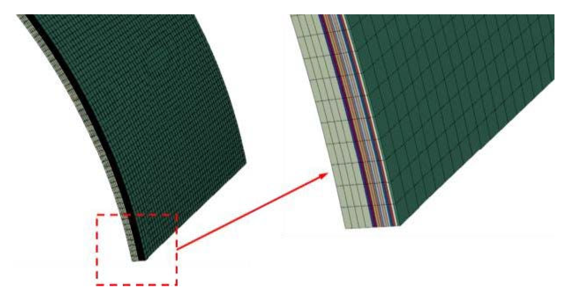
3. Finite Element Modeling

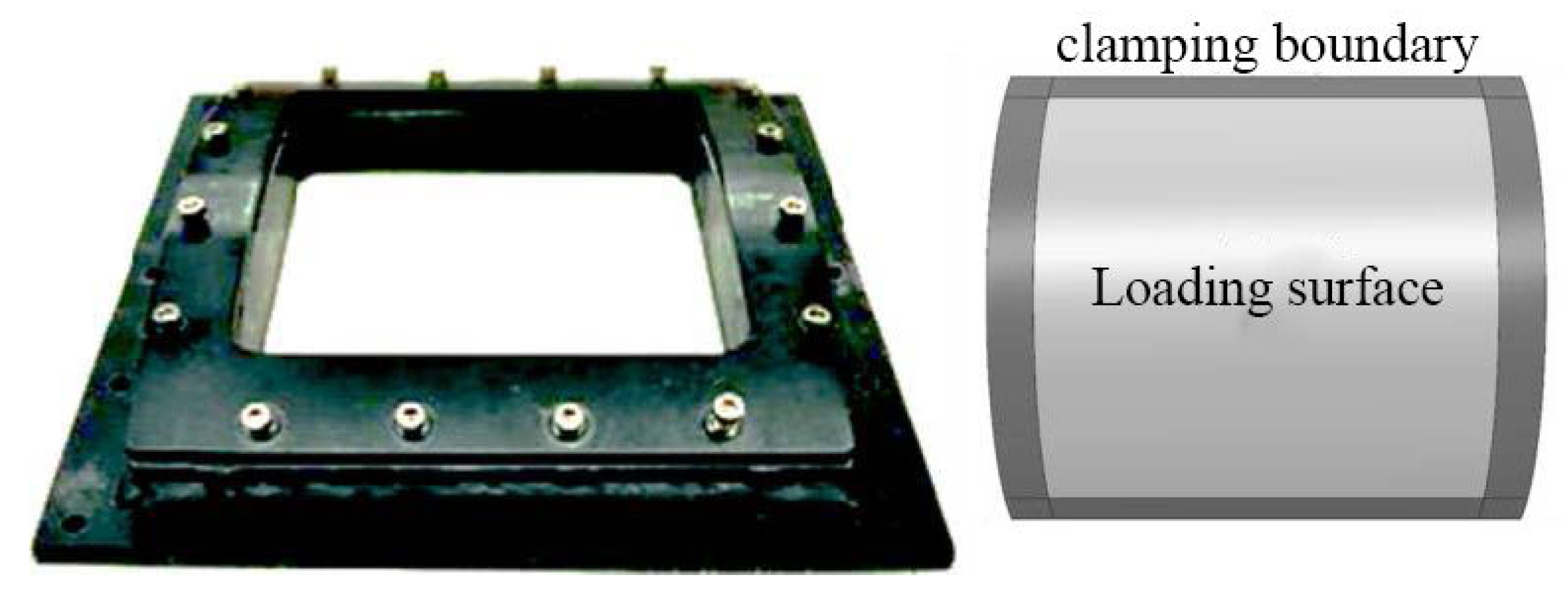
3.1. Geometry, Boundary Conditions, and Contact Modeling

All numerical simulations were carried out with the FE code ABAQUS/Explicit. Only a quarter of the panel was modeled to shorten the simulation time due to the double-symmetry nature of the problem. Corresponding constraints were defined on the two symmetric planes, while the other edges were fully clamped, as shown in Figure 3. Li et al. [16] compared the difference between the screw fixation constraint and boundary fixation constraint, and the results showed that the constraint mode only had an effect on the vibration characteristics of the structure, but had no effect on the maximum deformation. In this paper, the boundary node fixation constraint was used to replace the screw constraint.
Aluminum alloy and carbon fiber were meshed using ABAQUS shell element C3D8R. The element size was set to be 1 mm, as shown in Figure 4. The normal contact of shell elements was defined using hard contact formulation, while the tangential behavior was described with a penalty with a friction coefficient of 0.3.
The delamination failure of the fiber–metal composite layer includes impact delamination between layers, peeling off of the fiber layer, and delamination between the fiber layer and aluminum alloy. Two ways of simulating delamination are provided in ABAQUS/Explicit: Cohesion finite elements and Cohesion Contact. As the thickness of the bonding layer between fiber layers was very small, its influence could be ignored [22]. In this paper, failure of Cohesion Contact with a thickness of 0 was selected to simulate the impact of delamination between fiber layers.
The viscous behavior contact provided in the Interaction module of ABAQUS uses linear elastic adherence–separation behavior, as shown in Figure 5. In the three-dimensional stress state, the interlayer contact stress t is defined as:
t = t n t s t t = K n n K n s K n t K n s K s s K s t K n t K s t K t t δ n δ s δ t = K δ
where tn is normal stress in direction 3 as shown in Figure 6, ts is shear stress in direction 1, and tt is shear stress in direction 2. The corresponding separation displacements are δ n , δ n , and δ k , and K is bond stiffness. When the normal stress or shear stress between layers reaches the corresponding strength limit (point A), the bonding contact begins to fail. The general maximum stress separation criterion can be written as follows:
Figure 5. Linear elastic adhesion–separation viscous behavior of progressive damage failure.
Applsci 13 04906 g005
Figure 6. One-way fiberboard coordinate system.
Applsci 13 04906 g006
max t n t n o , t s t s o , t t t t o = 1
where t n o , t s o , t t o are the strength limits in the corresponding direction, and the < > symbol means absolute value. In the three-dimensional complex stress state, delamination occurs before the normal stress reaches the strength value due to the contribution of shear force. In this paper, the secondary stress separation criterion is adopted:
t n t n o 2 + t s t s o 2 + t t t t o 2 = 1
According to the relevant literature [15,21], in the 3D simulation model, linear stiffness degradation controlled by displacement is adopted. Linear elastic adherence–separation viscosity behavior of the secondary stress separation criterion is shown in Figure 7 and contact parameters are shown in Table 2.

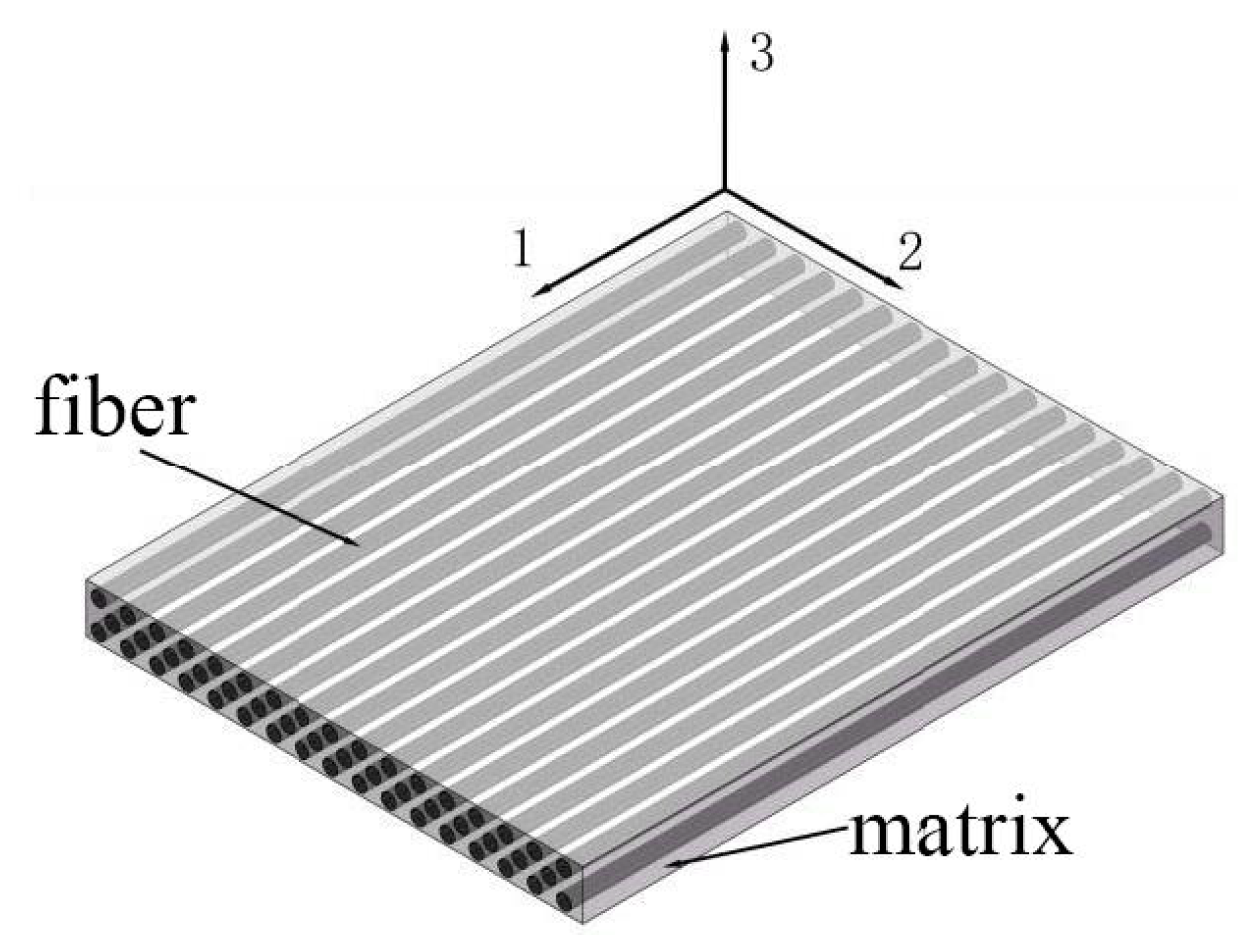
3.2. Material Properties and Modeling

In this paper, the FML structure is composed of an aluminum alloy plate and carbon fiber superposition. The thickness of the aluminum 2024-T3 panel in different FML structures is 0.3, 0.6, and 1.2 mm. The aluminum alloy material parameters are shown in Table 3. The carbon fiber is T700s (Hercules Corporation, Magna, UT, USA), and the layering direction is [0°–90°]. The material parameters of carbon fiber are shown in Table 4.

3.3. Damage Model of Composite Material

In engineering application, the impact of CARALL is a transient three-dimensional stress problem, so it is necessary to establish a three-dimensional model to analyze it. When the 3D damage model is adopted, the initial damage is usually taken as the judgment basis, that is, when the element in the calculation meets the initial damage condition, the element is judged as the failing element and deleted. According to the interpretation of the judgement method in the ABAQUS user manual, although this treatment can improve the calculation speed, the failure process of the fiber material during the damage is ignored. The test results show that, when the fiber composite material is damaged, it still has a certain bearing capacity, and adopting the material stiffness degradation technology can more accurately reflect the objective damage process of the material.
In this paper, the impact failure criterion of unidirectional fiber adopts the three-dimensional Hashin failure criterion improved by Xu and Shokrieh et al. [17], taking into account the shear failure when the center sag of the curved surface structure is deformed, and the impact damage criterion includes five failure modes (the unidirectional fiber coordinate system is shown in Figure 6): fiber tension and compression failure (direction 1), matrix tension and compression failure (directions 2 and 3), matrix shear failure (directions 1–2), out-of-plane shear failure (directions 1–3 and 2–3), and lamination failure.
Tensile failure of fiber in direction 1: It was found through the test that the tensile failure in the fiber layout direction is mainly a tensile fracture:
f 1 2 = ( σ 11 X T ) 2 + α [ ( τ 12 S 12 ) 2 + ( τ 31 S 31 ) 2 ] ( σ 11 > 0 )
where 1, 2, and 3 represent the distribution direction (1), in-plane vertical fiber direction (2), and out-of-plane vertical fiber direction (3) of the carbon fiber; XT, S12, and S31 are the tensile strength in direction 1, the shear strength in plane 1–2, and the shear strength in plane 1–3, respectively; f 1 2 is the damage parameter.
Fiber compression failure in direction 1: Compression failure in the fiber layout direction is mainly the compression fracture of the carbon fiber:
f 2 2 = ( σ 11 X C ) 2 ( σ 11 < 0 )
The matrix tensile failure in directions 2 and 3 is in-plane and out-of-plane in the vertical fiber direction, and the tensile failure of fiber in the one-way plate is mainly a matrix tensile failure, that is, the material failure is judged when the tensile stress in directions 2 and 3 reaches the tensile strength of the matrix. Therefore, the matrix tensile failure criterion of the Hashin criterion can be used in accordance with the tensile failure criterion assumed in directions 2 and 3:
f 3 2 = σ 22 + σ 33 Y T 2 + τ 12 2 + τ 13 2 S 12 2 + τ 23 2 σ 22 σ 33 S 23 2 ( σ 22 + σ 33 > 0 )
After the matrix fails in the in-plane and out-of-plane vertical fiber directions, the fiber and the fractured matrix are subjected to continuous compression loads until the unidirectional carbon fiber cracks and fails:
f 4 2 = ( σ 22 + σ 33 Y C ) 2 ( σ 22 + σ 33 < 0 )
where YC is the compression strength in direction 2, YC = ZC, and f4 is the damage parameter.
Shear failure in the 2–3 plane: Shear failure in the unidirectional fiber plate is the shear stress failure common to the matrix and carbon fiber:
f 5 2 = ( τ 12 S 12 ) 2
In engineering tests, it is found that bending deformation of the curved plate will result in out-of-plane shear load on the fiberboard. However, the failure behavior of fiber composite under out-of-plane shear is not taken into account in most of the existing failure criteria. Therefore, out-of-plane shear failure forms are added in this paper:
f 6 2 = ( τ 13 + τ 23 S 13 ) 2
Composite structures usually do not suddenly lose their ability to bear loads after local damage occurs during loading. Materials with gradually degraded properties are usually used to replace the original materials to simulate the gradual failure process. The model that defines the degradation of the properties of materials after failure is called the Material Property Degradation Model. The choice of degradation model in progressive failure analysis is closely related to the failure criterion adopted. The stiffness degradation model is shown in Figure 8. Multiple failure modes are allowed to occur at the same point, and each failure mode corresponds to a certain degradation. For example, fiber failure occurs in the area of matrix failure. The sudden degradation model is simple and easy to implement because of its duality, that is, the material properties of a point are either intact or completely degraded.
Considering the limitation of elastic constants of orthotropic materials and the requirements of numerical calculation, the degradation coefficients of carbon fibers are shown in Table 5.

3.4. Blast Load Modeling

In this study, blast loading was generated by the COMWEP (conventional weapons effects program) empirical model. The CONWEP algorithms were developed by Kingery and Bulmash [20], and account for the angle of incidence by combining the reflected pressure (normal incidence) value and the incident pressure (side-on incidence) value. The pressure can be calculated by the following equation:
P t = P i n c i d e n t t 1 + c o s θ 2 c o s 2 θ + P r e f l e c t t c o s 2 θ   f o r   c o s θ 0
P t = P i n c i d e n t t   f o r   c o s θ < 0
where θ is the angle of incidence; P i n c i d e n t is the incident pressure; P r e f l e c t is the reflected pressure. The CONWEP model available in ABAQUS/Explicit has two parameters: the equivalent mass of TNT and the standoff distance.

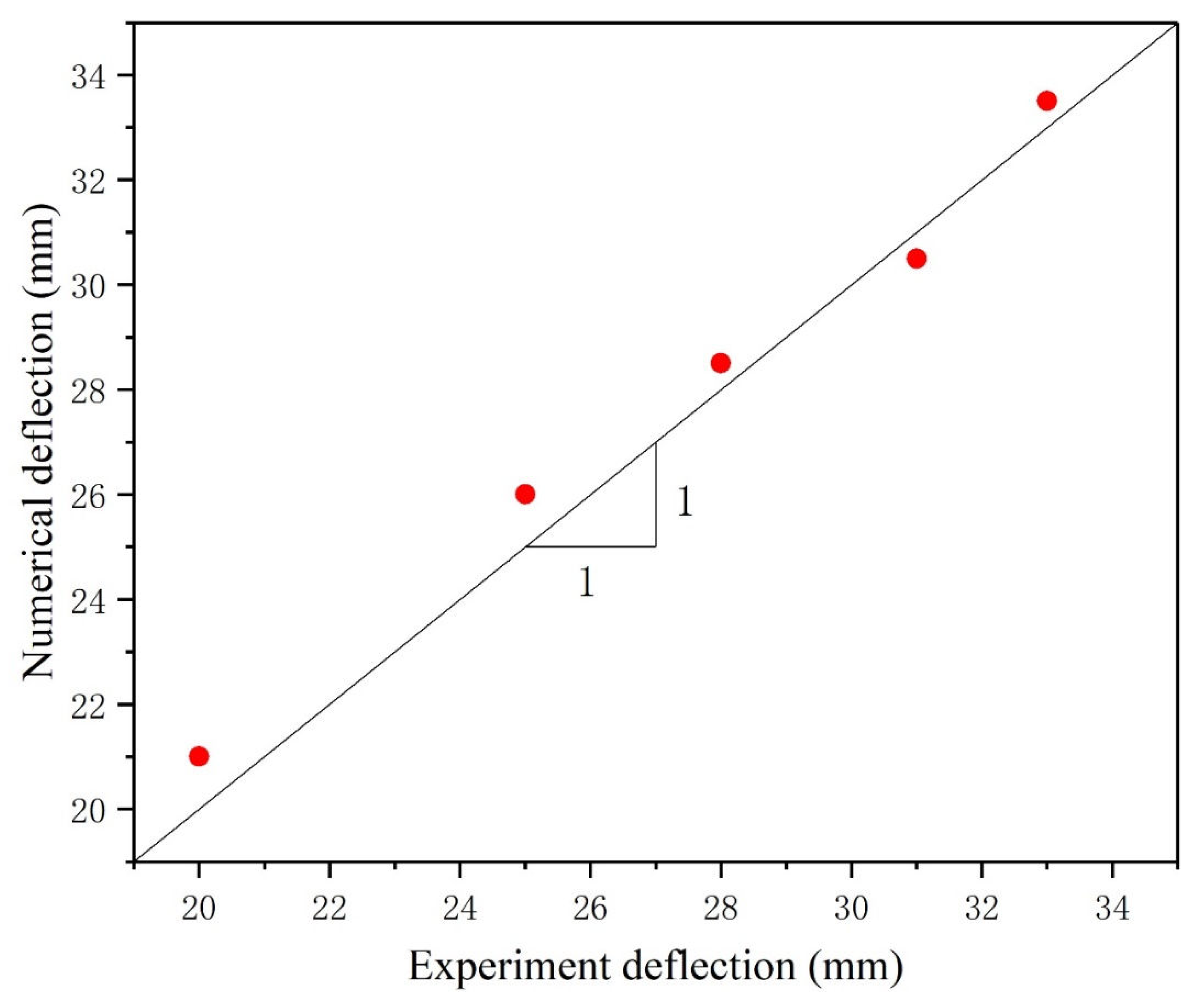
3.5. Validation of FE Model

3.5.1. Validation of Carbon Composite Panels

There is no experimental study of this kind of situation in the existing literature, and the accuracy of the simulation model has been verified by a shock tube impacting a 32-layer carbon fiber composite material [14]. In this study, specimens with a radius of curvature of 305 mm were selected and simulated in ABAQUS/Explicit using the same boundary conditions, material properties, and blast loads.
The comparison results are shown in the Figure 9. Three different failure modes of carbon fiber are compared: matrix failure, fiber delamination, and fiber fracture failure. The results show that the failure modes predicted by numerical simulation are basically consistent with the experimental results.

3.5.2. Validation of Aluminum Panels

The impact dynamic response of aluminum alloy laminates was tested by Puneet et al. [19], and the experimental results were compared with the simulation results. In this paper, the exposed area of aluminum alloy panel is 203.2 × 203.2 mm. Three specimens are flat plate and cylindrical laminate with curvature radii of 304.8 and 111.8 mm, respectively. Shock wave loading is carried out on the specimens through the shock tube. The clamping mode and boundary conditions are the same as those in Section 3.1. The simulation results and test results are compared as shown in Figure 10.
Figure 11 shows the simulation results compared with the center deformation of the test backplane. The simulation results and experimental photos have the same failure form. The deformation trend of the center point of the backplane is the same as the final deformation degree, which verifies the accuracy of the simulation model and also verifies the accuracy of the concept module used for explosive loading, which can be used for subsequent simulation research.

4. Results and Discussion

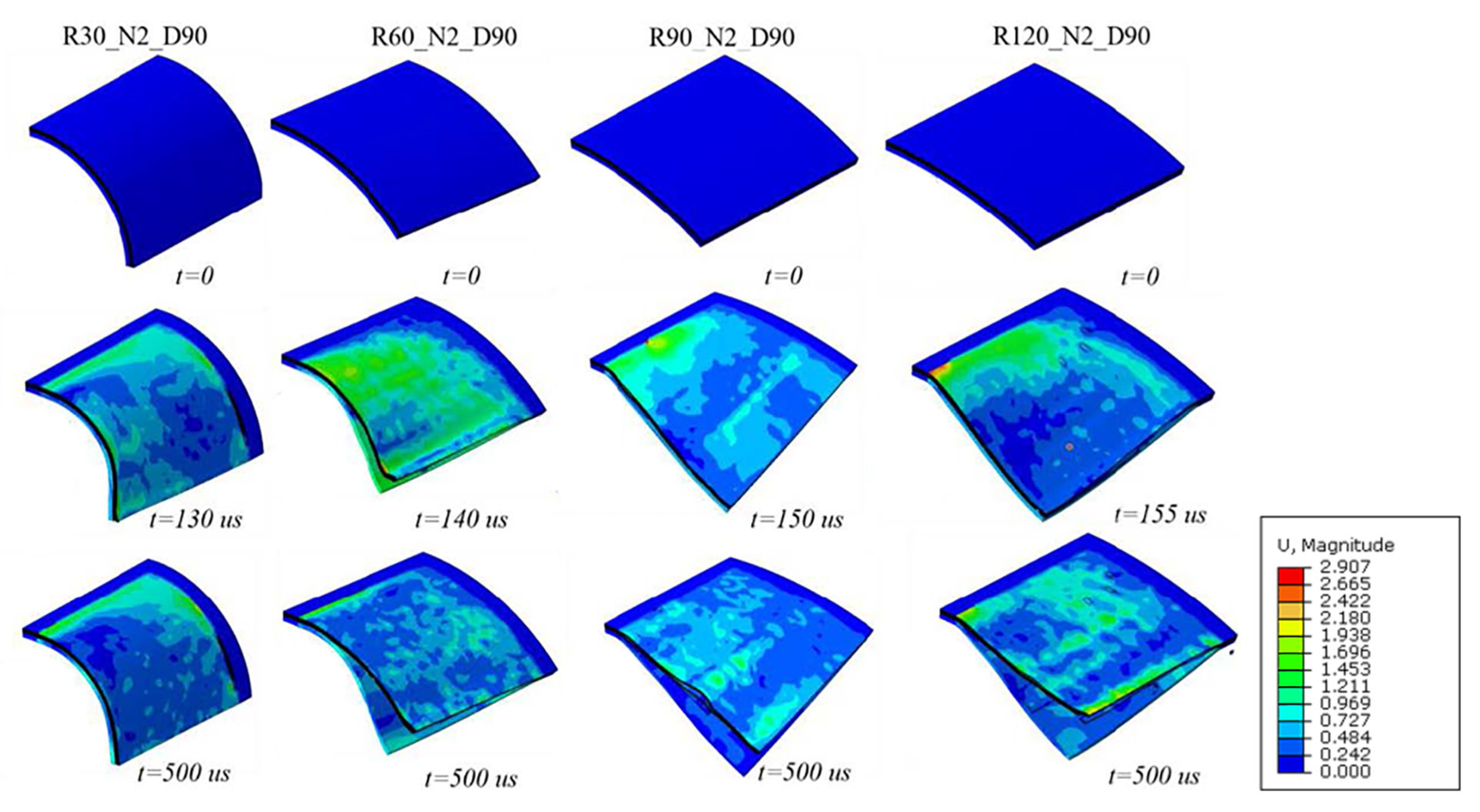
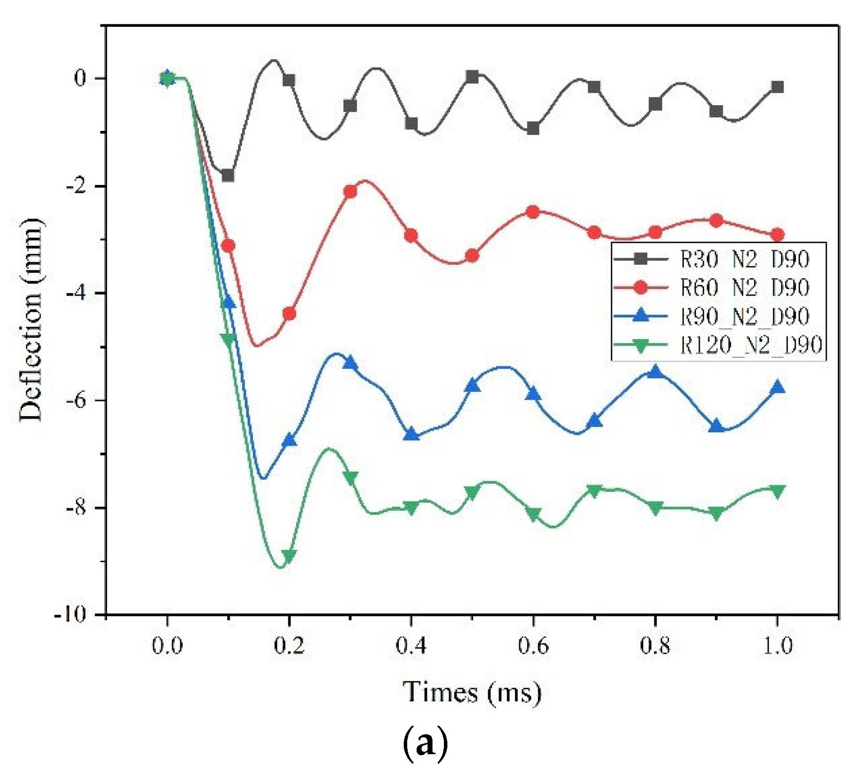
4.1. Influence of Curvature on CARALL Impact Response

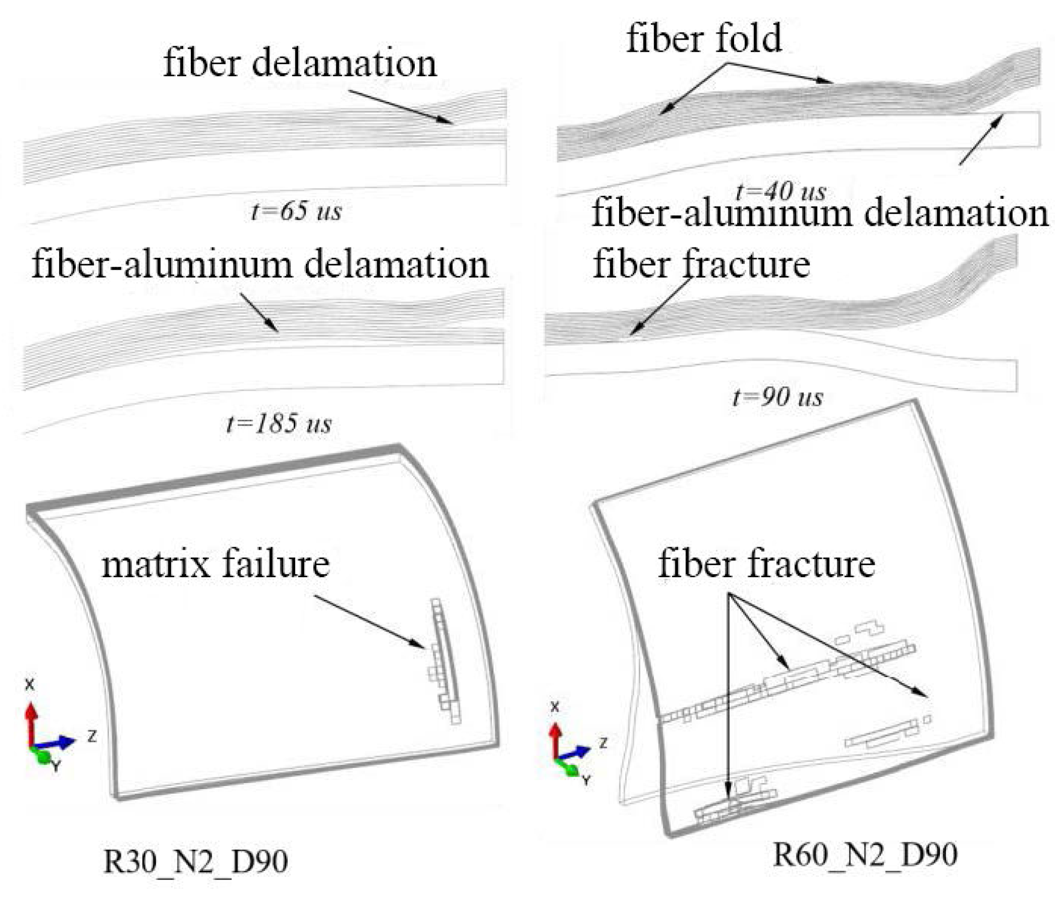
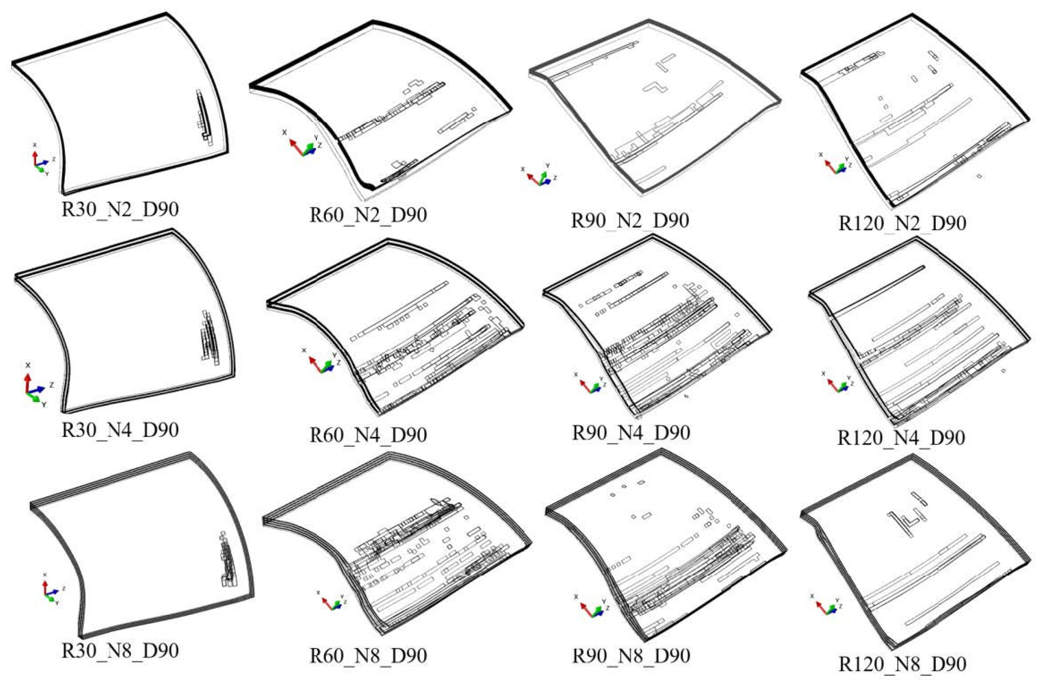
4.1.1. Influence of Curvature on Failure Modes of CARALL Deformation

As the most important structural parameter of the surface structure, the curvature has the most direct effect on structural deformation. Figure 12 compares the deformation history of double-layer CARALL (layering along the circumferential direction) with different curvature radii, and Figure 13 shows its corresponding deformation history at the center point and deformation cloud diagram at the maximum deformation time.
As shown in Figure 13, structural deformation can be divided into three stages: (a) rapid deformation and bending under the action of explosion load to reach the maximum deformation; (b) spring back with the weakening of the explosion load; and (c) the structure undergoes a long period of vibration until energy dissipates.
As shown in Figure 12, when the radius of curvature is small, R30_N2_D90 has a small deformation area and deformation value, and the overall deformation mode of the R30_N2_D90 structure is the central sag deformation. In the fiber part, the failure of lamination between fiber layers and between the fiber layer and aluminum plate is the main failure. The structure has strong shape recovery ability and small residual permanent deformation. With the increase in curvature radius, the deformation area and the deformation amount of R60_N2_D90 increase. The overall deformation mode of the R60_N2_D90 structure is the central sag deformation mode and the overall bending deformation mode. The delamination failure between the fiber and the aluminum plate and the delamination failure between fiber layers both increases. When the radius of curvature continues to increase, R90_N2_D90 and R120_N2_D90 show obvious overall bending deformation, the deformation amount and deformation area both increase, and there are obvious axial fractures in the center of the fiber layer, as well as along the clamping edge. The number and width of fractures increase with the radius of curvature.
In order to analyze the specific influence of curvature on the deformation failure of the fiber layer, the typical failure characteristics of R30_N2_D90 and R60_N2_D90 are shown in Figure 14 as a structural contour diagram. In the x, y plane and the sectional drawing of R30_N2_D90 fiber fracture, fiber drape is not obvious. Fiber in the center uplift and the fiber layer between layers, and layered between the fiber and aluminum plate, due to the large circumferential curvature of the clamping side in the center of the circumferential form stress concentration of the substrate under high tensile and shear stress, suffer matrix fracture. In R60_N2_D90, the degree of fiber fold is strengthened, and the fiber and aluminum plate are seriously stratified in the central uplift. Fiber fracture begins to occur at the fold, and there are many obvious fiber fracture zones on the whole. The above analysis shows that the double-layer CARALL structure with a small radius of curvature has strong impact deformation resistance, which is because the structure with a small radius of curvature has greater bending stiffness. In addition, the incident shock wave on the structure surface has a large incident angle, the transmitted shock wave energy is small, and the overall impulse of the structure is small.
Figure 15 shows the typical failure characteristics of R90_N2_D90 and R120_N2_D90 in structural contours. As shown in Figure 15, obvious wavy folds appear in the fiber layer during the overall deformation process, and the folds are obviously strengthened with the increase in the radius of curvature. This is because in the concave process of the curved surface structure, the structure with a small curvature is depressed and deformed as a whole. Because the distance between the clamping edge is fixed, the circumferential pliable area of fibers decreases, and the remaining fibers appear in the form of folds. In the process of further deformation, the fiber layer near the aluminum plate is stratified with the upper fiber at both ends of the fold fiber fracture. This is large because the inner fiber fracture reduces the loading quantity, the residual fiber loading increases, and the crack extension scales out sequentially. This causes the formation of several fiber fault zones and a fiber layer large fracture failure.

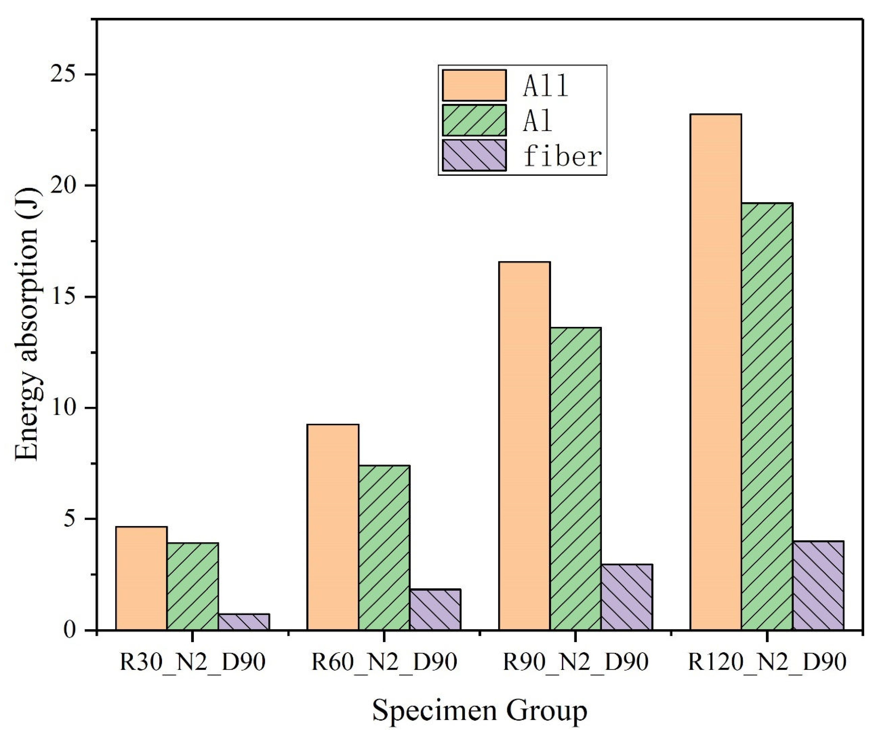
4.1.2. Influence of Curvature on CARALL Energy Absorption

Figure 16 shows the energy absorption of CARALL. “All” represents the total energy absorption amount of the specimen, “Al” represents the energy absorption amount of the aluminum alloy laminates, and “fiber” represents the energy absorption amount of the fiber laminates. As the radius of curvature increases, the energy absorption of the whole structure increases. The energy absorption of the aluminum plate increases with the increase in the curvature radius, and accounts for the main part of the energy absorption of structure. The energy absorption of the fiber layer is about one-quarter that of the metal layer. The energy absorption distribution of each fiber layer is shown in Figure 17. Layer1 is the outermost layer. In general, the energy absorption of fiber is less for a small radius of curvature, while the failure mode of fiber is more complicated for a large radius of curvature, which has strong randomness. Compared with the inner fiber, the outer fiber has more energy absorption, and the difference increases with the increase in the radius of curvature.

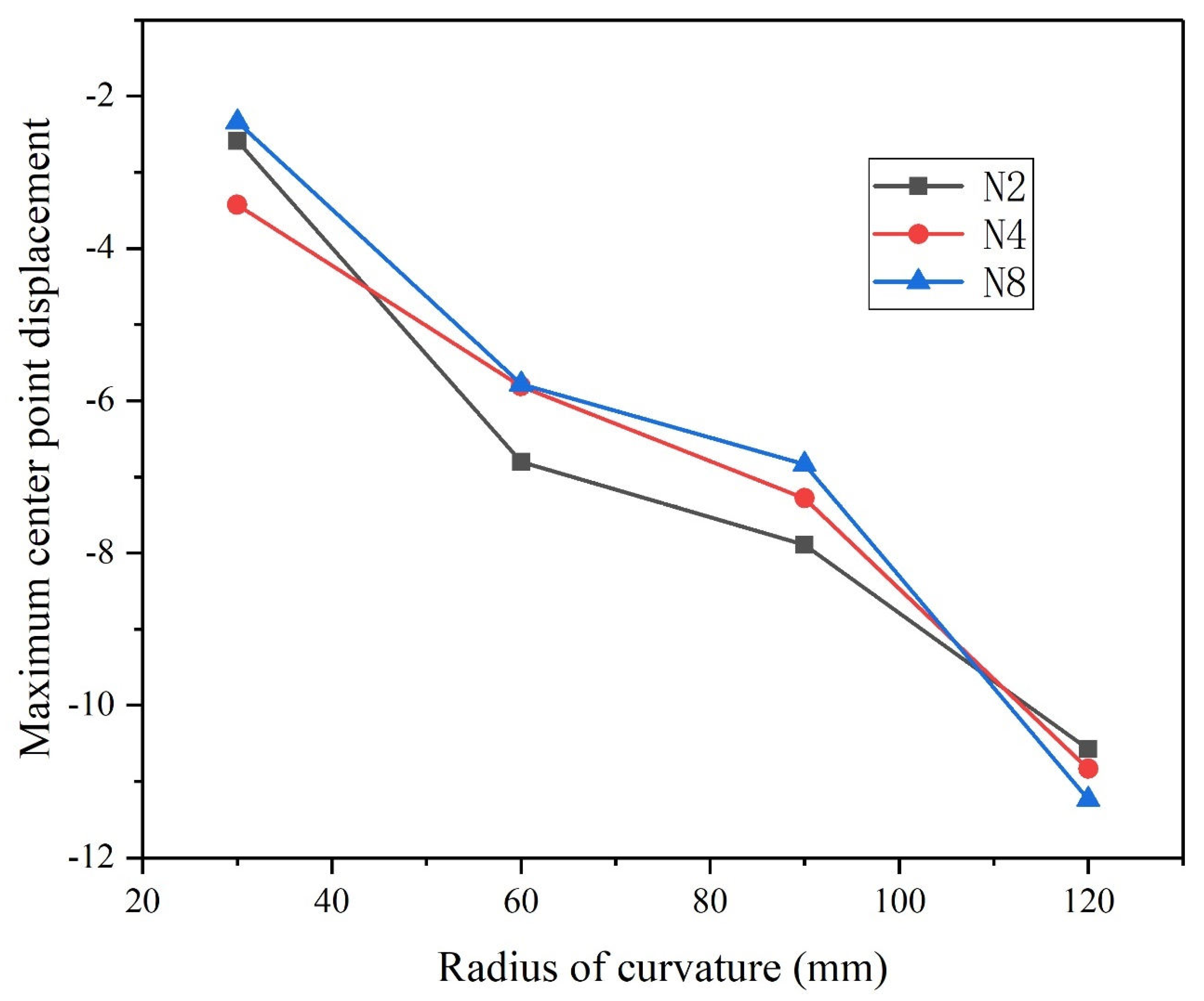
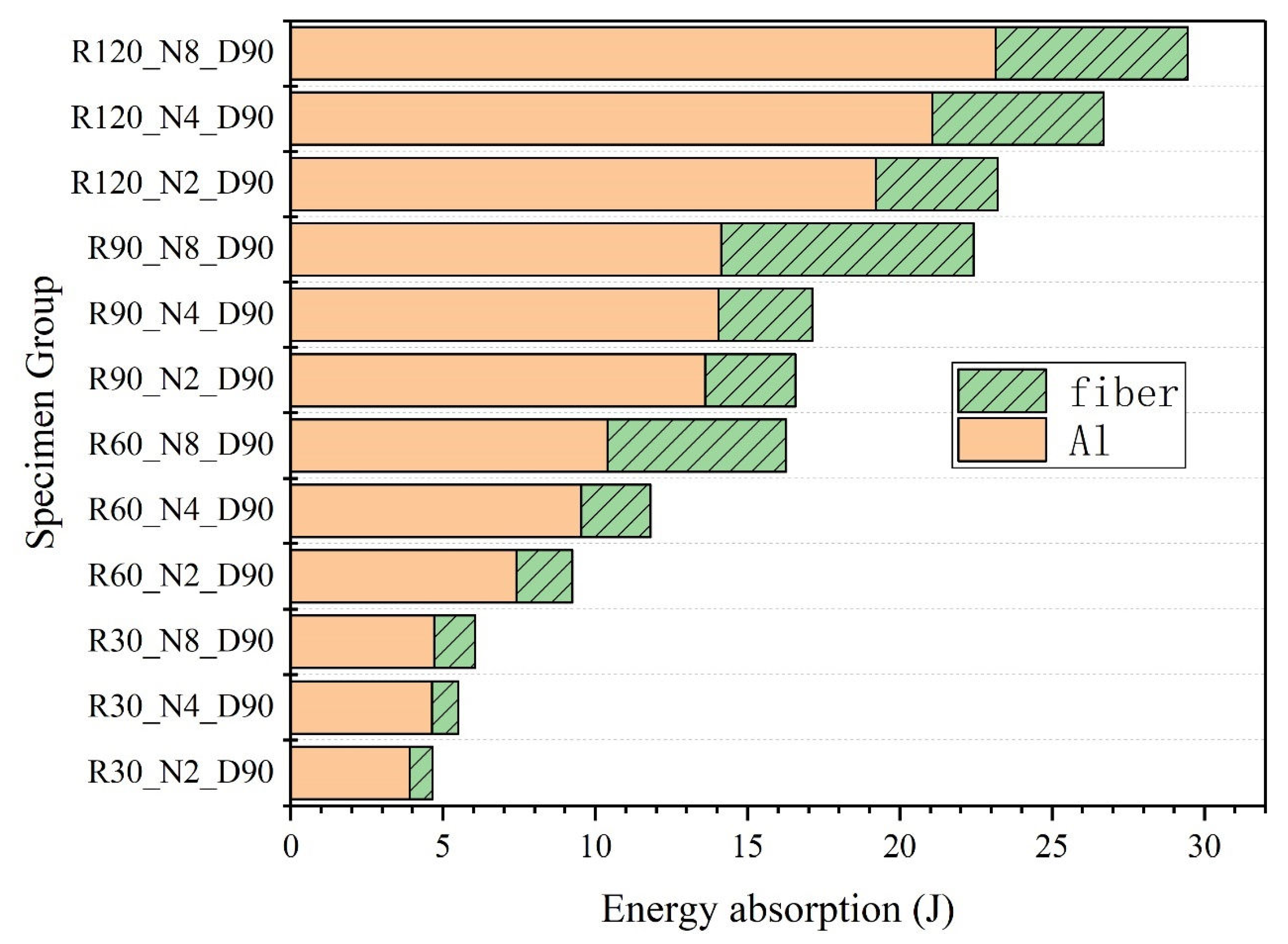
4.2. Influence of Layers on CARALL Impact Response of Curved Surface

According to the classification of multi-layer FML structure in the figure, three kinds of layering methods, i.e., N = 2, N = 4, N = 8, and four kinds of curvature, i.e., R = 20, R = 60, R = 90, R = 120, were studied. The contour diagram of maximum deformation time is shown in Figure 18.
As shown in Figure 18, when the structure curvature radius is small (R30 group), the number of layers has no obvious effect on the failure mode of structure deformation, and the matrix fracture failure near the clamping edge is the main failure mode of the fiber layer. With the increase in the curvature radius (R60 group, R90 group), the number of fiber fractures increases as the number of structural layers increases. The fault distribution area expands from near the center to the whole structure. Meanwhile, delamination failure increases. This is because when the number of layers increases, the number of single-layer fibers decreases, and the fiber is more likely to break. At the same time, because there is no continuity between the multilayer fibers (aluminum plate partition), the location of the fault zone between each fiber layer increases, and the overall fiber dimension fault zone increases. When the structure curvature radius is large (R = 120 group), with the increase in the number of layers, the number of fiber fractures increases, and the matrix fracture failure increases; furthermore, there are many axial matrix fractures, and the number of layers and the volume of layers increases. As shown in Figure 19, the maximum deformation of the structure does not change significantly with the increase in the number of fiber layers, and the radius of curvature of the structure is still the main factor affecting the maximum deformation.
The influence of the number of layers on structural energy absorption is shown in Figure 20. “All” represents the total energy absorption amount of the specimen, “Al” represents the energy absorption amount of the aluminum alloy laminates, and “fiber” represents the energy absorption amount of the fiber laminates. Under the curvature of a single structure, the total amount of structural energy absorption increases with the increase in the number of layers. There is no significant change in the energy absorption of the aluminum plate layer, while the energy absorption of the fiber layer increases more. Since the aluminum plate absorbs the impact energy through plastic deformation, its energy absorption is positively correlated with the maximum deformation at the center, and the number of different layers has no great influence on the maximum deformation at the center, so the number of layers has no great influence on the energy absorption of the aluminum plate. Fiber layer energy absorption mainly occurs due to fiber fracture, matrix fracture, and interlayer stratification. When the structural lamination increases, the number of fiber fractures increases, the number of matrix fractures increases, and the number of laminations and the area of lamination increase, so the energy absorption of the fiber layer increases. Therefore, when other structural parameters remain unchanged, increasing the number of failure layers can increase the number of failures and the failure area of fiber layers, thus improving the energy absorption characteristics of the structure.

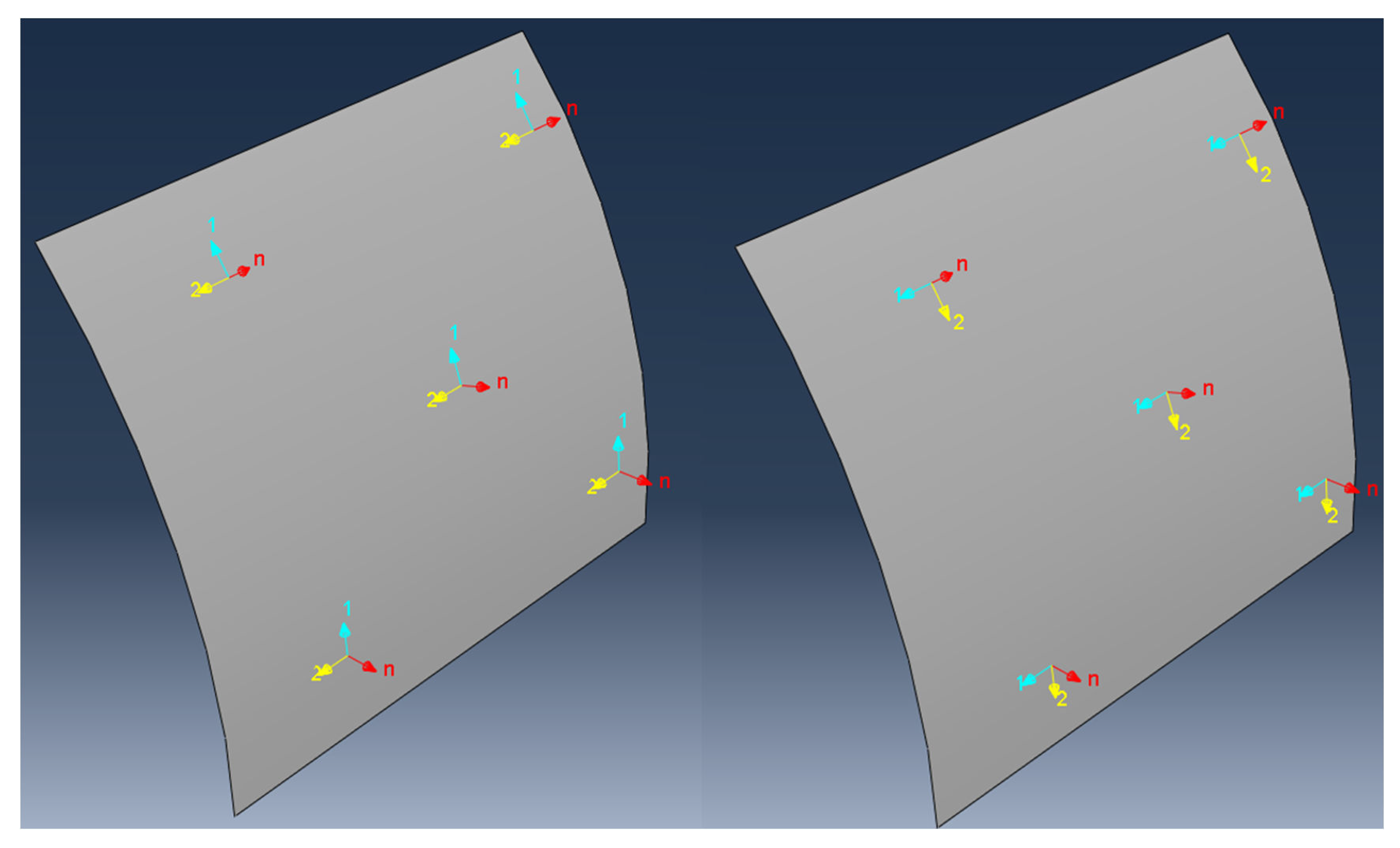
4.3. Influence of Fiber Layering Direction on CARALL Impact Response of Curved Surfaces

In planar CARALL structures, the fiber lamination direction is the most important structural characteristic of the fiber structure, and has a decisive effect on the failure mode and impact resistance of the fiber. However, in a curved surface structure, the coupling between the influence of the fiber arrangement direction and the curved surface structure is more complex. In this paper, the impact response of double-layer fibers under different radii of curvature is studied according to the change in the one-way layering angle [0, 30, 45, 90] and orthogonal arrangement (X).
Figure 21 shows the comparison of CARALL deformation modes of double layers with different fiber layering directions.
D0 arrangement (along the circumferential direction): under the small radius of curvature (R = 30 mm), the matrix fracture zone along the circumferential direction appears in the fiber layer. With the increase in curvature, the number of fiber fracture zones along the axial direction increases.
D30 arrangement: under the small radius of curvature (R = 30), the fiber layer is mainly fractured by the clipped edge matrix. With the increase in curvature, the fiber layer appears to be axial and axial fractures occur between the fiber and the matrix.
D45 arrangement: in this arrangement, the fiber layer has more complex fiber failure. Fractures of the fiber and matrix appear along the axial direction and circumferential clamping edges. Multiple fault zones appear in the center. With the increase in curvature radius, the number of fault zones and the degree of fracture increase.
D90 arrangement (along the axial direction): under the small radius of curvature, there are many obvious matrix fractures along the axial direction. This is because the structural deformation is mainly sagging deformation, and the matrix is subjected to strong shear and tensile stress at the edge of sag. With the increase in the radius of curvature, both the fiber fracture along the circumferential clipping edge and the matrix cracking along the axial direction increase. This is because with the increase in the radius of curvature, the overall bending deformation of the structure is dominant, and the shear stress of the clipped edge material increases.
The DX arrangement is a bidirectional orthogonal arrangement. Under the small radius of curvature, the fiber layer arranged along the circumference can provide strong bending resistance, and prevent the matrix fracture of the fiber layer arranged along the axial direction. Due to the good anisotropy of the bidirectional arrangement, neat fiber or matrix fracture cannot easily occur in the fiber layer, and only scattered failure occurs.
The maximum center point displacement and corresponding energy absorption of double-layer CARALL with different layering angles and radii of curvature are shown in Figure 22 and Figure 23.
Under the same radius of curvature, D0 and DX have the minimum deformation, and D45 has the maximum deformation. With the increase in curvature radius, the difference between the maximum and minimum deformation increases, while the corresponding energy absorption shows the opposite trend or pattern.

5. Conclusions

In this paper, the dynamic mechanical responses of carbon fiber reinforced aluminum alloy laminates with different radii of curvature, numbers of layers, and layering methods under external explosion loading were investigated. The simulation results have guiding significance for the optimization design of fiber reinforced composite structures under external explosion loading. The conclusions can be summarized as follows:
(1)
The results show that the curvature radius has the most direct effect on the structural deformation failure. With the decrease in the curvature radius, the displacement of the center point of the backplane decreases, but the energy absorption of the shock wave also decreases. With the increase in the radius of curvature, the absorption energy of the aluminum alloy layer increases significantly and plays a major role.
(2)
Parametric study shows that the layered structure has little effect on the deformation of the structure. In contrast, the increase in the number of layered structures will significantly improve the energy absorption of the shock wave. With the increase in the radius of curvature, the influence will be more significant. In the multilayer fiber energy absorption, the outer fiber has more energy absorption, and the difference increases with the increase in curvature radius.
(3)
The fiber layering mode determines the failure mode and impact resistance of the fiber. Under the same curvature radius, the 0° and orthogonal arrangements of the fiber layer have the minimum deformation, and the 45° arrangement has the maximum deformation. With the increase in curvature radius, the difference in the deformation of different arrangement modes increases. The energy absorption of the shock wave shows the opposite rule.

Author Contributions

Conceptualization, B.Z. and S.F.; methodology, S.F.; software, B.Z.; validation, B.Z.; formal analysis, B.Z.; investigation, B.Z.; resources, S.F.; data curation, B.Z.; writing—original draft preparation, B.Z.; writing—review and editing, B.Z.; visualization, B.Z.; supervision, S.F.; project administration, S.F.; funding acquisition, S.F. All authors have read and agreed to the published version of the manuscript.

Funding

This research received no external funding.

Conflicts of Interest

The authors declare no conflict of interest.

References

  1. Sadeghi, M.; Alderliesten, R.C.; Benedictus, R. Impact resistance of fiber-metal laminates: A review. Int. J. Impact Eng. 2012, 49, 77–90. [Google Scholar] [CrossRef]
  2. Zarei, H.; Fallah, M.; Minak, G.; Bisadi, H.; Daneshmehr, A. Low velocity impact analysis of Fiber Metal Laminates (FMLs) in thermal environments with various boundary conditions. Compos. Struct. 2016, 149, 170–183. [Google Scholar] [CrossRef]
  3. Li, X.; Yahya, M.Y.; Bassiri Nia, A.; Wang, Z.; Lu, G. Dynamic failure of fibre-metal laminates under impact loading–experimental observations. J. Reinf. Plast. Compos. 2016, 35, 305–319. [Google Scholar] [CrossRef]
  4. Hinton, M. Failure Criteria in Fibre-Reinforced-Polymer Composites; Elsevier Science: Amsterdam, The Netherlands, 2004. [Google Scholar]
  5. Wang, B.; Wu, L.Z.; Ma, L. Low-velocity impact characteristics and residual tensile strength of carbon fiber composite lattice core sandwich structures. Compos. Part B Eng. 2011, 42, 891–897. [Google Scholar] [CrossRef]
  6. Wang, S.X.; Wu, L.Z.; Ma, L. Low-velocity impact and residual tensile strength analysis to carbon fiber composite laminates. Mater. Des. 2010, 31, 118–125. [Google Scholar] [CrossRef]
  7. Chai, G.B.; Manikandan, P. Low velocity impact response of fibre-metal laminates–A review. Compos. Struct. 2014, 107, 363–381. [Google Scholar] [CrossRef]
  8. Su, X.; Yang, Z.; Liu, G. Finite element modelling of complex 3d static and dynamic crack propagation by embedding cohesive elements in abaqus. Acta Mech. Solida Sin. 2010, 23, 271–282. [Google Scholar] [CrossRef]
  9. Xu, M.M.; Huang, G.Y.; Feng, S.S.; McShane, G.J.; Stronge, W.J. Perforation resistance of aluminum/polyethylene sandwich structure. Mater. Des. 2016, 100, 92–101. [Google Scholar] [CrossRef] [Green Version]
  10. Che, L.; Fang, G.; Wu, Z.; Ma, Y.; Zhang, J.; Zhou, Z. Investigation of curing deformation behavior of curved fiber metal laminates. Compos. Struct. 2020, 232, 111570. [Google Scholar] [CrossRef]
  11. Sinmazçelik, T.; Avcu, E.; Bora, M.Ö.; Çoban, O. A review: Fibre metal laminates, background, bonding types and applied test methods. Mater. Des. 2011, 32, 3671–3685. [Google Scholar] [CrossRef]
  12. Song, S.H.; Byun, Y.S.; Ku, T.W.; Song, W.J.; Kim, J.; Kang, B.S. Experimental and Numerical Investigation on Impact Performance of Carbon Reinforced Aluminum Laminates. J. Mater. Sci. Technol. 2010, 26, 327–332. [Google Scholar] [CrossRef]
  13. Rahmani, H.; Eslami-Farsani, R.; Ebrahimnezhad-Khaljiri, H. High velocity impact response of aluminum-carbon fibers-epoxy laminated composites toughened by nano silica and zirconia. Fibers Polym. 2020, 21, 170–178. [Google Scholar] [CrossRef]
  14. Bahari-Sambran, F.; Eslami-Farsani, R.; Arbab Chirani, S. The flexural and impact behavior of the laminated aluminum-epoxy/basalt fibers composites containing nanoclay: An experimental investigation. J. Sandw. Struct. Mater. 2020, 22, 1931–1951. [Google Scholar] [CrossRef]
  15. Najafi, M.; Ansari, R.; Darvizeh, A. Influence of thermal aging on mechanical properties of fiber metal laminates hybridized with nanoclay. Proc. Inst. Mech. Eng. Part C J. Mech. Eng. Sci. 2019, 233, 7003–7018. [Google Scholar] [CrossRef]
  16. Najafi, M.; Ansari, R.; Darvizeh, A. Effect of cryogenic aging on nanophased fiber metal laminates and glass/epoxy composites. Polym. Compos. 2019, 40, 2523–2533. [Google Scholar] [CrossRef]
  17. Askin, M.Y.; Turen, Y. The effect of GNP addition on mechanical and residual stress properties of 2024-T3 aluminum and carbon fiber reinforced FML. Mater. Res. Express 2019, 6, 126546. [Google Scholar] [CrossRef]
  18. Majerski, K.; Surowska, B.; Bienias, J. The comparison of effects of hygrothermal conditioning on mechanical properties of fibre metal laminates and fibre reinforced polymers. Compos. Part B Eng. 2018, 142, 108–116. [Google Scholar] [CrossRef]
  19. Ebrahimnezhad-Khaljiri, H.; Eslami-Farsani, R.; Akbarzadeh, E. Effect of interlayer hybridization of carbon, Kevlar, and glass fibers with oxidized polyacrylonitrile fibers on the mechanical behaviors of hybrid composites. Proc. Inst. Mech. Eng. Part C J. Mech. Eng. Sci. 2019, 234, 1823–1835. [Google Scholar] [CrossRef]
  20. Eslami-Farsani, R.; Aghamohammadi, H.; Khalili, S.; Ebrahimnezhad-Khaljiri, H.; Jalali, H. Recent trend in developing advanced fiber metal laminates reinforced with nanoparticles: A review study. J. Ind. Text. 2020, 51, 7374S–7408S. [Google Scholar] [CrossRef]
  21. Xu, M.M. Velocity High Impact Resistance of Carbon Fiber-Reinforced Metal Laminates; Beijing Insititute of Technology: Beijing, China, 2016. [Google Scholar]
  22. Yao, L.; Sun, G.; He, W.; Meng, X.; Xie, D. Investigation on impact behavior of FMLs under multiple impacts with the same total energy: Experimental characterization and numerical simulation. Compos. Struct. 2019, 226, 111218. [Google Scholar] [CrossRef]
  23. Lin, X.H. Study on Impact Resistance of Fiber-Metal Laminates; Huazhong University of Science and Technology: Wuhan, China, 2012. [Google Scholar]
  24. Lee, D.W.; Park, B.J.; Park, S.Y.; Choi, C.-H.; Song, J. Fabrication of High-Stiffness Fiber-Metal Laminates and Study of Their Behavior Under Low-Velocity Impact Loadings. Compos. Struct. 2018, 189, 61–69. [Google Scholar] [CrossRef]
  25. Hu, Y.; Zhang, Y.; Fu, X.; Hao, G.; Jiang, W. Mechanical properties of Ti/CF/PMR polyimide fiber metal laminates with various layup configurations. Compos. Struct. 2019, 229, 111408. [Google Scholar] [CrossRef]
  26. Anisimov, A.G.; Müller, B.; Sinke, J.; Groves, R.M. Analysis of thermal strains and stresses in heated fibre metal laminates. Strain 2018, 54, e12260. [Google Scholar] [CrossRef]
  27. Ebrahimnezhad-Khaljiri, H.; Eslami-Farsani, R. Experimental investigation of flexural properties of glass fiber–epoxy self-healable composite structures containing capsulated epoxy healing agent and NiCl2(imidazole)4 catalyst. J. Ind. Text. 2019, 51, 788–805. [Google Scholar] [CrossRef]
  28. Prasad, E.; Sivateja, C.; Sahu, S. Effect of nanoalumina on fatigue characteristics of fiber metal laminates. Polym. Test. 2020, 85, 106441. [Google Scholar] [CrossRef]
Figure 1. Schematic diagram of the CARALL simulation model.
Applsci 13 04906 g001
Figure 2. Definition of fiber layup direction.
Applsci 13 04906 g002
Figure 3. Simplified clamping device.
Applsci 13 04906 g003
Figure 4. Model meshing.
Applsci 13 04906 g004
Figure 7. Viscous contact progressive damage behavior of the secondary stress separation criterion.
Applsci 13 04906 g007
Figure 8. Stiffness degradation model of linear elastic materials.
Applsci 13 04906 g008
Figure 9. Comparison between experimental and simulation deformation modes.
Applsci 13 04906 g009
Figure 10. A comparison of the deformation and failure patterns of the aluminum panel of experiment results and numerical prediction.
Applsci 13 04906 g010
Figure 11. Comparison between the experimental and numerical predicted maximum central deflection of aluminum panel.
Applsci 13 04906 g011
Figure 12. Deformation–time history diagram of double-layer CARALL structures with different radii of curvature.
Applsci 13 04906 g012
Figure 13. Comparison of deformation history and maximum deformation of CARALL center with different radii of curvature: (a) central point displacement–time; (b) cloud diagram of backplane.
Applsci 13 04906 g013aApplsci 13 04906 g013b
Figure 14. Failure mode of the fiber layer with a small radius of curvature.
Applsci 13 04906 g014
Figure 15. Failure mode of fiber with a large radius of curvature.
Applsci 13 04906 g015
Figure 16. Global energy distribution.
Applsci 13 04906 g016
Figure 17. Fiber layer energy distribution.
Applsci 13 04906 g017
Figure 18. Influence of layers on CARALL deformation failure modes of curved surfaces.
Applsci 13 04906 g018
Figure 19. The influence of the number of layers on the maximum deformation of the central point.
Applsci 13 04906 g019
Figure 20. The influence of the number of layers on the energy absorption of each structure.
Applsci 13 04906 g020
Figure 21. Comparison of deformation modes at the maximum center deformation time of double-layer CARALL with different fiber arrangements.
Applsci 13 04906 g021
Figure 22. Maximum deformation vs. fiber layering direction and radius of curvature.
Applsci 13 04906 g022
Figure 23. Energy absorption vs. fiber layering direction and radius of curvature.
Applsci 13 04906 g023
Table 1. Different FML structures parameter table.
Parameter NameValue
Radius of curvature R(mm)30, 60, 90, 120
The layer number N2,4,8
Fiber direction D (°)unidirectional [0, 30, 45, 90] orthogonal (X)
The following sample naming rules are formulated: R30_N4_D90 means the radius of curvature is 30 mm and the number of layers is 4, using circumferential layering.
Table 2. Contact parameters.
Knn (GPa)Kss (GPa)Ktt (GPa) t n o (MPa) t s o (MPa) t t o (MPa)
fiber-fiber5.23.913.91713030
fiber-alloy3.53.53.5353939
Table 3. Material parameters [24].
Density (kg/m3)Young’s Modulus (GPa)Yield Stress (MPa)Poisson’s RatioTangent Modulus (GPa)
Al-202426807275.80.330.737
Table 4. T700s mechanical properties of unidirectional carbon fiber plate [21].
Value
ρ (kg/m3) 1750
E11 (GPa) 134
E22 = E33 (GPa) 5.2
𝜈12 = 𝜈31 0.25
𝜈23 0.38
G12 = G13 = G23 (GPa) 3.1
Xt (MPa) 2160
Xc (MPa) 1470
Yt = Zt (MPa) 71
Yc = Zc (MPa) 1030
S12 (MPa) 450
S31 = S32 (MPa) 325
Table 5. Degradation coefficient under different failure modes [21].
Failure ModeE11E22E33G12G13G23ν12ν13ν23
Fiber tensile failure0.070.070.070.070.070.070.070.070.07
Fiber compression failure0.140.140.140.140.140.140.140.140.14
Matrix tensile failure10.20.200.20.20.2111
Matrix compression failure10.40.40.40.40.4111
In-plane shear failure111011011
Out-of-plane shear failure111100100
Disclaimer/Publisher’s Note: The statements, opinions and data contained in all publications are solely those of the individual author(s) and contributor(s) and not of MDPI and/or the editor(s). MDPI and/or the editor(s) disclaim responsibility for any injury to people or property resulting from any ideas, methods, instructions or products referred to in the content.

