Abstract
In this article, a new methodology for the sizing of a fast-charging station for electric vehicles is presented. The proposed method is applicable to public service vehicles on urban journeys. Its use has been conceived for vehicles equipped with an energy storage system based on supercapacitors (SCs), which are already functional in several countries. The proposed charging station also uses a bank of SCs of variable capacitance. During the study, mathematical expressions will be obtained for the electrical variables involved in vehicle charging: instantaneous current, peak current, charging time, dissipated energy, and the efficiency of energy transference. From these, each of the components of the system will be dimensioned: the capacitance of the charger with its different variable steps, the initial voltage of the charger, and the current smoothing inductor. The proposed charger presents the advantage of allowing energy to be evacuated to the electric vehicle very quickly and with high performance, all without using an external power source or high-power converters. The proposed architecture minimizes the disturbances that, with conventional methods, would appear on the electrical grid, preventing the installation of fast-charging stations at many grid nodes, as is currently the case. Finally, the charger control algorithm is considerably simplified as it only depends on the initial voltage of the vehicle’s accumulator.
1. Introduction
Supercapacitors (SCs) are electrical energy storage devices characterized by their high efficiency and specific power. Both properties are due to the fact that the energy is stored in the form of an electric field, which, together with their low internal resistance, makes them capable of charging and discharging at very high currents. In addition, they endure several orders of magnitude more charging and discharging cycles than other storage systems [1], making them ideal for hybrid systems when combined with batteries or fuel cells [2,3,4,5,6]. SCs are used in the accumulators of different types of vehicles [7,8]. Their use is particularly effective in cases where urban journeys with multiple stops are made. In this type of tour, much more energy can be recovered by regenerative braking, and they can be charged extremely quickly compared to electrochemical accumulators. In addition, the high discharge current provides the vehicle with greater acceleration on start-up. On the other hand, SCs are lighter than conventional batteries, thus reducing the overall weight of the vehicle and with it, its energy consumption. The above advantages have made electric urban transport vehicles using SCs an increasingly attractive option [9,10]. Public transport buses or urban solid waste collection trucks, which follow a fixed route, at slow speeds, with multiple accelerations and decelerations, are the cases where the use of SC-based accumulators is optimal, as long autonomies between successive stops are not required [11].
The main drawback of SCs compared to batteries is their lower energy density, which reduces the range of vehicles whose accumulators use them; however, in the case of urban transport, this disadvantage can be easily solved by installing fast chargers along the route. The time it takes for passengers to get in and out of the vehicle (20–30 s) is more than enough if the charging station is able to supply the necessary current. Recharging at the exit of the stop would then make it possible to reach the next charging station to repeat the process.
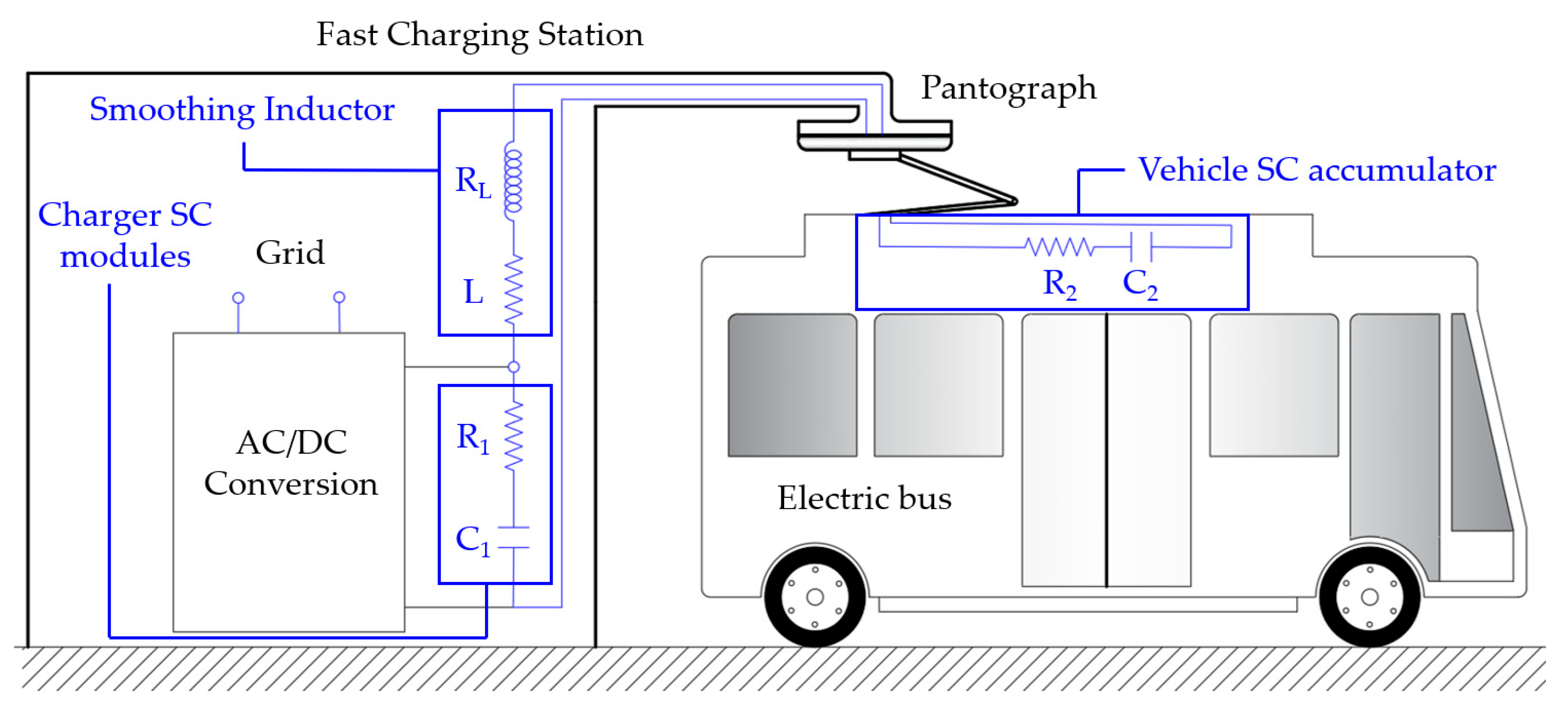
There are multiple types of electronic converters with different control strategies for fast charging of SCs [12,13,14]. However, due to their topologies and the high powers they have to handle, they can cause disturbances in the electrical grid [15], such as voltage drops, voltage dips, flickering, or harmonic distortion, which can only be solved, in some cases, by modifying the grid itself. Therefore, in recent years, several studies have been carried out to develop new technologies for fast-charging stations, [16,17,18,19,20,21] that minimize the disturbances mentioned above. One of the most interesting and efficient alternatives is precisely the use of SCs as an energy storage medium [18,19,20]. Its operating principle is very simple: a bank of SCs, slowly charged from the grid, can evacuate its energy to the vehicle’s accumulator, also built with SCs, very quickly. Once the vehicle has been charged, the SCs in the station are slowly recharged, absorbing a low level of power that does not cause any disturbance. After this slow charging process, the system is ready for the fast charging of the next vehicle arriving at the station. Figure 1 shows a general scheme of the fast-charging station in which the bank of SCs of the charger (C1, R1), that of the vehicle (C2, R2), and the smoothing inductor between them (L, RL) are represented. As can be seen, charging is done directly between the two SCs banks without the need for an intermediate DC–DC converter. In addition to the advantages this represents for the grid, the charger is simplified and cheaper, since only one inductor is required between the two sets of SCs to limit the charging current.
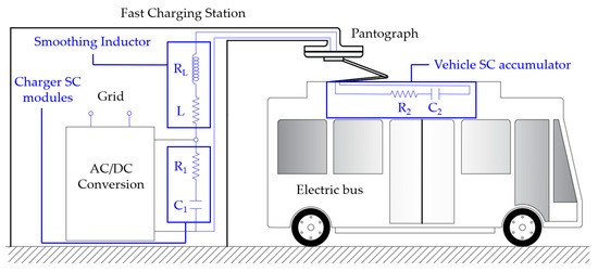
Figure 1.
Simplified schematic of a bus connected to a fast-charging station built with SCs.
Later sections will show, in depth, the simplicity of the charging station architecture compared to the use of power converters. If more than one vehicle is to be charged simultaneously, it would be sufficient to replicate the circuit of Figure 1. Even with simultaneous charging in multiple recharge points of the station, no disturbances would appear in the grid.
Since the main complexity of this type of charger lies in establishing the characteristics of the banks of SCs and the inductor, this study will present a method for sizing all of their components. First of all, the mathematical expressions of all the electrical variables involved in vehicle charging, namely the current, internal voltages, maximum charging time, energy dissipated, and the efficiency of the charging process, will be obtained. Then, each of its components will be sized. The calculation of the smoothing inductor is complex; therefore, a graphical method will be presented that guarantees that the assembly functions correctly for any initial voltage (remaining energy) of the vehicle’s accumulator considering, in addition, the degree of aging that all the SC cells may undergo.
The paper has been organized in the following sections: Section 2.1 will show the mathematical analysis of the main electrical variables: current, i(t); internal voltages of the charger, u1(t), and of the vehicle accumulator, u2(t); maximum time set for charging, tcharge; limit current, Imax; energy dissipated during the transient period, wd(t); and efficiency of the charging process, ε(%). Section 2.2 will thoroughly describe the process of selecting the capacitance of the charger, which consists of several identical modules connected in parallel. A procedure to calculate their initial voltage in order to maximize efficiency, a graphical method for the proper selection of the smoothing inductor, and the values of its inductance and internal resistance will also be presented. In Section 3, a practical case study for a Tecnobus Gulliver U500™ prototype electric bus, whose storage system consists of lead-acid batteries and an array of SCs, will be analyzed. Section 4 will finally show the conclusions of the study.
2. Materials and Methods
2.1. Electrical Analysis of an SC Working in a Fast-Charging System
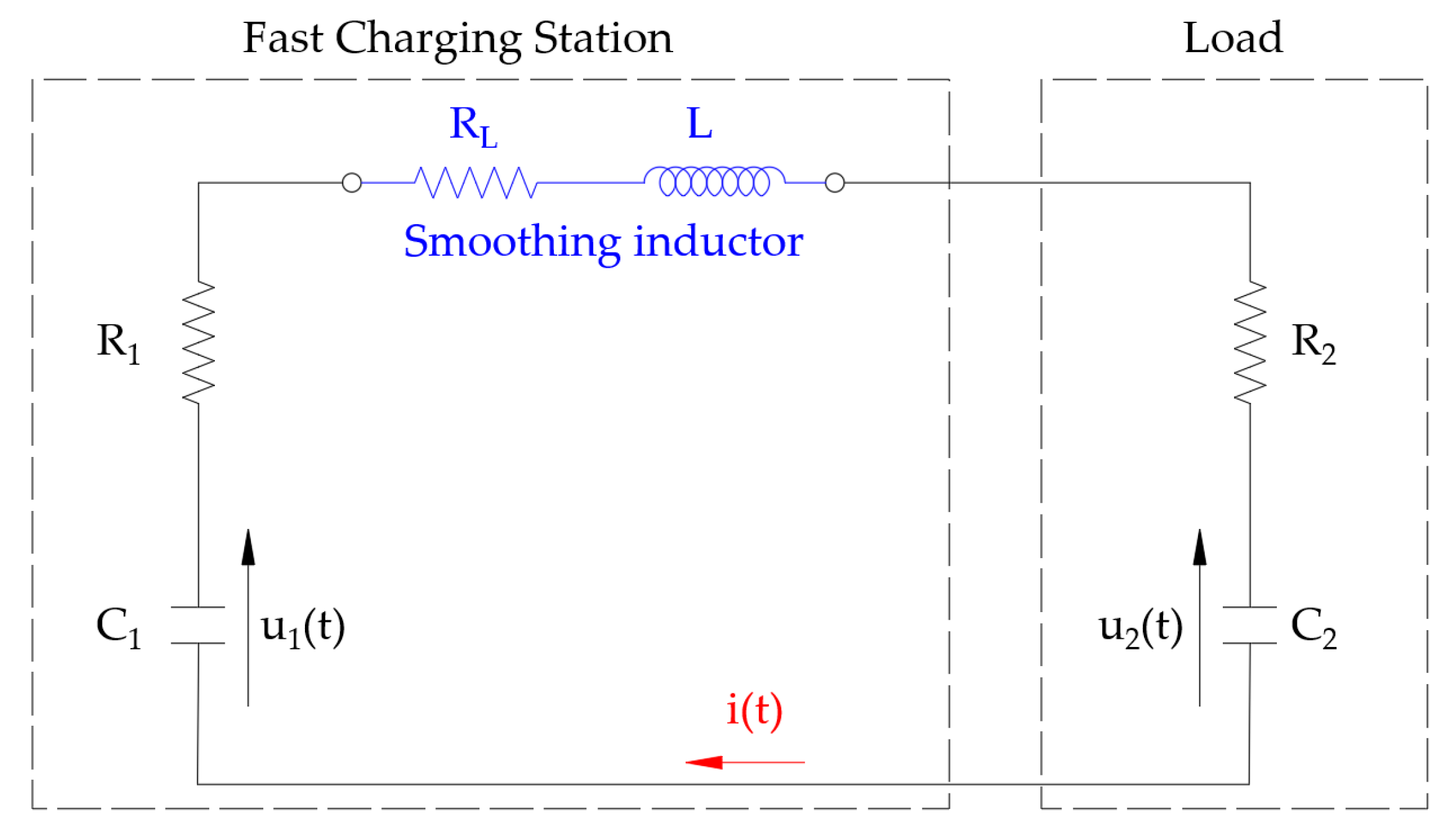
In this section, the study of the evolution of current in the charging station, as shown in Figure 2, will be presented. For this purpose, the RC series model of SCs will be used. This model is the most widely used for sizing [22,23,24,25,26,27] and provides simple analytical expressions when studying constant power and charging or discharging processes [28,29,30]. The SC resistance and capacitance values are provided by the manufacturers from standardized tests. The SC bank operating as a generator shall be considered to have an internal resistance and capacitance of R1 and C1 (variable), and the vehicle SC array, operating as a load, shall be considered to have a resistance and capacitance of R2 and C2 (constant). An inductor must be installed between them to limit the current when the charger is switched on. The value of its internal resistance will be taken to be RL. It will be assumed that the charger starts from a fixed initial voltage, U01, and that the load starts from an initial voltage, U02, which is lower than the previous one and can be variable, since the vehicle during its journey, depending on the number of passengers or the distance traveled, may have consumed more or less energy.
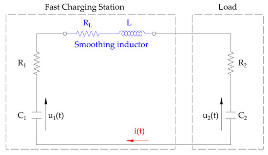
Figure 2.
Wiring diagram of the fast-charging station.
2.1.1. Circuit Current and SC Voltages
Applying Kirchhoff’s voltage law and considering the relationship between the SC voltages and the circuit current, the following second order differential equation can be defined for the calculation of the current, i(t):
RT being the total resistance of the circuit,
and Ceq being the equivalent capacitance,
As there are no generators in the circuit, the solution of the homogeneous differential equation and the complete differential equation will be the same. The two solutions of the homogenous characteristic equation are the following:
α being the damping coefficient (s−1),
and ω0 being the angular resonance frequency (s−1), which only depends on the inductance and the total capacitance:
β(s−1) is defined as follows:
Depending on the type of solution, −α ± β, of the differential equation, the system can be underdamped, critical, or overdamped. In this application, the values of RT, L, and Ceq must be chosen so that the system is always overdamped. In the first case the voltage would suffer oscillations that could exceed the maximum admissible voltage of the SC arrays. The second is the inflection point between the first and third, which in practice cannot occur, so only the strict underdamping situation should be avoided. In addition, if the system were underdamped, there would be time instants where the vehicle’s accumulator would inject current into the charging station, which is incompatible with the normal operation of the system.
To solve (1), the initial voltages of C1 and C2 must be known. By defining u1 (t = 0) = U01 and u2 (t = 0) = U02, being that U01 > U02, and ΔU = U01 − U02, the following solution for the circuit current expressed as a function of the parameters α and β is obtained:
C1 and C2 voltages, u1(t) and u2(t), are directly calculated from (8):
When the circuit reaches the steady state, both SC arrays will have the same voltage value:
The final voltage, Ufinal, only depends on the capacitances of C1 and C2 and their initial voltages, U01 y U02.
2.1.2. Charging Time and Maximum Current
The value of the inductance must be chosen as a function of the charging time and the peak current during the transient state. As can be deduced from (8), the transient current consists of two decreasing exponential functions, it will, therefore, die out when the slower component has done so. The time constant of the circuit, τ(s), can be assumed to be as follows:
Considering that a period 7 times longer than τ is sufficient for the transient current to extinguish, it is possible to define the maximum time for charging, tcharge, as follows:
One of the requirements to be imposed for calculating the inductance value is that tcharge shall not exceed a certain value, which shall be set at the design stage. To calculate the instant at which the maximum current occurs, the current shall be derived with respect to time and equaled to zero as follows:
The time instant, tImax, at which the transient current reaches its maximum value is therefore
If this value is entered in (8), the peak current, Imax, will be obtained as follows:
For the sake of simplicity, a new dimensionless constant, γ, will be defined as
In an overdamped system, it will be satisfied when γ > 1, since α > β.
2.1.3. Power and Energy Dissipated during the Charging Process
The total power dissipated in all components, pd(t), can be calculated from (8), where
Its integration will result in the instantaneous energy dissipated, wd(t), where
Once the charging process is completed, the exponential functions are negligible, and the total dissipated energy, Wd_total, can be expressed as follows:
Replacing in (20) α and β, calculated in (5) and (7), Wd_total can be simplified as
An interesting conclusion is thus reached; the energy dissipated only depends on the equivalent capacitance and initial voltages but not on the resistance of the circuit.
2.1.4. Efficiency of the Charging Process
The efficiency of the energy transference between the charger and the vehicle accumulator, ε(%), can be defined as follows:
By using (11), the efficiency simplifies as follows:
As it can be deduced from (23), the efficiency only depends on the initial voltages of the charger, vehicle SCs bank, and the final voltage of both. The higher the initial voltage of the charger, U01, the lower the efficiency; therefore, it is desirable that the charger presents an initial voltage that is as low as possible. Similarly, the higher the initial voltage of the vehicle SC bank, U02, the higher the efficiency.
2.2. Calculation of the Value of the Variables Involved in the Charging Process
This section will show how to calculate the values of the resistance and capacitance of the charger, (R1 and C1), resistance and inductance of the smoothing inductor, (RL and L) and the initial voltage of the charger, U01. It will be assumed that, upon arrival of the vehicle at the charging station, the bank of SCs of the charger presents it maximum voltage, U01, and is ready for charging. For this to occur, the estimated time that will elapse between charging one vehicle and the next one must be carefully studied, so that the charger has time to reach its maximum voltage. This time will depend on other variables, which are not the subject of this study.
The variables of the vehicle’s bank of SCs, (R2 and C2), will be assumed to be known, as well as its rated voltage, U2N; however, its initial voltage, U02, may take any value less than or equal to U2N. Following the recommendation of the SCs’ manufacturers, who advise that the cells should never be discharged below 50% of their rated voltage, it will be considered that the initial voltage of the vehicle’s SC bank will take values within the following range: 0.5U2N ≤ U02 ≤ 0.8U2N. The values of R2 and C2 shall be assumed to have been selected by the vehicle’s manufacturer so that, with one prior tour at the time of charging, their voltage is never above 0.8U2N. This assumption is very conservative as it implies charging when only 20% of the available energy has been consumed, something that is very unlikely.
2.2.1. Selection of the Charger Capacitance and Its Initial Voltage
Commercial SCs can endure a voltage slightly above the maximum for short periods of time. For example, a typical 2.7 V cell can be used with a voltage of 2.85 V for a restricted time. This limiting value shall be designated as U2Nmax. The initial voltage of the charger shall be taken equal to this limit value, U01 = U2Nmax, or slightly lower. As there is a voltage drop during the charging process, the final value of the voltage of the vehicle´s accumulator (Ufinal) will always be below U2Nmax, thus maintaining the safety of the cells as well as the maximum charging voltage.
Once the value of U01 has been set, the following relationship between the capacitances must exist for the voltages of the SCs to converge to a final value, Ufinal, according to (11):
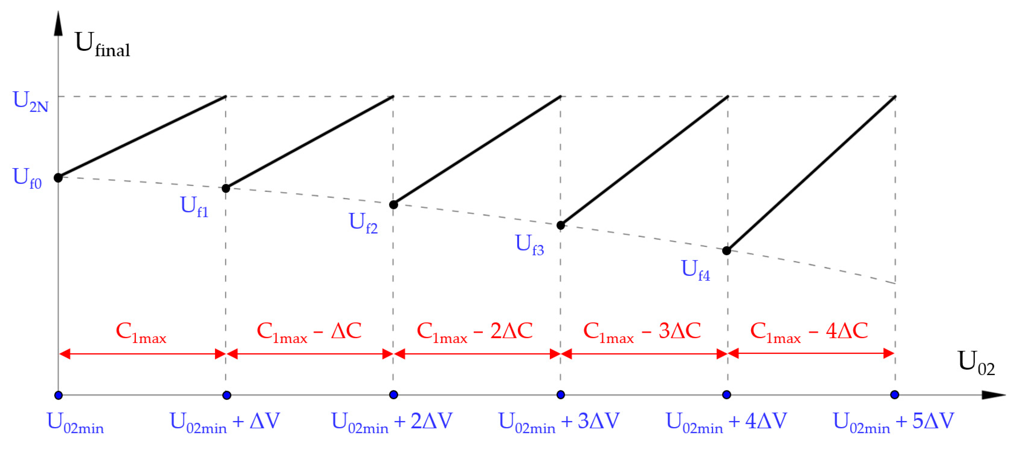
Considering that U01 is a low value, the capacitance of the charger will be considerably higher than that of the vehicle’s SC bank. It can be concluded from (24) that it will be necessary to modify the value of C1 according to the initial voltage of the vehicle’s accumulator, U02. This will be done by adding or removing modules of SCs in a discrete way (Figure 3).
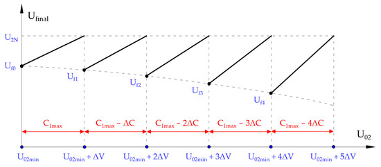
Figure 3.
Final voltage, Ufinal, for each initial voltage at the load, U02, as a function of the values taken by the capacitance C1.
As stated above, the minimum voltage of the SC bank will be 50% of its rated voltage, U02min = 0.5U2N. For U02min, a first value for the final voltage, Uf0, will be set. At that point, the capacitance of the charger will be the maximum, C1max. If the value of C1max remains constant and no SC module of the charger is disconnected, the higher the initial voltage of the vehicle’s accumulator, U02, the higher the final voltage of the assembly, Ufinal. When Ufinal = U2N, the initial voltage of the accumulator will present the value U02 = U02min + ΔV. As soon as this value is surpassed, a module of the charger’s SCs, with ΔC capacitance, will be removed, changing the capacitance of the charger to a new value, C1 = C1max − ΔC. For this new value of capacitance and with this new initial voltage in the vehicle’s accumulator, the final voltage of the set would be Uf1. For the new charger capacitance, C1 = C1max − ΔC, by increasing the value of U02, the final voltage would increase again so that for U02 = U02min + 2ΔV, the final voltage Ufinal = U2N would be reached again. This process is repeated iteratively. The final voltage can be expressed as a function of C1, C2, U01, and U02 as follows:
As can be reasoned from (25), the final voltage is a linear function, in which decreasing C1 decreases the ordinate at the origin and increases the slope of the line. If the first value of the final voltage, Uf0, is very close to the value U2N, ΔV will have a lower value and, therefore, more steps in the capacitance of the charger will be necessary. This situation implies a higher cost of the installation. However, the values of all final voltages (Uf0, Uf1, …, Ufn) will be closer to the rated value, U2N, so that the vehicle accumulator will always be closer to its rated voltage and will therefore have more energy stored for the next trip. If a low number of steps is chosen, the final voltage that the accumulator will reach will be somewhat further away from its rated value, but the system will present a lower cost. Which decision must be taken depends on what the designer wishes to prioritize, as both are valid. The first value of the final voltage, Uf0 (Figure 3), should be chosen so that the ratio C1max/ΔC is an integer. Constructively and industrially, it is easier to add or remove SC modules of the same capacitance. Identical modules are not only cheaper to manufacture, but their dimensions are also identical, and assembly is more practical and compact.
It can be shown that if it is true that
For the relationship in (26) to be fulfilled, the first value of the final voltage, Uf0, must be as follows:
where n being an integer number that defines the steps that the voltage, U02, will have from the value U02min to U2N. If U02min = 0.5U2N, the previous equation is transformed as follows:
The voltage increase, ΔV, used for the different steps, will be a function of the value of Uf0 calculated in (29) as follows:
The charging station control system is very simple. Before connecting the vehicle, it is only necessary to measure the voltage of its accumulator, U02, and, depending on this, then select the capacitance of the charger by adding or removing the necessary SC modules. Once the capacitance ΔC of the blocks that make up the charger, and therefore the C1 value, has been established, R1 can be obtained; the properties of the cells that form the banks of SCs are known.
It should be borne in mind that both C1 and R1, as well as C2 and R2, will change as the cells age. This will be analyzed when sizing the smoothing inductor so that the system will correctly operate throughout the lifetime of the charger and vehicle battery components. Figure 3 graphically shows the process described above.
2.2.2. Selection of the Properties of the Inductor: Inductance and Internal Resistance
Since the internal resistances of the two banks of SCs are known, the value of the internal resistance of the inductance, RL, can be directly calculated from (2).
From the definition of γ in (17), two curves, β(γ), can be obtained for each of the imposed conditions: maximum charging time, tcharge, and peak current, Imax. The first one is extracted from (13) and is designated by β1(γ) as follows:
The second function, β2(γ), is calculated from (16), as a function of the maximum admissible current. Considering how the parameter β has been defined, where according to expression (7) it is satisfied
the value of the inductance can be obtained as a function of γ and β from (31) as follows:
Substituting this value in (16) and considering the definition of γ, a second function, β2(γ), which depends on the peak current, will be obtained:
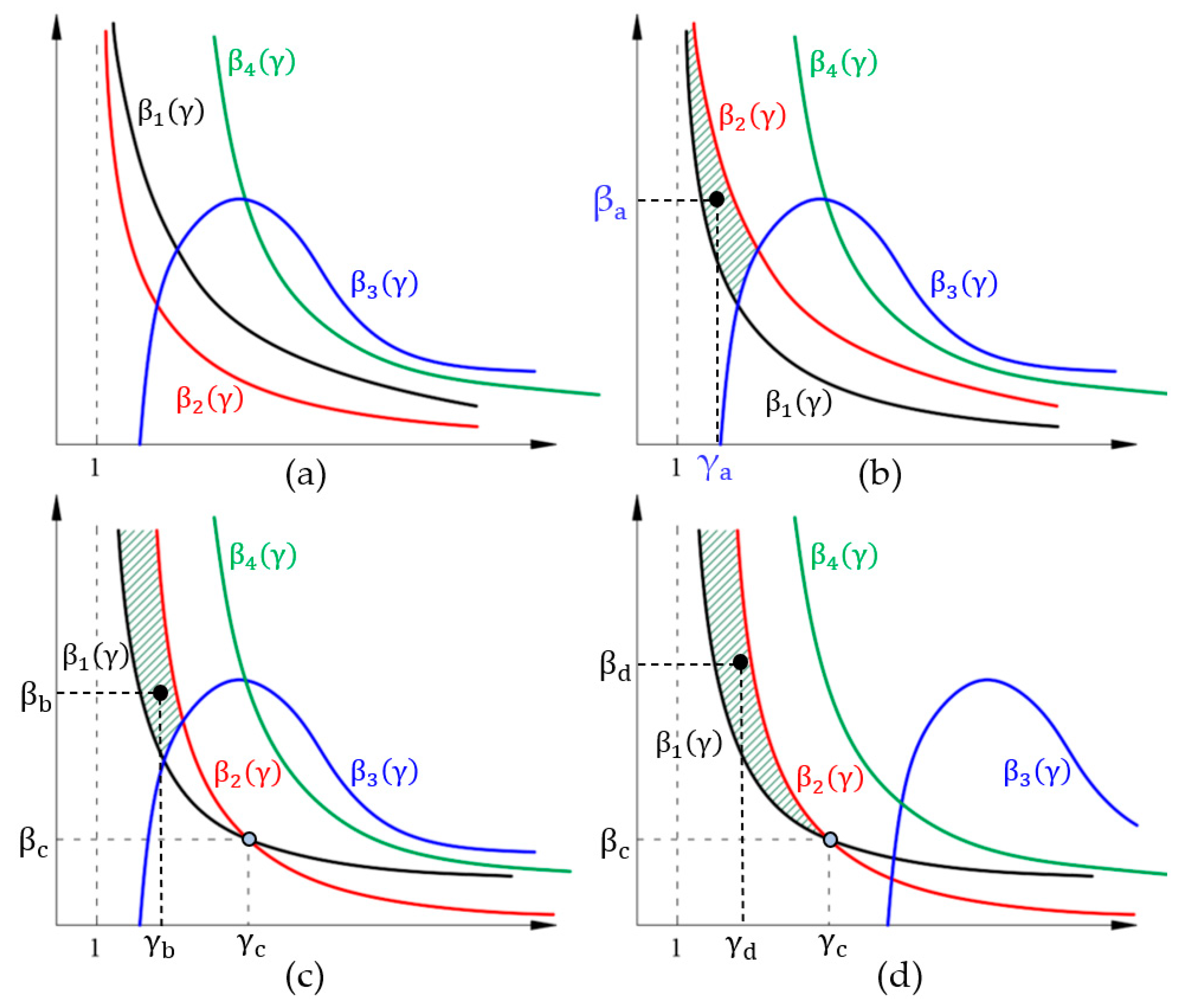
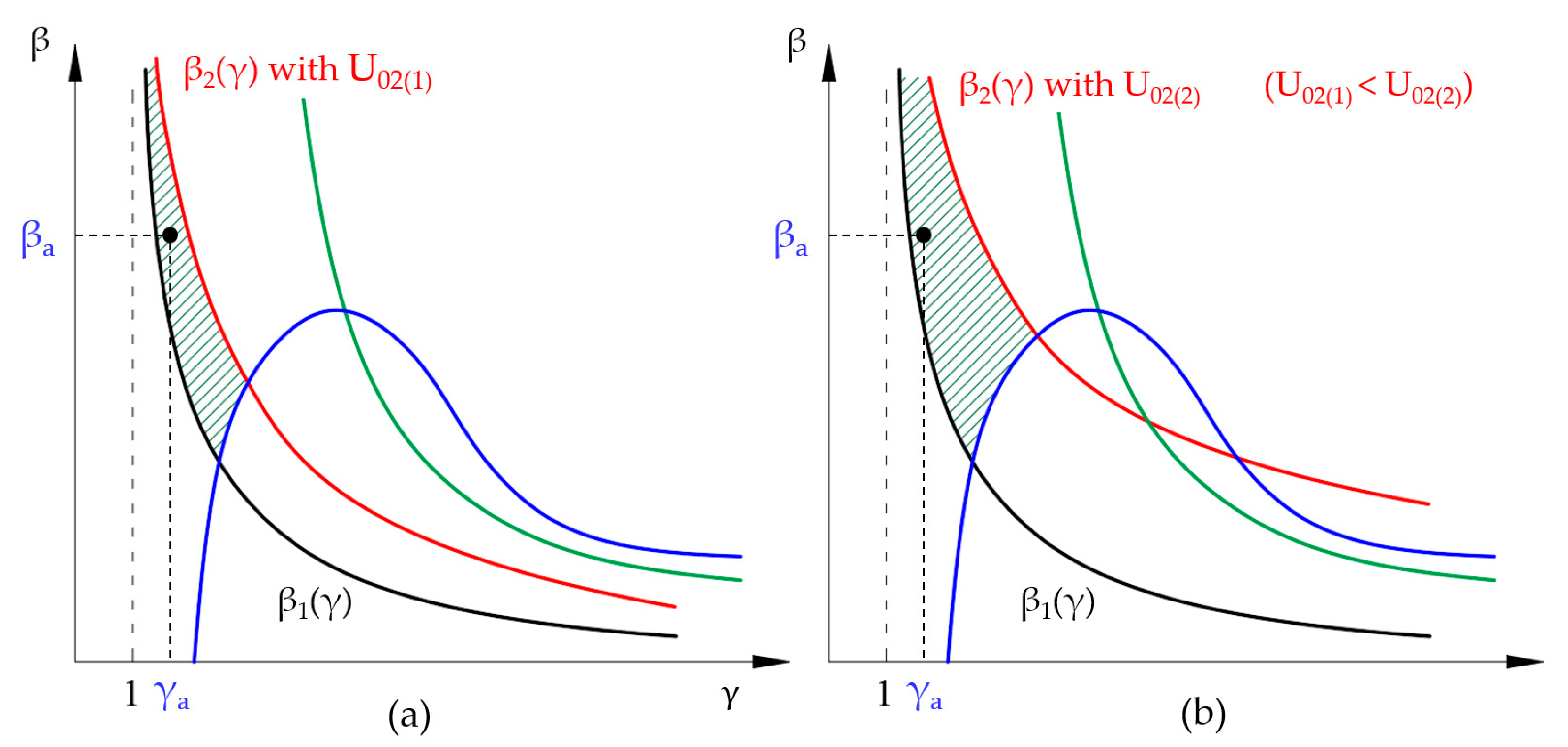
β1(γ) and β2(γ) are positive continuous and decreasing functions (Figure 4). They are defined for values of γ belonging to the open interval (1, ∞). Both have the particularity that if γ tends to 1, β tends to infinity and that if β tends to zero, γ tends to infinity. In order not to exceed the maximum charging time, tcharge, the pair (γ, β) must lie above the curve β1(γ). Similarly, for the maximum current value, Imax, not to be exceeded, any pair of values (γ, β) must be below the curve β2(γ). The solution must therefore be a pair of (γ, β) values that lies between the β1(γ) and β2(γ) curves, thus fulfilling both constraints.
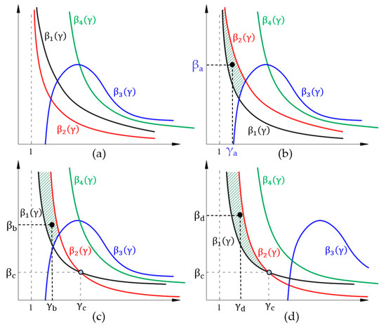
Figure 4.
Functions β1(γ), β2(γ), β3(γ) and β4(γ) represented for different cases; (a) case with no possible solution; (b–d), different cases where it is possible to find a solution (striped area).
By choosing a pair of values (γ, β), the value of the inductance, L, and the minimum resistance of the whole circuit, RTmin, can be obtained as follows:
Since the internal resistances of the charger’s SC bank and the vehicle’s accumulator, R1 and R2, are known, the value of the internal resistance of the smoothing inductor, RL, will be directly calculated. As the charging station is going to handle very high currents, the most suitable option is to use air-core inductors with large cross-section conductors.
In addition to the above restrictions for γ and β, it is necessary to add two further conditions: the values of L and RT must be calculated for the lowest value of the voltage in the vehicle’s accumulator, U02min, which corresponds to the maximum equivalent capacitance, Ceq_max, and the minimum equivalent resistance, RTmin.
However, if the vehicle arrives at the charging station with a voltage higher than U02min + ΔV, it will be necessary to disconnect SC modules of capacitance ΔC, which will decrease the value of Ceq and increase the value of the total resistance. If for a given capacity Ceq_max a point (γ, β) with a very low initial beta value is selected, it is possible that, as the charger capacity, C1, is reduced, which leads to a decrease in Ceq, β decreases so much so that the system becomes underdamped. As stated above, this type of transient regime is not admissible due to the oscillations that can appear in the voltages of both banks of SCs, which could exceed their maximum admissible voltage. The value of β must be such that, with the minimum equivalent capacity (when the maximum number of ΔC modules have been disconnected), the system never goes into an underdamped regime. This condition shall be satisfied if β > 0 whatever the value Ceq and RT, which is the same as imposing that the following inequality is satisfied
In the calculation of RTmax and Ceq_min, it is necessary to consider the change that aging causes in the properties of the charger’s and vehicle accumulator’s SCs. Data provided by the manufacturers indicate that at the end of their lifetime, the internal resistance doubles and the capacitance is reduced by 20%. If the system is to be operated for any level of cell aging both in the vehicle and in the charger, the maximum of total resistance, RTmax, and the lowest value of the equivalent capacitance, Ceq_min, must be considered in (36). These two values can be calculated from the initially chosen pair (γ, β) (at the beginning of the lifetime and with minimum U02). Since at this point C1min, R1max (charger capacitance and resistance at the beginning of the lifetime with all capacitance steps ΔC disconnected), C2, and R2 (vehicle accumulator capacitance and resistance at the beginning of their lifetime) are known, and considering that the charger and the vehicle cells are equally aged, that is, at the end of their lifetime, their resistances double and their capacitances decrease by 20%; therefore, the values of RTmax and Ceq_min can be calculated as follows:
By defining ΔRmax as the largest increase that the total resistance of the circuit will suffer, considering both the minimum capacity of the charger and the maximum aging in the SC banks of the charger and vehicle, through the substitution of the values of RTmax and Ceq_min given in (37) and (38), respectively, into (36), the following curve β3(γ) is obtained:
β3(γ) cuts the abscissa axis at the point where γ takes the following value:
Any pair (γ, β) which is a valid solution, chosen at the beginning of the lifetime of the cells, and which is above the curve β3(γ) will ensure that, with the minimum system capacity and maximum resistance, the transient period stays overdamped. There remains, finally, one last constraint: when the value of the minimum circuit resistance, RTmin, is calculated in (35), the result cannot be less than the sum of minimum resistance of the charger and the minimum resistance of vehicle’s accumulator, both calculated at the beginning of their useful life. Therefore, the following must be satisfied:
If inequality (41) is not fulfilled, the resistance RL would be negative. If the equality were satisfied, the limit and ideal case would be reached, where RL would have a practically negligible value. Considering this extreme situation, a fourth curve, β4(γ), can be calculated:
The pair (γ, β) that is a valid solution will be the one above the curves β1(γ) and β3(γ) and below β2(γ) and β4(γ). There will therefore be infinite solutions placed in a given area of the γ–β plane. Once the four functions have been graphically represented, it is easy to find out where they are located. In the following, some of the different cases that appear in the search for the solution will be explained and graphically presented. The first situation is the one shown in Figure 4a, in which the β1(γ) curve is above the β2(γ) curve. In this case, the only solution is to change the operating limits of the charging station by allowing a longer charging time, a higher current limit, or both. In the second case (Figure 4b), there is a zone (striped area) where it is possible to find a pair (γ, β) that lies between the curves β1(γ) and β2(γ) and also lies above β3(γ) and below β4(γ). A possible solution would be the point (γa, βa). In Figure 4c the situation is similar to the previous one; in this case, although the curves β1(γ) and β2(γ) intersect at the point of coordinates (γc, βc), this situation does not differ from the previous one, since the limitation of the valid area will be set by the curve β3(γ). However, in Figure 4d the cut-off point (γc, βc) appears to the left of β3(γ), so the admissible area will be the one limited by the cut-off point of the functions β1(γ) and β2(γ).
Figure 4 has shown only some of the situations that could arise to explain how to locate the area where a pair (γ, β) can be found such that it can be a valid solution, although there may be more combinations depending on the values set for maximum current, maximum charging time, etc.
In the examples in Figure 4c,d, to calculate the cut-off point between β1(γ) and β2(γ), point (γc, βc), it is only necessary to equal both functions. The resulting equation is as follows:
By solving (43), γc is calculated as follows:
with W−1(x) being the secondary branch of Lambert W function. For the sake of simplicity, a dimensionless variable, k, has been used in (44):
If γc is replaced in (30), βc can be expressed as follows:
β1(γ), β3(γ), and β4(γ) do not depend on the initial voltage of the vehicle’s accumulator, U02, nor on the equivalent capacity, thus they will always be in the same position. However, the curve β2(γ) does depend on U02 which will move in the range 0.5U2N ≤ U02 ≤ 0.8U2N. If in (33) it is considered that ΔU = U01 − U02 and Ceq is calculated by means of the relationship between C1 and C2 in (24), assuming that for any value of U02, Ufinal will suffer negligible changes, and the β2(γ) curve can be expressed as follows:
According to (47), as U02 increases, considering that C2 only varies as it ages and does so by decreasing its value, the curve β2(γ) will shift upwards, which causes the area between β1(γ) and β2(γ) to widen. The most restrictive situation to find a valid situation, therefore, corresponds to U02min, which implies the use of the maximum capacity of the charger, C1max, and its minimum internal resistance, R1min. Obviously, the equivalent capacity, Ceq_max, will also be the maximum and the total resistance, RTmin, the minimum. Figure 5 shows how the function β2(γ) varies as the initial voltage at the load, U02, increases:
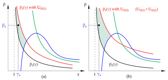
Figure 5.
Functions β1(γ) and β2(γ) for different initial voltages of the vehicle accumulator, U02(i). (a) Voltage U02(1) with a low value, (b) Voltage U02(2) with a higher value.
3. Discussion
In this section, a practical case of the design of a fast-charging station will be presented. The starting point will be the electric bus Tecnobus Gulliver U500™, whose hybrid storage system consists of 72 V and 120 Ah lead-acid batteries and three Maxwell Technologies™ 125 V and 63 F SC modules connected in series. The bus has been designed to be used with a fast-charging system for the SCs and uses a pantograph manufactured by Schunk™. All the features of both the bus and the charging system can be found in [20]. The charging station proposed here is different from that of the manufacturer.
Two strategies for charging SCs are analyzed in [20]: The first one consists of using a single stage where the charging time is 24 s, and the maximum current is 1152 A. The second presents three stages; in each of them the current does not exceed 513 A, but the charging time is extended to 40 s. For the fast-charging station proposed in this paper, the system will be sized to complete the charging in a maximum time of 30 s, in the worst case, and with a maximum peak current of 1 kA. Both the charger and vehicle cells can endure up to 1.9 kA; however, the design current limit shall be set at 1 kA. With this limit, the charging process shall be correctly performed for different initial voltages in the vehicle accumulator, as well as for any degree of cell aging.
Each SC module on the bus consists of 48 cells with a rated voltage of 2.7 V. Since the three modules are series connected, the whole accumulator will present a rated voltage (U2N) of 375 V. Following the manufacturers’ recommendation to limit the maximum discharge to 50% of its rated voltage, the vehicle’s accumulator will discharge up to 187.5 V at most. As for the charger, an initial voltage, U01, of 400 V will be set in order to optimize energy transference and prevent the cells from reaching too high of a voltage. In addition, to ensure that the final voltage of the SCs is, in all cases, close to U2N, the number of U02 steps, n, will be set to 8. These data are shown in Table 1. The array of SCs installed in the bus presents the rated values shown in Table 2.

Table 1.
Initial values of the variables to start the design of the charger.

Table 2.
Data of the vehicle accumulator’s SCs.
First, the final voltage, Uf0, will be calculated so that the set of capacitors forming the charger will consist of seven identical modules. According to (28), the voltage will be 371.9 V, which will be used when the vehicle arrives with the minimum voltage, 187.5 V. According to (24), the maximum capacitance of the charger will be 137.8125 F. The value of ΔV in this case, according to (29), will be 23.4375 V. The modules of capacitance ΔC that will form the charger, according to (26), will be of 19.6875 F (there will be 7 identical units). If it is considered that the bus will never arrive at the charging station with a voltage higher than 80% of U2N (300V), in the case where n = 8, the charger can be designed such that U02max = 304.7 V (a very close value to 300 V). There will then be five steps for the voltage U02 and four steps for the capacitance of the charger so that only four modules of SCs with capacitance ΔC will be connected by means of contactors, and three other blocks of the same capacity connected in parallel will not need any kind of switch.
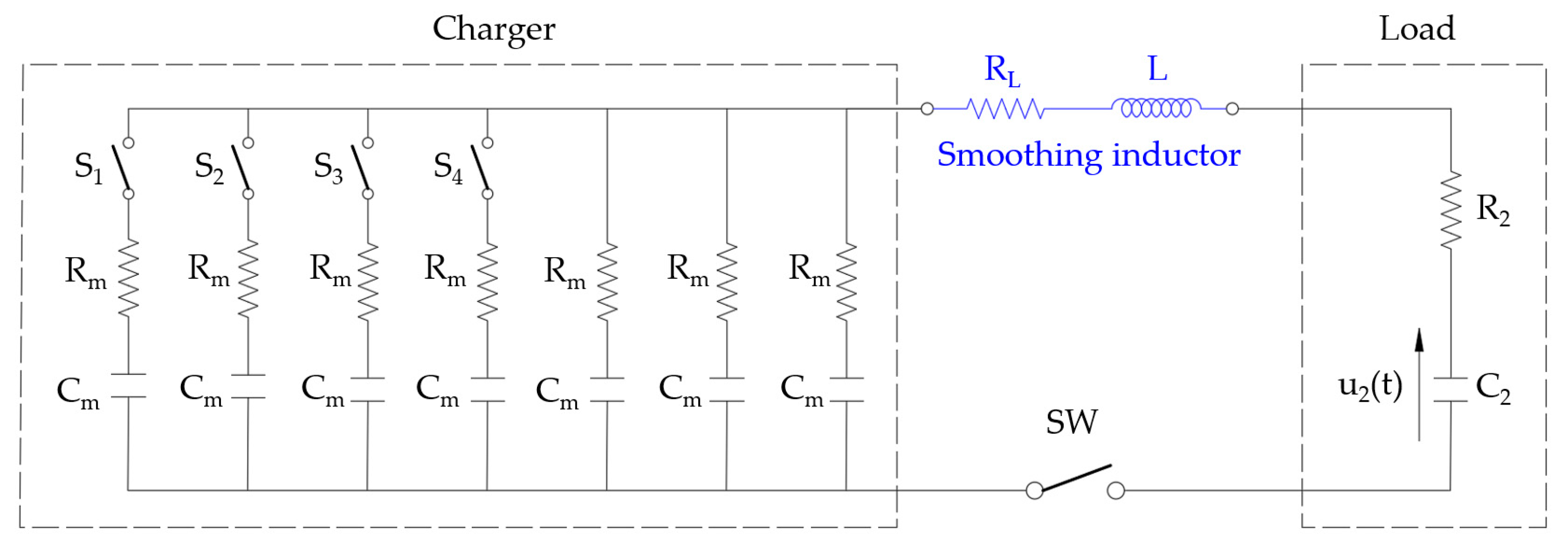
For the actual construction of the charger, commercial products should obviously be used, and, with them, it will be necessary to achieve values as close as possible to those calculated. As a practical example, cells from Maxwell Technologies™, one of the best-known manufacturers, have been selected. By connecting 152 cells of 3000 F and 0.15 mΩ with a rated voltage of 2.7 V in series, modules with a capacitance Cm = ΔC = 19.737 F and an equivalent resistance Rm = 22.8 mΩ will be obtained. The maximum voltage the modules could withstand is 410.4 V, although in the design, the maximum voltage will be set at 400 V in order to improve efficiency. Figure 6 shows a wiring diagram of the charging station connected to the vehicle’s accumulator.
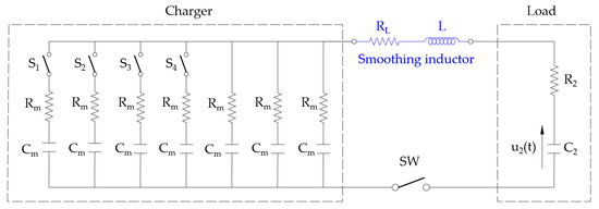
Figure 6.
Wiring diagram of the fast-charging station connected to the vehicle accumulator.
Depending on the number of modules being used by the charger, connected via contactors Si (i = 1, 2, 3, 4), the equivalent resistance and capacitance values, R1 and C1, will be those in Table 3.

Table 3.
Resistance and capacitance of the charger, R1 and C1, and equivalent capacity, Ceq, at the beginning of the lifetime, depending on the number modules.
The final voltage that the assembly will reach, Ufinal, can be defined in sections, corresponding to the variation of C1. Each of them will be a straight line, expressed in the form; Ufinal = a + b·U02, where both the ordinate at the origin, a, and the slope, b, will change, as shown in (25). With the values of the case study, the results are presented in Table 4.

Table 4.
Final voltage, Ufinal, as a function of the initial voltage of the vehicle, U02, and the capacitance of the charger, C1.
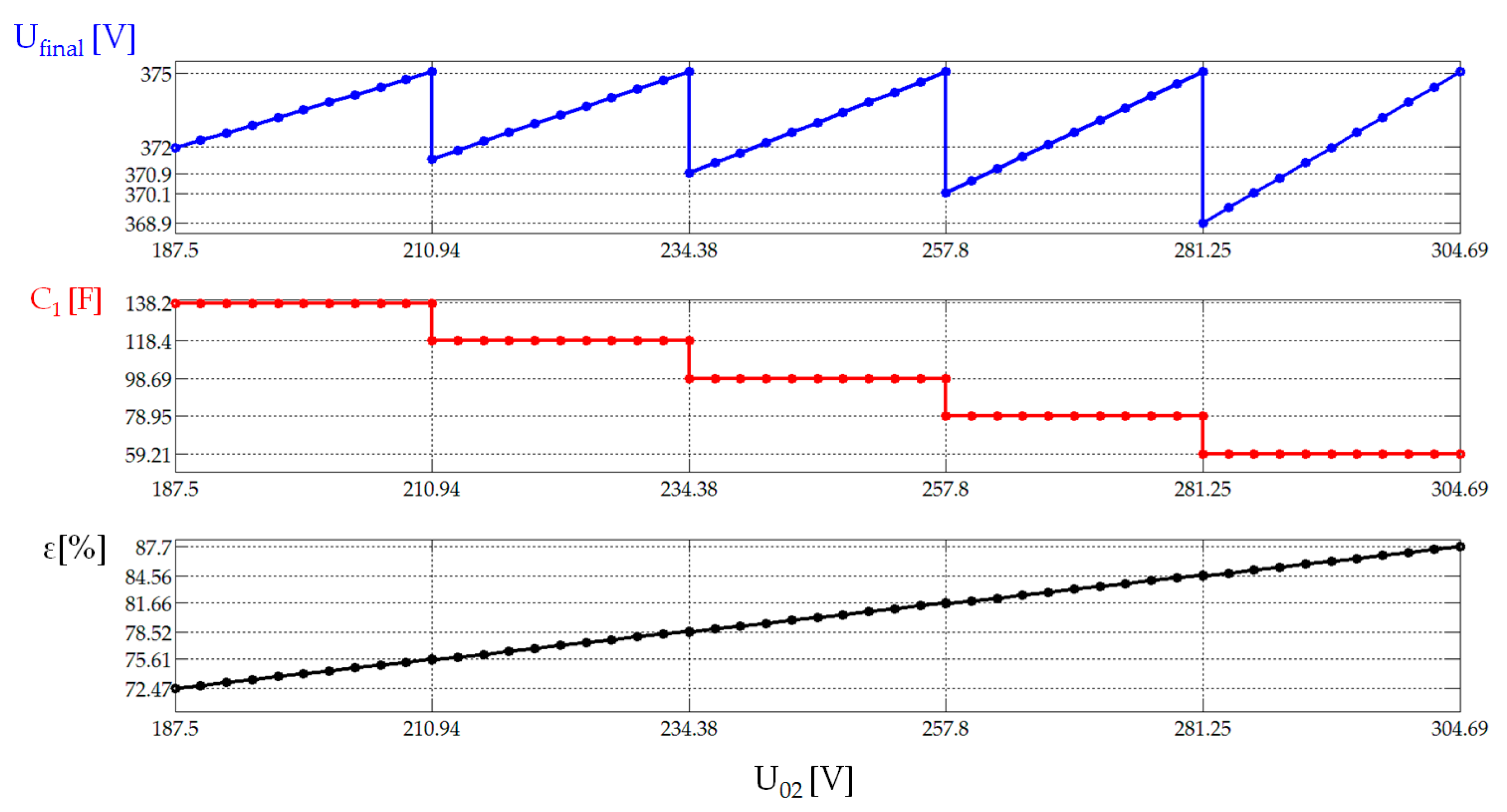
Figure 7 shows the values that the final voltage, Ufinal [V], the capacity of the charger, C1 [F] (at the beginning of its useful life), and the efficiency of the charging process, ε (%), will take as a function of the different values of the vehicle accumulator’s initial voltage, U02 [V]. The efficiency presents values between 72.47% and 87.7%, assuming that the initial voltage of the load, U02, is in the range [187.5, 304.69].
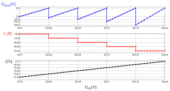
Figure 7.
Value of the voltage, Ufinal [V] (above), capacity of the charger, C1 [F] (middle), and efficiency, ε [%] (below), as a function of the values that the voltage will take at the load, U02 [V].
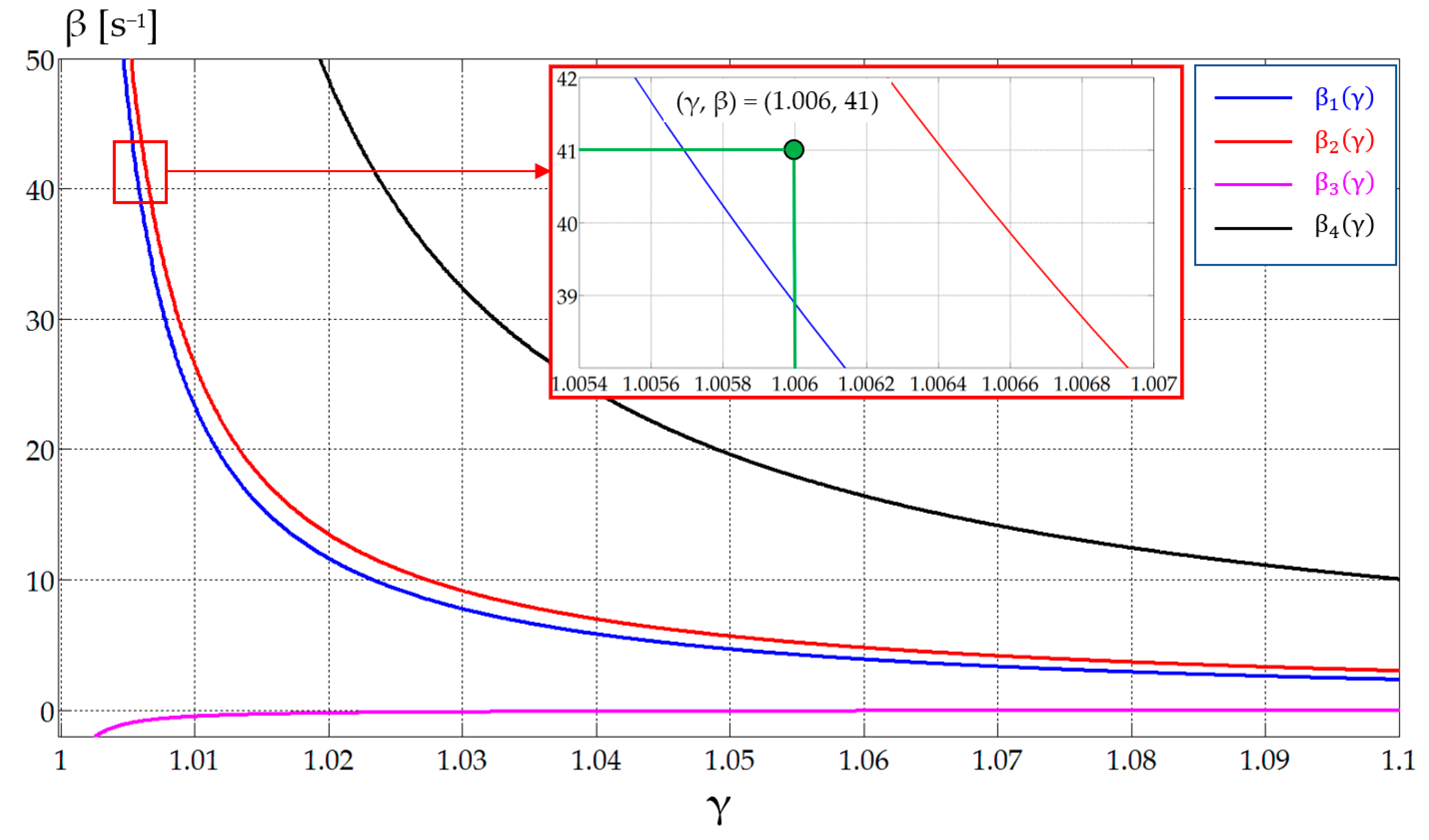
Once the charger design has been completed, it is necessary to calculate the values of the inductance and the internal resistance of the smoothing inductor. Figure 8 shows the four curves, β1(γ), β2(γ), β3(γ), and β4(γ), for the worst case (U02min = 187.5 V). In this case, it would be sufficient to choose a combination (γ, β) that lies between the curves β1(γ) and β2(γ), since it will always be below β4(γ) and above β3(γ). One of the infinite possible combinations has also been pointed out, where the pair of values γ = 1.006 and β = 41 has been taken as a valid solution. A high value for β has been chosen so that a low value of inductance is obtained to make it possible to find a commercial product.
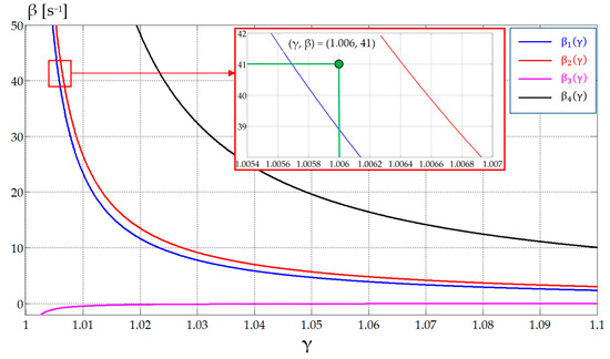
Figure 8.
Graphical representation of the functions β1(γ), β2(γ), β3(γ), and β4(γ) and the pair (γ, β) = (1.006, 41) chosen to obtain the required inductance.
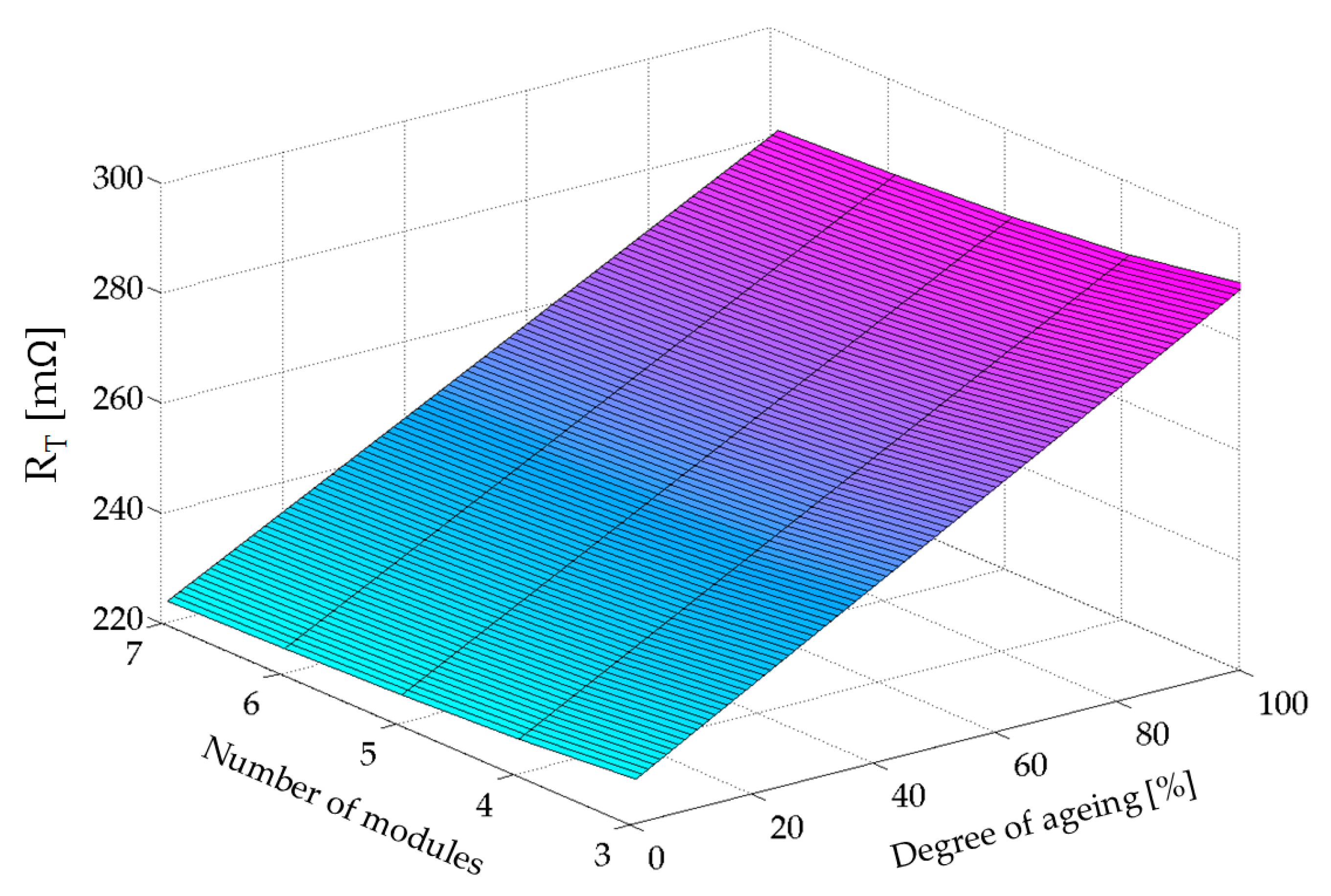
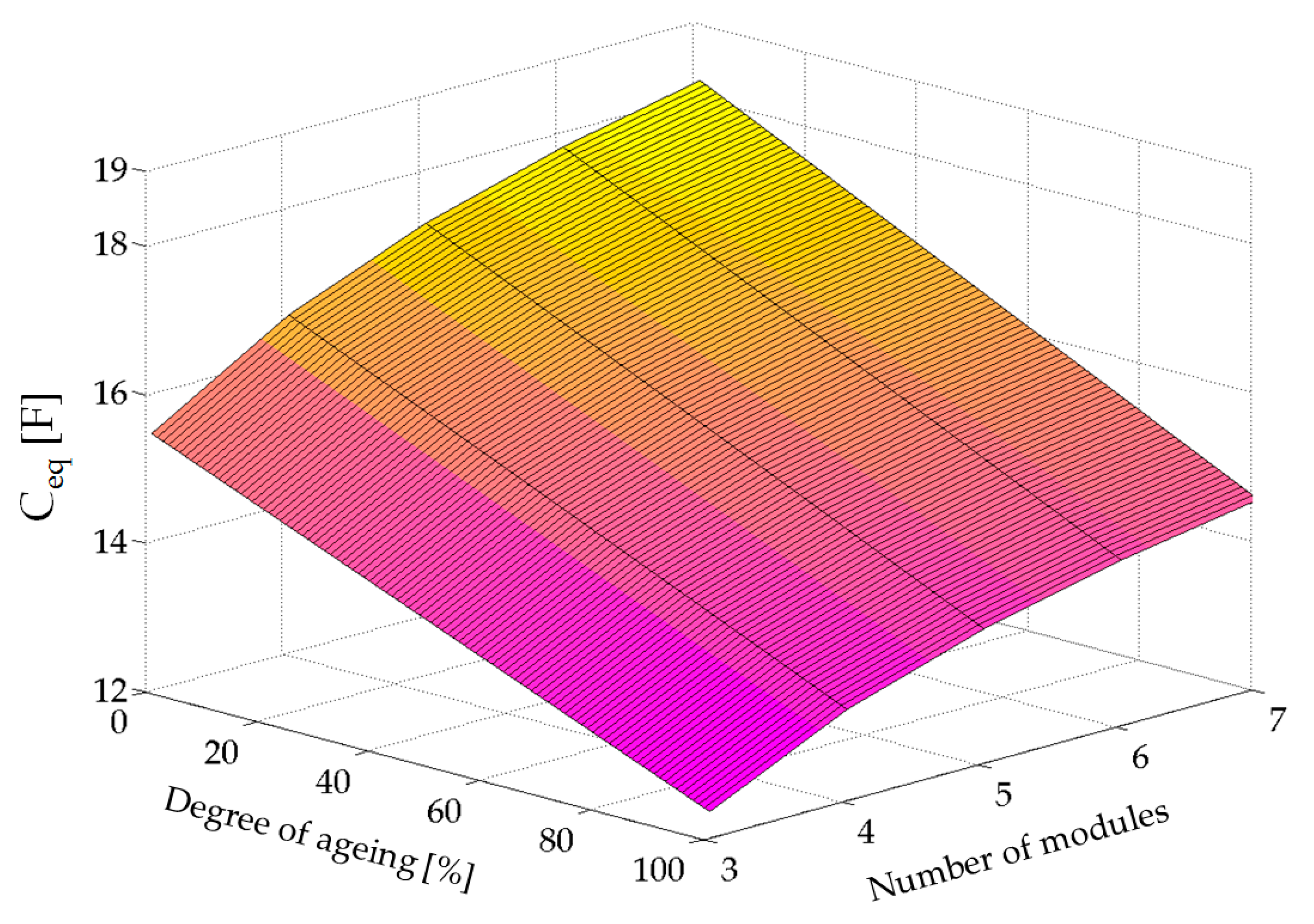
By taking the solution between the functions β1(γ) and β2(γ), the peak current will never reach 1 kA, and the charging time will always be less than 30 s. Considering that in this case Ceq_max = 18.229 F (see Table 3), the values of the inductance, L, and the minimum total resistance, RTmin, according to expressions (34) and (35), will be L = 2.71 mH and RTmin = 223.66 mΩ. Since in this case R1min = 3.26 mΩ and R2 = 54 mΩ, the inductance would have an internal resistance RL = 166.4 mΩ. These values can be achieved by using two inductances parallelly connected, identical to those as used in [20], which withstand 500 A of peak current. The equivalent resistance of this combination would be 77.5 mΩ, so a series resistor of 88.9 mΩ could be added to complete the 166.4 mΩ required resistance. The fast-charging station would therefore be completed using commercially available elements. Figure 9 shows the total resistance values of the charging station, RT [mΩ], as a function of the number of modules connected to the charger and for different cell aging. It has been considered that, at the end of the lifetime of the cells, the internal resistance of the charger and the vehicle accumulator will double. In the case of the smoothing inductor, no variation in its internal resistance over time has been considered. Figure 10 shows the variation of the equivalent capacitance of assembly, Ceq [F]. It has been considered that at the end of the lifetime of the cells, their capacitance will be reduced by 20% of their initial value. In this case, an aging of 20% means that the cells have lost 4% of their capacitance. The same value is considered for both the vehicle accumulator and the charger cells.
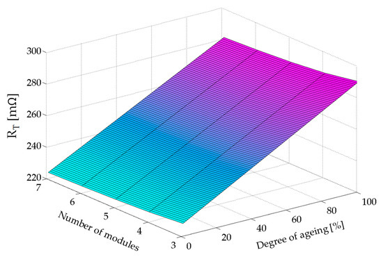
Figure 9.
Resistance of the assembly, RT [mΩ], for different number of modules and different degrees of aging of the cells.
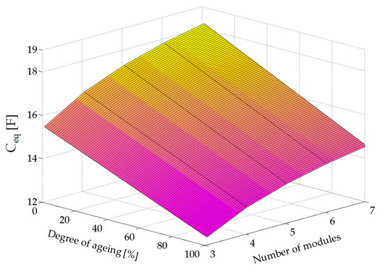
Figure 10.
Capacitance of the assembly, Ceq [F], for different number of modules and different degrees of aging of the cells.
The study will then be completed by simulating and plotting the results, and the validity of the design will be demonstrated in all cases including the aging of the cells in both the charger and the vehicle´s accumulator.
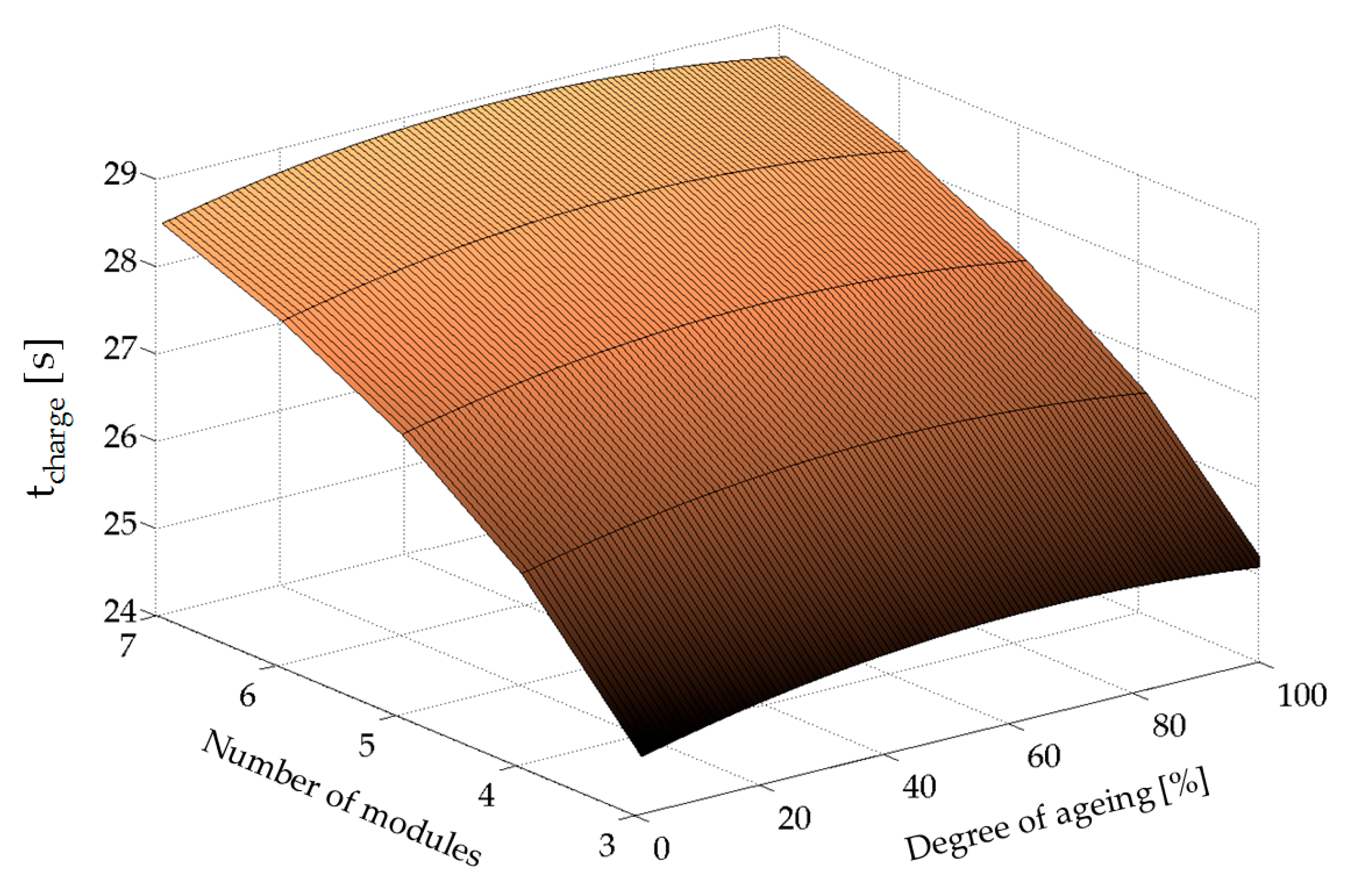
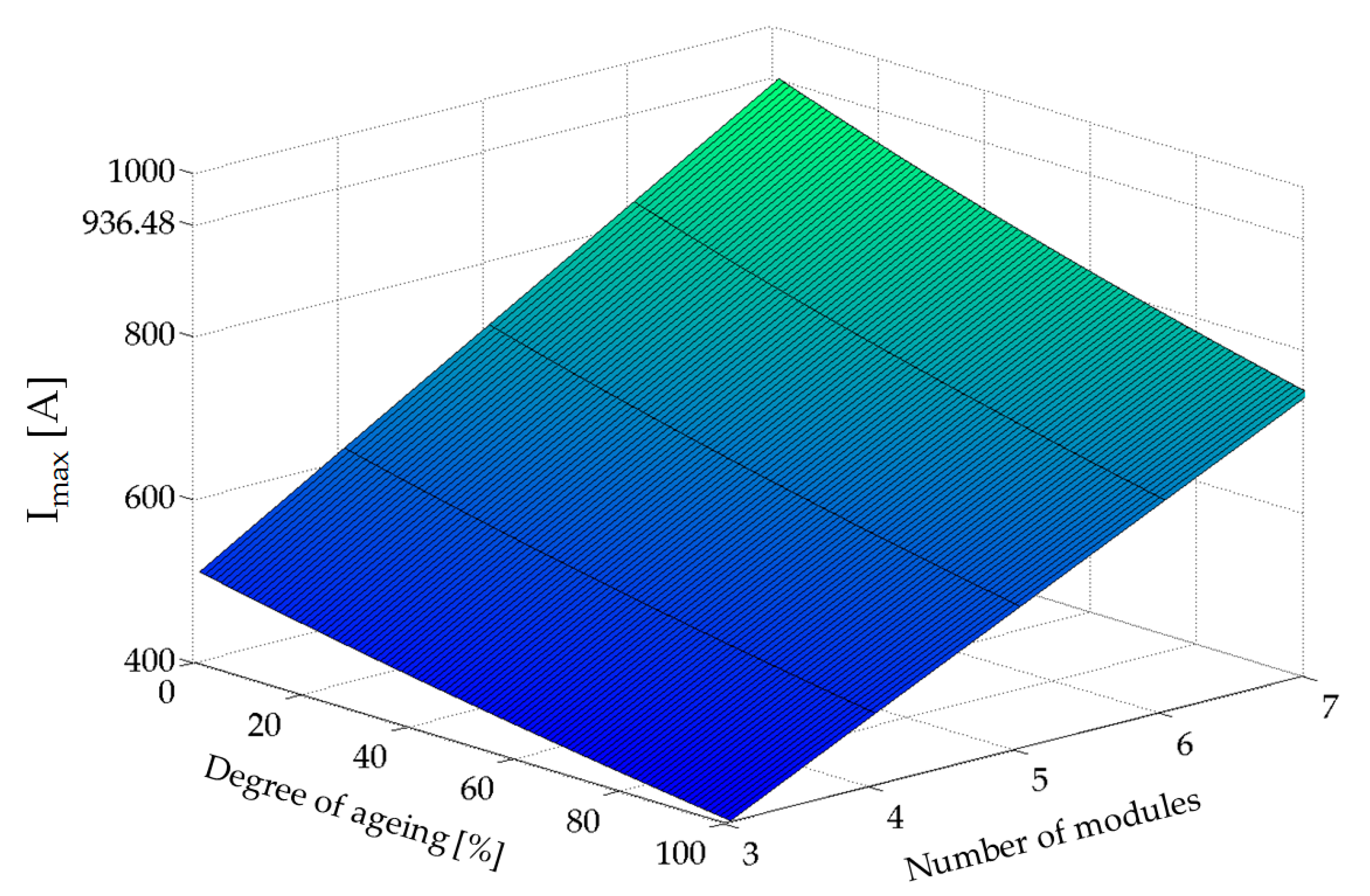
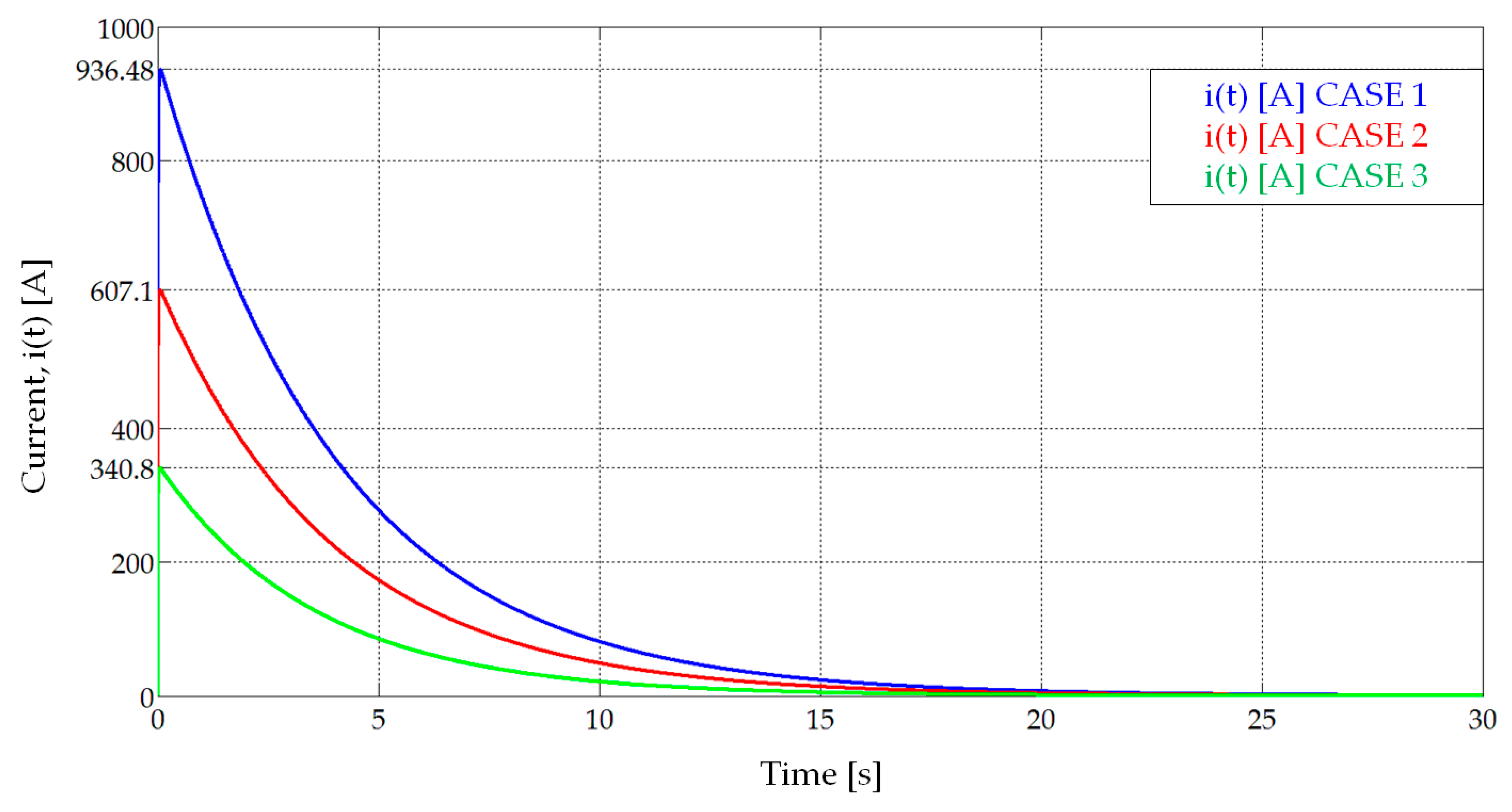
From the values that both the total resistance and the capacitance of the assembly will take as a consequence of its aging, the charging times can be calculated by means of (12). The results are shown in Figure 11, where it can be seen that in no case are the 30 s of charging time, set in the design, exceeded. Figure 12 presents the values of the maximum current, using (3), (5), (7) and (16) and also considering the aging process. The maximum value will appear at the beginning of the lifetime of the cells and at the minimum voltage of the vehicle accumulator (187.5 V). In this case, the peak current will be 936.48 A, meeting again the selected limit of 1 kA. For higher voltages in the accumulator and higher degree of aging of all cells, the peak current will decrease.
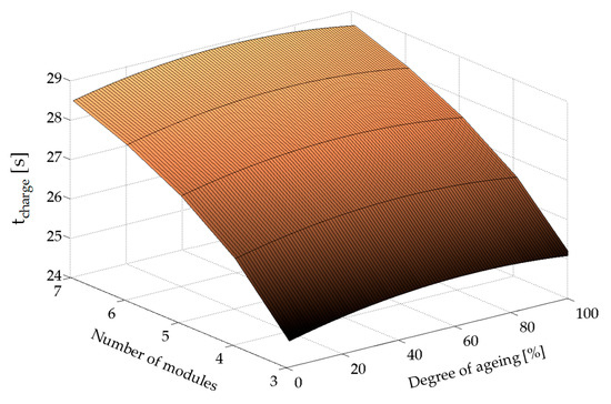
Figure 11.
Charging time, tcharge [s], for different number of modules and different degrees of aging of the cells.
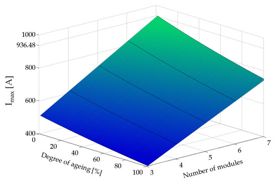
Figure 12.
Peak current, Imax [A], for different number of modules and different degrees of aging of the cells.
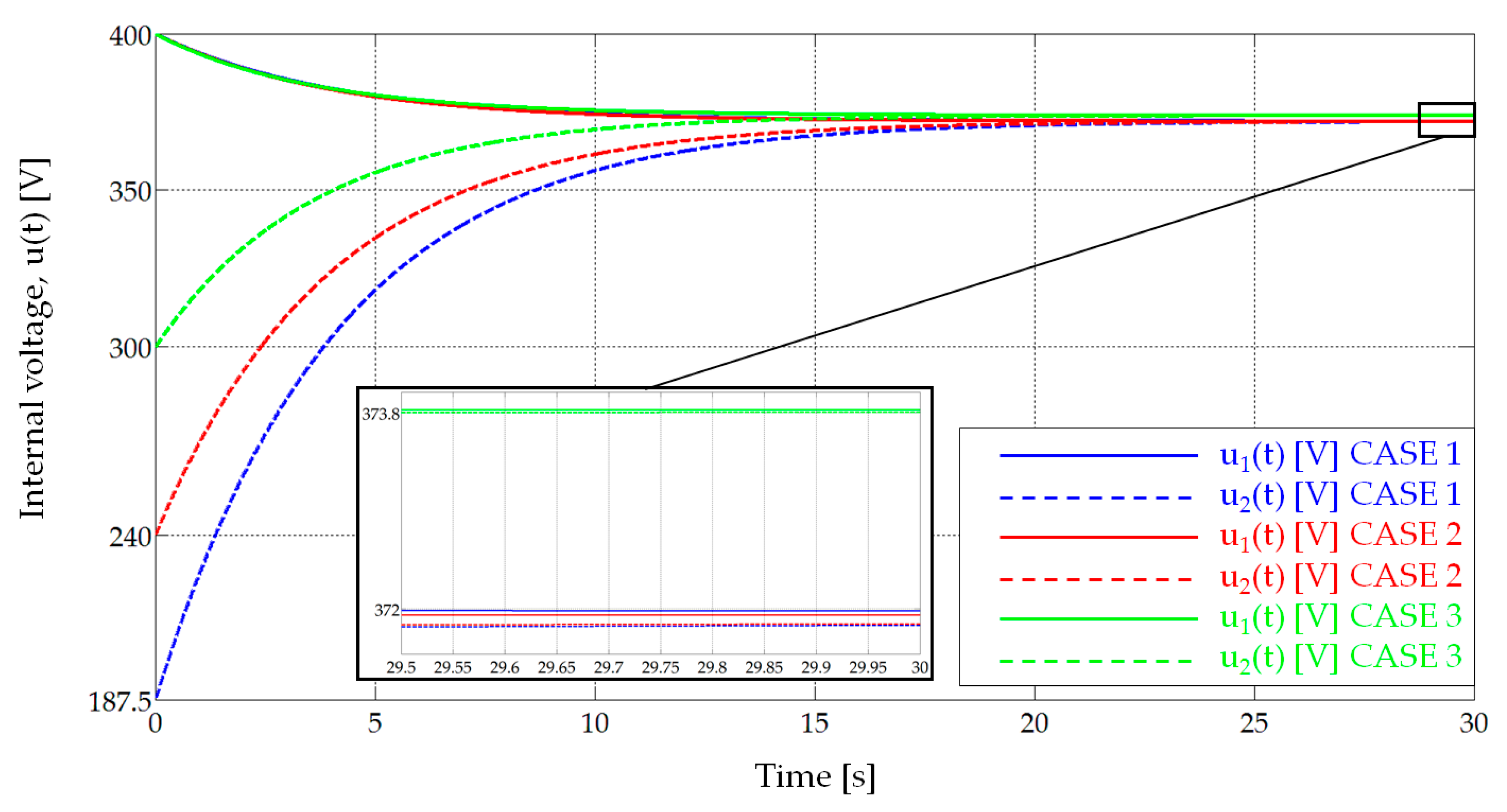
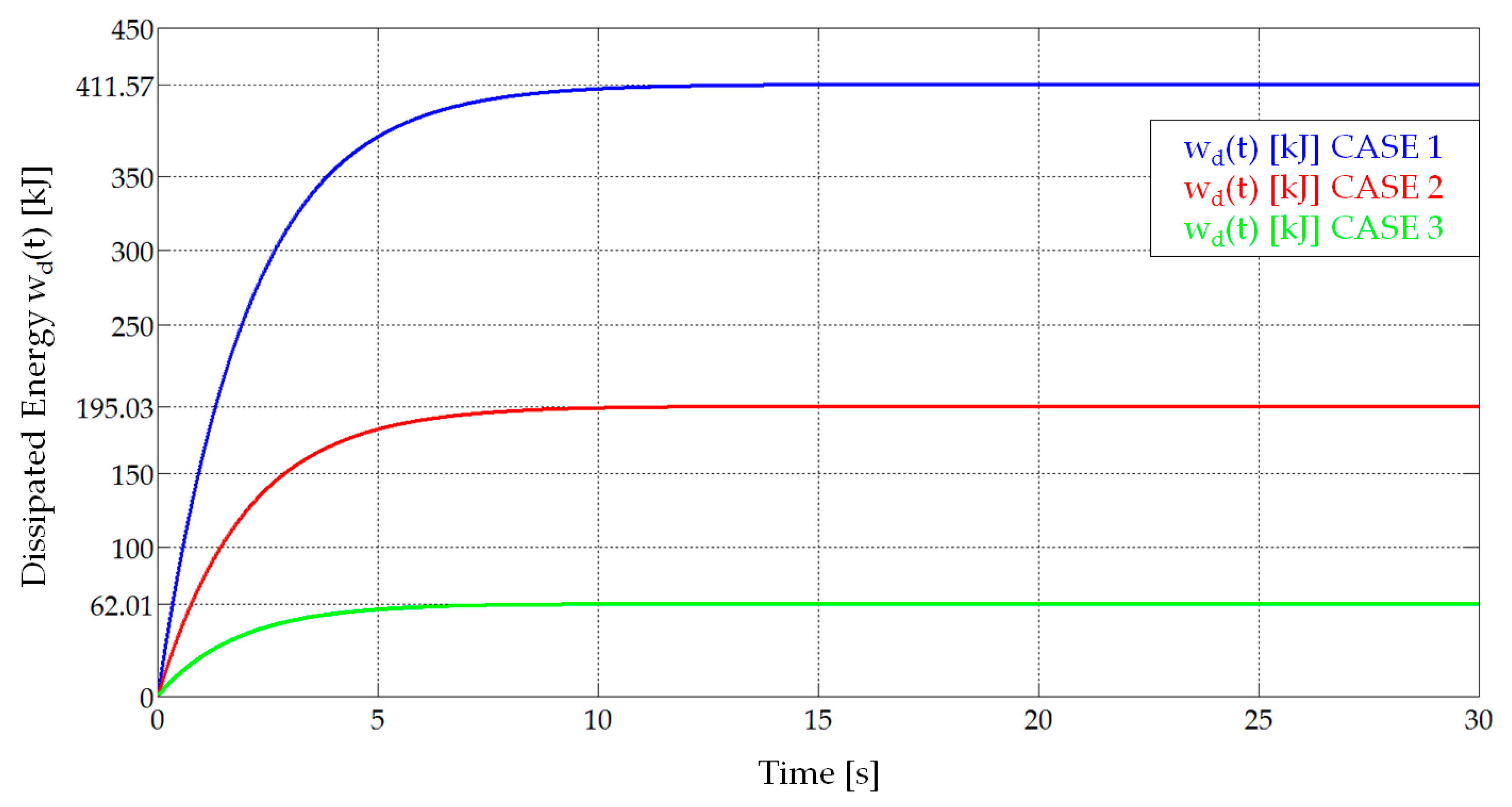
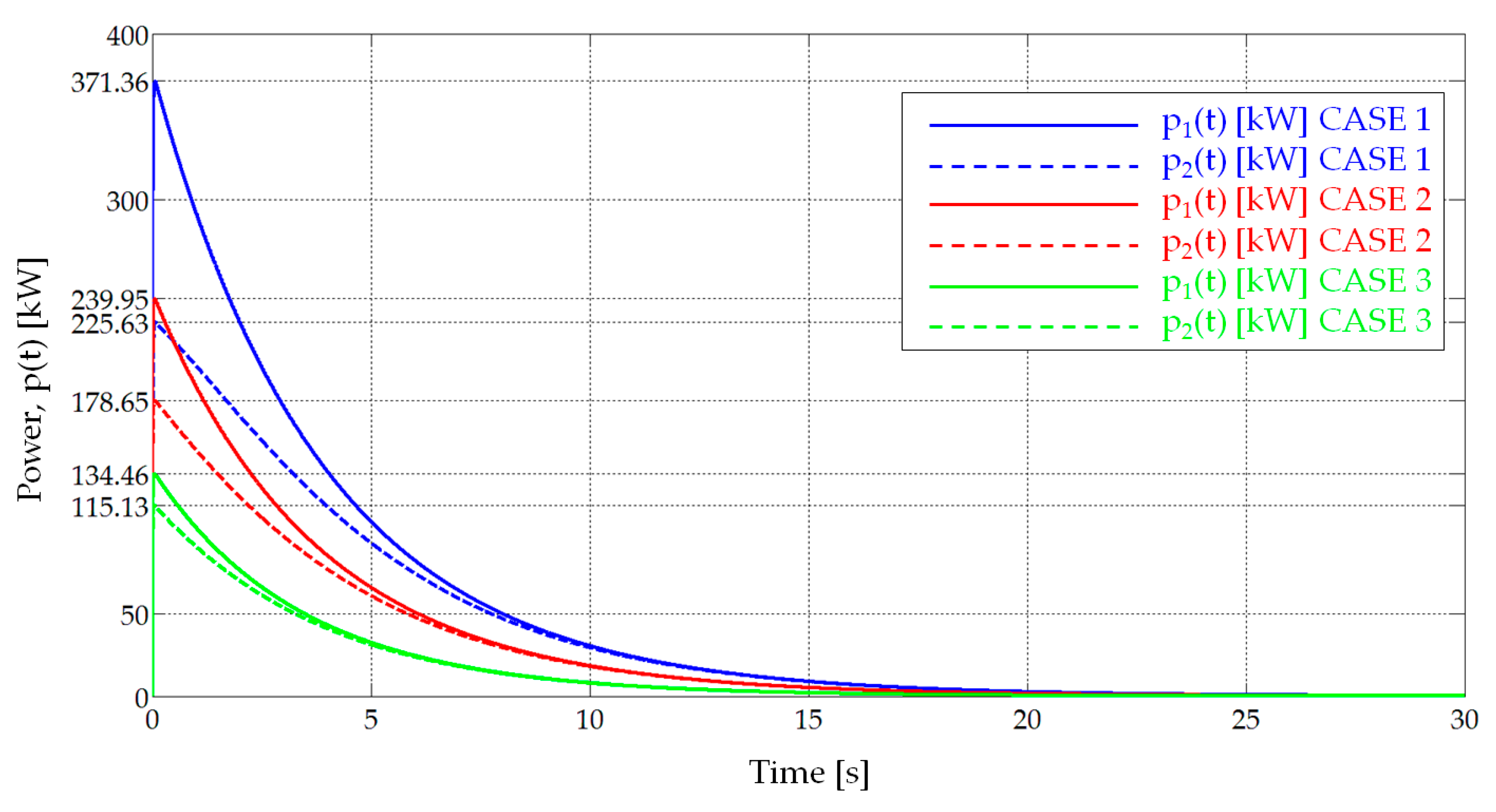
In the following, the results of three simulations will be presented where three cases are considered: (1) beginning of the cells’ useful life with seven capacitance steps ΔC (U02 = 187.5 V); (2) cells aged a 60% and five capacitance steps ΔC (U02 = 240 V); and (3) cells aged to a 100% and maximum voltage at the vehicle’s accumulator (U02 = 300 V). In all of them, it is considered that U01 = 400 V. The most extreme operating points have thus been chosen: minimum total resistance and maximum capacity, maximum total resistance and minimum capacity, and an intermediate case. Table 5 shows the data used in each of the three studied cases. Table 6 shows the most significant results of the three cases: the charging time, tcharge [s]; the maximum current, Imax [A]; the peak power generated by the charger, P1max [kW]; the maximum power absorbed by the vehicle, P2max [kW]; the energy dissipated in the whole process, Wd_total, expressed in kJ and Wh; and the efficiency of the charging process, ε [%].

Table 5.
Values of resistance, capacitance, initial load voltage, U02 [V], and final voltage, Ufinal [V], in the three simulated cases.

Table 6.
Main values in the three simulated cases.
Figure 13 shows the evolution of the current, i(t), in the three cases. Figure 14 presents the time evolution of the internal voltages in the charger, u1(t) [V], and the vehicle’s accumulator, u2(t) [V]. Figure 15 shows the value of the dissipated energy, wd(t) [kJ] as a function of time. Finally, Figure 16 is a graph of the value of the instantaneous power delivered by the charger, p1(t) [kW], and the power consumed by the vehicle’s accumulator, p2(t) [kW]. The highest instantaneous power that can be observed in the graphs will be the one corresponding to the first case when the cells are new, and the vehicle accumulator presents the minimum voltage. In this case, its value is 371.36 kW.
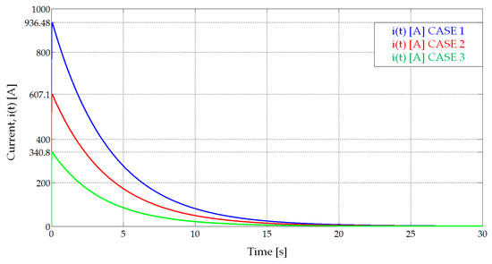
Figure 13.
Instantaneous current, i(t) [A], in the three studied cases (Table 5).
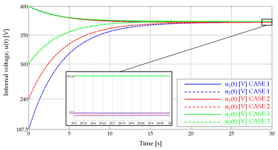
Figure 14.
Internal voltage of the charger, u1(t) [V], and the vehicle, u2(t) [V] (Table 5).
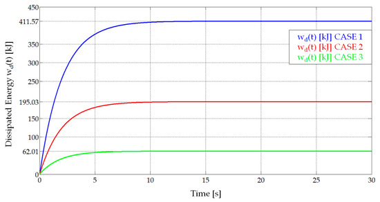
Figure 15.
Energy dissipated in the whole system, RT, wd(t) [kJ] (Table 5).
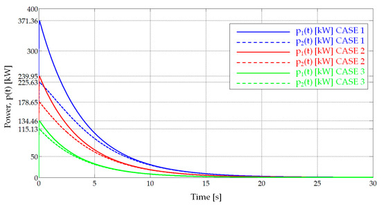
Figure 16.
Instantaneous power delivered by the charger, p1(t) [kW], and absorbed by the vehicle, p2(t) [kW], in the three studied cases (Table 5).
4. Conclusions
When electric vehicles integrate banks of SCs as energy storage systems, fast chargers that also use SCs present numerous advantages over other technologies. The most important, undoubtedly, is the ability to charge very quickly and handling very high power without causing distortions in the grid and without the need to use high-power converters.
In this paper, a methodology for sizing this type of fast charger has been presented. To this end, the mathematical formulation of the electrical variables involved in the vehicle charging process has been developed: instantaneous circuit current, SC voltages, maximum charging time, peak current, energy dissipated, and charging process efficiency have been analytically calculated. From this formulation, it has been shown how the initial voltage of the charger, its capacity, as well as the capacity of each of its variable modules should be sized and selected. Special attention has also been paid to the inductance and internal resistance that the smoothing inductor must have. For this purpose, a reasonably intuitive graphical method has been developed.
Finally, the validity and usefulness of the procedure has been checked on a real case of an electric bus equipped with SCs. Based on the characteristics provided by the manufacturer of this vehicle, the sizing of the charger has been carried out, and its behavior has been simulated with the values obtained in the design stage. Its correct operation has been demonstrated, even under limit conditions and considering the aging of the cells both in the charger and in the vehicle’s accumulator. The designed fast-charging station has been dimensioned based on the values of commercial devices, thus demonstrating the possibility of its real manufacturing.
Author Contributions
Conceptualization, J.F.P.; methodology, J.F.P. and M.G.M.; software, M.G.M., A.S.G. and M.F.Q.; validation, M.G.M. and M.F.C.; formal analysis, J.F.P. and A.S.G.; investigation, M.G.M., J.F.P. and M.F.C.; writing—original draft preparation, J.F.P.; writing—review and editing, M.F.Q., M.F.C., G.A.O. and A.S.G.; supervision, M.F.Q. and G.A.O.; project administration, G.A.O. and M.G.M.; funding acquisition, G.A.O. and M.G.M. All authors have read and agreed to the published version of the manuscript.
Funding
This work has been partially funded by the Principality of Asturias through the FICYT foundation under research grant AYUD/2021/51047.
Institutional Review Board Statement
Not applicable.
Informed Consent Statement
Not applicable.
Data Availability Statement
Not applicable.
Conflicts of Interest
The authors declare no conflict of interest.
Glossary
| R1 | Charger internal resistance [Ω]. |
| C1 | Charger capacitance [F]. |
| ΔC | Capacitance of an individual module of SCs of the charger [F]. |
| R2 | Internal resistance of the vehicle accumulator [Ω]. |
| C2 | Capacitance of the vehicle accumulator [F]. |
| Ceq | Equivalent capacitance of the whole system [F]. |
| Ceq_min | Minimum equivalent capacitance of the whole system [F]. |
| Ceq_max | Maximum equivalent capacitance of the whole system [F]. |
| L | Inductance of the smoothing inductor [H]. |
| RL | Resistance of the smoothing inductor [Ω]. |
| RT | Total resistance of the whole system [Ω]. |
| RTmin | Minimum total resistance of the whole system [Ω]. |
| RTmax | Maximum total resistance of the whole system [Ω]. |
| u1(t) | Internal instantaneous voltage of the charger [V]. |
| U01 = u1(t = 0) | Initial internal voltage of the charger [V]. |
| u2(t) | Internal instantaneous voltage of the vehicle accumulator [V]. |
| U02 = u2(t = 0) | Initial internal voltage of the vehicle accumulator [V]. |
| U02min | Minimum Initial internal voltage of the vehicle accumulator [V]. |
| U2N | Rated voltage of the vehicle accumulator [V]. |
| ΔV | Voltage steps considered for U02 [V]. |
| ΔU | Initial voltage difference between charger and vehicle accumulator = U01 − U02 [V]. |
| Ufinal | Final voltage of charger and vehicle accumulator (steady state) [V]. |
| Uf0 | Final voltage for the minimum initial voltage in the vehicle accumulator U02min [V]. |
| i(t) | Overall instantaneous current [A]. |
| α | Damping coefficient = 0.5 RT/L [s−1]. |
| ω0 | Resonance angular frequency = (L·Ceq)−0.5 [s−1]. |
| β | Constant = (α2 − ω02)0.5 [s−1]. |
| τ | Time constant of the whole system = (α − β)−1 [s]. |
| tcharge | Maximum charging time [s]. |
| tImax | Time instant at which the maximum overall instantaneous current occurs [s]. |
| Imax | Maximum current [A]. |
| γ | Constant α/β (dimensionless). |
| pd(t) | Instantaneous dissipated power [W]. |
| wd(t) | Instantaneous dissipated energy [J]. |
| Wd_total | Dissipated energy during the transient state [J]. |
| ε | Efficiency of the charging process (%). |
| W−1(x) | Secondary branch of the Lambert W function. |
| k | Constant (dimensionless). |
References
- De La Torre, S.; Sánchez-Racero, A.J.; Aguado, J.A.; Reyes, M.; Martínez, O. Optimal sizing of energy storage for regen-erative braking in electric railway systems. IEEE Trans. Power Syst. 2015, 30, 1492–1500. [Google Scholar] [CrossRef]
- Peng, H.; Wang, J.; Shen, W.; Shi, D.; Huang, Y. Compound control for energy management of the hybrid ultracapaci-tor-battery electric drive systems. Energy 2019, 175, 309–319. [Google Scholar] [CrossRef]
- Joshi, M.C.; Samanta, S. Improved Energy Management Algorithm With Time-Share-Based Ultracapacitor Charging/Discharging for Hybrid Energy Storage System. IEEE Trans. Ind. Electron. 2018, 66, 6032–6043. [Google Scholar] [CrossRef]
- Bolborici, V.; Dawson, F.P.; Lian, K.K. Hybrid Energy Storage Systems: Connecting Batteries in Parallel with Ul-tra-capacitors for Higher Power Density. IEEE Ind. Appl. Mag. 2014, 20, 31–40. [Google Scholar] [CrossRef]
- Zhao, C.; Yin, H.; Ma, C. Equivalent Series Resistance-based Real-time Control of Battery-Ultracapacitor Hybrid Energy Storage Systems. IEEE Trans. Ind. Electron. 2019, 67, 1999–2008. [Google Scholar] [CrossRef]
- Zahedi, R.; Ardehali, M.M. Power management for storage mechanisms including battery, supercapacitor, and hy-drogen of autonomous hybrid green power system utilizing multiple optimally-designed fuzzy logic controllers. Energy 2020, 204, 117935. [Google Scholar] [CrossRef]
- Mamun, A.A.; Liu, Z.; Rizzo, D.M.; Onori, S. An Integrated Design and Control Optimization Framework for Hy-brid Military Vehicle Using Lithium-Ion Battery and Supercapacitor as Energy Storage Devices. IEEE Trans. Transp. Electrif. 2019, 5, 239–251. [Google Scholar] [CrossRef]
- Macias, A.; Kandidayeni, M.; Boulon, L.; Trovão, J. Fuel cell-supercapacitor topologies benchmark for a three-wheel electric vehicle powertrain. Energy 2021, 224, 120234. [Google Scholar] [CrossRef]
- Vitan, L.D.; Martin, A.; Tutelea, L.; Boldea, I.; Torac, I.; Muntean, N. Supercapacitor City Minibus Bonded—NdFeB IPMSM Propulsion System: Design and System Modeling Methodology via a Case Study and Laboratory Experiments. IEEE Trans. Ind. Appl. 2022, 59, 1405–1417. [Google Scholar] [CrossRef]
- Xun, Q.; Liu, Y.; Huang, X.; Grunditz, E.A.; Zhao, J.; Zhao, N. Drive Cycle Energy Efficiency of Fuel Cell/Supercapacitor Passive Hybrid Vehicle System. IEEE Trans. Ind. Appl. 2020, 57, 894–903. [Google Scholar] [CrossRef]
- Reatti, A.; Corti, F.; Pugi, L.; Berzi, L.; Barbieri, R.; Delogu, M.; Pierini, M. Application of induction power recharge to garbage collection service. In Proceedings of the 2017 IEEE 3rd International Forum on Research and Technologies for Society and Industry (RTSI), Modena, Italy, 11–13 September 2017; pp. 1–5. [Google Scholar]
- Varghese, A.S.; Thomas, P.; Varghese, S. An efficient voltage control strategy for fast charging of plug-in electric vehicle. In Proceedings of the 2017 Innovations in Power and Advanced Computing Technologies (i-PACT), Vellore, India, 21–22 April 2017. [Google Scholar]
- Nademi, H.; Zadeh, M.; Undeland, T. Interfacing an Electric Vehicle to the Grid with Modular Conversion Unit: A Case Study of a Charging Station and its Control Framework. In Proceedings of the IECON 2018—44th Annual Conference of the IEEE Industrial Electronics Society, Washington, DC, USA, 21–23 October 2018; pp. 5171–5176. [Google Scholar]
- Zheng, Z.; Wang, K.; Xu, L.; Li, Y. A Hybrid Cascaded Multilevel Converter for Battery Energy Management Ap-plied in Electric Vehicles. IEEE Trans. Power Electron. 2014, 29, 3537–3546. [Google Scholar] [CrossRef]
- Su, C.L.; Yu, J.T.; Chin, H.M.; Kuo, C.L. Evaluation of power-quality field measurements of an electric bus charging station using remote monitoring systems. In Proceedings of the 2016 10th International Conference on Compatibility, Power Electronics and Power Engineering (CPE-POWERENG), Bydgoszcz, Poland, 29 June–1 July 2016; pp. 58–63. [Google Scholar]
- Rogge, M.; Wollny, S.; Sauer, D.U. Fast Charging Battery Buses for the Electrification of Urban Public Transport—A Feasibility Study Focusing on Charging Infrastructure and Energy Storage Requirements. Energies 2015, 8, 4587–4606. [Google Scholar] [CrossRef]
- El-Taweel, N.A.; Mohamed, M.; Farag, H.E. Optimal design of charging stations for electrified transit net-works. In Proceedings of the 2017 IEEE Transportation Electrification Conference and Expo (ITEC), Chicago, IL, USA, 22–24 June 2017; pp. 786–791. [Google Scholar]
- Ortenzi, F.; Orchi, S.; Pede, G. Technical and economical evaluation of hybrid flash-charging stations for electric public transport. In Proceedings of the 2017 IEEE International Conference on Industrial Technology (ICIT), Toronto, ON, Canada, 23–25 March 2017; pp. 549–554. [Google Scholar]
- Mapelli, F.L.; Tarsitano, D.; Annese, D.; Sala, M.; Bosia, G. A study of urban electric bus with a fast charging en-ergy storage system based on lithium battery and supercapacitors. In Proceedings of the 2013 Eighth International Conference and Exhibition on Ecological Vehicles and Renewable Energies (EVER), Monte Carlo, Monaco, 27–30 March 2013; pp. 1–9. [Google Scholar]
- Ortenzi, F.; Pasquali, M.; Prosini, P.P.; Lidozzi, A.; Di Benedetto, M. Design and Validation of Ultra-Fast Charging Infrastructures Based on Supercapacitors for Urban Public Transportation Applications. Energies 2019, 12, 2348. [Google Scholar] [CrossRef]
- Benedetto, M.D.; Ortenzi, F.; Lidozzi, A.; Solero, L. Design and Implementation of Reduced Grid Impact Charging Station for Public Transportation Applications. World Electr. Veh. J. 2021, 12, 28. [Google Scholar] [CrossRef]
- Pedrayes, J.F.; Melero, M.G.; Cano, J.M.; Norniella, J.G.; Orcajo, G.A.; Cabanas, M.F.; Rojas, C.H. Optimization of supercapacitor sizing for high-fluctuating power applications by means of an internal-voltage-based method. Energy 2019, 183, 504–513. [Google Scholar] [CrossRef]
- Zhang, L.; Hu, X.; Wang, Z.; Sun, F.; Deng, J.; Dorrell, D.G. Multiobjective Optimal Sizing of Hybrid Energy Storage System for Electric Vehicles. IEEE Trans. Veh. Technol. 2018, 67, 1027–1035. [Google Scholar] [CrossRef]
- Passalacqua, M.; Lanzarotto, D.; Repetto, M.; Vaccaro, L.; Bonfiglio, A.; Marchesoni, M. Fuel Economy and EMS for a Series Hybrid Vehicle Based on Supercapacitor Storage. IEEE Trans. Power Electron. 2019, 34, 9966–9977. [Google Scholar] [CrossRef]
- Bolonne, S.R.A.; Chandima, D.P. Sizing an Energy System for Hybrid Li-Ion Battery-Supercapacitor RTG Cranes Based on State Machine Energy Controller. IEEE Access 2019, 7, 71209–71220. [Google Scholar] [CrossRef]
- Schaltz, E.; Khaligh, A.; Rasmussen, P.O. Influence of Battery/Ultracapacitor Energy-Storage Sizing on Battery Lifetime in a Fuel Cell Hybrid Electric Vehicle. IEEE Trans. Veh. Technol. 2009, 58, 3882–3891. [Google Scholar] [CrossRef]
- Mesbahi, T.; Khenfri, F.; Rizoug, N.; Bartholomeus, P.; Le Moigne, P. Combined Optimal Sizing and Control of Li-Ion Battery/Supercapacitor Embedded Power Supply Using Hybrid Particle Swarm–Nelder–Mead Algorithm. IEEE Trans. Sustain. Energy 2016, 8, 59–73. [Google Scholar] [CrossRef]
- Pedrayes, J.F.; Melero, M.G.; Cano, J.M.; Norniella, J.G.; Duque, S.B.; Rojas, C.H.; Orcajo, G.A. Lambert W function based closed-form expressions of supercapacitor electrical variables in constant power applications. Energy J. 2021, 218, 119364. [Google Scholar] [CrossRef]
- Pedrayes, J.F.; Melero, M.G.; Norniella, J.G.; Cano, J.M.; Cabanas, M.F.; Orcajo, G.A.; Rojas, C.H. A novel analytical solution for the calculation of temperature in supercapacitors operating at constant power. Energy J. 2019, 188, 116047. [Google Scholar] [CrossRef]
- Pedrayes, J.F.; Melero, M.G.; Norniella, J.G.; Cabanas, M.F.; Orcajo, G.A.; González, A.S. Supercapacitors in Constant-Power Applications: Mathematical Analysis for the Calculation of Temperature. Appl. Sci. 2021, 11, 10153. [Google Scholar] [CrossRef]
Disclaimer/Publisher’s Note: The statements, opinions and data contained in all publications are solely those of the individual author(s) and contributor(s) and not of MDPI and/or the editor(s). MDPI and/or the editor(s) disclaim responsibility for any injury to people or property resulting from any ideas, methods, instructions or products referred to in the content. |
© 2023 by the authors. Licensee MDPI, Basel, Switzerland. This article is an open access article distributed under the terms and conditions of the Creative Commons Attribution (CC BY) license (https://creativecommons.org/licenses/by/4.0/).

