Article

Parasitic Motions of 3-PRS Parallel Mechanisms with Two Different Branch Chain Arrangements

School of Mechanical Engineering, North University of China, Taiyuan 030051, China
*
Authors to whom correspondence should be addressed.
Appl. Sci. 2023, 13(9), 5425; https://doi.org/10.3390/app13095425
Submission received: 23 March 2023 / Revised: 20 April 2023 / Accepted: 20 April 2023 / Published: 26 April 2023
(This article belongs to the Section Mechanical Engineering)

Abstract

:
The kinematics of 3-PRS parallel mechanisms (PMs), an important category of 2R1T PMs, is very important for the motion control and error compensation of PMs. In order to produce a spindle head that could meet the requirements of various machining accuracy levels, a definite kinematics analysis of the PMs par should be taken with caution firstly. Here, the mathematical models of two 3-PRS PMs with different branch chain arrangements were established using the Euler angle. The kinematic equations of two 3-PRS PMs were obtained by establishing the closed-vector loop equation according to structural conditions. Parasitic motions that would cause a great effect were obtained, and their variations with structural and kinematic parameters were also obtained through MATLAB. Since the relationship between parasitic motions, and the given structural and kinematic parameters, is inextricable, an analysis is performed for the purpose of reducing or eliminating parasitic motion to ensure the accuracy of end-effector movement. The caused effect of parasitic motion can be improved with scale optimization and precision compensation. Lastly, two improved 3-PRS PMs without the parasitic motion of different branch chain arrangements used as the spindle head were obtained. Parasitic motion was related to the mechanism configuration and could be avoided in the configuration design stage with the comprehensive optimization of the structural and kinematic parameters, which provides a reference to obtain a sufficient workspace and improve the precision of traditional five-axis CNC machine tools.

1. Introduction

In recent decades, PMs have attracted much research focus. Since most practical applications do not require six degrees of freedom (DOFs), research on lower-mobility PMs with a high speed, stiffness, and load-carrying capacity is gradually expanding into many fields [1]. Lower-mobility PMs, whose DOFs are fewer than six, are usually implemented in industrial applications, such as machining [2,3]. Two rotational DOFs and one translation DOF (2R1T) PMs are simple to design and have low fabrication, actuation, control, and maintenance costs. In industrial fields, 2R1T PMs, as the spindle head of five-DOF computer numerical control (CNC) machine tools, require a high speed and high precision for machining. The sprint Z3 head [4], Tricept hybrid robot [5], and Exechon parallel robot [6,7] are typical examples of successful 2R1T PMs. As a key component that greatly determines the function and performance of robots or CNC machine tools, such as spindle heads and high-performance reducers (such as RV reducers), 2R1T PMs are an effective solution to related problems.
The most famous 2R1T PM may be the 3-RPS PM proposed by Hunt [8], where R denotes a revolute pair, P a prismatic pair, and S a spherical joint. The 3-RPS PM or its variant, 3-PRS PM, has attracted much attention, and has broad application prospects and potential in industrial fields [9,10]. Research was performed regarding kinematics analysis [11,12], dimensional synthesis [13,14,15], singularity [16], and dynamics [17,18].
Carretero et al. [19] proposed the concept of the parasitic motion of the 3-PRS PM, which is unwanted in the mechanism but has a great effect on the application of the mechanism. Herrero et al. [20] discussed whether the accompanying motion would affect the dynamic characteristics of the mechanism and suggested that the parasitic motion depends on the used transformation matrix combination. Mathematical methods, such as fractional differential equations, have risen to prominence in scientific and engineering fields [21,22,23,24]. Gallardo [25] used the Newton homotopy continuation method to analyze the kinematics of a 3-RRS PM, facilitating calculating the accessible workspace.
Yang et al. [26] analyzed lightweight 3-DOF flexural prismatic joints based on 2R1T 3-PRS PM. Liu et al. [27] proposed a type of PPS PM to simplify the description of the parasitic motion of 3-PRS PM, satisfying the specific geometric condition that three planes of branch chains intersect at a common line. Li et al. [28] systematically described the relations between the parasitic motion and the chain arrangements of a 3–-PRS PM and synthesized a series of asymmetric PMs without parasitic motion. Xu et al. [29] proposed a developed overconstrained 2UPR–RPU–RPR PM that improved the bearing capacity of the mechanism. Hu et al. [30] developed an optimal selection that considered both transmission and constraint performance on the basis of the equivalent mechanism of the asymmetric 3-PRS mechanism.
Ranjan et al. [31] changed the design parameters to minimize the parasitic motion through the size ratio of the moving and fixed platform of the reconfigurable 3–RPS parallel robot. Fang [32] used interval analysis to simplify the complex constrained optimization problem for the optimal design of 3–-PRS parallel manipulators in order to minimize parasitic motions.
Chen et al. [33] deduced the synthesis criteria and geometric conditions of a 1T2R PM without parasitic motion, which were obtained by analyzing the condition of the rotational axes of a PM without parasitic motion on the basis of the spatial geometry theory and exploring the spatial position relationship between the plane of the moving platform and the constraint wrenches using the screw theory. The positions of the constraint wrenches and rotational axes directly caused parasitic motions that were verified by kinematics analysis. On the basis of the inverse kinematics of the 3-PRS PM, Hao et al. [34] established the workspace of a 3–-PRS PM through the stroke limit of the sliding rod and the rotating angle constraint condition of the spherical pair and the revolute pair. Xia et al. [35] analyzed a UPS–UPR–S PM with two degrees of freedom and concluded that the PM has no parasitic motion.
As an inherent kinematic feature of a PM, parasitic motion leads to complex kinematics, requires real-time compensation, and hinders calibration. For applied 2R1T PMs as the spindle head of CNC machine tools, it is greatly practically significant to obtain 2R1T PMs with an accurate attitude adjustment ability and a large workspace through kinematic analysis. Many scholars have studied the minimization and elimination of the parasitic motions of 2R1T PMs. The performance of 2R1T PMs is closely related to its two shafts, and parasitic motions may affect the accuracy of end effectors for 2R1T PMs. Since there are countless kinds of 3-PRS PMs under different structural and branched-chain arrangements, it is necessary to study the inherent relation between the parasitic motions and configuration of 2R1T PMs. Parasitic motion varies with the configuration of the PM.
On the basis of the relative relationship between the three branch chain planes and the three centers of the spherical joints, this paper analyzes the kinematics of two 3-PRS 2R1T PMs that had different structures and the same branch chains under specific circumstances. Therefore, for the PM with precision requirements, such as machine tool processing, parasitic motion must be analyzed. If a parasitic motion exists and cannot be ignored, topological optimization or precision compensation is needed to eliminate its influence and render the end-effector motion more accurate. Last, two improved 3-PRS PMs without the parasitic motion of different branch chain arrangements were established, which provides a reference for 2R1T PMs used as the spindle head of five-DOF CNC machine tools to provide a high speed and high precision in machining in industrial fields. The remainder of this paper is organized as follows. Section 2 first establishes the mathematical model of the 3-PRS PM I and the parasitic motions by establishing a closed-vector loop equation. Second, according to the parasitic motion equation, the influence factors of the parasitic motion are analyzed. Lastly, an improved 3-PRS PM I without parasitic motion is presented via the comprehensive optimization of structural and kinematic parameters. In Section 3, the mathematical model and parasitic motions of the 3-PRS PM II are derived, and the influence factors of parasitic motion and the improved 3-PRS PM II are analyzed. Conclusions are drawn in Section 4.

2. 3-PRS PM I

2.1. 3-PRS PM I Modeling

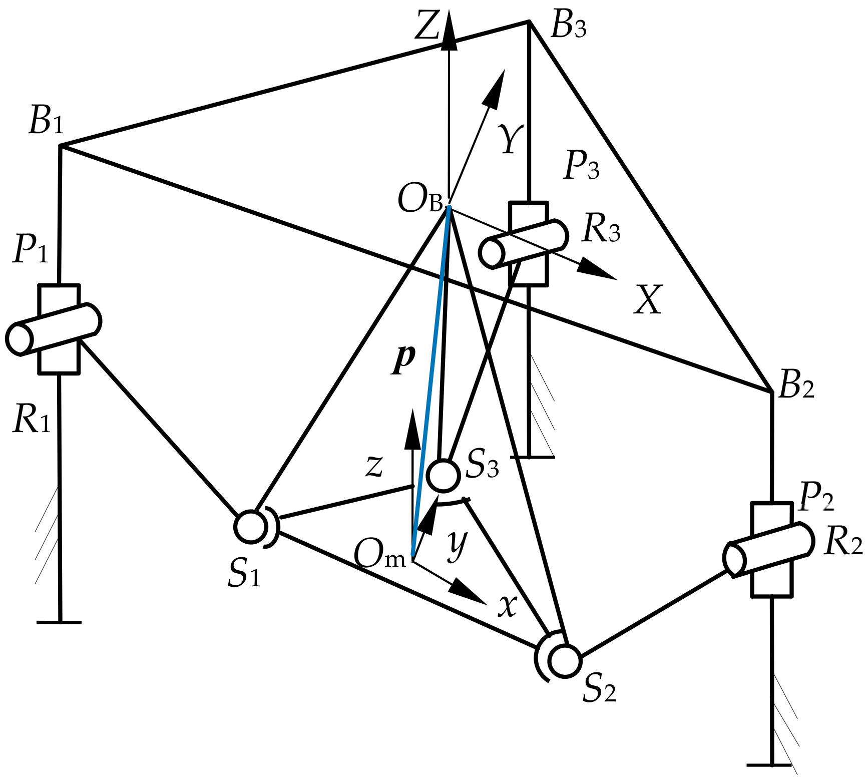
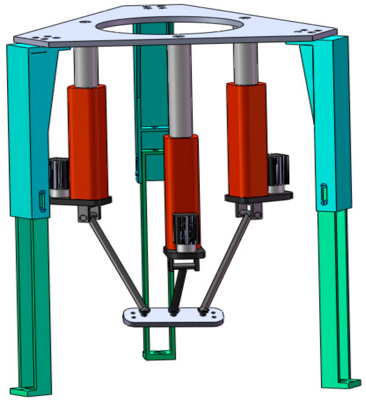
The 3-PRS PM includes a moving platform S1S2S3, a fixed platform B1B2B3, and three PRS branch chains. The prismatic joint is actuated by a linear actuator. The axis of the revolute joint Ri (i = 1, 2, 3) is perpendicular to the axis of the prismatic joint Pi. To facilitate the design and analysis of 3-PRS PMs, the fixed platform B1B2B3 is set as an equilateral triangle with circumradius R and a central point OB, and the moving platform S1S2S3 is also an equilateral triangle with circumradius r and a central point Om. The fixed platform and the moving platform are connected by three PRS branch chains. The spherical pair Si is evenly distributed 120° on the moving platform S1S2S3. This 3-PRS PM is called a 3-PRS PM I in this paper. The model is shown in Figure 1.
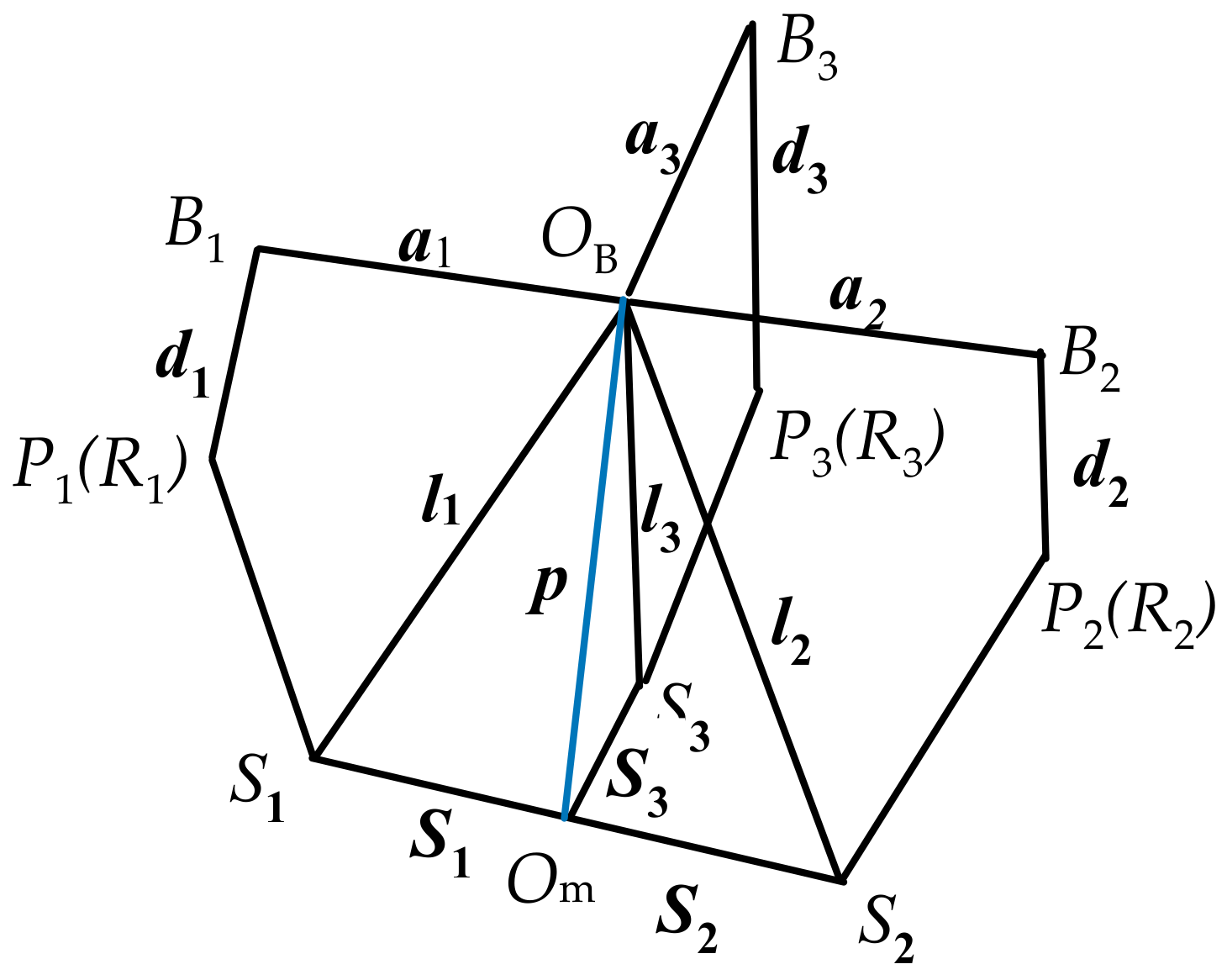
As shown in Figure 2, the fixed coordinate system OB-XYZ ({OB} for short) is connected to the origin OB of the fixed platform B1B2B3. The direction of the Y axis is from OB to B3. The direction of the X axis is parallel to B1B2. The Z axis is perpendicular to the plane B1B2B3 and the direction is upward.
The moving coordinate system Om-xyz ({Om} for short) is connected to the origin Om of the moving platform S1S2S3. The direction of the y axis is from Om to S3. The direction of the x axis is parallel to S1S2. The z axis is perpendicular to the plane S1S2S3 and the direction is upward.

2.2. Kinematics Analysis

The aim of kinematics analysis is to obtain the constraint equations according to the geometric characteristics of the PMs. In this paper, a y-x-z Euler angle is introduced to describe the posture of the moving platform in the {OB} coordinate system; that is, let the rotation angle around the y axis be first θ, then the rotation angle around the x axis can be ψ, and, finally, the rotation angle around the z axis can be ϕ. The rotation matrix T is:
T = T y x z = R y ( θ ) R x ( ψ ) R z ( φ ) = c θ c φ + s ψ s θ s φ c θ s φ + s ψ s θ c φ c ψ s θ c ψ s φ c ψ c φ s ψ s θ c φ + s ψ s θ s φ s θ s φ + s ψ c θ c φ c ψ c θ = T 11 T 12 T 13 T 21 T 22 T 23 T 31 T 32 T 33
where c represents the cosine and s represents the sine.
R y ( θ ) = cos θ 0 sin θ 0 1 0 sin θ 0 cos θ R x ( ψ ) = 1 0 0 0 cos ψ sin ψ 0 sin ψ cos ψ R z ( ϕ ) = cos φ sin φ 0 sin φ cos φ 0 0 0 1
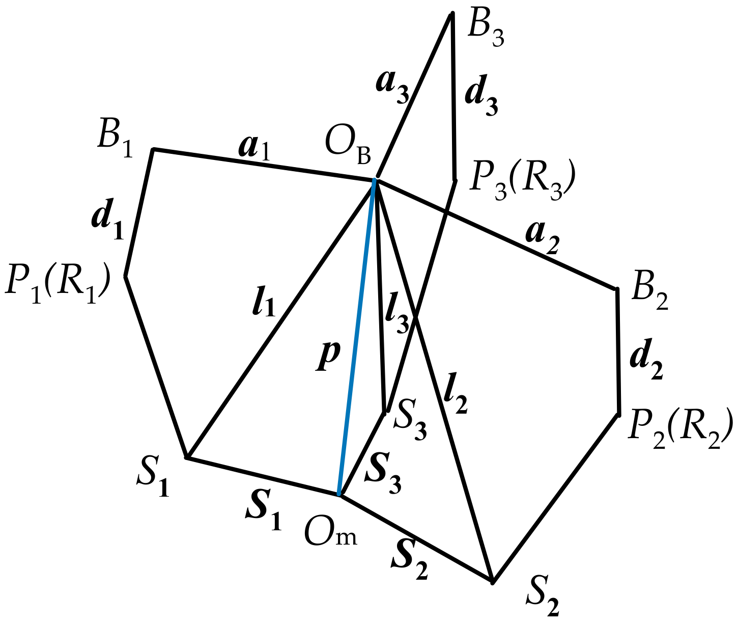
According to Figure 2 and Figure 3, the vectors of the joint position and motion direction are obtained, as shown in Table 1.
In the {OB} coordinate system, the vectors of the kinematic pairs of the three branch chains are as follows.
The position vectors of B1, B2, and B3 in the {OB} coordinate system are a1, a2, and a3:
a 1 = 3 R 2 R 2 0 T a 2 = 3 R 2 R 2 0 T a 3 = 0 R 0 T
The position vectors of the prismatic joint Pi (i = 1, 2, 3) in the {OB} coordinate system are:
P 1 = 3 R 2 R 2 d 1 T P 2 = 3 R 2 R 2 d 2 T P 3 = 0 R d 3 T
The position vectors of the spherical pairs S1, S2, and S3 in the {Om} coordinate system are S1′,S2′, and S3′:
S 1 = 3 r 2 r 2 0 T S 2 = 3 r 2 r 2 0 T S 3 = 0 r 0 T
The position vectors of the spherical pairs S1, S2, and S3 are represented as li (i = 1, 2, 3) in the {OB} coordinate system by S1′,S2′, and S3′ using the closed-loop vector method.
l i = S i + p = T S i + p
Substituting all the vectors aforementioned into Equation (5) yields:
l 1 x = x + T 11 b 1 x + T 12 b 1 y l 1 y = y + T 21 b 1 x + T 22 b 1 y
l 2 x = l 2 y = x + T 11 b 2 x + T 12 b 2 y y + T 21 b 2 x + T 22 b 2 y
l 3 x = x + T 12 b 3 y l 3 y = y + T 22 b 3 y
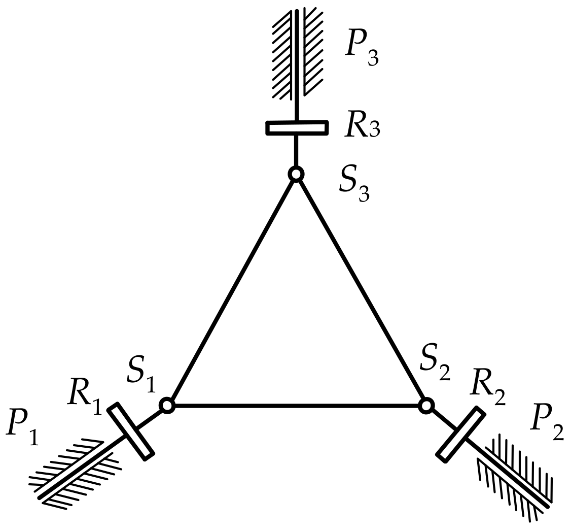
According to the constraints of the revolute pairs of the mechanism’s structure, each branch chain of the 3-PRS PM I only moves in the corresponding plane in Figure 4. Constrained by the structural conditions of the mechanism, each branch chain can obtain three constraint equations through Equation (6a–c) as follows:
l 1 y = 3 3 l 1 x
l 2 y = 3 3 l 2 x
l 3 x = 0
The solution of the vector p is obtained by combining Equations (6) and (7):
x = r cos θ sin φ sin ψ sin θ cos φ
y = r 2 ( 3 cos ψ sin φ + cos ψ cos φ + 3 cos θ sin φ 3 sin ψ sin θ cos φ cos θ cos φ sin ψ sin θ sin φ )
φ = arctan sin ψ sin θ cos ψ + cos θ
According to Equations (8)–(10), it is known that the moving platform S1S2S3 produces one rotation ϕ and two translation movements, x and y, of the moving platform center point Om along the x and y axes.
The small amplitude motions of the constrained degrees of freedom are called parasitic motions, that is the non-independent degrees of freedom, which are obtained by the constraint analysis of the center point of the moving platform. The existence of parasitic motion will cause the center point of the mechanism moving platform move in a non-direction of the degree of freedom, which brings great difficulties to the dimensional synthesis and trajectory planning of the mechanism. It will cause an effect on the precision of the mechanism and is harmful to the mechanism. The minimization and elimination of the parasitic motion have a significant influence on the practical application. Additionally, the motion parameter ϕ is related to the kinematic parameters ψ and θ. The motion parameters x and y are related to the structural parameter r and the kinematic parameters ψ and θ.

2.3. Parasitic Motion Analysis

The structural parameters of the 3-PRS PM I in Figure 1 are given in Table 2. The ranges of the kinematic parameters ψ and θ are [−60°, 60°], which fully satisfies the rotation angles required by the PM.
When the structural parameter r of the moving platform S1S2S3 is given as 250 mm, 175 mm, and 100 mm and the ranges of the kinematic parameters ψ and θ are all as [−60°, 60°], the parasitic motions x and y can be obtained through MATLAB, as shown in Figure 5 and Figure 6.
The CPU running times of the parasitic motions x with the moving platform m given as 250 mm, 175 mm, and 100 mm through MATLAB are 2.3400 s, 1.9968 s, and 1.9032 s, while the CPU running times of the parasitic motions y are 1.4820 s, 1.4976 s, and 1.5600 s.
When the circumradius r of the moving platform S1S2S3 is given as 250 mm, the kinematic parameters ψ and θ are given as from [−60°, 60°] to [−5°, 5°]. The motion parameter ϕ obtained through MATLAB is shown as in Figure 7.
The CPU running times of the motion parameter ϕ with kinematic parameters ψ and θ given as [−60°, 60°], [−30° 30°], and [−5°, 5°] through MATLAB are 1.9032 s, 0.4524 s, and 0.0936 s.
According to Figure 5 and Figure 6, the parasitic motions x and y are symmetrically distributed and the value of x and y at ψ and θ at [0, 0] is 0, that is, there is no parasitic motion occurring.
When given the ranges of the kinematic parameters ψ and θ, the maximum values of the parasitic motions x and y with the circumradius r = 250 mm and r = 100 mm of the moving platform S1S2S3 are obtained as outlined in Table 3.
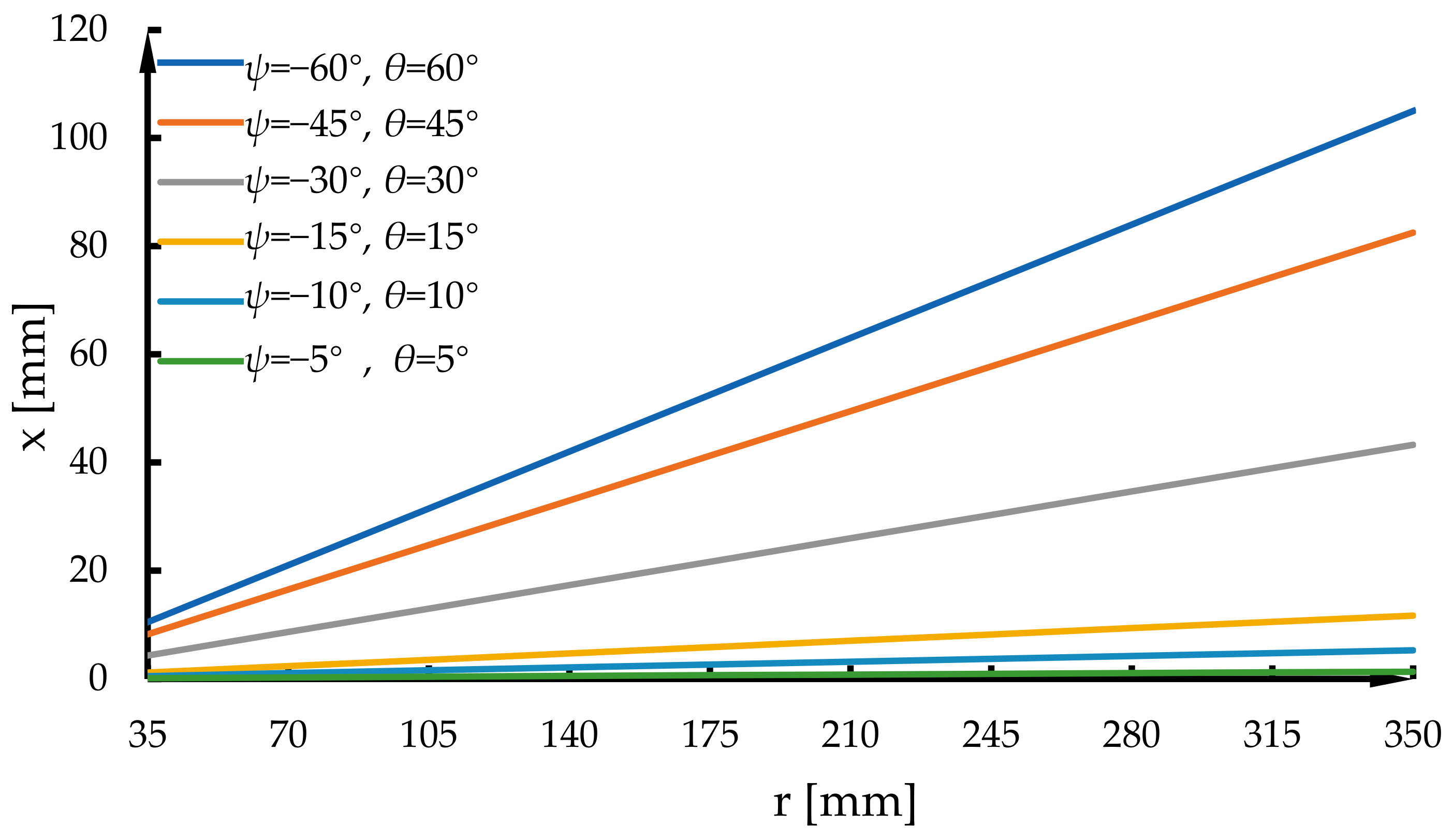
When given the ranges of the structural parameters r of the moving platform S1S2S3 as [35, 350] mm, the values of the parasitic motions x with the given ψ and θ has a linear relationship with the circumradius r, as shown in Figure 8.
When given the ranges of the structural parameters r of the moving platform S1S2S3 as [35, 350] mm, the values of the parasitic motions y with the given ψ and θ also have a linear relationship with the circumradius r, as shown in Figure 9.

2.4. Improved 3-PRS PM I without Parasitic Motion

As can be seen from Figure 5 and Figure 6, as the ranges of the kinematic parameters ψ and θ increase, the parasitic motions become more obvious. That is to say, when the structural parameters remain unchanged, the larger the workspace of the mechanism, the more obvious the parasitic motion is. When the kinematic parameters are in the smaller angle range, for instance, [−5°, 5°], the parasitic motions along with the movement are not obvious and can be neglected. However, when the amplitude variation in the kinematic parameters is bigger, the amplitude variation in the parasitic motions change and is also larger. That is, the parasitic motions are increasingly obvious, and the influence on the mechanism’s performance may be also increasing. Specifically, the parasitic motions reach the maximum when the PM moves to its limit position, which causes operation error and affects the running accuracy of the PM. Thus, in order to reduce or eliminate parasitic motions, it is important to optimize the design of the PM and kinematic parameters for the PMs used for large piece machining.
In order to avoid the parasitic motions of the 3-PRS PM I described in Section 2.1, Equations (8)–(10) are equal to 0 and are solved for the structural parameter r and the kinematic parameters ψ and θ; the value of the structural parameter r is 0. The improved 3-PRS PM I without parasitic motion is shown in Figure 10.
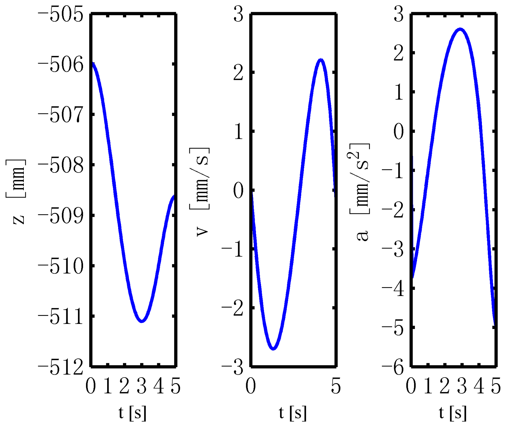
When given the structural parameters r and the kinematic parameters of the improved 3-PRS PM I, the displacement component z, the velocity, and acceleration of the moving platform S1S2S3 are solved as shown in Figure 11.

3. 3-PRS PM II

3.1. 3-PRS PM II Modeling

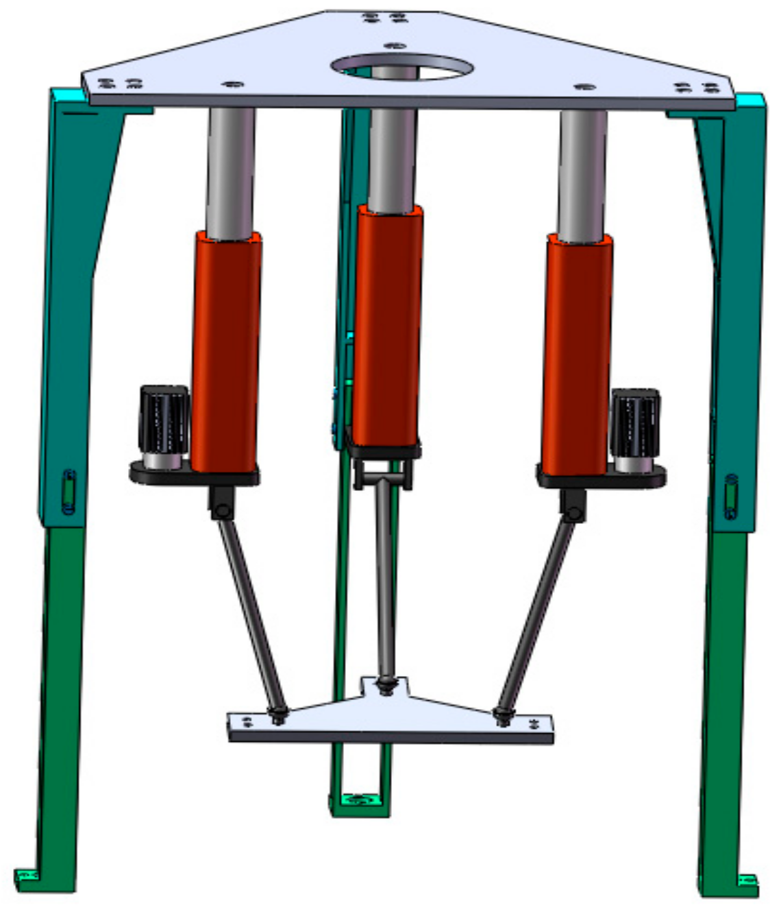
Set the fixed platform B1B2B3 and the moving platform S1S2S3 of 3-PRS PM as isosceles triangles. This 3-PRS PM is called as 3-PRS PM II in this paper and the model is shown in Figure 12.
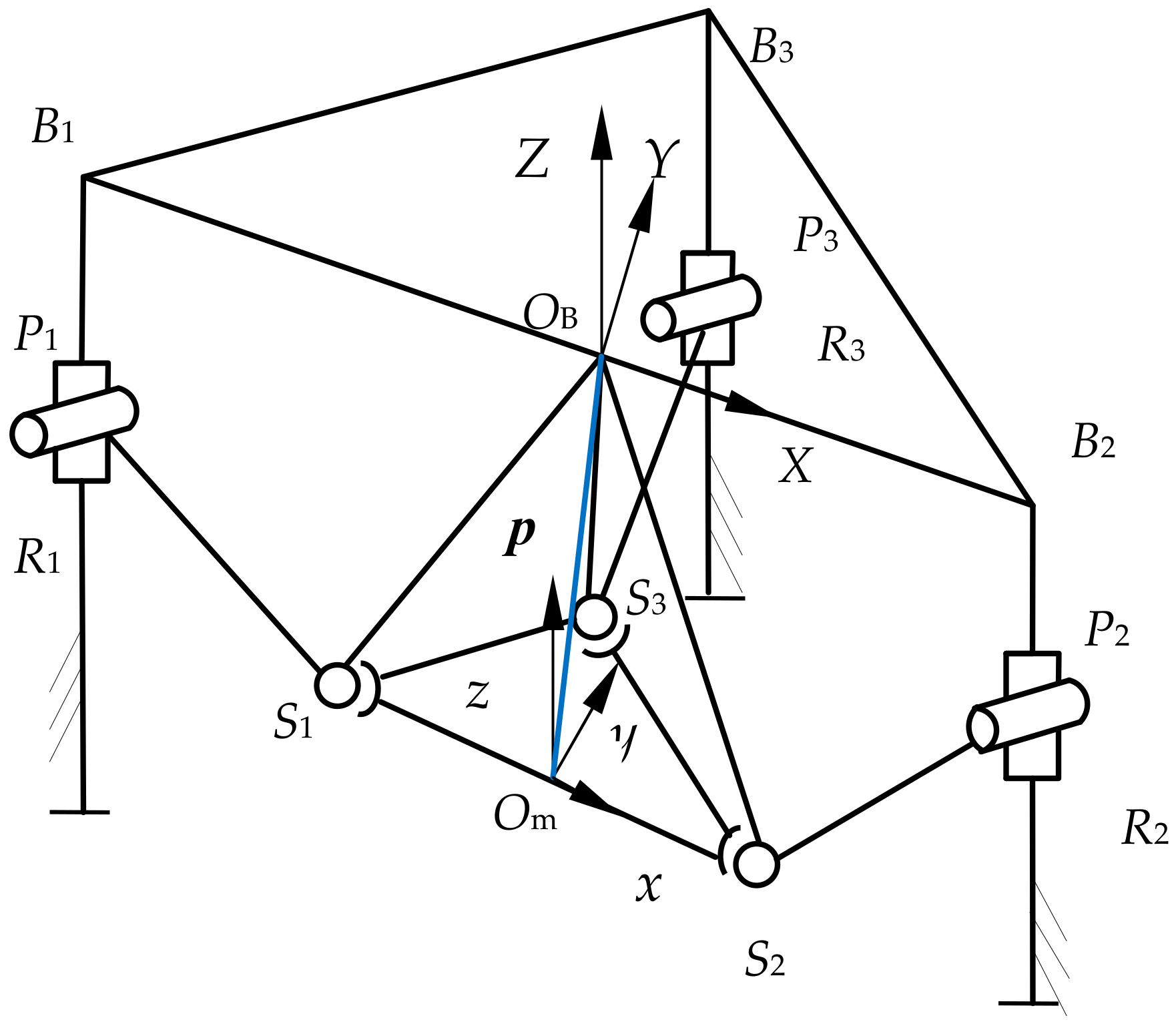
The length of side OBB3 is b and the length of sides B1B3 and B2B3 is a, while the length of side OmB3 is d and the length of the two sides b1b3 and b2b3 is c. Three PRS branch chains connect the fixed platform B1B2B3 and the moving platform S1S2S3. The mechanism diagram of the 3-PRS PM I is shown in Figure 13.
As shown in Figure 12, the fixed coordinate system OB-XYZ ({OB} for short) is connected to the origin OB of the fixed platform B1B2B3. The direction of the Y axis is from OB to B3. The direction of the X axis is from OB to B2. The Z axis is perpendicular to the fixed platform B1B2B3 and the direction is upward.
The moving coordinate system Om-xyz ({Om} for short) is connected to the origin Om of the moving platform S1S2S3. The direction of the y axis is from Om to S3. The direction of the x axis is from Om to S2. The z axis is perpendicular to the plane S1S2S3 and the direction is upward.

3.2. Kinematics Analysis

The joint position vectors and motion direction vectors are obtained, as shown in Table 1. According to Figure 13 and Figure 14, the vectors of the kinematic pairs of the three branches in the {OB} coordinate system are as follows.
The position vectors of B1, B2, and B3 in the {OB} coordinate system are a1, a2, and a3:
a 1 = a 0 0 T a 2 = a 0 0 T a 3 = 0 b 0 T
The position vectors of the prismatic joint Pi (i = 1, 2, 3) in the {OB} coordinate system are:
P 1 = a 0 d 1 T P 2 = a 0 d 2 T P 3 = 0 b d 3 T
The position vectors of the spherical pairs S1, S2, and S3 in the {Om} coordinate system are S1′, S2′, and S3′:
S 1 = c 0 0 T S 2 = c 0 0 T S 3 = 0 e 0 T
The position vectors of spherical pairs S1, S2, and S3 are represented as li (i = 1,2,3) in the {OB} coordinate system {B} by S1′, S2′, and S3′ using a closed loop vector method:
l i = S i + p = T S i + p
Substituting all the vectors aforementioned into Equation (14) yields:
l 1 x = x + T 11 S 1 x l 1 y = y + T 21 S 1 x
l 2 x = l 2 y = x + T 11 S 2 x y + T 21 S 2 x
l 3 x = x + T 12 S 3 y l 3 y = y + T 22 S 3 y
According to the constraints of the revolute pairs of the mechanism structure, each branch chain of the PM only moves in the corresponding plane as in Figure 15. Constrained by the structural conditions of the mechanism, each branch chain can obtain three constraint equations through Equations (15a)–(15c), as follows:
l 1 y = 0
l 2 y = 0
l 3 x = 0
The solution of vector p is obtained by combining Equation (16):
x = e sin ψ sin θ , y = 0 ,   ϕ = 0
According to Equation (17), it is known that the moving platform S1S2S3 produces one translation movement x of the moving platform center point along the axis x. The parasitic motion x is related to the structural parameter e and kinematic parameters ψ and θ. When the kinematic parameters ψ and θ and structural parameter e of the moving platform S1S2S3 are given, the parasitic motions x can be obtained.

3.3. Parasitic Motion Analysis

The model shown in Figure 12 was established in SolidWorks, and the structural parameters are given in Table 4.
The ranges of the kinematic parameters ψ and θ are also [−60°, 60°], which fully satisfies the rotation angles required by the PM.
When the structural parameters e of side OmS3 of the moving platform S1S2S3 are given as 250 mm, 175 mm, and 100 mm and the ranges of the kinematic parameters ψ and θ are given as [−60°, 60°], the parasitic motion x can be obtained through MATLAB, as shown in Figure 16.
The CPU running times of parasitic motions x with the length of side OmS3 of the moving platform S1S2S3 given as 250 mm, 175 mm, and 100 mm and obtained through MATLAB are 2.1060 s, 1.8564 s, and 1.6848 s.
When given the ranges of the kinematic parameters ψ and θ, the maximum values of the parasitic motions x with the circumradius e = 250 mm and e = 100 mm of the moving platform S1S2S3 are obtained as outlined in Table 5.
When the ranges of the structural parameters e of the moving platform S1S2S3 are given as [35, 350] mm, the values of the parasitic motions x with the given ψ and θ parameters have a linear relationship with the circumradius e, as shown in Figure 17.

3.4. Improved 3-PRS PM II without Parasitic Motion

In order to avoid the parasitic motions of the 3-PRS PM II described in Section 3.1, Equation (17) is equal to 0 and solved for the structural parameter e, and for the kinematic parameters ψ and θ, the value of the structural parameter e is 0. The improved 3-PRS PM II without parasitic motion is shown in Figure 18.
When given the structural parameters e and the kinematic parameters of the improved 3-PRS PM II, the displacement component Z, the velocity, and acceleration of the moving platform S1S2S3 are solved as shown in Figure 19.

4. Conclusions

The general 2R1T PMs not only produce motions in the direction of DOF, but they also produce parasitic motion which incomplete motion constrained in the directions of other DOFs, which results in all points of the moving platform moving in a specific direction. As an inherent kinematic feature of PMs, parasitic motion leads to complex kinematics, requires real-time compensation, and hinders calibration. To study the inherent relation between the parasitic motion and the structure of 3-PRS PMs, two improved 3-PRS PMs of different branch chain arrangements are proposed in this paper.
(1) The parasitic motions are obtained using the closed-loop vector method according to the constraint conditions. According to Section 2.3 and Section 3.3, it is known that parasitic motions are inherent kinematic features and vary with the configurations of the two mathematical models of 3-PRS PM I and II.
(2) The obtained parasitic motions are related to the kinematic parameters and structural parameters of 3-PRS PM through analysis. When the kinematic parameters vary in a relatively small range, for instance, [−5°, 5°], the parasitic motions are not obvious and can be ignored. When the kinematic parameters change greatly, the amplitude is relatively large and should be taken into account.
(3) Given the structural and kinematic parameters, the maximum and minimum of parasitic motions in the limit position are pointed out and two improved 3-PRS PMs without parasitic motions are obtained. According to Section 2.4 and Section 3.4, parasitic motion can be avoided in the configuration at the design stage.
The results show that parasitic motions have an influence on kinematic analysis, which is meaningful to traditional five-axis CNC machine tools while machining the parts of the complex structure. For the 2R1T PMs with mixed degrees of freedom, studying and clarifying the trajectory of motions is of great practical significance to the motion control, error compensation, and calibration of PMs.

Author Contributions

Y.Y. provided the ideas and wrote the paper manuscript. Y.Y. established the mathematical model and kinematics analysis. Y.Y. analyzed parasitic motions and data. W.W. and R.L. provided reviewing and editing. W.W. provided project administration and funding. Y.Z. obtained the resources. R.L. provided supervision. All authors have read and agreed to the published version of the manuscript.

Funding

This work was supported by Key Research and Development Program of Shanxi Province (Grant NO. 2022ZDYF082). This work was also supported by the Shanxi Province Central Guidance Local Science and Technology Development Fund Project (Grant NO. YDZJSX2022A030).

Institutional Review Board Statement

Not applicable.

Informed Consent Statement

Not applicable.

Data Availability Statement

Not applicable.

Conflicts of Interest

The authors declare no conflict of interest.

References

  1. Yao, J.T.; Gu, W.D.; Feng, Z.Q.; Chen, L.P.; Xu, Y.D.; Zhao, Y.S. Dynamic analysis and driving force optimization of a 5-DOF parallel manipulator with redundant actuation. Robot. Comput. Int. Manuf. 2017, 48, 51–58. [Google Scholar] [CrossRef]
  2. Carabin, G.; Scalera, L.; Wongratanaphisan, T. An energy-efficient approach for 3D printing with a linear Delta robot equipped with optimal springs. Robot. Comput. Int. Manuf. 2021, 67, 102045. [Google Scholar] [CrossRef]
  3. Rodriguez, E.; Alvares, A.J.; Jaimes, C. Conceptual design and dimensional optimization of the linear delta robot with single legs for additive manufacturing. J. Braz. Soc. Mech. Sci. Eng. 2019, 233, 095965181983691. [Google Scholar] [CrossRef]
  4. Yang, C.; Ye, W.; Li, Q.C. Review of the performance optimization of parallel manipulators. Mech. Mach. Theory 2022, 170, 104725. [Google Scholar] [CrossRef]
  5. Li, Y.G.; Liu, H.T.; Zhao, X.M.; Huang, T.; Chetwynd, D.G. Design of a 3-DOF PKM module for large structural component machining. Mech. Mach. Theory 2010, 45, 941–954. [Google Scholar] [CrossRef]
  6. Xie, F.G.; Mei, B.; Liu, X.J.; Zhang, J.B.; Yue, Y. Novel mode and equipment for machining large complex components. J. Mech. Eng. 2020, 56, 70–78. [Google Scholar] [CrossRef]
  7. López-Custodio, P.C.; Fu, R.; Dai, J.S.; Jin, Y. Compliance model of Exechon manipulators with an offset wrist. Mech. Mach. Theory 2022, 167, 104558. [Google Scholar] [CrossRef]
  8. Bi, Z.M.; Jin, Y. Kinematic modeling of Exechon parallel kinematic machine. Robot. Comput. Int. Manuf. 2011, 27, 186–193. [Google Scholar] [CrossRef]
  9. Liu, X.J.; Xie, F.G.; Wang, J.S. Current opportunities in the field of mechanisms in China. J. Mech. Eng. 2015, 51, 2–12. [Google Scholar] [CrossRef]
  10. Udomsap, T.; Chinchouryrang, S.; Liampipat, S.; Chanthasopeephan, T. Kinematics of platform stabilization using a 3-PRS parallel manipulator. ROBOMECH J. 2023, 10, 8. [Google Scholar] [CrossRef]
  11. Gallardo-Alvarado, J.; Orozco, H.; Rico, J.M. Kinematics of 3-RPS parallel manipulators by means of screw theory. Int. J. Adv. Manuf. Technol. 2008, 36, 598–605. [Google Scholar] [CrossRef]
  12. Tang, T.; Fang, H.; Zhang, J. Hierarchical design, laboratory prototype fabrication and machining tests of a novel 5-axis hybrid serial-parallel kinematic machine tool. Robot. Comput. Int. Manuf. 2020, 64, 101944. [Google Scholar] [CrossRef]
  13. Liu, M.; Gu, Q.; Yang, B.; Yin, Z.; Liu, S.; Yin, L.; Zheng, W. Kinematics model optimization algorithm for six degrees of freedom parallel platform. Appl. Sci. 2023, 13, 3082. [Google Scholar] [CrossRef]
  14. Shen, H.P.; Meng, Q.M.; Li, J.; Deng, J.M.; Wu, G.L. Kinematic sensitivity, parameter identification and calibration of a non-fully symmetric parallel Delta robot. Mech. Mach. Theory 2021, 161, 104311. [Google Scholar] [CrossRef]
  15. Rao, N.M.; Rao, K.M. Dimensional synthesis of a spatial 3-RPS parallel manipulator for a prescribed range of motion of spherical joints. Mech. Mach. Theory 2009, 44, 477–486. [Google Scholar] [CrossRef]
  16. Malyshev, D.; Rybak, L.; Carbone, G.; Semenenko, T.; Nozdracheva, A. Optimal design of a parallel manipulator for aliquoting of biomaterials considering workspace and singularity zones. Appl. Sci. 2022, 12, 2070. [Google Scholar] [CrossRef]
  17. Liu, S.Z.; Yu, Y.Q.; Zhu, Z.C.; Su, L.Y.; Liu, Q.B. Dynamic modeling and analysis of 3-RRS parallel manipulator with flexible links. J. Cent. South Univ. Technol. 2010, 17, 323–331. [Google Scholar] [CrossRef]
  18. Farhat, N.; Mata, V.; Alvaro, P.; Valero, F. Identification of dynamic parameters of a 3-DOF RPS parallel manipulator. Mech. Mach. Theory 2008, 43, 1–17. [Google Scholar] [CrossRef]
  19. Carretero, J.A.; Podhorodeski, R.P.; Nahon, M.A.; Gosselin, C.M. Kinematic analysis and optimization of a new three degree-of-freedom spatial parallel manipulator. J. Mech. Des. 2000, 122, 17–24. [Google Scholar] [CrossRef]
  20. Herrero, S.; Pinto, C.; Corral, J.; Altuzarra, O. Actuators orientation influence in the energy consumption of the 3-PRS manipulator. ASME Int. Mech. Eng. Congr. Expo. 2013, 15, 11. [Google Scholar] [CrossRef]
  21. Alshammari, S.; Al-Sawalha, M.M.; Shah, R. Approximate analytical methods for a fractional-order nonlinear system of Jaulent–Miodek equation with energy-dependent Schrödinger potential. Fractal Fract. 2023, 7, 140. [Google Scholar] [CrossRef]
  22. Al-Sawalha, M.; Ababneh, O.Y.; Shah, R.; Shah, N.A.; Nonlaopon, K. Combination of Laplace transform and residual power series techniques of special fractional-order non-linear partial differential equations. AIMS Math. 2023, 8, 5266–5280. [Google Scholar] [CrossRef]
  23. Al-Sawalha, M.M.; Shah, R.; Shah, N.A.; Nonlaopon, K.; Ababneh, O.Y. Numerical investigation of fractional-order wave-like equation. AIMS Math. 2023, 8, 5281–5302. [Google Scholar] [CrossRef]
  24. Al-Sawalha, M.M.; Shah, R.; Nonlaopon, K.; Khan, I.; Ababneh, O.Y. Fractional evaluation of Kaup–Kupershmidt equation with the exponential-decay kernel. AIMS Math. 2023, 8, 3730–3746. [Google Scholar] [CrossRef]
  25. Gallardo-Alvarado. An application of the newton-homotopy continuation method for solving the forward kinematic problem of the 3-RRS parallel manipulator. Math. Probl. Eng. 2019, 2019, 3123808. [Google Scholar] [CrossRef]
  26. Yang, G.; Zhu, R.; Fang, Z.; Chen, C.Y.; Zhang, C. Kinematic design of a 2R1T robotic end-effector with flexure joints. IEEE Access. 2020, 8, 57204–57213. [Google Scholar] [CrossRef]
  27. Liu, X.J.; Wu, C.; Wang, J.S.; BONEV, I. Attitude description method of [PP]S type parallel robotic mechanisms. Chin. J. Mech. Eng. 2008, 44, 19–23. [Google Scholar] [CrossRef]
  28. Li, Q.C.; Chen, Z.; Chen, Q.H.; Wu, C.Y.; Hu, X.D. Parasitic motion comparison of 3-PRS parallel mechanism with different limb arrangements. Robot. Comput. Int. Manuf. 2011, 27, 389–396. [Google Scholar] [CrossRef]
  29. Xu, Y.D.; Zhao, Y.; Yue, Y.; Xi, F.F.; Yao, J.T.; Zhao, Y.S. Type synthesis of overconstrained 2R1T parallel mechanisms with the fewest kinematic joints based on the ultimate constraint wrenches. Mech. Mach. Theory 2020, 147, 103766. [Google Scholar] [CrossRef]
  30. Hu, B.; Shi, D.S.; Shi, Y.G.; Zhang, D.; Ye, N.J. Kinematically identical manipulators for an asymmetric 3-PRS parallel manipulator and their constraint performance comparison study. J. Mech. Eng. 2020, 56, 31–40. [Google Scholar] [CrossRef]
  31. Jha, R.; Chablat, D.; Baron, L. Influence of design parameters on the singularities and workspace of a 3-RPS parallel robot. Trans. Can. Soc. Mech. Eng. 2018, 42, 30–37. [Google Scholar] [CrossRef]
  32. Fang, H.; Xin, B.; Zhang, X. Workspace-constrained optimal design of three-degrees-of-freedom parallel manipulators with minimum parasitic motions by integrating interval analysis, region mapping and differential evolution. Eng. Optimiz. 2015, 47, 407–428. [Google Scholar] [CrossRef]
  33. Chen, M.; Zhang, Q.; Chen, W.T.; Qin, X.R.; Sun, Y.T. Analysis and type synthesis of parallel mechanisms without parasitic motion based on spatial geometry. J. Mech. Eng. 2021, 57, 77–85. [Google Scholar] [CrossRef]
  34. Hao, L.L.; Li, H.; Li, R.Q. Workspaces solution of 3-PRS parallel mechanism with simmechanics. Mach. Des. Manuf. 2016, 11, 63–65. (In Chinese) [Google Scholar] [CrossRef]
  35. Xia, H.; Zhao, Y.H.; Li, R.Q. Concomitant Motion and Positive and Inverse Solutions of UPS+UPR+S Parallel Mechanism. Pack. Eng. 2018, 7, 136–140. (In Chinese) [Google Scholar] [CrossRef]
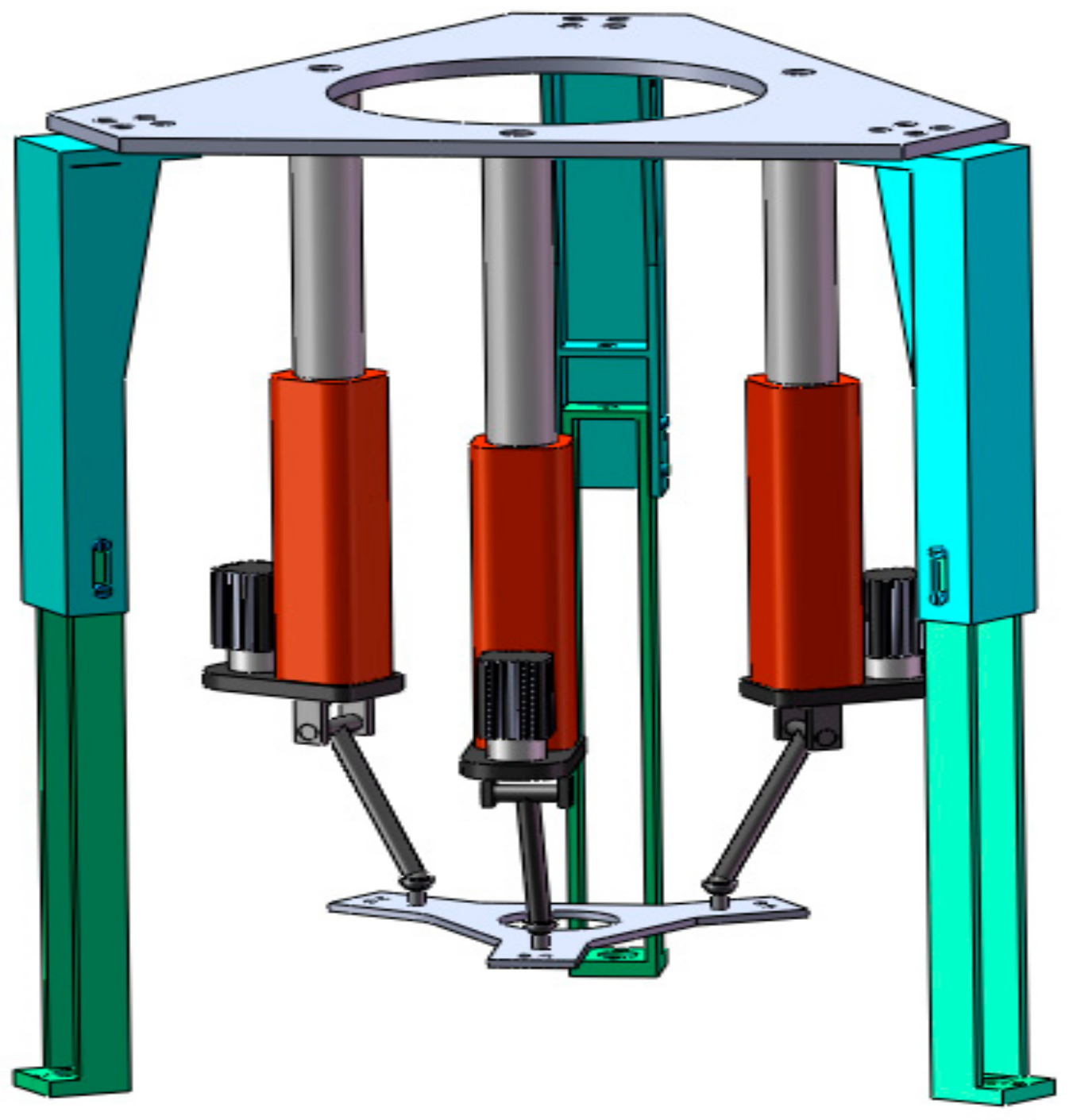
Figure 1. 3-PRS PM I.
Applsci 13 05425 g001
Figure 2. Schematic diagram of 3-PRS PM I.
Applsci 13 05425 g002
Figure 3. Vector diagram of 3-PRS PM I.
Applsci 13 05425 g003
Figure 4. Diagram of branch chain distribution.
Applsci 13 05425 g004
Figure 5. Variations in the parasitic motion x with different moving platform circumradius r. (a) r = 250 mm, (b) r = 175 mm, and (c) r = 100 mm.
Applsci 13 05425 g005
Figure 6. Variations in the parasitic motion y with different moving platform circumradius r. (a) r = 250 mm, (b) r = 175 mm, and (c) r = 100 mm.
Applsci 13 05425 g006
Figure 7. Variations in the parasitic motion ϕ with kinematic parameters ψ and θ while r = 250 mm. (a) ψ and θ ∈ [−60°, 60°], (b) ψ and θ ∈ [−30°, 30°], and (c) ψ and θ ∈ [−5°, 5°].
Applsci 13 05425 g007
Figure 8. Variations in the parasitic motion x with circumradius r ∈ [35, 350] mm.
Applsci 13 05425 g008
Figure 9. Variations in the parasitic motion y with circumradius r ∈ [35, 350] mm.
Applsci 13 05425 g009
Figure 10. Improved 3-PRS PM I.
Applsci 13 05425 g010
Figure 11. Solved results of S1S2S3.
Applsci 13 05425 g011
Figure 12. 3-PRS PM II.
Applsci 13 05425 g012
Figure 13. Diagram of 3-PRS PM II.
Applsci 13 05425 g013
Figure 14. Vector diagram of 3-PRS PM II.
Applsci 13 05425 g014
Figure 15. Diagram of branch chain distribution.
Applsci 13 05425 g015
Figure 16. Variations in the parasitic motion x with structural parameter e. (a) e = 250 mm, (b) e = 175 mm, and (c) e = 100 mm.
Applsci 13 05425 g016
Figure 17. Variations in the parasitic motion x with structural parameter e ∈ [35 350] mm.
Applsci 13 05425 g017
Figure 18. Improved 3-PRS PM II.
Applsci 13 05425 g018
Figure 19. Solved results of S1S2S3.
Applsci 13 05425 g019
Table 1. Joint position vectors and motion direction vectors.
ExpressionPhysical Meaning (i = 1, 2, 3)
p = x y z T In the {OB} coordinate system, the vector from the origin OB to the origin Om.
a i = a i x a i y a i z T In the {OB} coordinate system, the vector from the origin OB to point Bi.
l i = l i x l i y l i z T In the {OB} coordinate system, the vector from the origin OB to the spherical joint center Si.
S i = S ix S i y S i z T In the {OB} coordinate system, the vector from the origin Om to the spherical joint center Si.
S i = S i x S i y S i z T In the {Om} coordinate system, the vector from the origin Om to the spherical joint center Si.
d i The moving distance of the prismatic pair Pi
Table 2. Structural parameters of 3-PRS PM I.
ParameterValue
Equivalent circumradius of the fixed platform B1B2B3, R [mm]125
Equivalent circumradius of the moving platform S1S2S3, r [mm]80
Range of the moving distance of the pairs Pi, di [mm][105, 195]
Ranges of the kinematic parameters ψ and θ[−60°, 60°]
Table 3. Variations in the parasitic motions x and y with the kinematic parameters ψ and θ.
Anglesx-Max [mm] (r = 250)x-Max [mm] (r = 100)y-Max [mm] (r = 250)y-Max [mm] (r = 100)
ψ and θ ∈ [−60°, 60°]80.678932.271662.500025
ψ and θ ∈ [−45°, 45°]58.925623.570236.611714.6447
ψ and θ ∈ [−30°, 30°]30.929512.371816.74686.6987
ψ and θ ∈ [−15°, 15°]8.36843.34744.25931.7037
ψ and θ ∈ [−10°, 10°]3.76881.50751.89900.7596
ψ and θ ∈ [−5°, 5°]0.94950.37980.47570.1903
Table 4. Structural parameters of 3-PRS PM II.
ParameterValue
Length of side OBS2 of the fixed platform B1B2B3, a [mm]125
Length of side OBB3 of the fixed platform B1B2B3, b [mm]150
Length of side OmS2 of the moving platform S1S2S3, c [mm]80
Length of side OmS3 of the moving platform S1S2S3, e [mm]60
Range of the equivalent link length of the pairs Pi, di [mm][105, 195]
Ranges of the kinematic parameters ψ and θ[−60°, 60°]
Table 5. Variations in parasitic motion x with kinematic parameters ψ and θ.
Angles ψ and θx-Max [mm] (e = 250)x-Max [mm] (e = 100)
ψ and θ ∈ [−60°, 60°]187.575
ψ and θ ∈ [−45°, 45°]12550
ψ and θ ∈ [−30°, 30°]62.525
ψ and θ ∈ [−15°, 15°]16.756.6987
ψ and θ ∈ [−10°, 10°]7.53843.0154
ψ and θ ∈ [−5°, 5°]1.89900.7596
Disclaimer/Publisher’s Note: The statements, opinions and data contained in all publications are solely those of the individual author(s) and contributor(s) and not of MDPI and/or the editor(s). MDPI and/or the editor(s) disclaim responsibility for any injury to people or property resulting from any ideas, methods, instructions or products referred to in the content.