
Bearing Capacities and Failure Behaviors of F-Type Socket Joint in Rectangular Pipe Jacking Tunnel

Abstract
:1. Introduction
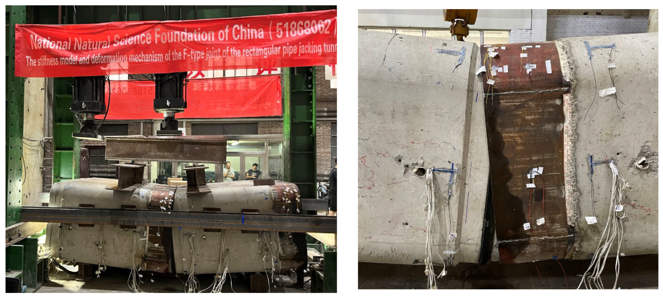
2. Full-Scale Experiments
2.1. Experiments Background
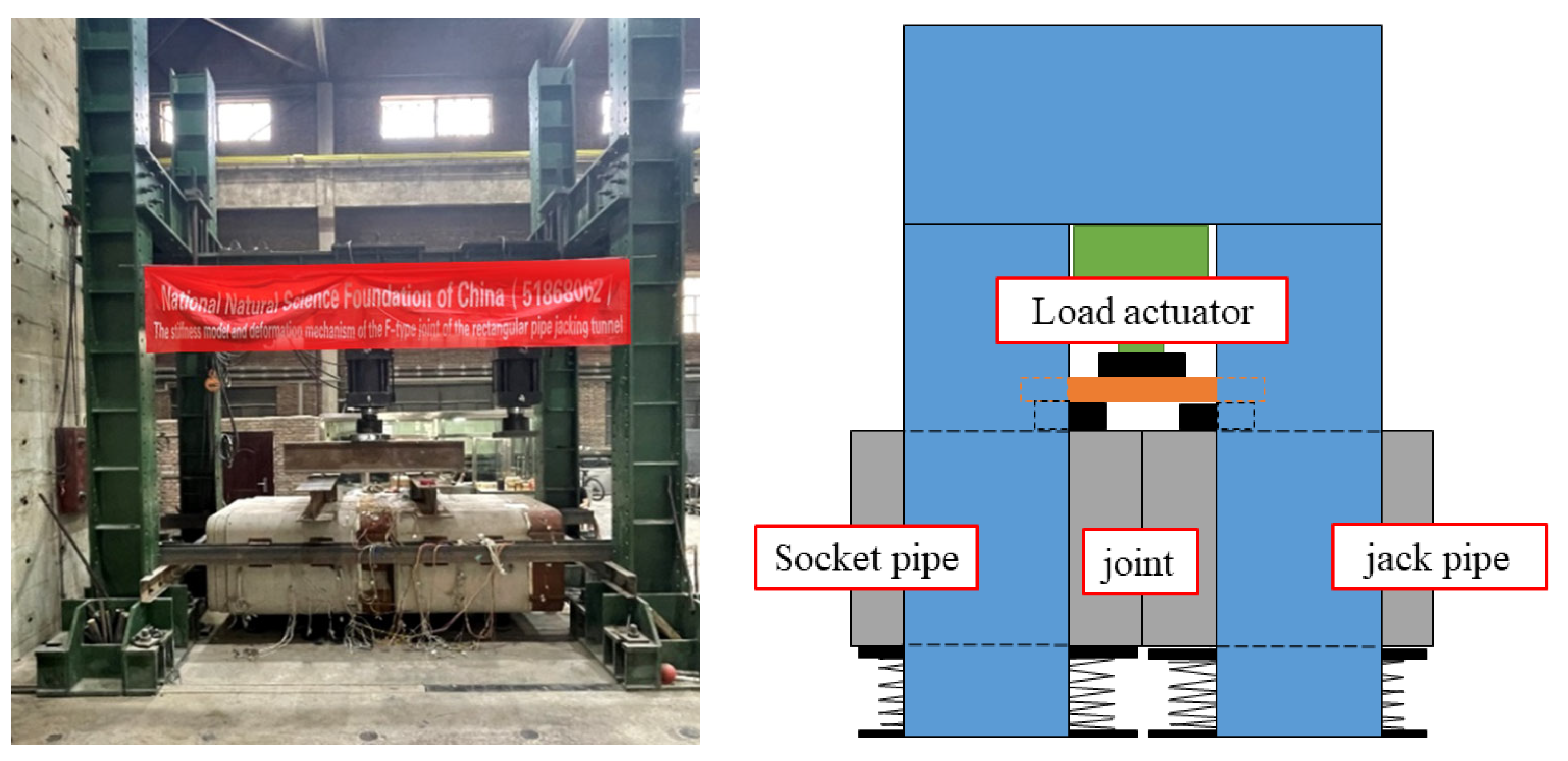
2.2. Test Overview Rectangle Pipe Jacking
2.3. Analysis of Test Data
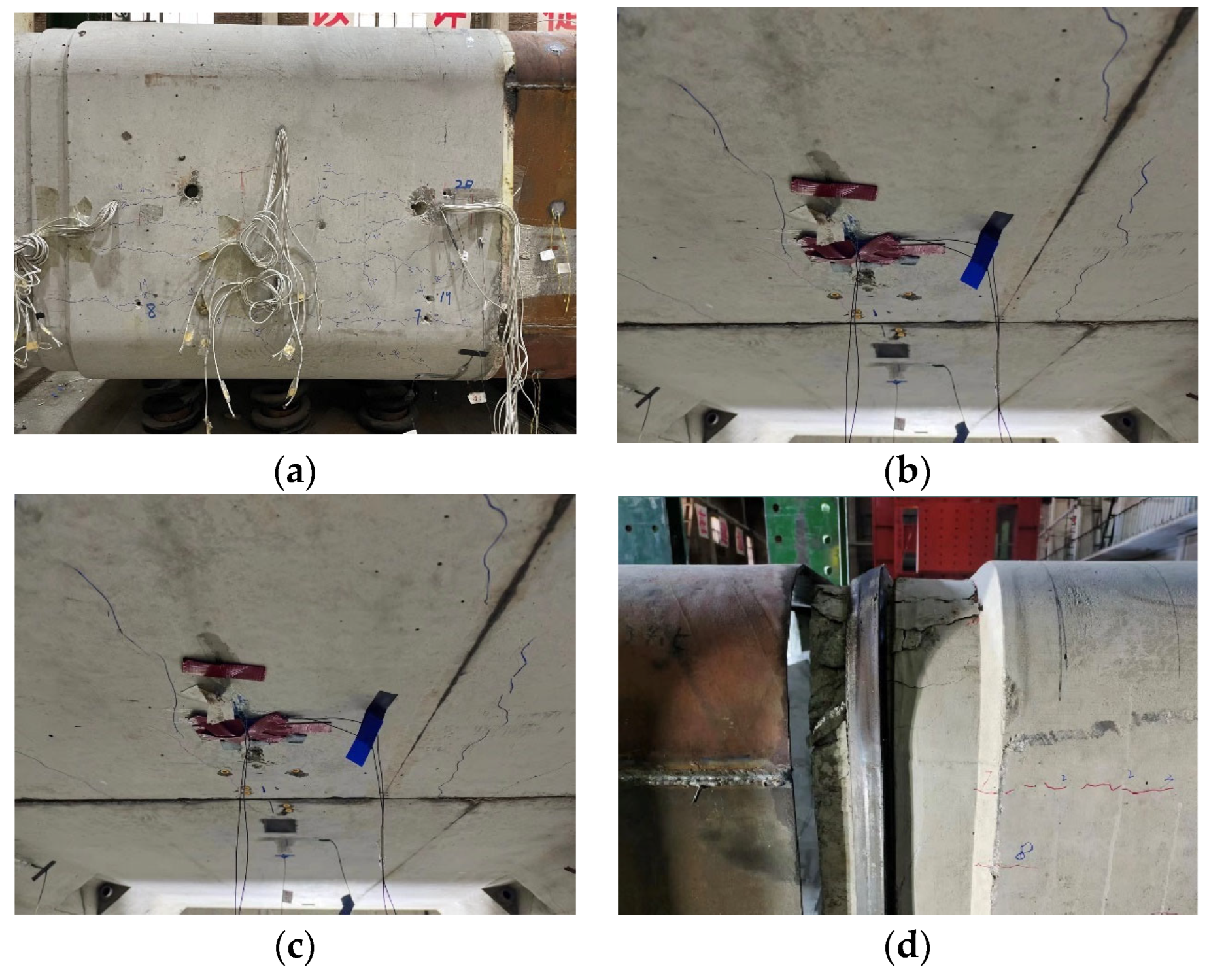
2.3.1. Failure Behaviors
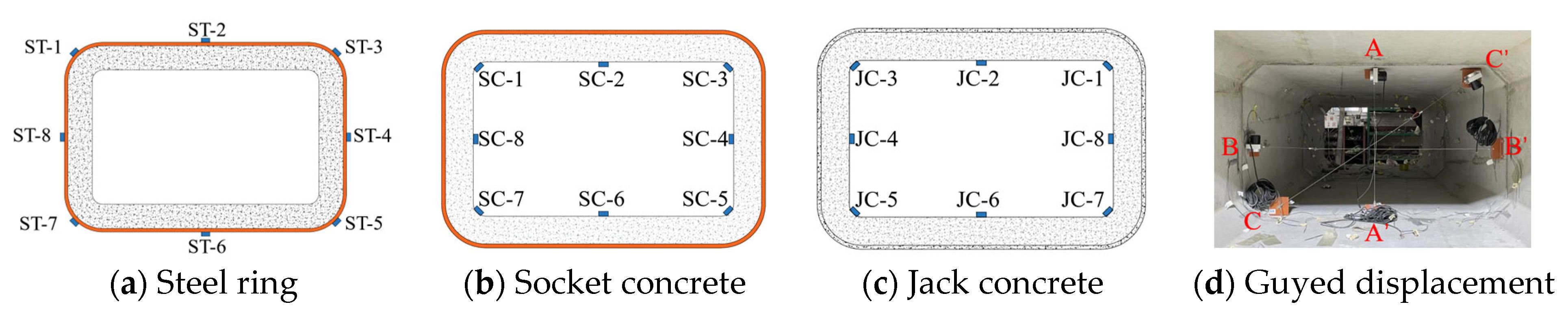
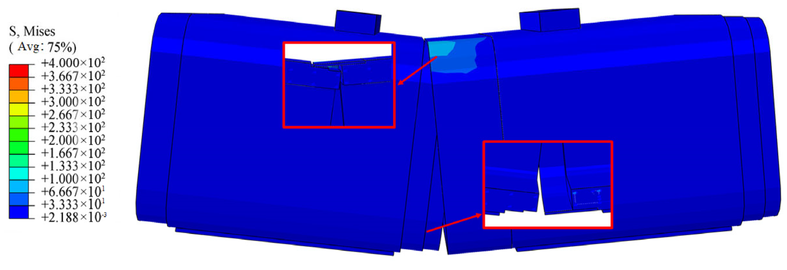
2.3.2. Stress Deformation of Pipe Joint
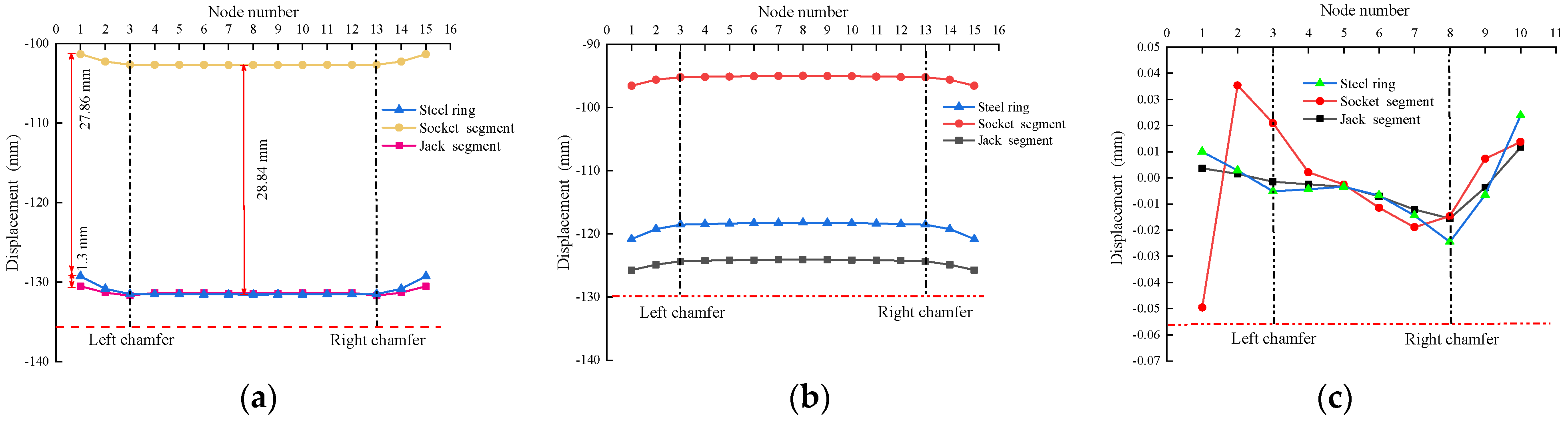
2.3.3. Deformation of Pipe Joint Section
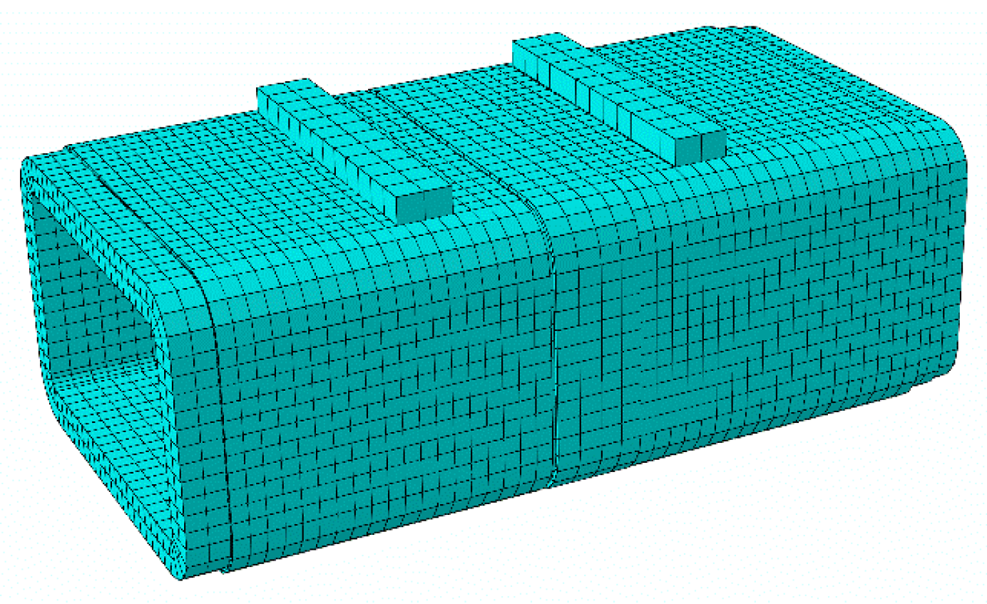
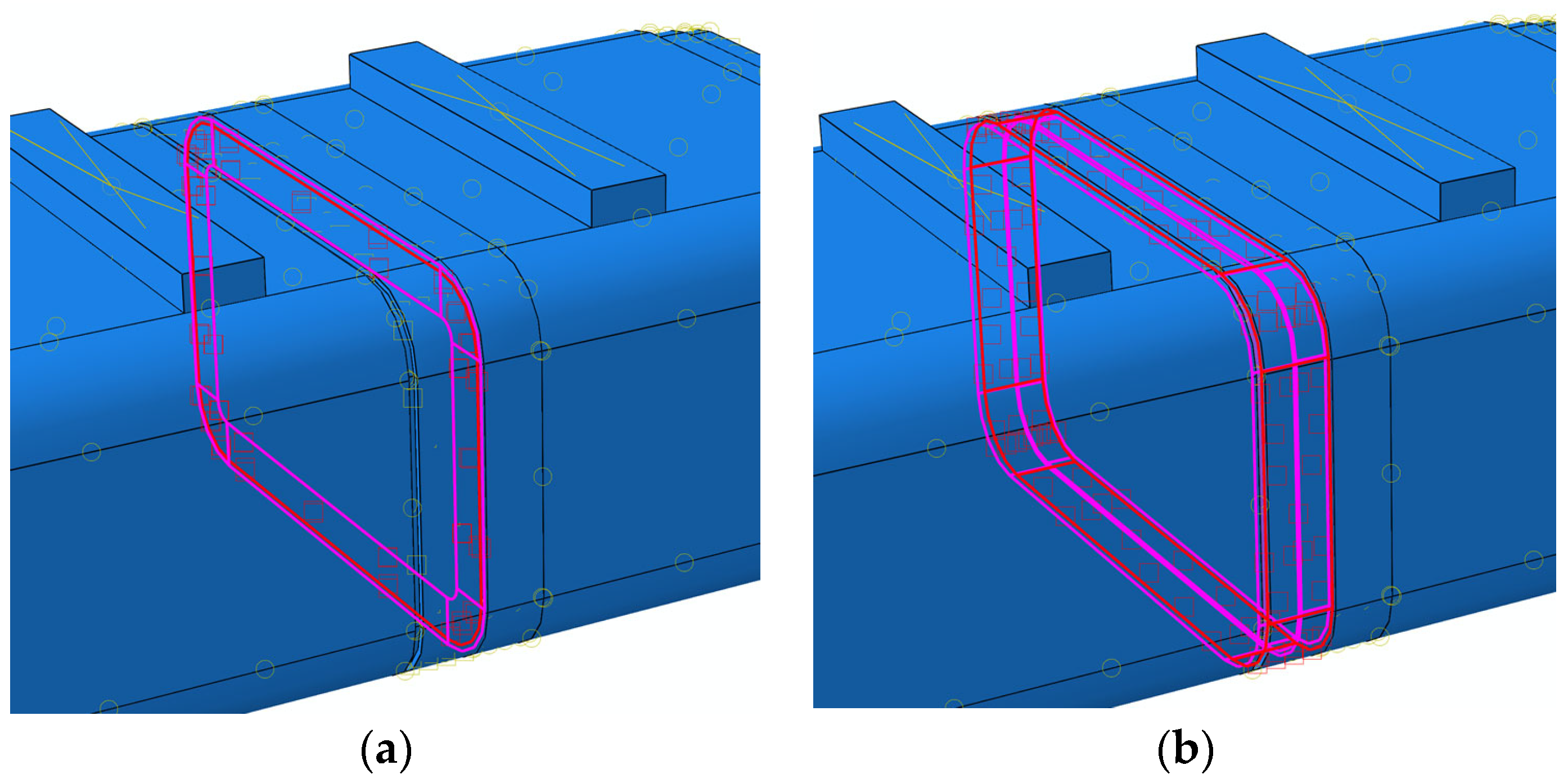
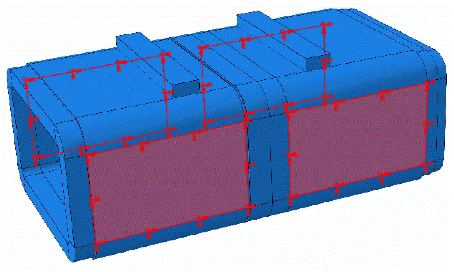
3. Numerical Simulations
3.1. Model Size and Material Parameters
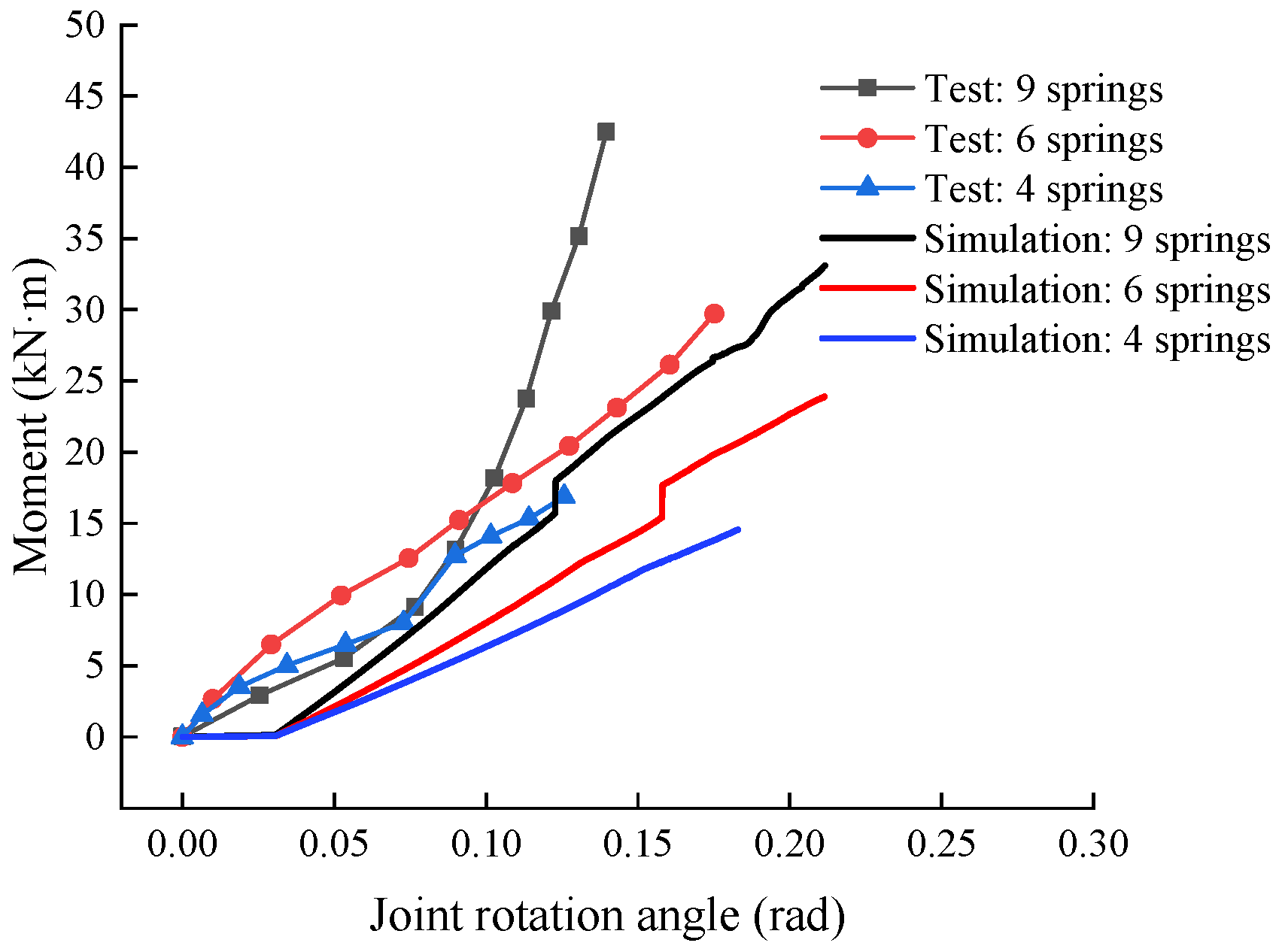
3.2. Numerical Results and Comparisons to the Tests
4. Parametric Analysis
4.1. Analysis of Cross-Sectional Dimensions
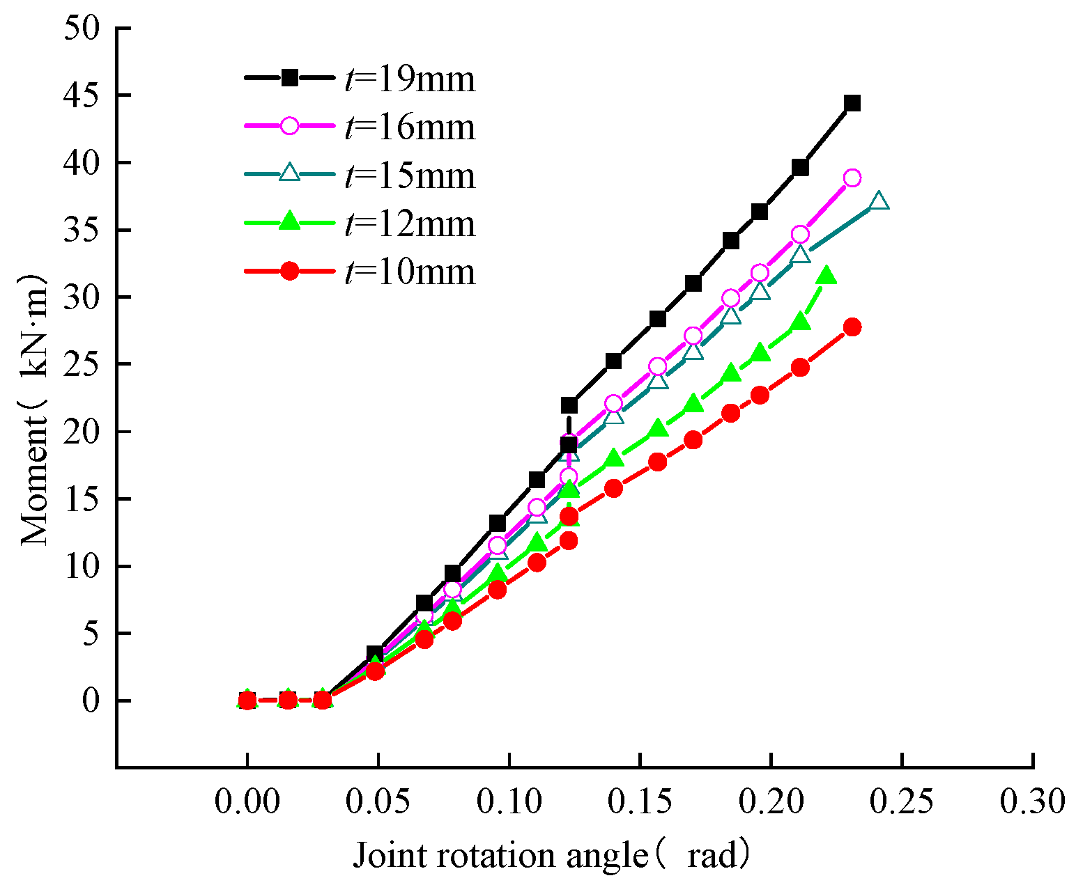
4.2. Analysis of Steel Ring Dimensions
5. Conclusions
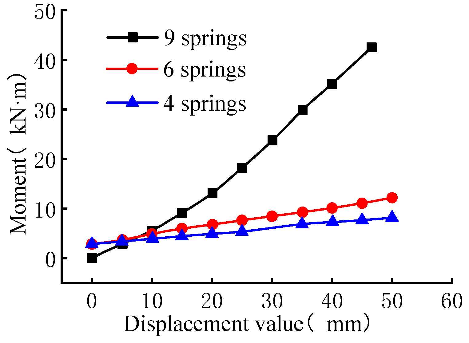
- (1)
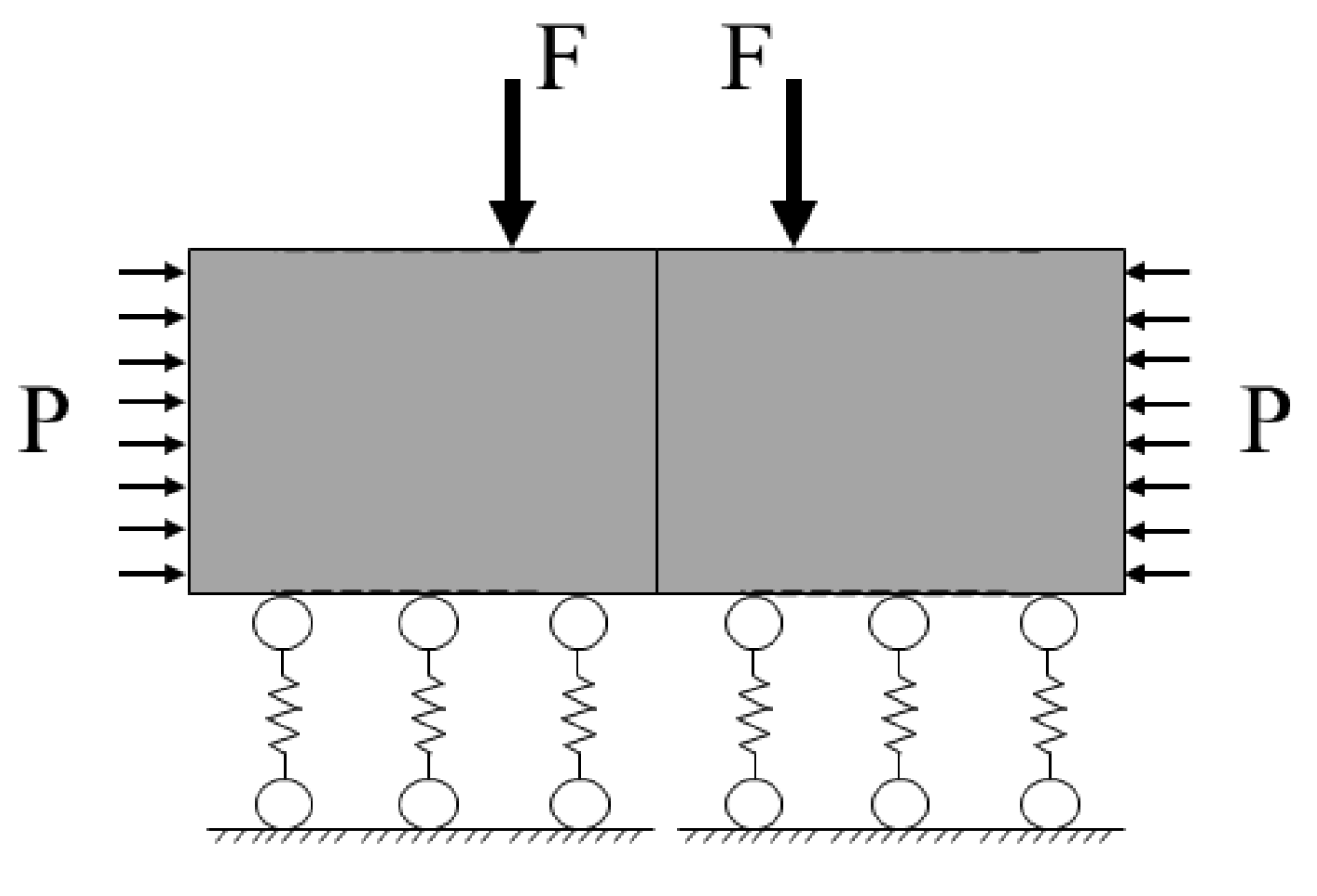
- Under the same loading displacement, the greater the foundation stiffness, the greater the bending moment borne by the joint, and the higher the joint bending capacity. The bending moment of the joint is mainly borne by the steel ring, which will eventually be damaged by bending.
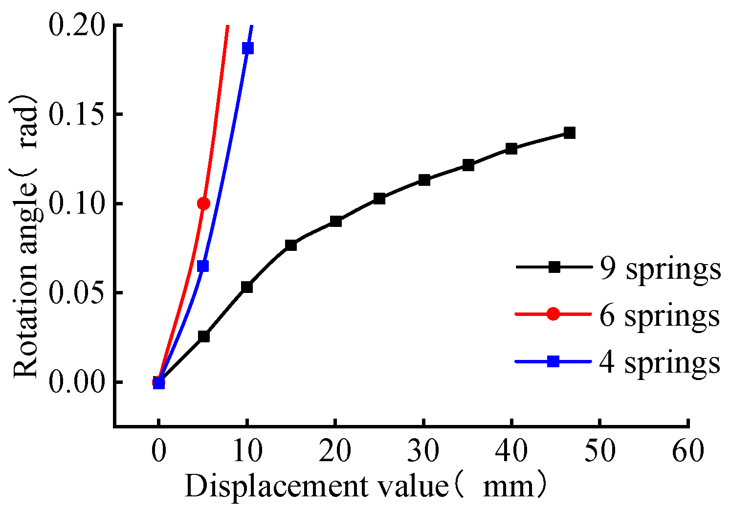
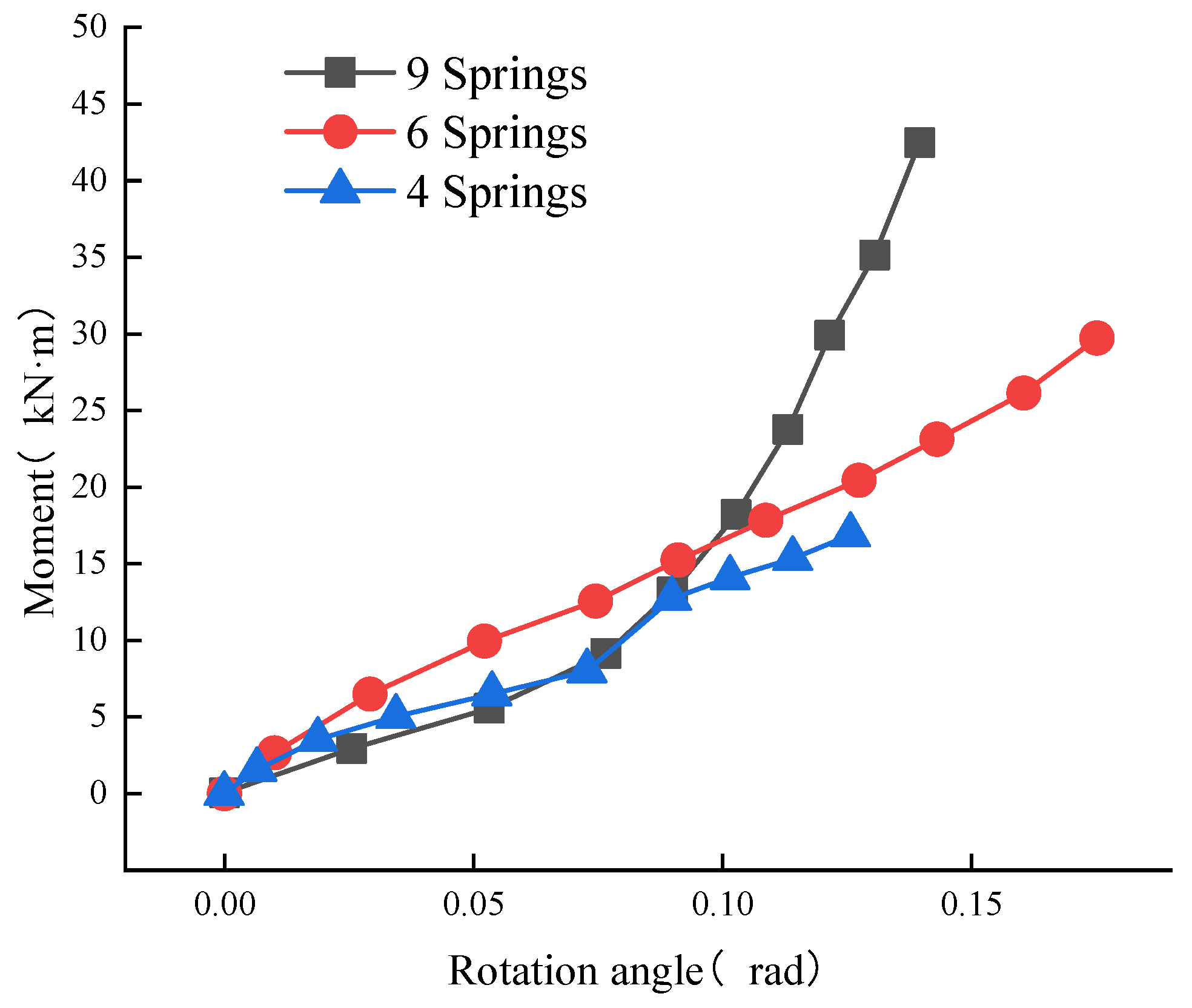
- (2)
- The change of joint opening is closely related to the change of joint bending moment; the larger the joint bending moment, the larger the corresponding joint opening. In addition, the larger deformation of the pipe joint itself will lead to a slower rate of change of the joint opening, resulting in an increase in the slope of the joint bending stiffness.
- (3)
- The deformation of the pull-wire displacement gauge at the joint, the concrete strain and the steel collar strain show the same change pattern, which all indicate that the joint tends to be flattened during the bending loading process.
- (4)
- The deformation of the steel collar is closely related to the deformation of concrete, and the two are in the same state of stress at the same position. In addition, the top bottom plate of the steel ring will be warped near the socket side, and the degree of warping is most obvious at the axillary corner of the top bottom plate due to stress concentration. When the bottom of the pipe joint is separated from the socket end, the structure is eventually deformed due to the large deformation of the bottom of the pipe joint.
- (5)
- Joint bending deformation is influenced by the foundation stiffness of the strata. The larger the foundation stiffness and the harder the strata, the smaller the joint bending deformation; the larger the section size of the pipe joint, the smaller the joint bending deformation; the larger the size of the steel collar, the smaller the joint bending deformation.
Author Contributions
Funding
Institutional Review Board Statement
Informed Consent Statement
Data Availability Statement
Conflicts of Interest
References
- Chapman, D.N.; Ichioka, Y. Prediction of jacking forces for microtunnelling operations. Tunn. Undergr. Space Technol. 1999, 14, 31–41. [Google Scholar] [CrossRef]
- Shimada, H.; Khazaei, S.; Matsui, K. Small diameter tunnel excavation method using slurry pipe-jacking. Geotech. Geol. Eng. 2004, 22, 161–186. [Google Scholar] [CrossRef]
- Khazaei, S.; Shimada, H.; Kawai, T.; Yotsumoto, J.; Matsui, K. Monitoring of over cutting area and lubrication distribution in a large slurry pipe jacking operation. Geotech. Geol. Eng. 2006, 24, 735–755. [Google Scholar] [CrossRef]
- Zhou, S.; Wang, Y.; Huang, X. Experimental study on the effect of injecting slurry inside a jacking pipe tunnel in silt stratum. Tunn. Undergr. Space Technol. 2009, 24, 466–471. [Google Scholar] [CrossRef]
- Zhang, Q.S.; Zhang, L.Z.; Liu, R.T.; Li, S.C.; Zhang, Q.Q. Grouting mechanism of quick setting slurry in rock fissure with consideration of viscosity variation with space. Tunn. Undergr. Space Technol. 2017, 70, 262–273. [Google Scholar] [CrossRef]
- Zhang, Y.; Yan, Z.; Zhu, H.; Ju, J. Experimental study on the structural behaviors of jacking prestressed concrete cylinder pipe. Tunn. Undergr. Space Technol. 2018, 73, 60–70. [Google Scholar] [CrossRef]
- Sterling, R.L. ScienceDirect Developments and research directions in pipe jacking and microtunneling. Undergr. Space 2020, 5, 1–19. [Google Scholar] [CrossRef]
- Zheng, H.B.; Li, P.F.; Ma, G.W.; Zhang, Q.B. Experimental investigation of mechanical characteristics for linings of twins tunnels with asymmetric cross-section. Tunn. Undergr. Space Technol. 2022, 119, 104209. [Google Scholar] [CrossRef]
- Liu, W.J.; Fu, H.L.; Wen, S.J.; Guo, H.X. Influencing analysis of construction of mining tunnel close crossing underneath the existing rectangular pipe jacking tunnel. J. Railw. Sci. Eng. 2016, 13, 1782–1788. (In Chinese) [Google Scholar]
- Liu, B.; Zhang, D.W.; Liu, S.Y. Numerical simulation and field monitoring on a large cross-section pipe-jacking underpass traversing existing metro tunnels. J. Rock Mech. Eng. 2017, 36, 2850–2860. (In Chinese) [Google Scholar]
- Wei, G.; Huang, Z.Y.; Xu, R.Q. Study on calculation methods of ground deformation induced by pipe jacking construction. J. Rock Mech. Eng. 2005, 24, 5808–5815. (In Chinese) [Google Scholar]
- Wei, G.; Wei, X.J.; Tu, Y.M. Analysis of site monitoring of ground deformation induced by parallel pipe jacking construction. J. Rock Mech. Eng. 2006, 25, 3299–3304. (In Chinese) [Google Scholar]
- Wei, G.; Chen, C.L.; Yu, J.Y. Study on calculating methods of soil vertical deformation induced by pipe jacking construction. Geotechnics 2007, 28, 619–624. (In Chinese) [Google Scholar]
- Chen, X.L.; Ma, B.S.; Mohammad, N. Long rectangular box jacking project: A case study. Undergr. Space 2019, 6, 101–125. [Google Scholar] [CrossRef]
- Xu, Y.J.; Shi, M.L.; Li, Y.F. Study on vertical deformation of ground surface caused by construction of large section soil pressure balanced rectangular pipe jacking. Eng. J. Wuhan Univ. 2020, 53, 597604. (In Chinese) [Google Scholar]
- Yang, X.; Zhang, M.; Lai, Y.S. Theoretical and experimental analyses of jacking force during deep-buried pipe jacking. Rock Soil Mech. 2013, 34, 757–761. (In Chinese) [Google Scholar]
- Shi, P.X.; Yu, C.C.; Pan, J.J. Analysis on the jacking load of the curved pipe roof supporting the large diameter Gongbei tunnel. Chin. J. Rock Mech. Eng. 2017, 36, 2251–2259. (In Chinese) [Google Scholar]
- Xiang, A.T.; Zhu, H.H.; Ding, W.Q. Relationship of jacking force and average friction with jacking path in pipe-jacking construction. Rock Soil Mech. 2008, 29, 1005–1009. (In Chinese) [Google Scholar]
- Wang, S.; Xia, C.C.; Ge, J.K. Formulae of lateral friction resistance for pipe-jacking considering different forms of mud screen. Rock Soil Mech. 2014, 35, 159–166+174. (In Chinese) [Google Scholar]
- Ma, P.; Hideki, S.; Takashi, S. Investigation on the engineering effects of the geometrical configuration of the jacking rectangular pipe. Tunn. Undergr. Space Technol. 2020, 119, 104239. [Google Scholar] [CrossRef]
- Wei, G.; Wei, X.J.; Xu, R.Q. Study on soil-compacting effects induced by pipe jacking construction. Rock Soil Mech. 2006, 27, 717–722. (In Chinese) [Google Scholar]
- Xu, Y.J.; Wen, Z.K.; Yan, C.H. Experimental study on soil improvement during construction of EPB rectangular pipe jacking with multi-cutter. Chin. J. Geotech. Eng. 2016, 38, 288–296. (In Chinese) [Google Scholar]
- Ma, P.; Hideki, S.; Takashi, S. A new method for predicting the friction resistance in rectangular pipe-jacking. Tunn. Undergr. Space Technol. 2021, 123, 104338. [Google Scholar] [CrossRef]
- Liu, S.; Zhang, B.; Zhang, X. Formulation optimization and performance analysis of the thixotropic slurry for large-section rectangular pipe jacking in anhydrous sand. Constr. Build. Mater. 2022, 357, 129380. [Google Scholar] [CrossRef]
- Xu, Y.J.; Pei, X.J.; Dong, W.X.; Huang, Z.D. Waterproof Safety Limit of Rubber Rings of Rectangular Pipe Jacking Tunnel Joints. Tunn. Constr. 2022, 42, 388–397. (In Chinese) [Google Scholar]
- Feng, K.; He, C.; Qiu, Y.; Zhang, L.; Wang, W.; Xie, H.; Zhang, Y.; Cao, S. Full-scale tests on bending behavior of segmental joints for large underwater shield tunnels. Tunn. Undergr. Space Technol. 2018, 75, 100–116. [Google Scholar] [CrossRef]


| Material | Elastic Modulus (MPa) | Cube Compressive Strength fcu/ MPa | Yield Strength fy/ MPa | Extreme Strong fu/ MPa | Shore A Hardness/° | Tensile Strength/ MPa |
|---|---|---|---|---|---|---|
| concrete | 34,500 | 53.1 | ||||
| Q235 | 19,600 | 216 | 352 | |||
| HRB400 | 203,000 | 385 | 527 | |||
| rubber | 54 | 12.2 |
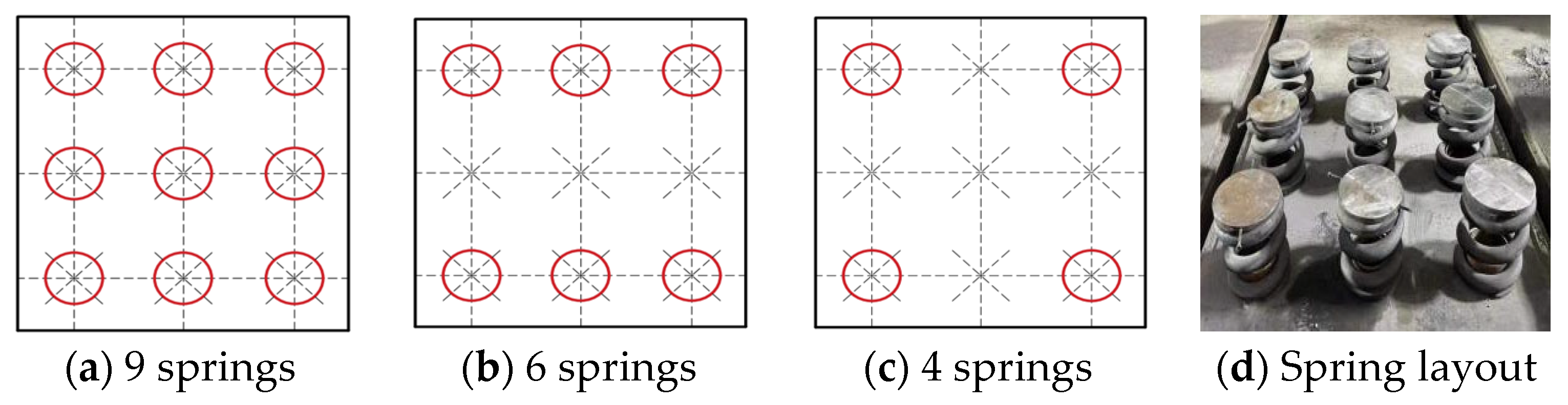
| Loading Conditions | Number of Springs/ Size | Equivalent Bed Coefficient /(×103 kN-m−3) | Equivalent Stratum (Geology) |
|---|---|---|---|
| Option I | 9 | 10.16 | loose sandy soil |
| Option I | 6 | 6.77 | soft clay |
| Option 3 | 4 | 4.52 | freshly filled soil |
Disclaimer/Publisher’s Note: The statements, opinions and data contained in all publications are solely those of the individual author(s) and contributor(s) and not of MDPI and/or the editor(s). MDPI and/or the editor(s) disclaim responsibility for any injury to people or property resulting from any ideas, methods, instructions or products referred to in the content. |
© 2023 by the authors. Licensee MDPI, Basel, Switzerland. This article is an open access article distributed under the terms and conditions of the Creative Commons Attribution (CC BY) license (https://creativecommons.org/licenses/by/4.0/).
Share and Cite
Xu, Y.; Huang, Z.; Zhang, C.; Pang, Y.; Liu, T. Bearing Capacities and Failure Behaviors of F-Type Socket Joint in Rectangular Pipe Jacking Tunnel. Appl. Sci. 2023, 13, 5442. https://doi.org/10.3390/app13095442
Xu Y, Huang Z, Zhang C, Pang Y, Liu T. Bearing Capacities and Failure Behaviors of F-Type Socket Joint in Rectangular Pipe Jacking Tunnel. Applied Sciences. 2023; 13(9):5442. https://doi.org/10.3390/app13095442
Chicago/Turabian StyleXu, Youjun, Zhengdong Huang, Chao Zhang, Yuekui Pang, and Tianyu Liu. 2023. "Bearing Capacities and Failure Behaviors of F-Type Socket Joint in Rectangular Pipe Jacking Tunnel" Applied Sciences 13, no. 9: 5442. https://doi.org/10.3390/app13095442
APA StyleXu, Y., Huang, Z., Zhang, C., Pang, Y., & Liu, T. (2023). Bearing Capacities and Failure Behaviors of F-Type Socket Joint in Rectangular Pipe Jacking Tunnel. Applied Sciences, 13(9), 5442. https://doi.org/10.3390/app13095442